

Page 1
damage done in transmit or a mistake in type. If any damage or mistake
damage done in transmit or a mistake in type. If any damage or mistakedamage done in transmit or a mistake in type. If any damage or mistake
damage done in transmit or a mistake in type. If any damage or mistake
If not observed, a trouble of injury or an accident will be caused,
If not observed, a trouble of injury or an accident will be caused,If not observed, a trouble of injury or an accident will be caused,
If not observed, a trouble of injury or an accident will be caused,
damage done in transmit or a mistake in type. If any damage or mistake
damage done in transmit or a mistake in type. If any damage or mistakedamage done in transmit or a mistake in type. If any damage or mistake
damage done in transmit or a mistake in type. If any damage or mistake
Standard
Standard Instruction
Standard Standard
(SOS TYPE PRESSURE TRANSMITTER)
(SOS TYPE PRESSURE TRANSMITTER)
(SOS TYPE PRESSURE TRANSMITTER)(SOS TYPE PRESSURE TRANSMITTER)
Prior to starting use of the product, read this instruction manual with full care. Be sure to
Prior to starting use of the product, read this instruction manual with full care. Be sure to
Prior to starting use of the product, read this instruction manual with full care. Be sure toPrior to starting use of the product, read this instruction manual with full care. Be sure to
observe the important points shown with a caution mark in this manual. File this instruction
observe the important points shown with a caution mark in this manual. File this instruction
observe the important points shown with a caution mark in this manual. File this instructionobserve the important points shown with a caution mark in this manual. File this instruction
manual nearby so that you may refer thereto whenever required.
manual nearby so that you may refer thereto whenever required.
manual nearby so that you may refer thereto whenever required.manual nearby so that you may refer thereto whenever required.
MARKS AND IMPORTANT POINTS USED IN THIS MANUAL.
MARKS AND IMPORTANT POINTS USED IN THIS MANUAL.
MARKS AND IMPORTANT POINTS USED IN THIS MANUAL.MARKS AND IMPORTANT POINTS USED IN THIS MANUAL.
What you must not do absolutely or you must pay full attention or refer thereto are explained
What you must not do absolutely or you must pay full attention or refer thereto are explained
What you must not do absolutely or you must pay full attention or refer thereto are explainedWhat you must not do absolutely or you must pay full attention or refer thereto are explained
with the following marks. Be sure to read the parts of text marked with such marks.
with the following marks. Be sure to read the parts of text marked with such marks.
with the following marks. Be sure to read the parts of text marked with such marks.with the following marks. Be sure to read the parts of text marked with such marks.
WARNING
WARNING
WARNING WARNING
resulting in endangering human body. What is explained with this
resulting in endangering human body. What is explained with this
resulting in endangering human body. What is explained with thisresulting in endangering human body. What is explained with this
mark shall not be done absolutely.
mark shall not be done absolutely.
mark shall not be done absolutely.mark shall not be done absolutely.
Application Models : NS100A
Application Models : NS100A
Application Models : NS100AApplication Models : NS100A
nstruction Manual
nstruction nstruction
anual
anualanual
KS60002-1H
Important points and limitations to be observed for operation
Important points and limitations to be observed for operation
Important points and limitations to be observed for operationImportant points and limitations to be observed for operation
and handling . Be sure to read for avoiding marking a mistake.
and handling . Be sure to read for avoiding marking a mistake.
and handling . Be sure to read for avoiding marking a mistake.and handling . Be sure to read for avoiding marking a mistake.
1.
1. Preface
Preface
1.1.
PrefacePreface
Thank you very much for your purchase of a MinebeaMitsumi type pressure
Thank you very much for your purchase of a MinebeaMitsumi type pressure
Thank you very much for your purchase of a MinebeaMitsumi type pressureThank you very much for your purchase of a MinebeaMitsumi type pressure
transmitter this time. To begin with, check whether or not there is any
transmitter this time. To begin with, check whether or not there is any
transmitter this time. To begin with, check whether or not there is anytransmitter this time. To begin with, check whether or not there is any
should be found, be sure to contact the dealer from which you purchased
should be found, be sure to contact the dealer from which you purchased
should be found, be sure to contact the dealer from which you purchasedshould be found, be sure to contact the dealer from which you purchased
this product or our sales office nearby.
this product or our sales office nearby.
this product or our sales office nearby.this product or our sales office nearby.
Outline
Outline
2.
2.
OutlineOutline
2.2.
NS100A series are pressure transmitters into which SOS (silicon on sapphire)
NS100A series are pressure transmitters into which SOS (silicon on sapphire)
NS100A series are pressure transmitters into which SOS (silicon on sapphire)NS100A series are pressure transmitters into which SOS (silicon on sapphire)
technology has been introduced. They have high reliability and durability.
technology has been introduced. They have high reliability and durability.
technology has been introduced. They have high reliability and durability.technology has been introduced. They have high reliability and durability.
Standard output are 4mA to 20mA, 0V to 5V, 0V to 10V.
Standard output are 4mA to 20mA, 0V to 5V, 0V to 10V.
Standard output are 4mA to 20mA, 0V to 5V, 0V to 10V.Standard output are 4mA to 20mA, 0V to 5V, 0V to 10V.
NOTE:
NOTE:
For special type products other than the standard unit, refer to the enclosed
For special type products other than the standard unit, refer to the enclosed
NOTE:NOTE:
For special type products other than the standard unit, refer to the enclosedFor special type products other than the standard unit, refer to the enclosed
supplementary notes and instruction manual or the specification figure of
supplementary notes and instruction manual or the specification figure of
supplementary notes and instruction manual or the specification figure ofsupplementary notes and instruction manual or the specification figure of
external appearance . (Power voltage, wiring diagram etc.)
external appearance . (Power voltage, wiring diagram etc.)
external appearance . (Power voltage, wiring diagram etc.)external appearance . (Power voltage, wiring diagram etc.)
WARING
WARING
WARING WARING
In the case of static pressure, use it within the range of rated pressure and in
In the case of static pressure, use it within the range of rated pressure and in
In the case of static pressure, use it within the range of rated pressure and inIn the case of static pressure, use it within the range of rated pressure and in
・・・・
the case of dynamic pressure, use it within 70% of the rated capacity.
the case of dynamic pressure, use it within 70% of the rated capacity.
the case of dynamic pressure, use it within 70% of the rated capacity.the case of dynamic pressure, use it within 70% of the rated capacity.
・・・・
A voltage exceeding the max, applying voltage shall not be applied to the input
A voltage exceeding the max, applying voltage shall not be applied to the input
A voltage exceeding the max, applying voltage shall not be applied to the inputA voltage exceeding the max, applying voltage shall not be applied to the input
terminal.
terminal.
terminal.terminal.
・・・・
Avoid using the product in atmosphere containing corrosive gas, chloric
Avoid using the product in atmosphere containing corrosive gas, chloric
Avoid using the product in atmosphere containing corrosive gas, chloricAvoid using the product in atmosphere containing corrosive gas, chloric
composition etc.
composition etc.
composition etc.composition etc.
・・・・
When fitting this product to medical treatment apparatuses and instruments
When fitting this product to medical treatment apparatuses and instruments
When fitting this product to medical treatment apparatuses and instrumentsWhen fitting this product to medical treatment apparatuses and instruments
involving human life, be sure to provide a protective circuit in preparation for
involving human life, be sure to provide a protective circuit in preparation for
involving human life, be sure to provide a protective circuit in preparation forinvolving human life, be sure to provide a protective circuit in preparation for
stop of function of the pressure transmitter.
stop of function of the pressure transmitter.
stop of function of the pressure transmitter.stop of function of the pressure transmitter.
MinebeaMitsumi Inc.
MinebeaMitsumi Inc.
Sensing Device Business Unit
Sensing Device Business Unit
1
1
Page 2
3.
A :
A : A :
A :
3.
Construction of P/N
Construction of P/N
3.3.
Construction of P/NConstruction of P/N
Name of Series
Name of Series Rated capacity
Name of SeriesName of Series
NS100A
NS100A ***
NS100ANS100A
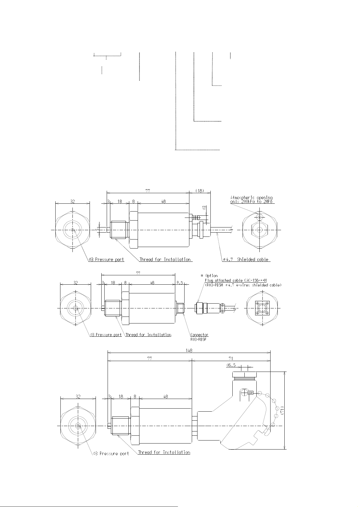
4.
4.
Outline dimension
Outline dimension
4.4.
Outline dimensionOutline dimension
Rated capacity
Rated capacityRated capacity
***
******
200 KPa~500KP:KP
200 KPa~500KP:KP
200 KPa~500KP:KP200 KPa~500KP:KP
1MP~50MP:MP
1MP~50MP:MP 3:Terminal box
1MP~50MP:MP1MP~50MP:MP
No display : gage pressure
No display : gage pressure Thread for installation
No display : gage pressureNo display : gage pressure
F : negative pressure
F : negative pressure
F : negative pressure F : negative pressure
Unit
Unit
UnitUnit
**** **** ---- **** **** **** ****
absolute pressure
absolute pressure
absolute pressureabsolute pressure
Interface
Interface
InterfaceInterface
1:Cable direct
1:Cable direct
1:Cable direct1:Cable direct
2:Connector
2:Connector
2:Connector2:Connector
3:Terminal box
3:Terminal box3:Terminal box
Thread for installation
Thread for installationThread for installation
(normal designation )
(normal designation )
(normal designation )(normal designation )
1:1/8 External thread
1:1/8 External thread
1:1/8 External thread1:1/8 External thread
2:1/4 External thread
2:1/4 External thread
2:1/4 External thread2:1/4 External thread
3:3/8 External thread
3:3/8 External thread
3:3/8 External thread3:3/8 External thread
Thread for installation
Thread for installation
Thread for installationThread for installation
(Configuration)
(Configuration)
(Configuration)(Configuration)
1:G
1:G
1:G1:G
2:R
2:R
2:R2:R
Output
Output
OutputOutput
1:4mA to 20mA
1:4mA to 20mA
1:4mA to 20mA1:4mA to 20mA
2:0V to 5V
2:0V to 5V
2:0V to 5V2:0V to 5V
3:0V to 10V
3:0V to 10V
3:0V to 10V3:0V to 10V
KS60002-1H
MinebeaMitsumi Inc.
MinebeaMitsumi Inc.
Sensing Device Business Unit
Sensing Device Business Unit
2
2
Page 3

5.
Compensated temperature range
Compensated temperature rangeCompensated temperature range
Compensated temperature range
Ambient humidity
Ambient humidityAmbient humidity
Ambient humidity
85% RH or less (shall be free from
85% RH or less (shall be free from85% RH or less (shall be free from
85% RH or less (shall be free from
If disused, dispose of it, taking into full consideration the environmental condition.
If disused, dispose of it, taking into full consideration the environmental condition.If disused, dispose of it, taking into full consideration the environmental condition.
If disused, dispose of it, taking into full consideration the environmental condition.
5. Specification
Specification
5.5.
SpecificationSpecification
Rated capacity
Rated capacity 200,500 kPa 1,2,5,10,20,25,30,35,50 MPa
Rated capacityRated capacity
Safe overload
Safe overload 200%R.C.
Safe overloadSafe overload
Accuracy
Accuracy 0.2%R.O.
AccuracyAccuracy
(Non-linearity,hysterresis and repeatability are included)
Output
Output
OutputOutput
Power supply voltage
Power supply voltage 24 VDC (18VDC to 28VDC)
Power supply voltagePower supply voltage
Insulation resistance
Insulation resistance 1000MΩ or more (Lead to Main body)
Insulation resistanceInsulation resistance
Consumption current
Consumption current About 20mA
Consumption currentConsumption current
Safe temperature range
Safe temperature range -30℃ to 80℃
Safe temperature rangeSafe temperature range
Temperature effect on zero point
Temperature effect on zero point
Temperature effect on zero pointTemperature effect on zero point
Temperature effect on output
Temperature effect on output ±0.2%LOAD/10℃
Temperature effect on outputTemperature effect on output
Pressure port
Pressure port Stainless steel
Pressure portPressure port
Pressure receiving section
Pressure receiving section Sapphire
Pressure receiving sectionPressure receiving section
Cable connection
Cable connection Cable direct、Connector type、Terminal box type
Cable connectionCable connection
Thread for installation
Thread for installation
Thread for installationThread for installation
Constructions
Constructions Indoor type
ConstructionsConstructions
Clamping torque
Clamping torque
Clamping torqueClamping torque
Weight
Weight Approx.200g (Main body only) however, terminal box type is
WeightWeight
200,500 kPa 1,2,5,10,20,25,30,35,50 MPa
200,500 kPa 1,2,5,10,20,25,30,35,50 MPa200,500 kPa 1,2,5,10,20,25,30,35,50 MPa
200%R.C.
200%R.C.200%R.C.
0.2%R.O.
0.2%R.O.0.2%R.O.
(Non-linearity,hysterresis and repeatability are included)
(Non-linearity,hysterresis and repeatability are included)(Non-linearity,hysterresis and repeatability are included)
4mA to 20mA (load resistance 500Ωor less)
4mA to 20mA (load resistance 500Ωor less)
4mA to 20mA (load resistance 500Ωor less)4mA to 20mA (load resistance 500Ωor less)
0V to 5V (Load resistance 5kΩ or more)
0V to 5V (Load resistance 5kΩ or more)
0V to 5V (Load resistance 5kΩ or more)0V to 5V (Load resistance 5kΩ or more)
0V to 10V (Load resistance 5kΩ or more)
0V to 10V (Load resistance 5kΩ or more)
0V to 10V (Load resistance 5kΩ or more)0V to 10V (Load resistance 5kΩ or more)
24 VDC (18VDC to 28VDC)
24 VDC (18VDC to 28VDC)24 VDC (18VDC to 28VDC)
1000MΩ or more (Lead to Main body)
1000MΩ or more (Lead to Main body)1000MΩ or more (Lead to Main body)
About 20mA
About 20mAAbout 20mA
-20℃ to 70℃
-20℃ to 70℃
-20℃ to 70℃-20℃ to 70℃
-30℃ to 80℃
-30℃ to 80℃-30℃ to 80℃
±0.2%R.O./10℃
±0.2%R.O./10℃
±0.2%R.O./10℃±0.2%R.O./10℃
±0.2%LOAD/10℃
±0.2%LOAD/10℃±0.2%LOAD/10℃
Stainless steel
Stainless steelStainless steel
Sapphire
SapphireSapphire
Cable direct、Connector type、Terminal box type
Cable direct、Connector type、Terminal box typeCable direct、Connector type、Terminal box type
G(PF)orR(PT) 1/8,1/4,3/8,
G(PF)orR(PT) 1/8,1/4,3/8,
G(PF)orR(PT) 1/8,1/4,3/8,G(PF)orR(PT) 1/8,1/4,3/8,
Indoor type
Indoor type Indoor type
20 to 40 N・m
20 to 40 N・m
20 to 40 N・m 20 to 40 N・m
Approx.200g (Main body only) however, terminal box type is
Approx.200g (Main body only) however, terminal box type isApprox.200g (Main body only) however, terminal box type is
approx. 400g.
approx. 400g.
approx. 400g.approx. 400g.
KS60002-1H
6.
6.
Important points for use
Important points for use
6.6.
Important points for useImportant points for use
①①①①
Fit it within the range of tightening torques of 20 - 40 N・m.
Fit it within the range of tightening torques of 20 - 40 N・m.
Fit it within the range of tightening torques of 20 - 40 N・m.Fit it within the range of tightening torques of 20 - 40 N・m.
②②②②
If there should be any impact pressure or vibration, set it in such a way that the
If there should be any impact pressure or vibration, set it in such a way that the
If there should be any impact pressure or vibration, set it in such a way that theIf there should be any impact pressure or vibration, set it in such a way that the
value taking into consideration surging pressure does not exceed the rated
value taking into consideration surging pressure does not exceed the rated
value taking into consideration surging pressure does not exceed the ratedvalue taking into consideration surging pressure does not exceed the rated
pressure of pressure transmitter.
pressure of pressure transmitter.
pressure of pressure transmitter.pressure of pressure transmitter.
Use it at an ambient temperature in the temperature compensation range.
Use it at an ambient temperature in the temperature compensation range.
Use it at an ambient temperature in the temperature compensation range.Use it at an ambient temperature in the temperature compensation range.
③③③③
Avoid rapid change in temperature and direct heat.
Avoid rapid change in temperature and direct heat.
④④④④
Avoid rapid change in temperature and direct heat.Avoid rapid change in temperature and direct heat.
⑤⑤⑤⑤
though the instrument has the features of drip-proofed constructions, avoid
though the instrument has the features of drip-proofed constructions, avoid
though the instrument has the features of drip-proofed constructions, avoidthough the instrument has the features of drip-proofed constructions, avoid
using it where water may splash or in the water
using it where water may splash or in the water
using it where water may splash or in the waterusing it where water may splash or in the water
⑥⑥⑥⑥
Shall be installed in such a place where vibration and impact are as little as
Shall be installed in such a place where vibration and impact are as little as
Shall be installed in such a place where vibration and impact are as little asShall be installed in such a place where vibration and impact are as little as
possible.
possible.
possible.possible.
⑦⑦⑦⑦
In vibration environment, the cord shall be fixed in the vicinity of cable outlet
In vibration environment, the cord shall be fixed in the vicinity of cable outlet
In vibration environment, the cord shall be fixed in the vicinity of cable outletIn vibration environment, the cord shall be fixed in the vicinity of cable outlet
and vibration stop, be provided.
and vibration stop, be provided.
and vibration stop, be provided.and vibration stop, be provided.
⑧⑧⑧⑧
In an environment where screws tend to loosen, retighten periodically or provide
In an environment where screws tend to loosen, retighten periodically or provide
In an environment where screws tend to loosen, retighten periodically or provideIn an environment where screws tend to loosen, retighten periodically or provide
detent as required.
detent as required.
detent as required.detent as required.
⑨⑨⑨⑨
Do not install it near an apparatus or machine generating strong magnetism or
Do not install it near an apparatus or machine generating strong magnetism or
Do not install it near an apparatus or machine generating strong magnetism orDo not install it near an apparatus or machine generating strong magnetism or
strong electromagnetic waves.
strong electromagnetic waves.
strong electromagnetic waves.strong electromagnetic waves.
⑩⑩⑩⑩
Under special operating environment and in the case of special pressure medium,
Under special operating environment and in the case of special pressure medium,
Under special operating environment and in the case of special pressure medium,Under special operating environment and in the case of special pressure medium,
consult with us once before use.
consult with us once before use.
consult with us once before use.consult with us once before use.
Do not disassemble the pressure transmitter.
Do not disassemble the pressure transmitter.
⑪⑪⑪⑪
Do not disassemble the pressure transmitter.Do not disassemble the pressure transmitter.
Do not drop the pressure transmitter or give a shock thereto.
Do not drop the pressure transmitter or give a shock thereto.
⑫⑫⑫⑫
Do not drop the pressure transmitter or give a shock thereto.Do not drop the pressure transmitter or give a shock thereto.
⑬⑬⑬⑬
Ambient temperature
Ambient temperature
Ambient temperatureAmbient temperature
-20
-20 ℃℃℃℃ ---- 70
-20-20
formation of dew).
formation of dew).
formation of dew).formation of dew).
70 ℃℃℃℃
7070
Connecting diagram
Connecting diagram
7.
7.
Connecting diagramConnecting diagram
7.7.
Voltage output type
Voltage output type Current output type
Voltage output typeVoltage output type
Red
Red Red
Supply voltage input (+24V)
Supply voltage input (+24V) Supply voltage input (+24V)
RedRed
Supply voltage input (+24V)Supply voltage input (+24V)
White
White
Supply voltage input (COM)
Supply voltage input (COM)
WhiteWhite
Supply voltage input (COM)Supply voltage input (COM)
Green
Green Green
Voltage output (+)
Voltage output (+) Current output (+)
GreenGreen
Voltage output (+)Voltage output (+)
Blue
Blue
Voltage output (COM)
Voltage output (COM)
BlueBlue
Voltage output (COM)Voltage output (COM)
Yellow
Yellow Yellow
Shield (Earthed)
Shield (Earthed)
YellowYellow
Shield (Earthed)Shield (Earthed)
MinebeaMitsumi Inc.
MinebeaMitsumi Inc.
Sensing Device Business Unit
Sensing Device Business Unit
Red
RedRed
Green
GreenGreen
Yellow
YellowYellow
Current output type
Current output type Current output type
Supply voltage input (+24V)
Supply voltage input (+24V)Supply voltage input (+24V)
Current output (+)
Current output (+)Current output (+)
Shield (Earthed)
Shield (Earthed)
Shield (Earthed)Shield (Earthed)
3
3
Page 4

8.
8.
Wiring diagram
Wiring diagram
8.8.
Wiring diagramWiring diagram
Voltage output type
Voltage output type
Voltage output typeVoltage output type
Cable method
Connector method
Terminal Box method
Current output type
Current output type
Current output typeCurrent output type
Cable method
KS60002-1H
Connector method
Terminal Box method
①①①①
Wiring of 4 line type serves as the standard for the purpose of compensation of the
Wiring of 4 line type serves as the standard for the purpose of compensation of the
Wiring of 4 line type serves as the standard for the purpose of compensation of theWiring of 4 line type serves as the standard for the purpose of compensation of the
zero point error according voltage output use of this unit to cable length. Although
zero point error according voltage output use of this unit to cable length. Although
zero point error according voltage output use of this unit to cable length. Althoughzero point error according voltage output use of this unit to cable length. Although
the use as a wiring of 3 line type (it is common COM about white or blue ) is also
the use as a wiring of 3 line type (it is common COM about white or blue ) is also
the use as a wiring of 3 line type (it is common COM about white or blue ) is alsothe use as a wiring of 3 line type (it is common COM about white or blue ) is also
possible, when cable length is extended, the zero point error of about 1.3 mV/m
possible, when cable length is extended, the zero point error of about 1.3 mV/m
possible, when cable length is extended, the zero point error of about 1.3 mV/mpossible, when cable length is extended, the zero point error of about 1.3 mV/m
occurs. (at the time of our company cable use)
occurs. (at the time of our company cable use)
occurs. (at the time of our company cable use)occurs. (at the time of our company cable use)
②②②②
The shield wire must be earthed without fail. If not earthed, when a surging voltage
The shield wire must be earthed without fail. If not earthed, when a surging voltage
The shield wire must be earthed without fail. If not earthed, when a surging voltageThe shield wire must be earthed without fail. If not earthed, when a surging voltage
is applied, pressure transmitter will result in damage.
is applied, pressure transmitter will result in damage.
is applied, pressure transmitter will result in damage.is applied, pressure transmitter will result in damage.
③③③③
Separate the cable as much as possible from the power line. If not separated as
Separate the cable as much as possible from the power line. If not separated as
Separate the cable as much as possible from the power line. If not separated asSeparate the cable as much as possible from the power line. If not separated as
much as possible, a trouble of output interference will be caused due to power
much as possible, a trouble of output interference will be caused due to power
much as possible, a trouble of output interference will be caused due to powermuch as possible, a trouble of output interference will be caused due to power
noise etc.
noise etc.
noise etc.noise etc.
④④④④
When measuring voltage output, load resistance will be more than 5Ω.
When measuring voltage output, load resistance will be more than 5Ω.
When measuring voltage output, load resistance will be more than 5Ω.When measuring voltage output, load resistance will be more than 5Ω.
When measuring current output, load resistance will be less then 500Ω.
When measuring current output, load resistance will be less then 500Ω.
When measuring current output, load resistance will be less then 500Ω.When measuring current output, load resistance will be less then 500Ω.
'9.
'9.
'9.'9.
Countermeasures to be taken for abnormalities.
Countermeasures to be taken for abnormalities.
Countermeasures to be taken for abnormalities.Countermeasures to be taken for abnormalities.
If there should arise an abnormality in the pressure transmitter, contact our company
If there should arise an abnormality in the pressure transmitter, contact our company
If there should arise an abnormality in the pressure transmitter, contact our companyIf there should arise an abnormality in the pressure transmitter, contact our company
or dealer from which you have purchased.
or dealer from which you have purchased.
or dealer from which you have purchased.or dealer from which you have purchased.
The content of this manual is subject to change with out notice.
The content of this manual is subject to change with out notice.
The content of this manual is subject to change with out notice.The content of this manual is subject to change with out notice.
MinebeaMitsumi Inc.
MinebeaMitsumi Inc.
Sensing Device Business Unit
Sensing Device Business Unit
4
4
 Loading...