

Page 1

GRAPHIC DIGITAL INDICATOR
CC-Link Interface
CSD-912-73
Instruction Manual
MINEBEA Co., Ltd.
Measuring Components Business Unit
EN294-1424
III
Page 2

FOREWORD
Thank you very much for your purchasing Minebea’s Graphic Digital Indicator, model
CSD-912-73.
This manual explains the handling procedures and the notes when it would be used. Make
use of it properly after reading through the manual carefully.
Be sure to deliver the manual to the end user. Moreover, the end user should keep the
manual at hand after reading it over.
This manual is intended for the technical experts to read. When you read this instruction
manual, the program basic knowledge of Mitsubishi general-purpose sequencer and the
CC-Link interface are needed.
Marks and arrangements used in this manual
The following marks are attached to the explanation on the matters that indicate “Don’t do
this.”, “Take care” and “For reference”.
Be sure to read these items where these marks are attached.
Warning
Warning may cause injury or accident that may harm to the operator.
Don’t do these things described here.
Caution
It is a description when the occurrence only of assumption of danger by which the user owes injury when handling is
mistaken, and material damage is assumed.
Caution during operation and working.
Be sure to read the item to prevent malfunction.
I
Page 3

About the view of this book
This instruction manual explains the connection method and use of the CC-Link interface
specification of the option for CSD-912 are explained. Please see the CSD-912 instruction
manual about other main body functions and a basic method of handling and notes.
CSD-912 instruction manual (DRW No. EN294-1404*)
Moreover, please refer to the instruction manual of sequencer and its CC-Link interface for
the sequencer program and CC-Link.
●CC-Link is an abbreviation of “Control & Communication Link”
II
Page 4

Divisional history
Date Instruction manual No. Details of revised point
2011/02 DRW. NO.EN294-1424 First Version
III
Page 5

Index
FOREWORD
Marks and arrangements used in this manual
About the view of this book
Divisional history
Index
1.
2.
3.
................................................................................................................................................................................... IV
General
1-1. Features ................................................................................................................................... 1
Name and function of each point
2-1. Rear panel for CC-Link I/F ....................................................................................................... 2
Connecting method
3-1. Connector pin configuration for communication .................................................................. 3
3-2. Notes of Connection................................................................................................................ 3
...................................................................................................................................................................... I
............................................................................................ I
................................................................................................................................... II
......................................................................................................................................................... III
....................................................................................................................................................................... 1
............................................................................................................... 2
............................................................................................................................................ 3
4.
Setting of CC-Link connecting
4-1. Changeover of CC-Link communication setting change screen .......................................... 4
4-2. Items of CC-Link setting ......................................................................................................... 4
5.
PLC memory explanation
5-1. Address .................................................................................................................................... 6
5-2. Address map ............................................................................................................................ 7
6.
Operation method
6-1. Writing the set value (Special data area) .............................................................................. 26
6-2. Writing/Reading by general command ................................................................................. 26
6-3. Shift to status where it is possible to communicate ........................................................... 28
6-4. Error condition/Reset requesting flag .................................................................................. 28
6-5. CPU normal operation signal ................................................................................................ 29
6-6. Calibration procedure by CC-Link communication .......................................................... 30
7.
Specifications of interface
.............................................................................................................................................. 26
..................................................................................................................... 4
................................................................................................................................ 6
............................................................................................................................ 31
7-1. Specifications of CC-Link interface ...................................................................................... 31
7-2. Accessories ........................................................................................................................... 31
IV
Page 6

1.General
This unit is a remote device station of CC-Link Ver.1.10.
This unit can be connected with the mastering station of CC-Link Ver.1.10.
1-1.Features
Main features for CSD-912-73 are as follows:
(1) This unit can be controlled by using remote I/O and register of the sequencer, so the program volume
of the sequencer can be reduced.
(2) The wiring with the sequencer can be reduced.
1
Page 7
r
2.Name and function of each point
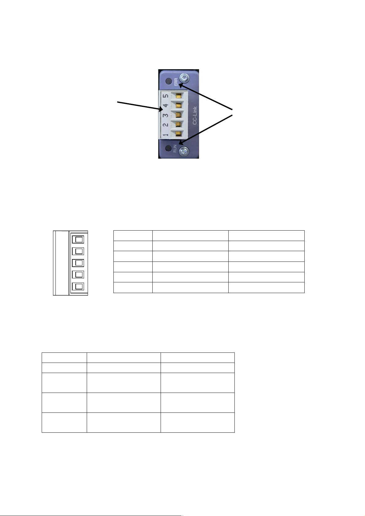
2-1.Rear panel for CC-Link I/F
(1) Communication connecto
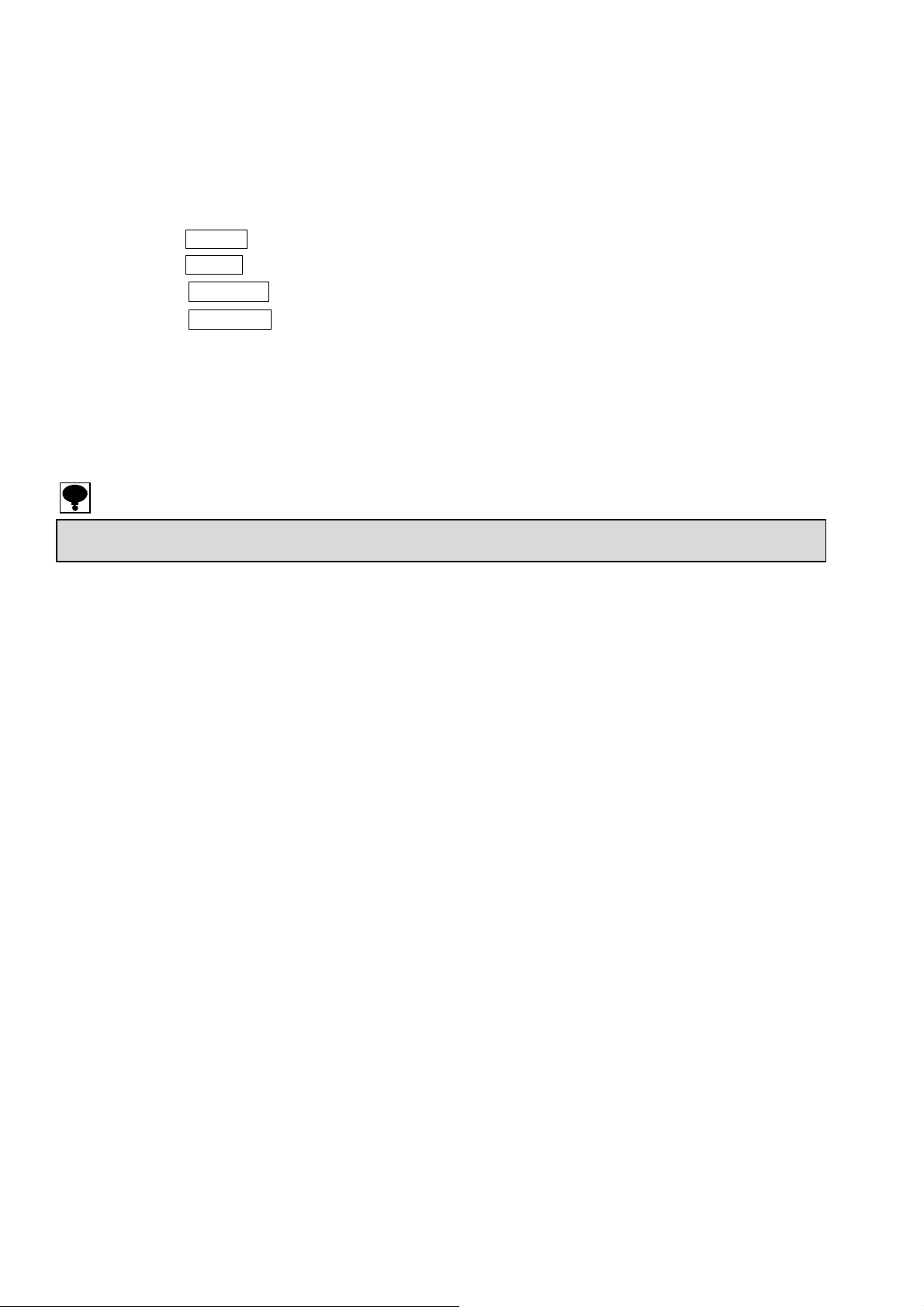
(1) Communication connector
Connector type terminal block for CC-Link interface.
Connector pin configuration for communication is as follows
※ Suitable plug : MSTB 2,5-ST-5,08 ABGY AU by PHOENIX CONTACT. ※to be attached.
※ “SLD” and “FG" are connected inside.
※ The internal circuit and photo coupler are insulated.
(2) Status LED
The communication status is expressed with two LED.
1 2 3 4 5
Status RUN ERR
Light off - Normal
Green LED
Light on
Red LED
Light on
Red LED
Light on/off
FG
SLD
DG
DB
DA
Hardware error Hardware error
Pin No. Signal name Contents
1 DA Signal line DA side
2 DB Signal line DB side
3 DG Signal line ground
4 SLD Shield
5 FG Frame ground
Normal -
- CRC error
(2) Status LED
2
Page 8

3.Connecting method
3-1.Connector pin configuration for communication
Refer to 2-1. Rear panel for CC-Link I/F (1), Connector for communication.
3-2.Notes of Connection
z When the wiring, be sure to the instrument power supply is OFF.
z Do not supply the AC power until complete the installation. This instrument does not have power
switch (ON/OFF).
z Do not fell or make a strong impact on this instrument rear panel terminal block because it is made
of resin.
z Striped electrical cable tip length is 6 mm.
z The tightening torque of terminal screws on the terminal block is 0.5~0.6 N・m.
z Cables which connecting this instrument isolate from noise sources, for example, power supply line
and I/O for control's as much as possible.
z Be sure to connect the ground wire must be D single ground. Do not common the ground with a
kind of power supply.
z For CC-Link cable connection, use twist pear cable wire with shield (Cable for CC-link) and connect
the shield in terminal block's SLD terminal or F.G.terminal.
• Connect the termination to the CC-Link connector to electrical termination which is far from PLC as possible.
• Use the connecting cable for CC-Li nk.
• Refer to the “Construction and specification of network system” from the latest version of CC-Link Cable Wiring Manual
published by CC-Link Partner Association about communication speed and cable length
3
Page 9
4.Setting of CC-Link connecting
Please set the following when you use CC-LINK interface.
4-1.Changeover of CC-Link communication setting change screen
Change from the standard measurement mode to the function mode by the following operations.
1) Touch the MENU key.
2) Touch the NEXT key.
3) Touch the OPTION key.
4) Touch the CC-LINK setting key.
4-2.Items of CC-Link setting
(1) The number of occupied stations.
Number of occupied stations is set.
Selectable from [1 station], [2stations], [4 stations].
Default has set as [4 stations].
• Setting changes for occupi ed stations No. is corresponding to this software after ROM Ver.1.300.Before ROM Ver.1.200 is 4
station occupied station No.
(2) Setting of the stations
Execute the setting of the station No.
When 1 station is occupied : selectable from station No.01 to 64.
When 2 stations are occupied : selectable from station No.01 to 63
When 4 stations are occupied : selectable from station No.01 to 61.
The occupied station of this instrument is 1., 2, 4 stations.
※When 2 stations are occupied,and station No. is set as “01”,01 to 02 stations are occupied.
※When 4 stations are occupied,and station No. is set as “01”,01 to 04 stations are occupied.
Therefore, the station number must not overlap.
Default has selected [01].
(3) Setting of baud rate
Communication speed (unit: bps) is set.
Selectable from [156k], [625k], [2.5M], [5M] or [10M].
Default has set as [156k].
4
Page 10
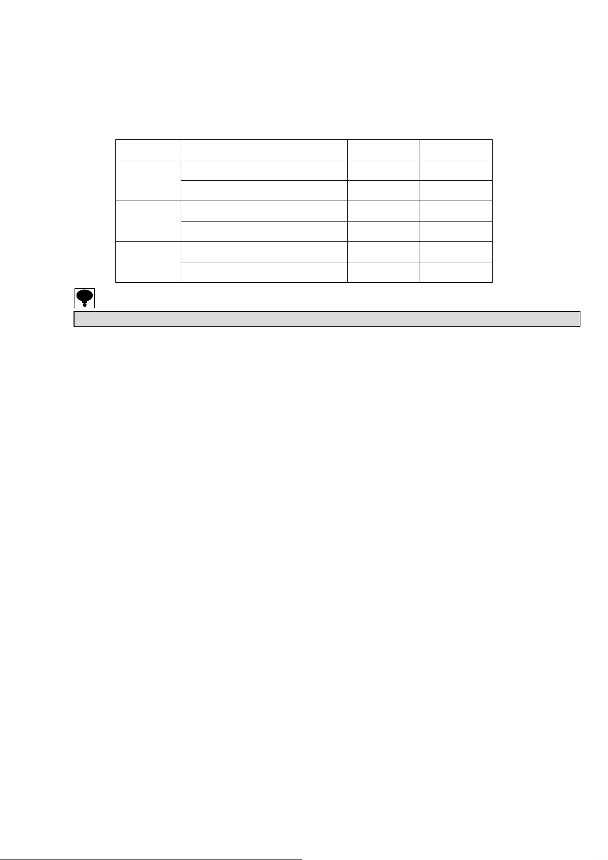
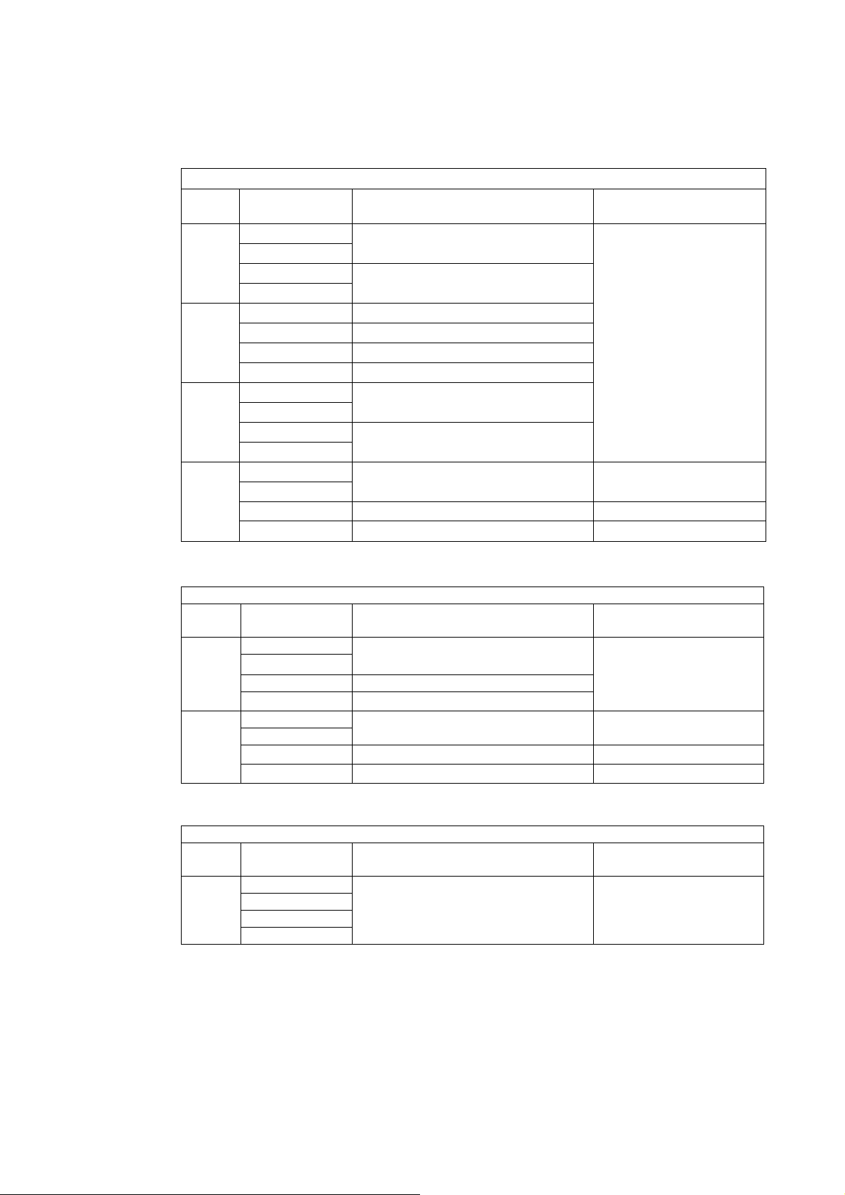
(4) Data display method of 32 bit
32 bits data indication method is set.
Selectable from [Expression of standard binary] or [Sign in MSB].
Default has set as [Expression of standard binary].
Load value 32 bits data expression method Upper 16 bit Lower 16 bit
-1
Expression of standard binary
Sign in MSB
Expression of standard binary
-10
Sign in MSB
Expression of standard binary
-99999
Sign in MSB
• Setting value becomes effective at restarting the power supply. Please restart the power supply after the changes.
FFFFH FFFFH
8000H 0001H
FFFFH FFF6H
8000H 000AH
FFFEH 7961H
8001H 869FH
5
Page 11
5.PLC memory explanation
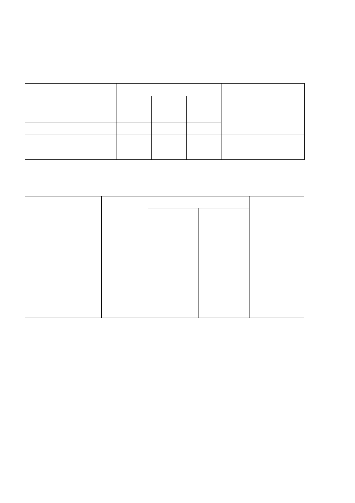
5-1.Address
A remote I/O(RX/RY:Bit handling register) and a remote register(RWw/RWr:Word handling register)
secures the zone in the master station depends on the occupied station number. As shown in the table
below in case of this unit.
Occupied station number
Type
Remote input 128points 64points 32points
Remote output 128points 64points 32points
4 stations
occupied
2 stations
occupied
1 station
occupied
I/O for each 16 points is
occupied as a system area.
Remarks
Remote
register
The address number of the remote station allocated to the mastering station is as shown in the table
below.
Station
No.
0 - - - - - - - - - - - - - - - - - - - -
1 RX0000 RY0000 RWw0000 RWr0000
2 RX0020 RY0020 RWw0004 RWr0004
3 RX0040 RY0040 RWw0008 RWr0008
~ ~ ~ ~ ~
10 RX0120 RY0120 RWw0024 RWr0024
~ ~ ~ ~ ~
64 RX07E0 RY07E0 RWw00FC RWr00FC
Master→Remote
Remote→Master
Remote input Remote output
16points 8points 4points
16points 8points 4points
Remote register
Remarks
Master→Remote Remote→Master
Specify the
master station
6
Page 12
5-2.Address map
5-2-1.Data detail
1) Batch/Discharge mode Remote register
Station
n : Value decided by setting of station No.
Station
n : Value decided by setting of station No.
Station
n : Value decided by setting of station No.
1
2
3
4
1
2
1
4 stations occupied (Master→Instrument)
Remote
register
RWwn
RWwn+1
RWwn+2
RWwn+3
RWwn+4
RWwn+5
RWwn+6
RWwn+7
RWwn+8
RWwn+9
RWwn+A
RWwn+B
RWwn+C
RWwn+D
RWwn+E
RWwn+F
Remote
register
RWwn
RWwn+1
RWwn+2 Undefined (16 bit)
RWwn+3
RWwn+4
RWwn+5
RWwn+6
RWwn+7
Remote
register
RWwn
RWwn+1
RWwn+2
RWwn+3
①Final (24 bit)
①Brand number (8bit)
①Preliminary 2 (32 bit)
①Preliminary 1 (16 bit)
①Free Fall (16 bit)
①Over (16 bit)
①Under (16 bit)
①Full (32 bit)
①Near zero (32 bit)
②General data area
③Command No. (Return)
④Operating mode (Return)
2 stations occupied (Master→Instrument)
①Final (24 bit)
①Brand number (8bit)
①Free Fall (16 bit)
②General data area
③Command No. (Return)
④Operating mode (Return)
1 station occupied (Master→Instrument)
Undefined
Contents Remarks
Contents Remarks
Contents Remarks
Special data area
Special data area
7
Page 13

① Special data area (4 stations, 2 stations)
When the set value is registered by using the set value writing request (request 1), the set value is
set in each area.
Details of each set value are shown as follows;
Data type Setting range
Final
Brand number (8bit) 8 bit binary with sign
Preliminary 2
Preliminary 1
Free Fall
Over 16 bit binary with sign
Under 16 bit binary with sign
Full 32 bit binary with sign
Near zero
32 bit binary with sign
32 bit binary with sign
16 bit binary with sign
16 bit binary with sign
32 bit binary with sign
0 ~ 999999
0 ~ 99
0 ~ 999999
0 ~ 32767
-32768 ~ 32767
0 ~ 32767
0 ~ 32767
0 ~ 999999
0 ~ 999999
② General data area (4 stations, 2 stations)
When the command order is executed by using the general command request (request 2), the set
value or the operating order code is set in this area.
Data type : 32 bit binary with sign
Setting range : Depends on the set value.
③ Command No. (4 stations, 2 stations)
When the command order is executed by using the general command request (request 2), the
command No. is set in this area.
The content of the general data area is set depending on the command set in this area.
Data type : 8 bit binary
Setting range : 0 ~ 255
④ Operation mode (4 stations, 2 stations)
When the operation mode is changed by using the operation mode changeover request (request 3),
the mode number is set in this area.
This function is prepared for future expansion.
Data type : 8 bit binary
Setting range : 0 ~ 255
2) Command list
The command No. and the value which is set in General data area when the command order is
executed by using the general command request (request 2) are shown in the next page.
8
Page 14

Writing set value and command order (Writing/reading selection = Writing [OFF])
Setting value or command order
Brand name 1 (The first ~4
th
Brand name 2(The 5
Brand name 3(The 9
~8
th
~12
th
Brand name 4(The 13th ~15
Hopper number
Final /S1
th
character)
character)
th
character)
th
character)
Command No.
(RWwnE)
1
2
3
4
5
6
Free fall /S4 7
Preliminary 1 /S3
Preliminary 2 /S2
8
9
Over 10
Under 11
Near zero
12
Full 13
Preset Tare 14
Supplementary time
Waiting time for judge after supplementary flow
Automatic free fall compensation
Initial full flow
Initial medium flow
Target of S1 operation
Target of S2 operation
Target of S3 operation
Target of S4 operation
Undefined
S1 operation
S2 operation
S3 operation
S4 operation
15
16
17
18
19
60
61
62
63
64
65
66
67
68
General data area
(RWwnC~RWwnD)
Katakana, alphabet, and numeric
values of 15 characters
0~99
0~999999/-999999~999999
0~999999/-999999~999999
0~999999/-999999~999999
0~999999/-999999~999999
0~999999
0~999999
0~999999
0~999999
0~999999
0~9999
0~9999
0~999999
0~999999
0~999999
1:GROSS , 2:NET
1:GROSS , 2:NET
1:GROSS , 2:NET
1:GROSS , 2:NET
1:MORE THAN, 2: LESS THAN
1:MORE THAN, 2: LESS THAN
1:MORE THAN, 2: LESS THAN
1:MORE THAN, 2: LESS THAN
Zero 0 1
Zero clear 0 2
Tare 0 3
Tare clear 0 4
Batch start
Discharge start
Accumulation command
Clear the last accumulated data
0 5
0 7
0 10
0 11
Pause 0 12
Restart 0 13
Clear the accumulated data of Brand
Clear the accumulated data of all Brand
0 14
0 15
Error reset 0 21
Print command
0 22
Net display 0 23
Gross display 0 24
The minimum Division 1000 1:[1],2:[2],3:[5],4:[10],5:[20],6:[50]
Weighing capacity 1001
1~999999
Zero adjustment 1002 Impossible to input.
Span adjustment 1003
1~999999
9
Page 15

Reading set value (Writing/reading selection = Reading [OFF])
1
Setting value or command order
Brand name 1 (The first ~4
Brand name 2(The 5
Brand name 3(The 9
Brand name 4(The 13
th
~8
th
~12
th
~15
Hopper number
Final /S1
th
character)
th
character)
th
character)
th
character)
Command No.
(RWwnE)
1
2
3
4
5
6
Free fall /S4 7
Preliminary 1 /S3
Preliminary 2 /S2
8
9
Over 10
Under 11
Near zero
12
Full 13
Preset Tare 14
Supplementary time
Waiting time for judge after supplementary flow
Automatic free fall compensation
Initial full flow
Initial medium flow
Brand accumulation total
Brand accumulation count
Brand number
15
16
17
18
19
20
21
32
General data area
(RWrnC~RWrnD)
Katakana, alphabet, and numeric
values of 15 characters
0~99
0~999999/-999999~999999
0~999999/-999999~999999
0~999999/-999999~999999
0~999999/-999999~999999
0~999999
0~999999
0~999999
0~999999
0~999999
0~9999
0~9999
0~999999
0~999999
0~999999
-99999999~99999999
0~999999
0~99
Undefined 57
Target of S1 operation
Target of S2 operation
Target of S3 operation
Target of S4 operation
Undefined
S1 operation
S2 operation
S3 operation
S4 operation
60
61
62
63
64
65
66
67
68
1:GROSS , 2:NET
1:GROSS , 2:NET
1:GROSS , 2:NET
1:GROSS , 2:NET
1:MORE THAN, 2: LESS THAN
1:MORE THAN, 2: LESS THAN
1:MORE THAN, 2: LESS THAN
1:MORE THAN, 2: LESS THAN
Undefined 69
The minimum Division 1000 1:[1],2:[2],3:[5],4:[10],5:[20],6:[50]
Weighing capacity 1001
1~999999
Zero adjustment 1002 Impossible to input.
Span adjustment 1003
10
:0= During measurement,
1~999999
1= During Zero adjustment,
Adjustment condition reading 1004
2= During Span adjustment
0
10
:0= None,
1= Occurrence of error
• Zero point mV/V registration and Span point mV/V registration can not be done.
10
Page 16

3) Remote register (Instrument→Master)
4 stations occupied
Station
1
2
3
4
n : Value decided by setting of station No.
Remote
register
RWrn
RWrn+1
RWrn+2
RWrn+3
RWrn+4
RWrn+5
RWrn+6
RWrn+7
RWrn+8
RWrn+9
RWrn+A
RWrn+B
RWrn+C
RWrn+D
RWrn+E
RWrn+F
①Net value
②Gross value
Accumulation value
③
④Error code
⑤Error assistance code
⑥Brand number (8bit)
Undefined
⑦General data area
⑧Command No.(Response)
⑨Operation mode(Response)
Contents Remarks
2 stations occupied
Station
1
2
n : Value decided by setting of station No.
Remote
register
RWrn
RWrn+1
RWrn+2
RWrn+3
RWrn+4
RWrn+5
RWrn+6
RWrn+7
⑩Indicate value
(Net value/Gross value)
④Error code
⑤Error assistance code
⑦General data area
⑧Command No.(Response)
⑨Operation mode(Response)
Contents Remarks
1 station occupied
Station
1
n : Value decided by setting of station No.
Remote
register
RWrn
RWrn+1
RWrn+2
RWrn+3
⑩Indicate value
(Net value/Gross value)
④Error code
⑤Error assistance code
Contents Remarks
11
Page 17

① Net value (4 stations)
Area for displaying the net value
Data type : 32 bit binary with sign
Setting range : -999999 ~ 999999
② Gross value (4 stations)
Area for displaying the gross value
Data type : 32 bit binary with sign
Setting range : -999999 ~ 999999
③ Accumulation value (4 stations)
Area for displaying the accumulation value
Data type : 32 bit binary with sign
Setting range : -99999999 ~ 99999999
④ Error code (4 stations, 2 stations, 1 station)
Area for displaying the error generating in the main body of the indicator
Refer to below table of ⑤ Error assistance code too.
Data type : 16 bits binary
Setting range : 0~255
12
Page 18

⑤ Error assistance code (4 stations, 2 stations, 1 station)
Error code
sequence error)
(Operation error)
(Other error)
Calibration
(
(Setting error)
Area for displaying the error No. generating in the main body of the indicator
Data type : 16 bits binary
Setting range : 0~255
Error
assistance
code
0 0 No error
SQERR 0 :
1
When measurement is stopped compulsorily by inputting the
temporary stop while weighing.
SQEER 1 :
When the condition of SAFETY CHECK is not satisfied.
SQEER 2 :
When the load value is under even if the supplementary flow is
executed.
SQEER 3 :
When there is contradiction in the amount of the comparison
value.
SQEER 4 :
When the batching time exceeds the limited time.
SQERR 5 :
When the discharging time exceeds the limited time.
SQERR 6 :
When the gross value < Final in discharge control.
SQERR 7 :
When the net value > (Final – free fall) in the start
SQERR 8 :
In controlling the nozzle, when the change of the load value
1
(Weighing
2
3
4
5
6
7
8
9
Contents
exceeds the zero band.
SQERR 9 :
The measurement begins in the condition that [START ABOVE
ZERO BAND] is [VALID], however the container is not put on the
measuring section.
Zero set error
In case of execute ZERO out of range of zero
A/Z error
In case of execute TARE out of range of tare.
EEPROM writing error.
EEPROM reading error.
When the setting is Span adjustment value > Weighing capacity.
Receiving undefined command
When undefined data is set at command No.
2
3
4
error
99
10
1
2
3 A/D conversion error.
31
32
0 TE-L error
1 TE-H error
2 SP-L error
)
3 SP-H error
4
0
1 Setting range error
2 Read-only state
• Refer to Error display in main body instruction manual about the contents of Error code.
13
Page 19

⑥ Brand number (4 stations)
It is area which showing the Brand number.
Data type : 8 bit binary
⑦ General data area (4 stations, 2 stations)
When the set value reading out command is ordered by using the general command request
(Request 2), this area represents the set value.
Data type : 32 bit binary with sign
⑧ Command No. (Response) (4 stations, 2 stations)
When the command order is executed by the general command request (Request 2), this area
represents that command No.
Data type : 8 bit binary
⑨ Operation mode (Response) (4 stations, 2 stations)
When the operation mode is changed by the operation mode changeover request (request 3), this
area represents that command No.
This function is prepared for future expansion.
Data type : 8 bit binary
⑩ Indicate value (Net value/Gross value) (2 stations, 1 station)
It is area which showing the Net value or Gross value by specified bit.
Data type : 32 bit binary with sign
Setting range : -999999 ~ 999999
14
Page 20

5-2-2.Relay zone
1) Remote input (Master→Instrument)
4 stations occupied
Device No. Contents Classification
RYn0
RYn1
RYn2 ②General command request (Request 2)
RYn3 ③Selection of writing/Reading out. (R/W)
RYn4
RYn5
RYn6
RYn7
RYn8
RYn9
RYnA
RYnB
RYnC
RYnD
RYnE
RYnF
RY(n+1)0 ⑤Zero
RY(n+1)1 ⑥Zero clear
RY(n+1)2
RY(n+1)3 ⑧Tare clear
RY(n+1)4 ⑨Hold
RY(n+1)5
RY(n+1)6 ⑪Gross display
RY(n+1)7
RY(n+1)8 ⑫Accumulation signal
RY(n+1)9
RY(n+1)A ⑭Error cancellation request flag
RY(n+1)B
RY(n+1)C
RY(n+1)D
RY(n+1)E
RY(n+1)F
RY(n+2)0
RY(n+2)1 2
RY(n+2)2 4
RY(n+2)3 8
RY(n+2)4
RY(n+2)5 20
RY(n+6)6 40
RY(n+6)7 80
~
RY(n+7)0
RY(n+7)1
RY(n+7)2
RY(n+7)3
RY(n+7)4
RY(n+7)5
RY(n+7)6
RY(n+7)7
RY(n+7)8
RY(n+7)9 ⑯Initialed data setting request flag
RY(n+7)A ⑰Error reset requesting flag
RY(n+7)B
RY(n+7)C
RY(n+7)D
RY(n+7)E
RY(n+7)F
①Setting value writing request (Request 1)
④Operation mode changeover request (Request 3)
⑦Tare
⑩Net display
⑬Accumulation clear
1
0
10
⑮Brand number
10
System reservation zone
10
1
n : Value decided by setting of station No.
Communication
Control signal
15
Page 21

2 stations occupied
Device No. Contents Classification
RYn0
RYn1
RYn2
RYn3 ③Selection of writing/Reading out. (R/W)
RYn4 ④Operation mode changeover request (Request 3)
RYn5
RYn6
RYn7
RYn8
RYn9
RYnA
RYnB
RYnC
RYnD
RYnE
RYnF
RY(n+1)0 ⑤Zero
RY(n+1)1 ⑥Zero clear
RY(n+1)2
RY(n+1)3 ⑧Tare clear
RY(n+1)4 ⑨Hold
RY(n+1)5
RY(n+1)6 ⑪Gross display
RY(n+1)7
RY(n+1)8 ⑫Accumulation signal
RY(n+1)9 ⑬Accumulation clear
RY(n+1)A
RY(n+1)B
RY(n+1)C
RY(n+1)D
RY(n+1)E
RY(n+1)F ⑱Indicate value changeover flag ( Net value/ Gross value)
RY(n+2)0
RY(n+2)1 2
RY(n+2)2 4
RY(n+2)3 8
RY(n+2)4
RY(n+2)5 20
RY(n+2)6 40
RY(n+2)7 80
~
RY(n+3)0
RY(n+3)1
RY(n+3)2
RY(n+3)3
RY(n+3)4
RY(n+3)5
RY(n+3)6
RY(n+3)7
RY(n+3)8
RY(n+3)9 ⑯Initialed data setting request flag
RY(n+3)A ⑰Error reset requesting flag
RY(n+3)B
RY(n+3)C
RY(n+3)D
RY(n+3)E
RY(n+3)F
①Setting value writing request (Request 1)
②General command request (Request 2)
⑦Tare
⑩Net display
⑭Error cancellation request flag
1
0
10
⑮Brand number
10
System reservation zone
10
1
Communication
Control signal
n : Value decided by setting of station No.
16
Page 22

1 station occupied
Device No. Contents Classification
RYn0 ⑤Zero
RYn1 ⑥Zero clear
RYn2
RYn3 ⑧Tare clear
RYn4 ⑨Hold
RYn5
RYn6 ⑬Accumulation clear
RYn7 ⑱Indicate value changeover flag ( Net value/ Gross value)
RYn8
RYn9 2
RYnA 4
RYnB 8
RYnC
RYnD 20
RYnE 40
RYnF 80
RY(n+1)0
RY(n+1)1
RY(n+1)2
RY(n+1)3
RY(n+1)4
RY(n+1)5
RY(n+1)6
RY(n+1)7
RY(n+1)8
RY(n+1)9
RY(n+1)A ⑰Error reset requesting flag
RY(n+1)B
RY(n+1)C
RY(n+1)D
RY(n+1)E
RY(n+1)F
⑦Tare
⑫Accumulation signal
1
0
10
⑮Brand number
System reservation zone
⑯Initialed data setting request flag
10
10
1
Control signal
n : Value decided by setting of station No.
• Error reset is operated by main body side because Error cancellation request flag is not defined when 1 occupied station.
(Synchronize with reset of the main body)
17
Page 23

① Setting value writing request (Request 1)
Writing of the data set in special data area (RWwn0~RWwnB) is requested.
ON : In the request of writing
OFF : After confirming “Setting value writing response (Response 1)”.
② General command request (Request 2)
Writing or reading out is requested by the command order.
Use with selection of writing or reading out (R/W) at the same time.
ON : In the request of writing/reading out
OFF : After confirming "Setting value writing response (Response 2)".
③ Selection of writing or reading out(R/W)
Writing or reading out is selected by the command order.
Writing the data set in General data area (RWwnC~RWwnD) is ordered for writing by command
No. (RWwnE).
Reading out the data set in General data area (RWrnC~RWrnD) is ordered for reading out by
command No. (RWwnE).
ON : Reading out
OFF : Writing
④ Operation mode changeover request (Request 3)
Writing of the data set in operation mode (RWwnF) is requested.
This function is prepared for future expansion.
ON : In the request of writing request.
OFF : After confirming "Operation mode changeover response (Response 3)"
⑤ Zero
Zero set is executed.
ON : In requesting the execution of Zero set. (Operated by OFF→ON)
OFF : Normal
⑥ Zero clear
Zero clear is executed.
ON : In requesting the execution of Zero clear. (Operated by OFF→ON)
OFF : Normal
⑦ Ta re
Tare is executed.
ON : In requesting the execution of Tare. (Operated by OFF→ON)
OFF : Normal
⑧ Tare clear
Tare clear is executed.
18
ON : In requesting the execution of Tare clear. (Operated by OFF→ON)
OFF : Normal
Page 24

⑨ Hold
A measurement value of the display is maintained.
ON : Hold display (Level input)
OFF : Hold release
⑩ Net display
The display is changed to Net value.
ON : In requesting the execution of Net display. (Operated by OFF→ON)
OFF : Normal
⑪ Gross display
The display is changed to Gross value.
ON : In requesting the execution of Gross display. (Operated by OFF→ON)
OFF : Normal
⑫ Accumulation signal
Accumulation is executed.
ON : Turning on the Accumulation signal. (Operated by OFF→ON)
OFF : Normal
⑬ Accumulation clear
Accumulation clear is executed.
ON : In requesting the execution of Accumulation clear. (Operated by OFF→ON)
OFF : Normal
⑭ Error cancellation request flag
Sequence error, Zero set error, A/Z error is canceled, and operation of ⑰Error reset requesting flag
is executed.
ON : In requesting the execution of Error cancellation. (Operated by OFF→ON)
OFF : Normal
⑮ Brand number
The measurement brand is set by BCD code.
When there is change of the BCD code, the setting change is executed.
⑯ Initialed data setting request flag
The initialization of the instrument is requested.
ON : In the requesting initialization.
OFF : Normal
⑰ Error reset requesting flag
Error reset is requested when the occurrent error is notified with Eerror condition flag (RX(n+7)A).
ON : In the requesting of clear (Operated by OFF→ON)
OFF : Normal
19
Page 25

⑱ Indicate value NET value/GROSS value command
Indication value set in remote resistor area is selected as follows, when the station occupied 1 or 2.
ON : Net value (Same as Net value of remote resistor when 4 stations occupied.)
OFF :Gross value (Same as Gross value of remote resistor when 4 stations occupied.)
20
Page 26

2) Remote output (Instrument→Master)
4 stations occupied
Device No. Contents Classification
RXn0 ①Setting value writing response (Response 1)
RXn1
RXn2 ②General command response (Response 2)
RXn3
RXn4 ④Operation mode changeover response(Response 3)
RXn5
RXn6 ⑤CPU normal operation
RXn7
RXn8 ⑥Decimal point position 1
RXn9
RXnA ⑥Decimal point position 4
RXnB
RXnC
RXnD
RXnE
RXnF
RX(n+1)0
RX(n+1)1 ⑦F.Flow/S1
RX(n+1)2 ⑦M.Flow/S2
RX(n+1)3
RX(n+1)4 ⑦Over/S4
RX(n+1)5 ⑦OK
RX(n+1)6
RX(n+1)7 ⑦Stable
RX(n+1)8 ⑦Finish
RX(n+1)9
RX(n+1)A ⑨During hold
RX(n+1)B ⑦Full
RX(n+1)C
RX(n+1)D ⑩Discharge (Gate open)
RX(n+1)E
RX(n+1)F ⑫Abnormal weight
RX(n+2)0
RX(n+2)1 2
RX(n+2)2 4
RX(n+2)3 8
RX(n+2)4
RX(n+2)5 20
RX(n+2)6 40
RX(n+2)7 80
~
RX(n+7)0
RX(n+7)1
RX(n+7)2
RX(n+7)3
RX(n+7)4
RX(n+7)5
RX(n+7)6
RX(n+7)7
RX(n+7)8
RX(n+7)9 ⑭Initialed data setting complete flag
RX(n+7)A ⑮Error condition flag
RX(n+7)B ⑯Remote READY
RX(n+7)C
RX(n+7)D
RX(n+7)E
RX(n+7)F
n : Value decided by setting of station No.
③Writing/reading out selection response (R/W response)
⑥Decimal point position 2
⑦Near Zero
⑦D.Flow/S3
⑦Under
⑧Weighing value over
⑪Sequence error
⑬Brand number
System reservation zone
10
10
Communication
Control output
1
0
10
1
21
Page 27

•
2 stations occupied
Device No. Contents Classification
RXn0 ①Setting value writing request (Response 1)
RXn1
RXn2 ②General command response (Response 2)
RXn3 ③Writing/reading out selection response (R/W response)
RXn4
RXn5
RXn6 ⑤CPU normal operation
RXn7
RXn8 ⑥Decimal point position 1
RXn9 ⑥Decimal point position 2
RXnA
RXnB
RXnC
RXnD
RXnE
RXnF
RX(n+1)0 ⑦Near Zero
RX(n+1)1
RX(n+1)2 ⑦M.Flow/S2
RX(n+1)3 ⑦D.Flow/S3
RX(n+1)4
RX(n+1)5 ⑦OK
RX(n+1)6 ⑦Under
RX(n+1)7
RX(n+1)8 ⑦Finish
RX(n+1)9 ⑧Weighing value over
RX(n+1)A
RX(n+1)B ⑦Full
RX(n+1)C
RX(n+1)D ⑩Discharge (Gate open)
RX(n+1)E ⑪Sequence error
RX(n+1)F
RX(n+2)0
RX(n+2)1 2
RX(n+2)2 4
RX(n+2)3 8
RX(n+2)4
RX(n+2)5 20
RX(n+2)6 40
RX(n+2)7 80
~
RX(n+3)0
RX(n+3)1
RX(n+3)2
RX(n+3)3
RX(n+3)4
RX(n+3)5
RX(n+3)6
RX(n+3)7
RX(n+3)8
RX(n+3)9 ⑭Initialed data setting complete flag
RX(n+3)A ⑮Error condition flag
RX(n+3)B ⑯Remote READY
RX(n+3)C
RX(n+3)D
RX(n+3)E
RX(n+3)F
④Operation mode changeover response(Response 3)
⑥Decimal point position 4
⑦F.Flow/S1
⑦Over/S4
⑦Stable
⑨During hold
⑫Abnormal weight
1
0
10
⑬Brand number
10
System reservation zone
10
1
Communication
Control output
n : Value decided by setting of station No.
22
Page 28

1 station occupied
Device No. Contents Classification
RXn0 ⑦Near Zero
RXn1
RXn2 ⑦M.Flow/S2
RXn3 ⑦D.Flow/S3
RXn4
RXn5 ⑦OK
RXn6 ⑦Under
RXn7
RXn8 ⑦Finish
RXn9 ⑧Weighing value over
RXnA
RXnB ⑦Full
RXnC
RXnD ⑩Discharge (Gate open)
RXnE ⑪Sequence error
RXnF
RX(n+1)0
RX(n+1)1
RX(n+1)2
RX(n+1)3
RX(n+1)4
RX(n+1)5
RX(n+1)6
RX(n+1)7
RX(n+1)8
RX(n+1)9
RX(n+1)A ⑮Error condition flag
RX(n+1)B ⑯Remote READY
RX(n+1)C
RX(n+1)D
RX(n+1)E
RX(n+1)F
⑦F.Flow/S1
⑦Over/S4
⑦Stable
⑨During hold
⑫Abnormal weight
System reservation zone
⑭Initialed data setting complete flag
Control output
n : Value decided by setting of station No.
23
Page 29

① Setting value writing response (Response 1)
The end of writing by the Setting value writing request (request 1) is notified.
ON : In completion of writing
OFF : After confirming OFF of Setting value writing request. (Request 1)
② General command response (Response 2)
The end of the command order by the General command request (request 2) is notified.
ON : In the completion of command order
OFF : After confirming OFF of the General command request (Request 2)
③ Writing/Reading out selection response (R/W response)
The status of write/reading out is notified by command order when the General command response
(Response 2) is notified.
ON : Reading out
OFF : Writing
④ Operation mode changeover response (Response 3)
The end of changing operation mode by the Operation mode changeover request (Request 3) is
notified.
ON : In the completion of the changeover
OFF : After confirming the OFF of the Operation mode changeover request (Request 3)
⑤ CPU normal operation
CC-Link interface operating normally is notified.
ON→OFF→ON reversing is notified at 0.5 seconds intervals
⑥ Decimal point position 1, 2, 4
The Decimal point position of the load value is notified by the 3 bits binary.
Position
None OFF OFF OFF
1 ON OFF OFF
2 OFF ON OFF
3 ON ON OFF
4 OFF OFF ON
Decimal point
position 1
Decimal point
position 2
Decimal point
position 4
⑦ Near Zero, and the other status
Statuses of Near Zero, F.Flow/S1, M.Flow/S2, D.Flow/S3, Over/S4, OK, Under, Stable, Finish, and
Full are notified.
⑧ Weighing value over
The occurrent of abnormal status (OL, OVF, -OL, -OVF) is notified when the stasus is over range.
ON : In the occurrent of abnormal status
OFF : Normal
24
Page 30

⑨ During hold
The status of the display is notified.
ON : During hold
OFF : Free running
⑩ Discharge (Gate open)
The Discharge is notified.
ON : During discharge
OFF : Normal
⑪ Sequence error
The occurrent of Sequence error is notified.
ON : In the occurrent of Sequence error
OFF : Normal
⑫ Abnormal weight
Weighing value over or Zero set error are notified.
ON : In the occurrent of abnormal status
OFF : Normal
⑬ Brand number
The measurement brand is outputted by BCD code at all times.
⑭ Initialed data setting complete flag
The end of initialization when there is a request with initialed data setting request flag (RY(n+7)9) is
notified.
ON : In the completion of initialization
OFF : Normal
⑮ Error condition flag
The occurrent of the error in the indicator is notified.
It is reset by Error cancellation request flag [RY(n+1)A] or Error reset requesting flag [RY(n+7)A]
after the cancellation of error.
ON : In the occurrent of the error.
OFF : Normal
⑯ Remote READY
Being able to complete initialization and to communicate is notified.
ON : Possible to communicate
OFF : In the initialization
25
Page 31

6.Operation method
6-1.Writing the set value (Special data area)
The set value is set in the Special data area.
The instrument recognizes that
writes the data set in “Special data area (RWwn ~ RWwn+B)” into the indicator.
It responds to the master station by “Setting value writing response (Response 1) [RXn0]” after writing is
completed.
Timing chart
Setting value writing request
(Request 1) [RYn0]
Setting value writing response
(Response 1) [RXn0]
Special data
[RW wn0~RW wn+9]
“Setting value writing request (request 1) [Ryn0]” was turned on, and it
6-2.Writing/Reading by general command
Data is set in the General data area and command No. is set in the command No. area.
The instrument recognizes that “General command request (Request 2) [RYn2]” was turned on, and it
executes to write the data set in “General data area [RWrn+C~D]” or to read the data into “General data
area [RWrn+C~D]” to the instrument by “Selection of writing or reading out(R/W) [RYn3]” and “Command
No. [RWwn+E]”.
It responds to the master station by “General command response (Response 2) [RXn2]” after writing is
completed.
① Writing request
General command request
(Request 2) [RYn2]
General command response
(Response 2) [RXn2]
Selection of Writing or Reading
(R/W) [RYn3]
General data
[RWrnC/D]
Command No.
[RWwnE]
Command No. (Response)
[RWrnE]
Writing or Reading response
[RXn3]
26
Page 32

② Reading out request
General command request
(Request 2) [RYn2]
General command response
(Response 2) [RXn2]
Selection of Writing or Reading
(R/W) [RYn3]
Command No.
[RWwnE]
General data
[RWrnC/D]
Command No. (Response)
[RWrnE]
Writing or Reading response
[RXn3]
27
Page 33

6-3.Shift to status where it is possible to communicate
Sifting to status where it is possible to communicate is notified after the power supply is turned on or
Initialed data setting is requested from the master station.
“Remote READY [RX(n+7)B]” is turned on along with the power supply turning on after initialization (set
initialing) completion is done and it is assumed the status where it is possible to communicate.
Remote READY is turned off when “Initialed data setting request [RY(n+7)9]” transmitted by the master
station is turned on, and initialization is executed.
It responds to the master station after initialization is completed by turning on “Initialed data setting
response [RX(n+7)9]”.
That the master station recognizes turning on “Initialed data setting response [RX(n+7)9]”, and “Initialed
data setting response [RX(n+7)9]” is turned off makes that “Initialed data setting request [RY(n+7)9]” is
turned off, and remote READY is turned on.
Timing chart
Initialed data setting request
[RY(n+7)9]
Initialed data setting response
[RX(n+7)9]
Remote READY
[RX(n+7)B]
Power supply turning on
6-4.Error condition/Reset requesting flag
The status sequence when an error is detected and the reset sequence are shown.
The remote READY [RX(n+7)B] is turned off and the Error condition flag [RX(n+7)A] is turn on when an
error is detected,
The Error condition flag [RX(n+7)A] is turn off when the Error reset requesting flag [RY(n+7)A] transmitted
by the Master station is turned on.
Afterwards, the Remote READY [RX(n+7)B] is turn on when the error reset requesting flag [RY(n+7)A]
transmitted by the master station is turned off.
When an error is detected, reset the error as the following sequence.
Error condition flag
[RX(n+7)A]
Error reset requesting flag
[RY(n+7)A]
Remote READY
[RX(n+7)B]
28
Page 34

6-5.CPU normal operation signal
The instrument operating normally is notified to the Master station.
When the instrument operates normally, the condition of “CPU normal operating signal [RXn6]” is
reversed at 0.5 seconds interval.
CPU normal operation
[RXn6]
500 msec
29
Page 35

6-6.Calibration procedure by CC-Link communication
Step.1 Connect the load cell with this instrument.
Step.2 Turn on the power supply.
Step.3 Feed the power supply to the instrument for 10
Energizing power supply for ten minutes
Step.4 Set the minimum unit of measurement.
Step.5 Set the max. weighing capacity that can be measured.
Step.6 Calibrate the zero point by the condition of no load at
Calibration of zero (Command No.1002)
Step.7 Check the completion of Zero adjustment.
In the case of the completion, the data is read out “00”.
Step.8 Calibrate the span point by the condition of putting the
Calibration of span (Command No.1003)
weight on the measuring section.
Step.9 Check the completion of Span adjustment.
In the case of the completion, the data is read out “00”.
Connection with load cell
Power on
minutes to stabilize the instrument and the load cell.
Set the division (Command No.1000)
Set the weighing capacity
(Command No.1001)
the weighing section.
Adjustment condition reading
(Command No.1004)
Adjustment condition reading
(Command No.1004)
Finish the calibration
• When the span calibration is executed, use the weight of 2/3 or more of the weighing capacity to reduce the calibration error.
• Calibration procedure by CC-Link communication is corresponding to this software after ROM Ver.1.600.
30
Page 36

7.Specifications of interface
7-1.Specifications of CC-Link interface
Specifications Contents
Version Ver.1.10
The number of occupied stations Selectable from 1, 2 or 4 stations.
Communication method Polling method
Synchronous method Bit synchronization method
Baud rate Selectable from 156 k, 625 k, 2.5 M, 5 M and 10 Mbps
Transmission path form RS485 bus
Transmission format HDLC conforming
In the case of 1 station occupied, No's.01 to 64 can be selectable.
Remote station number
Numbers of connection
Termination Resistance externally attached.
Status LED RUN, ERR
7-2.Accessories
CC-Link Instruction Manual 1 piece
CC-Link communication connector
In the case of 2 stations occupied, No's.01 to 63 can be selectable.
In the case of 4 stations occupied, No's.01 to 61 can be selectable.
In the case of 1 station occupied, 64 units at maximum.
In the case of 2 stations occupied, 32 units at maximum.
In the case of 4 stations occupied, 16units at maximum.
1 piece ※Attached to main body.
(MSTB 2,5-ST-5,08 ABGY AU by PHOENIX CONTACT)
31
Page 37

D The contents of this manual may subject to change without notice.
HEAD QUARTER : MINEBEA CO., LTD.
4106−73 Miyota, Miyota−machi, Kitasakugun, Nagano−ken 389−0293, Japan
0267−32−2200 .0267−31−1350
Measuring Components Business Unit
FUJISAWA PLANT 1−1−1, Katase, Fujisawa−shi Kanagawa−ken, 251−8531 Japan
0466−22−7151 .0466−22−1701
KARUIZAWA PLANT 4106−73 Miyota, Miyota−machi, Kitasakugun, Nagano−ken 389−0293, Japan
0267−31−1309 .0267−31−1350
HOMEPAGE ADDRESS http://www.minebea−mcd.com
 Loading...