

Page 1

DIGITAL INDICATOR
CSD-903-EX
Instruction Manual
EN294-1492-H
Page 2

IV
Page 3
FOREWORD
Thank you very much for your purchasing the digital Indicator CSD-903-EX.
This manual is provided to explain installation procedures and check points in operation. We
would like you to read through this instruction manual with much care for the best use of our
product to avoid malfunctions.
We also would like you to deliver the manual to end user surely to keep it at hand.
Marks and references described in this manual
The following marks are placed for the matters that indicate “Don’t do this”, “Caution”, and “For
reference”. Please be sure to read following descriptions with marks.
When you are operating the instrument, you have to pay cautions or restrictions related with this
description.
Be sure to read to prevent from malfunction.
Descriptions that may cause injury or physical damage to operators and such as occurrences of
physical damage.
When you are operating the instrument, you have to pay cautions or restrictions related with this
description.
Be sure to read to prevent from malfunction.
Warning
Caution
I
Page 4

For safe operation
Be sure to read this manual before operation.
1. Location of installation
Use the Instrument under the following conditions.
Caution
● Environmental temperature : -10 ℃ ~ 50 ℃ (Preservation : -20 ℃ ~ 60 ℃)
※The temperature span of JIS B 7611-2 conformity is -10 ℃ ~ 40 ℃.
● Environmental humidity : Less than 85 % R.H.(Non condensing)
Do not install the Instrument in following places. It may cause damage to the Instrument.
Caution
(1) Place to be avoided.
● Places exposed to direct sunlight and/or places in the high temperature.
● Places in a high humid area.
● Places where the instrument is directly affected by vibrations or mechanical shocks.
● Environments containing of corrosive gas or salt, etc.
● Environments with rapid change in temperature and/or humidity.
● Near the devices which generate magnetism or electromagnetic waves.
● Environments vulnerable to radioactivity or radioactivity rays.
● Environments where chemical reaction may take place such a laboratory.
II
Page 5
(2) Installing the Instrument
Please secure and set up the spaces between CSD-903 and the dev i ces.
Caution
Followings are the dimensions of the Instrument and for environmental spaces required:
Front Side
Rear dimension Panel cut
unit: mm
The side view when BCD connector is installed. (The I/O connector for external control attached is
the same dimension as a BCD connector.)
unit: mm
Control I/O Connector
BCD out connector (Option)
III
Page 6
(3) Applicable environment
Warning: The instrument may subject to use in a highly humid area or in full of powder dust.
In such a case, use the instrument by inserting the panel mount gasket attached between the control
panel (cabinet) and the main body.
By inserting the panel mount gasket, the front panel section becomes IP65 (International Protection
Code) or equivalent in dust-proof and water-proof construction.
* Care should be taken when handling the panel mount gasket.
2.
Screw (M3×10 bind)
Panel mounting metal
Panel mount gasket
(Dust proof・Water proof)
Control board (cabinet)
IV
Page 7
Power supply
Be sure to check that power supply is OFF when installing each cable. If an operator works with power
ON, he/she may have an electric shock or the instrument may be destroyed.
Before supplying power, check the indication of power voltage/specifications to be identical with
supplied power. If they are not identical, contact with us. Without checking the above, operation may
cause damage to the instrument or electric shock.
Be sure to ground a grounding wire. If a grounding wire is not grounded, it may cause malfunction of
the instrument or an electric shock to an operator.
Warning
Warning
Caution
3. Instructions for use
Before using a new instrument, or when exchanging a strain gage applied transducer fo r a new one, be
sure to make calibration. If neglected, it may cause incorrect results in measurement or malfunction in
the instrument and moreover may cause damage to peripheral equipments. When similar trouble
occurs after calibration, be sure to make calibration again, even if calibration has completed.
When using the instrument, check that wires are connected properly. If neglected, correct
measurement cannot be obtained and it may cause malfunction in the instrument or cause dama ge to
peripheral devices or a critical accident.
Caution
Caution
Improper change of setting during operation may cause incorrect measurement or malfunction, or
cause damage to peripheral equipments.
Do not give the instrument such a shock as throwing something at it.
It may cause damage or destroy electrical circuits and even have loose resistance to environment or
operability.
Do not remove the cover of the case of the instrument, nor peel off the panel sheet nor take th e
instrument into pieces. If neglected, it may cause damage to the case and the panel sheet and even
have the possibility of damage to resist to environments or operational performances.
At the time of shipment from the factory, the instrument has been plated with a clear sheet on the panel
sheet for protective purpose. In case of application, use the instrument after removing the clear sheet
first.
Do not push the panel sheet on the instrument with the excessive strong force nor push it with sharp
edge object such as a driver. If neglected, it may cause damage to the panel switch and even have the
possibility of damage to resist to environments or operational performances.
Caution
Caution
Caution
V
Page 8
4. Conformity standard
This instrument has suited the following standard.
EN61326:2006
[Electrical equipment for measurement, control, and laboratory use - EMC requirements]
[Immunity test requirements for equipment intended for use in industrial locations]
EN61010-1:2001
[Safety requirements for electrical equipment for measurement, control and laboratory use
- Part 1:General requirement]
Annex C (Performance level H) of JIS B 7611-2:2009
[Non-automatic weighing instruments – Metrological and technical requirements and tests
- Part 2:Measuring instruments used in transaction or certification]
The instrument with the software ver.2.100 or later conforms to the JIS standard.
Please observe the following conditions strictly when this instrument suits the below if neglected, it
may not conform to the above standard.
Caution
Caution
(1) Shield processing
- Use the shielded cable other than the power cable.
- Refer to relative notes, for method of shielding process.
(2) Grounding
- The ground of this instrument shall apply the individual ground by using the protective ground
terminal.
VI
Page 9
Please observe the following conditions strictly when this instrument suits the JIS standard.
If neglected, there is a possibility of not suiting the above-mentioned standard.
Caution
(3) Setting Functions
As for the details of the function of the value of C Function and Function,
please refer the paragraph 5-2 and 7-2.
CF-03 [Condition of over display] shall be applied the value of 2.
CF-08 [Net weight sign inversion] shall be applied the value of 0.
CF-11 [Effective range of zero set] shall be applied with less than the value of 02.
CF-13 [Data width of zero tracking] shall be applied with less than 4% of weighing capacity.
CF-20 [Set the stability detection in condition display while the set mode 2 or set of preset tare]
shall be applied the value of 0.
CF-21 [Set the unit display in sub-display section while the set mode 2 or set of preset tare] shall
be applied the value of 0.
F-01 [Setting of digital filter] shall be applied with more than the value of 016.
F-02 [Setting of analog filter] shall be applied with less than the set value of 01.
F-05 [Setting of stabilization filter] shall be applied with more than the value of 092.
F-06 [Data width of stabilization filter] shall be applied with less than the set value of 020.
F-07 [Time width of stabilization filter] shall be applied with more than the value of 05.
F-10 [Stability detection data width] shall be applied with the set value of more than 20.
F-11 [Stability detection time width] shall be applied with more than the value of 10.
F-15 [Operating condition of the preset tare weight cancellation] shall be applied the value of 0
or 1.
[OL] is appeared in the load date section at the over load. [-OL] is appeared in the load data section at
the condition of gross value is minus
VII
Page 10

Divisional history
Data Manual NO. Revision reason(content)
2010/10 DRW. NO. EN294-1492
2011/2 DRW. NO. EN294-1492A
2011/10 DRW. NO. EN294-1492B
2011/12 DRW. NO. EN294-1492C
2012/12 DRW. NO. EN294-1492-D
VIII
First edition VER. 1. 000
Due to ECN No.FN10-02182A,FN11-02001
ROM Ver.2.100 or later
- Addition –
Preface 4.[JIS B 7611-2 : 2009] conformity standard.
4-3-1. addition of procedure
6-5. [System using the zener barrier] is added.
6-11. [Setting while set mode 2 or set of preset tare]
6-11-1.[Operation for stability detection]
6-11-2.[Operation for unit display in sub-display section]
Clause 6 and item number correction
12.[EzCTS mode] is added to [Check mode].
12-2.[EzCTS mode]
Clause 12 and item number correction
16-3-12.[Reading out ROM version] is added command.
25.[CF-20] or [CF-21] is added to [Setting table for
functions].
Additional correction of contents.
- CorrectionPreface 4.[EN61326:2009] → [EN61326:2006]
14-3-4.[Delay time of RS-485 return data]
16-3-10.[DE-9S-N(JAE)] → [DE-9S-NR by JAE or
equivalent.]
18-4.Power consumption [Approx. 8 VA] → [Approx 10
VA]
Due to ECN No.FN11-02123
ROM Ver.2.200 or later
- CorrectionPreface 1. Change picture of front view and panel
mounting view.
9. Correct the numbers of reference clause and
mistakes.
9-3-2. Correct the drawing of simple comparison
discharging mode.
16-1-5. Correct the graph for scaling of analog output.
- Addition-
1-1. Add the contents of the each function for condition
display section 2.
9-2-1. Add the contents of condition display section in the
measurement comparison value 1 setting mode.
- Deletion16-2-9. Delete the notes sentence・If set value of CF-03
is 2 and fross value is minus, BCD output shall be data
over condition.
Due to ECN No.FN11-02123
- Deletion6-9-1. Delete the notes sentence・The tare weight
cancellation is not accepted when gross value is below
the zero.
Due to ECN No.FN12-02088
-CorrectionChange of Minebea’s Logo.
- Addition2-3. Add the applicable connector.
2-4. Add the applicable connector and note.
2-5. Add the applicable connector and note.
Page 11

Data Manual NO. Revision reason(content)
Due to ECN No.FN12-02095
-Correction7-2., 8-5., 16-3-12.(12) change the explanation of key
lock.
7-2., 16-2-2., 16-3-12(12) change the explanation of
stream mode.
16-3-14. Correct the explanation of procedure for
communications.
-Addition4-3-8. Add the note.
16-3-14. Add the explanation for calibration procedure.
6-2., 7-1., 8-14., 9-2-1., 9-2-2., 9-8., 10-18., 11-3.,
16-2-13(9), (10), (12).
Add the note,and correction of error in writing.
Due to ECN NO.FN12-02097-A
-Correction1-1. Change the clause in the explanation of ZERO from
[Gross value or Net value] to [displayed].
4-3-6. Change the displayed number of dight for load cell
output voltage at zero calibration.
4-3-7. Change the displayed number of digit for load cell
output voltage at span calibration.
5-2. Change the number of digit for CF-93. and CF-94.
12-7. Change the number of digit for load cell output
voltage.
16-3-3. Change the explanation of when RS-422/485 is
used.
2012/12 DRW. NO. EN294-1492-D
16-3-4. Change the explanation, title and note.
16-3-12. Command list for reading and writing the set
value.
16-3-13. (1)Change explanation title.
(2)Change explanation title.
-Addition7-2. Add F-18/48/49. Add the set value of F-19/47.
Add the contents of item of F-41.
8-9. Add the target of hold to holding explanation.
8-9-2. Add the detailed information of holding target.
8-10-1. Add the selection item of sub display.
14-3-1. Add the stream mode and note.
14-3-6. Add the explanation of output target in stream
mode.
16-3-12. Add F-17., F-18., F-48., F-49., to the command
list for reading and writing the set value.
Add the set value 9 ~ 15 of F-19 and 2 of F-47.
16-3-14. (7) 2) Add the registration command for zero of
the fifth decimal point digit.
(10) 2) Add the registration command for span
of the fifth decimal point digit.
25. Add the F-18.,F-48., and F-49 to the table of function
settting.
Add the setting of 9 ~ 15 to the setting table of sub
display (F-19).
Due to ECN No.FN12-02119
-Addition16-1-1. Add the resolution.
16-1-2. Add the resolution.
18-3. Add the resolution.
Due to ECN No.FN13-02078
2013/05 DRW. NO. EN294-1492-E
- Addition-
15. Add a sentence to the configuration table.
IX
Page 12

Data Manual NO. Revision reason(content)
Due to ECN NO.FN15-02117
< Correction >
Cover : Change [MINEBEA] logo
Foreword, Ⅶ. Change the setting amount for operating
condition of Preset tare weight cancellation
7-2., 8-10., 16-3-12. Change the combination including
[Brand].
8-11. Change the display range of accumulating
operation.
8-11-2. Correct the note of accumulating operation.
25.Setting table for functions
<Additional>
Foreword, Ⅶ. Add the setting value of net weight sign
inversion.
3-1. Add the accumulation display mode.
5-2., 6-6.Add the net weight sign inversion and
explanation.
7-2. Add the preset tare weight cancellation operating
condition, comparator brand setting target, operating
mode of RS-232C interface, brand switch target, brand
2015/07 DRW. NO. EN294-1492-F
2016/05 DRW. NO. EN294-1492-G
number, and external control input.
8-7-3. Add the explanation of net weight offset operation.
8-11. Add the explanation of accumulation value clear
and accumulation time clear.
8-12. Add the explanation of brand switch target.
8-14. Add all brand accumulation clear, brand-1, brand-2,
and brand-4.
9-2. Add the explanation of brand number setting
method.
9-5., 9-6. Add the explanation of set value of 4-steps
comparator mode.
9-9. Add the batch/discharge brand setting and all brand
accumulation clear.
10-11. Add the explanation of batch/discharge brand
setting target.
14-3. Add the explanation of operating mode.
15. Add the explanation of command and calibration by
communication.
16-3-12. Add the accumulation amount (10 digits),
effective brand number, setting brand number,
comparator brand setting target, all brand accumulation
clear, RS-232C operating mode external control input.
Due to ECN FN16-02057
- DeletionDelete ‘Minebea Co., LTD. Measuring Components
Business Unit’ from the front cover.
2017/08 DRW. NO. EN294-1492-H
Due to ECN FN17-02017
・Delete the company name in the contents.
X
Page 13

Contents
FOREWORD ............................................................................................................................................................ I
MARKS AND REFERENCES DESCRIBED IN THIS MANUAL ............................................................................. I
FOR SAFE OPERA TION ........................................................................................................................................ II
1. LOCA TION OF INSTALLATION ...................................................................................................................... II
2. POWER SUPPLY ............................................................................................................................................ V
3. INSTRUCTIONS FOR USE ............................................................................................................................ V
4. CONFORMITY STANDARD .......................................................................................................................... VI
DIVISIONAL HISTOR Y ....................................................................................................................................... VIII
1. NAME AND FUNCTION OF EACH POINT ..................................................................................................... 1
1-1. FRONT PANEL .............................................................................................................................................. 1
1-2. REAR PANEL ................................................................................................................................................ 3
1-3. SIDE ........................................................................................................................................................... 4
2. CONNECTING WIRES .................................................................................................................................... 5
2-1. NOTES FOR CONCERNING CONNECTING WIRES .............................................................................................. 5
2-2. CONNECTION WITH STRAIN GAGE APPLIED TRANSDUCER ................................................................................ 6
2-3. CONNECTION OF EXTERNAL CONTROL I/O ................................................................................................... 11
2-4. CONNECTION OF STANDARD RS-485 INTERFACE ......................................................................................... 12
2-5. CONNECTION WITH 2-WIRES SERIAL INTERFACE .......................................................................................... 13
2-6. CONNECTION WITH POWER SUPPLY AND GROUND ........................................................................................ 14
3. OPERA TION .................................................................................................................................................. 15
3-1. CHANGEOVER OF MODE ............................................................................................................................. 15
4. CALIBRATION ............................................................................................................................................... 17
4-1. SET ITEMS REQUIRED IN THE CALIBRATION .................................................................................................. 17
4-2. PROCEDURE SET IF NECESSARY AFTER CALIBRATION ................................................................................... 17
4-3. CALIBRATION PROCEDURES ....................................................................................................................... 18
4-4. FINE ADJUSTMENT OF ZERO AND SPAN ........................................................................................................ 24
4-5. DIGITAL LINEARIZE. .................................................................................................................................... 27
4-6. CALIBRATION ONLY OF ZERO POINT ............................................................................................................. 30
4-7. LOCK OF CALIBRATION .............................................................................................................................. 32
5. C FUNCTION MODE ..................................................................................................................................... 33
5-1. SETTING METHOD OF C FUNCTION DATA ...................................................................................................... 33
5-2. FUNCTION OF C FUNCTION DATA ................................................................................................................. 34
6. VARIOUS FUNCTIONS BY C FUNCTION DAT A ......................................................................................... 37
6-1. SETTING OF DECIMAL POINT DISPLAY POSITION ............................................................................................ 37
6-2. A/D SAMPLING RATE .................................................................................................................................. 37
6-3. CONDITION OF OVER DISPLAY ( OR DISPLAY) ............................................................................... 37
6-4. UNIT ......................................................................................................................................................... 37
XI
Page 14

6-5.
EXCITATION .............................................................................................................................................. 37
6-6. NET WEIGHT SIGN INVERSION .................................................................................................................... 38
6-7. ZERO SET ................................................................................................................................................. 38
6-8. ZERO TRACKING ....................................................................................................................................... 39
6-9. POWER ON ZERO ...................................................................................................................................... 40
6-10. TARE WEIGHT CANCELLATION ..................................................................................................................... 40
6-11. CLEAR AT POWER ON ................................................................................................................................. 41
6-12. SETTING WHILE SET MODE 2 OR SET OF PRESET TARE ................................................................................. 41
6-13. GRAVITY ACCELERATION COMPENSATION .................................................................................................... 41
6-14. AUTOMATIC RANGE SWITCH ....................................................................................................................... 43
6-15. SETTING OF THE STABILITY DETECTION TIME WIDTH IN CALIBRATION ............................................................. 44
6-16. DIGITAL LINEARIZE CLEAR .......................................................................................................................... 44
6-17. MEMORY CLEAR ........................................................................................................................................ 45
7. FUNCTION MODE ........................................................................................................................................ 46
7-1. SETTING METHOD OF THE FUNCTION MODE ................................................................................................. 46
7-2. FUNCTION OF THE FUNCTION DATA ............................................................................................................. 47
8. VARIOUS FUNCTIONS BY FUNCTION DATA ............................................................................................ 54
8-1. DIGITAL FILTER .......................................................................................................................................... 54
8-2. ANALOG FILTER ......................................................................................................................................... 54
8-3. DISPLAY FREQUENCY ................................................................................................................................ 54
8-4. STABILIZATION FILTER ................................................................................................................................ 54
8-5. KEY LOCK FUNCTION ................................................................................................................................. 56
8-6. STABILITY DETECTION ............................................................................................................................... 56
8-7. INPUT OF THE PRESET TARE WEIGHT CANCELLATION .................................................................................... 57
8-8. PRINT COMMAND ...................................................................................................................................... 58
8-9. HOLD ....................................................................................................................................................... 58
8-10. SUB DISPLAY SECTION ............................................................................................................................... 59
8-11. ACCUMULATION ........................................................................................................................................ 60
8-12. BRANDS ................................................................................................................................................... 61
8-13. SETTING OF F KEY .................................................................................................................................... 61
8-14. SETTING OF EXTERNAL CONTROL I/O ......................................................................................................... 62
8-15. MEMORY CLEAR ........................................................................................................................................ 63
9. MEASUREMENT MODE ............................................................................................................................... 64
9-1. SETTING METHOD OF THE MEASUREMENT MODE ......................................................................................... 66
9-2. MEASUREMENT COMPARISON VALUE SETTING MODE ................................................................................... 67
9-3. SIMPLE COMPARISON MODE ....................................................................................................................... 72
9-4. SEQUENTIAL MODE ................................................................................................................................... 76
9-5. 4 STEPS COMPARATOR MODE 1 .................................................................................................................. 83
9-6. 4 STEPS COMPARATOR MODE 2 .................................................................................................................. 89
9-7. SQ FUNCTION MODE ................................................................................................................................. 92
9-8. SETTING METHOD OF THE SQ FUNCTION MODE ........................................................................................... 92
9-9. FUNCTION OF SQ FUNCTION DATA .............................................................................................................. 93
XII
Page 15

10.
VARIOUS FUNCTIONS BY SQ FUNCTION DATA ................................................................................... 95
10-1. WEIGHING MODE ....................................................................................................................................... 95
10-2. CONTROL MODE ........................................................................................................................................ 95
10-3. COMPARISON SIGNAL OPERATION ............................................................................................................... 95
10-4. NEAR ZERO (ZERO BAND) COMPARISON OPERATION ................................................................................. 95
10-5. FULL COMPARATIVE OPERATION .................................................................................................................. 95
10-6. BATCH MONITORING TIMER ........................................................................................................................ 95
10-7. SETTING FOR OPERATION AT THE TIME BATCH START .................................................................................... 96
10-8. F-FLOW COMPARE STOP TIMER ................................................................................................................... 96
10-9. M-FLOW COMPARE STOP TIMER .................................................................................................................. 96
10-10. D-FLOW COMPARE STOP TIMER ................................................................................................................... 96
10-11. FLOW/DISCHARGE BRAND SETTING TARGET ................................................................................................ 97
10-12. AUTOMATIC FREE FALL COMPENSATION ....................................................................................................... 97
10-13. JUDGE CONDITION ..................................................................................................................................... 97
10-14. WAITING TIME FOR JUDGE .......................................................................................................................... 97
10-15. SETTING FOR THE OPERATION OF COMPENSATION FLOW .............................................................................. 98
10-16. SETTING FOR THE OPERATION OF MEASURING FINISH OUTPUT ...................................................................... 98
10-17. SETTING FOR DISCHARGE OPERATION AFTER MEASURING FINISH .................................................................. 99
10-18. ACCUMULATION CLEAR ............................................................................................................................ 100
10-19. SQ FUNCTION CLEAR ............................................................................................................................... 100
11. STORED PLACE OF SETTING DATA .................................................................................................... 101
11-1. DATA RECORDED IN RAM ......................................................................................................................... 101
11-2. DATA RECORDED IN EEPROM ................................................................................................................. 101
11-3. DATA CAN BE CHANGED SAVING LOCATION ................................................................................................. 101
12. CHECK MODE ......................................................................................................................................... 102
12-1. SETTING METHOD OF CHECK MODE .......................................................................................................... 103
12-2. EZCTS MODE ......................................................................................................................................... 104
12-3. CONFIRMATION OF ROM VERSION ............................................................................................................ 104
12-4. CONFIRMATION OF OPTIONS ..................................................................................................................... 105
12-5. CONFIRMATION OF EXTERNAL CONTROL INPUT .......................................................................................... 105
12-6. CONFIRMATION OF EXTERNAL CONTROL OUTPUT ....................................................................................... 106
12-7. CONFIRMATION OF LOAD CELL OUTPUT VOLTAGE ....................................................................................... 107
12-8. CONFIRMATION OF BCD OUTPUT (WHEN BCD OUTPUT IS APPLIED.) .......................................................... 107
12-9. CONFIRMATION OF ANALOG OUTPUT (WHEN THE ANALOG OUTPUT IS APPLIED.) ........................................... 108
13. 2 WIRE SERIAL INTERF ACE(S-I/F) ................................................................................................ ....... 109
13-1. INTERFACE SPECIFICATION ....................................................................................................................... 109
13-2. DATA FOR M AT .......................................................................................................................................... 109
13-3. FORMAT DATA EXPLANATION ..................................................................................................................... 110
13-4. EXPLANATION OF OUTPUT TYPE ................................................................................................................ 110
14. ST ANDARD RS-485 COMMUNICA TION ................................................................................................ 111
14-1. SPECIFICATIONS FOR STANDARD RS-485 COMMUNICATION ........................................................................ 111
XIII
Page 16

14-2.
DATA FORM AT .......................................................................................................................................... 111
14-3. ITEM OF STANDARD RS-485 COMMUNICATION SETTING .............................................................................. 111
14-4. CONNECTING METHOD ............................................................................................................................. 11 3
15. MODBUS COMMUNICATION ................................................................................................................. 115
15-1. CALIBRATION BY TRANSMISSION THROUGH MODBUS INTERFACE ................................................................ 123
16. OPTIONS ................................................................................................................................................. 135
16-1. ANALOG OUTPUT .................................................................................................................................... 135
16-2. BCD OUTPUT ......................................................................................................................................... 140
16-3. RS-232C AND RS-422/485 INTERFACE ................................................................................................... 145
17. TROUBLE SHOOTING............................................................................................................................ 182
17-1. EXECUTE TROUBLE SHOOTING ................................................................................................................. 182
18. SPECIFICATIONS ................................................................................................................................... 196
18-1. ANALOG SPECIFICATIONS ........................................................................................................................ 196
18-2. SPECIFICATIONS FOR DIGITAL ................................................................................................................... 196
18-3. INTERFACE ............................................................................................................................................. 197
18-4. GENERAL SPECIFICATIONS ....................................................................................................................... 199
18-5. STANDARD SPECIFICATIONS AT THE TIME OF SHIPMENT .............................................................................. 199
18-6. ACCESSORIES ........................................................................................................................................ 199
19. ERROR DISPLAY .................................................................................................................................... 200
19-1. ERROR LOAD DISPLAY ............................................................................................................................. 200
19-2. ERROR SUB DISPLAY ............................................................................................................................... 201
20. DISPLAY OF SEQUENCE ERROR ......................................................................................................... 201
21. WARRANTY ...................................................................................................................... ...................... 202
21-1. WARRANTY ............................................................................................................................................. 202
21-2. REPAIR ................................................................................................................................................... 202
22. LIFETIME OF USED PARTS ................................................................................................................... 202
22-1. DISPLAY MODULE .................................................................................................................................... 202
22-2. EEPROM .............................................................................................................................................. 202
22-3. ELECTROLYTIC CAPACITOR ...................................................................................................................... 202
22-4. BATTERY ................................................................................................................................................ 202
23. EXCHANGE OF FUSES .......................................................................................................................... 203
23-1. EXCHANGE PROCEDURE OF FUSE ............................................................................................................ 203
24. DISPLAY CHARACTER PATTERN ......................................................................................................... 204
25. SETTING TABLE FOR FUNCTIONS ...................................................................................................... 205
XIV
Page 17
y
y
y
y
1. Name and function of each point
1-1. Front panel
(3) Condition display section 1
(4) Condition display section 2
(9) PRESET TARE ke
(1) Unit display section
The set measuring unit is displayed.
[○] lights at the unit display section at the stand-by condition (The load display has been turned off
while energized)
(2) Load display section
It displays [Gross/Net value], [Over] and [Error].
Also it displays the condition or the setting value in preceding the various setting.
(3) Condition display section 1
It displays the condition of CSD-903.
STABLE It lights when the measured data is steady.
PRESET TARE It blinks while setting a preset tare weight cancellation.
It lights when a preset tare weight cancellation is set.
TARE It lights when the tare weight cancellation is executed.
GROSS It lights when the load display is gross value.
NET It lights when the load display is net value.
ZERO It lights when the displayed load value is zero, and within ±1/4 of a scale interval.
HOLD It lights when HOLD function is active.
ERROR It lights when the output of ERROR signal outputs.
(6) ON/OFF ke
(7) SET ke
(8) ACCUM. ke
(2) Load display section
(1) Unit display section
(5) Sub display section
(13) F key
(12) ZERO key
(11) NET/GROSS key
(10) TARE key
1
Page 18

(4) Condition display section 2
Z-BAND It lights when a gross or net load value is under the value set as near zero.
It also blinks during setting and selecting the Z-BAND.
F.FLOW/S1 It lights when an output signal of full flow is ‘ON’ status in the sequential mode.
/PRELIM2 Also when an output signal S1 is ‘ON’ status in 1 or 2 of comparator mode.
It also blinks during setting and selecting the PRELIM2.
M.FLOW/S2 It lights when an output signal of medium flow is ‘ON’ status in sequential mode.
/PRELIM1 Also when an output signal S2 is ‘ON’ status in 1 or 2 of comparator mode.
It also blinks during setting and selecting the PRELIM1.
D.FLOW/S3 It lights when an output signal of dribble flow is ‘ON’ status in sequential mode.
/F.FALL Also when an output signal S3 is ‘ON’ status in 1 or 2 of comparator mode.
It also blinks during setting and selecting the F.FALL.
OVER/S4 It lights when the judgment condition becomes over in sequential mode.
Also when an output signal S4 is ‘ON’ status in 1 or 2 of comparator mode.
It also blinks during setting and selecting the OVER.
OK/S0 It lights when the judgment condition becomes ok in sequential mode.
/FINAL Also when an output signal S0 is ‘ON’ status in 1 or 2 of comparator mode.
It also blinks during setting and selecting the FINAL.
UNDER It lights when the judgment condition becomes under in sequential mode.
It also blinks during setting and selecting the UNDER.
FULL It lights when the judgment condition becomes full in sequential mode.
It also blinks during setting and selecting the FULL.
(5) Sub display
It displays a setting value of an accumulation value, an accumulation count and a sequence
operation. Please refer ‘8-10 Sub display section’ as for the details.
(6) key
This key turns the display on and off. When the display is turning off, the electric power is supplied to
the inside of the indicator and the measuring section. The display becomes the stand-by condition at
the time of turning off.
(7) key
Change to the function mode. Change each status to the former status set in advance.
(8) key
It is used for the load value to accumulate, and also it carries up the set digit when the value is set.
(9) key
It is used when the setting of the preset tare weight cancellation is executed.
And also it carries down the set digit when the value is set.
(10) key
The tare weight cancellation is executed.
And one value of the selected digit is raised when the value is set.
(11) key
It switches the gross value and net value of the displayed data.
And one value of the selected digit is lowered when the value is set.
(12) key
It memorizes a present load value as a zero point, and makes the display a zero.
(13) key
2
Execute function set in F key.
(Selectable from None, Print, Hold, Start of flow, Emergency stop, Zero clear, Tare weight bear,
Accumulation bear, Shift to the setting mode of weighing comparative mode or Forced batch finish)
Otherwise, decide the various data input and memorize the setting value in internal memory.
Page 19
1-2. Rear panel
(6) External control I/O
(7) Protected earth
terminals
(1) Power supply terminals
It connects with power supply and ground.
(2) Load cell terminals
The signal line of the weighing part (load cell) is connected.
Up to 6 pieces of strain gage based transducer scan 350 Ω be connected when the bridge power
supply is DC10 V.
(3) Optional parts mounting section
One point either of analog electric current output, analog voltage output, BCD output, CC-Link,
RS-232C or RS-422/485 is installed.
(4) Calibration LOCK switch section
Calibration LOCK switch can be operated by removing the cover.
(5) RS-485 and 2-wires method serial interface terminals
RS-485 interface terminals connect with a host computer, etc., and the 2 wires method serial
interface terminal connects with a printer, an external display unit, etc.
(6) External control I/O connector
It uses to connect with the external control unit.
Up to 9 input and up to 13 output in available to use.
(7) Protected earth terminals
Grounding wire should be connected to prevent the influence of noise such as static electricity.
Do not connect it other than the grounding.
F.G. of the power supply terminals is common internally.
(5) RS-485 and 2-wires method serial interface terminals
(1) Power supply terminals
(4) Calibratin LOCK switch
(3) Optional parts
mounting section
(2) Load cell terminals
3
Page 20

1-3. Side
(1) Model instructions seal
(2) Panel mounting metal
(2) Panel mounting metal
(1) Model instruction seal
It shows a model number.
Use when CSD-903 is mounted to the control panel.
4
Page 21

2. Connecting wires
2-1. Notes for concerning connecting wires
● When connecting with wires, make sure it was turning off the power supply without fail.
● Do not supply the AC power supply until the installation is completed. There is no switch that
switches ON/OFF of power supply in the main body.
● Do not drop the instrument, and do not give a strong impact because the terminal board of the panel
is made of resin.
● Be sure to install and use an acrylic cover of the attachment for the terminal board.
● The tightening torque of terminal screws on the terminal board is as shown in the table below.
Terminal board
Power supply terminal board
Loading cell terminal board
The solder less terminal that suits the terminal board of this terminal is as shown in the table as
below.
Terminal stand
Power supply terminal board
Loading cell terminal board
● The cable connected with the main body should be separated from the noise source such as I/O for
the control, power supply line as possible.
● The Conduit wiring should be the type for exclusive use. Avoid sharing it with other lines.
● Be sure to ground a grounding wire with exclusive use of D-type single grounding. Do not share it
with other groundings for power supply.
● The shield cable line is used for the connection of the external control I/O, and the shield with F.G
terminal of the power supply terminals
Terminal board screw
tightening torque
0.6 N・m
Width of solder less
terminal
6.2 mm or less
Acceptable Oki
solder less terminal
O type 1.25-3 or Y
type 1.25-3.5
5
Page 22
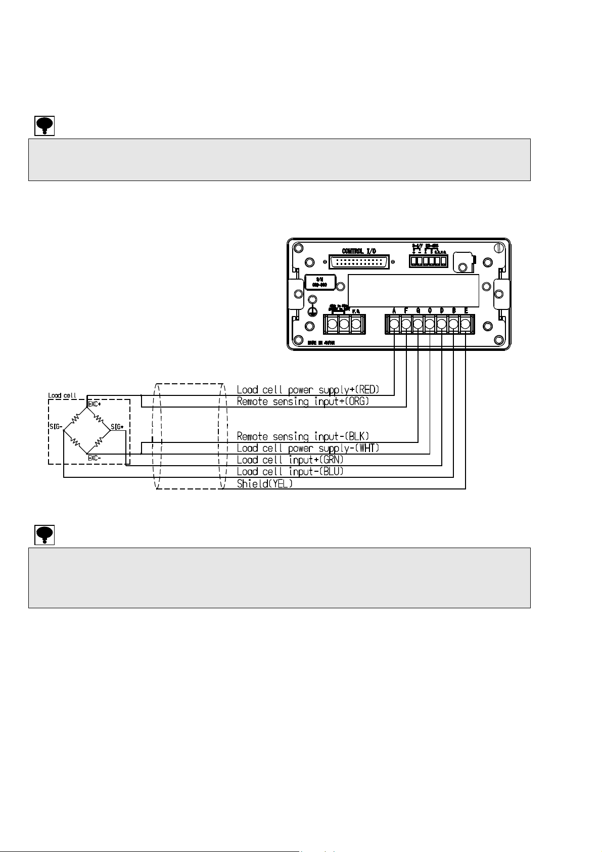
2-2. Connection with strain gage applied transducer
The instrument can connect with the strain gage applied transducers, such as load cells, pressure
sensors, etc. Here, we describe the example of connection with load cells, so that the connection
with another type of strain gage applied transducers shall be preceded in the same way.
When the tension is applied with the use of tension type or universal (tension/compression) type load
cell, and display of (+) direction is required, connect the input (+) of the load cell to the terminal B and
the input (-) of the load cell to the terminal D individually.
(1) Case 6-wires type connection cable
・ When the length of CAB-501 (our standard cable) is more than 100 m totally, there may have the
・ Shorten the remote sensing input + and remote sensing input – near the main body of load cell.
case that accuracy is out of warranty as the remote sensing function of the instrument does not
work enough due to the resistance of the cable.
However, when the short is made near the instrument, it will not work as the six-wire type.
6
Page 23
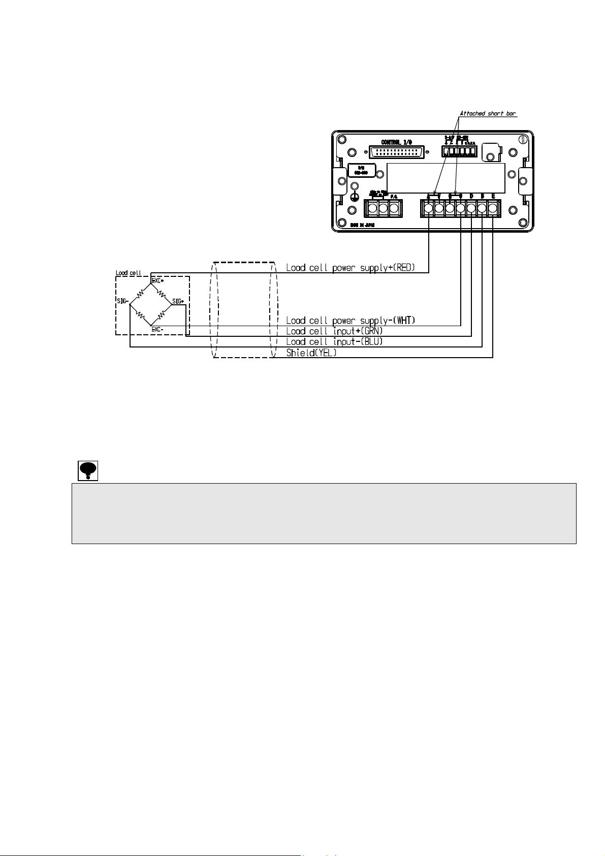
(2) Case 4-wire type connection cable
・ As using the 4-wire cable, shorten the load cell terminals A - F and C - G with the attached shor t bar.
・ When the length of CAB-502 (our standard cable) is more than 30 m totally, there may have the case
CSD-903 does not work in normal operation when the terminal F and G is in the open status.
that the accuracy is out of warranty due to the resistance of cable, the input voltage of the
instrument will be decreased.
7
Page 24
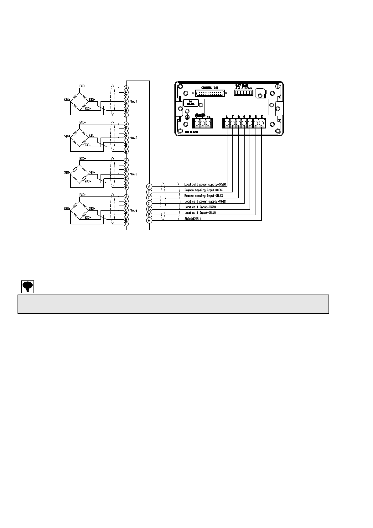
(3) Case connection of the load cells in parallel
The hopper scale, the track scale, etc, have the case to connect with several pieces of the load cells
in parallel. The parallel connections can be easily executed by using optional SB-310 and SB-320
(Summing type junction box).
CSD-903 can make up to 6 parallel connections when the load cell is 350 ohm type. Please consult us
as for a method over 5 parallel connections.
8
Page 25
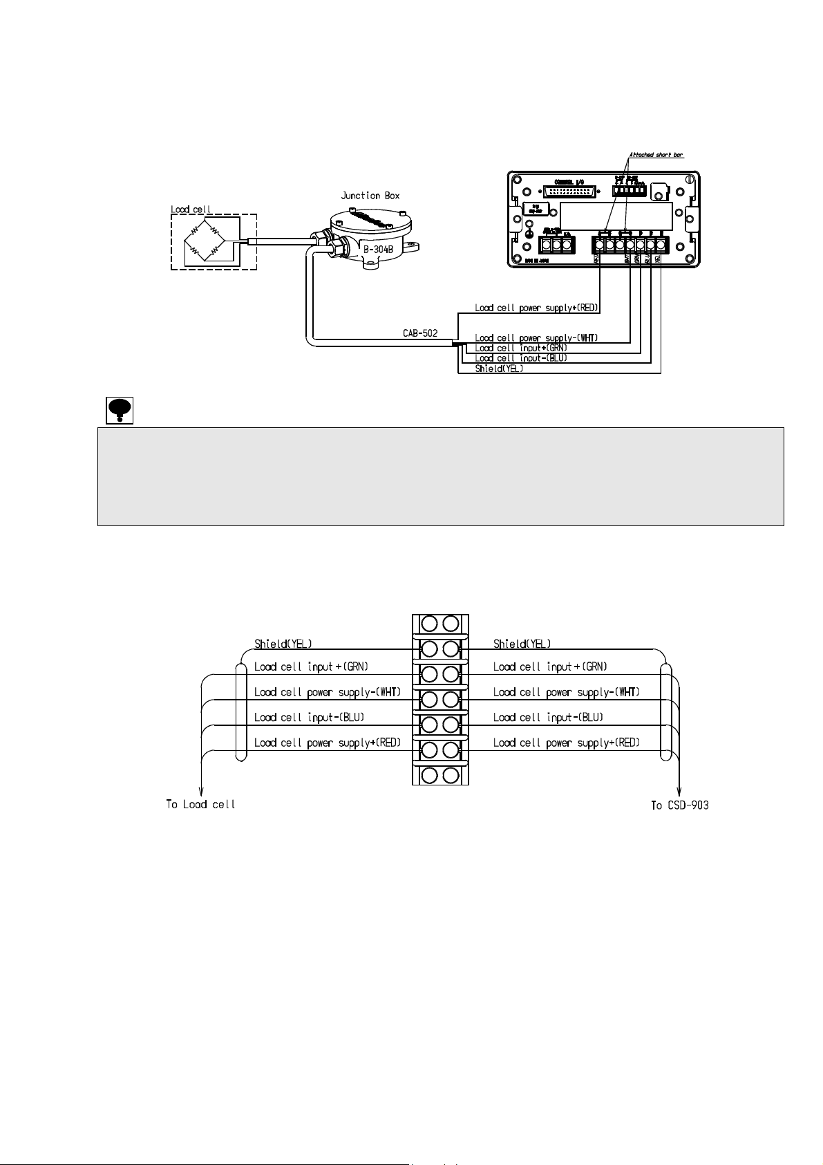
(4) Connecting with load cell, Junction box B-304B for extension, and CSD-903
1) When you use CAB-502 (4 core cable)
・ When you use it with 4 wires method, be sure to make a short-circuited between A-F and between
・ There is the possibility of the descent of the input voltage of the instrument at the time of total 30m
C-G of the load cell terminal board. When terminal F and terminal G are used with opening status,
CSD-903 cannot make normal operation.
or more in length of CAB-502 (our standard cable) and also the possibility of outside of accuracy
due to the resistance of the cable.
B-304B internal terminal connection
9
Page 26
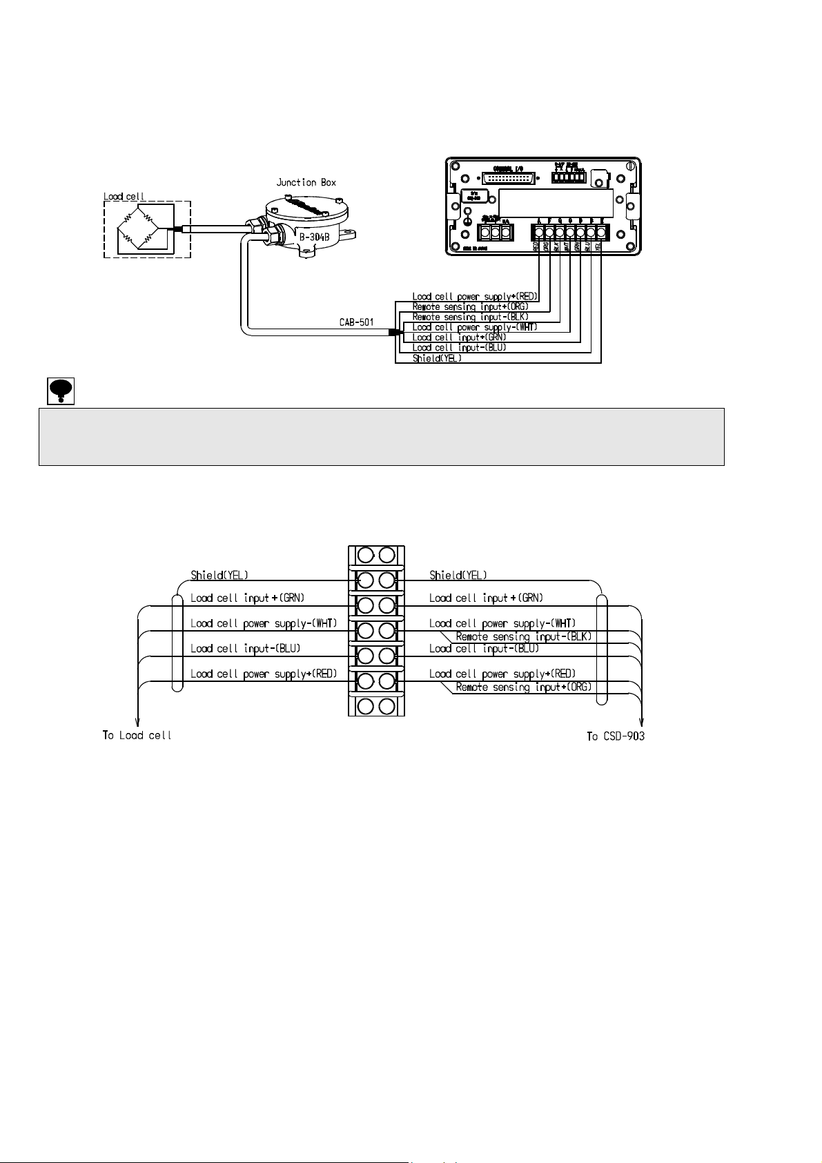
2) When you use CAB-501(6 core cable)
The remote sensing function of the instrument does not function enough due to the resistance of the
cable at the time of total 100m or more in length of CAB-501 (our standard cable), and there may have
the possibility of outside the accuracy guarantee.
B-304B internal terminal connection chart
10
Page 27
r
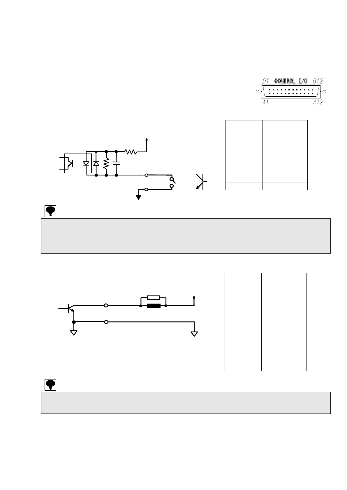
2-3. Connection of external control I/O
The function can be controlled from the outside with the external control I/O connector on the rear
panel.
The external control input is executed by shortening each input and COM.1 with a contact point or
open collector after wiring the connector.
The external control output is executed by open collector output.
(Open collector rated: V
The right figure is an external control I/O connector.
The upper line from A1 to A9 is for input signal, and the lower line
from B1 to B12 and A12 is for output signal.
(1) Connection for input
430ohm
・ There are a pulse input and a level input in the recognition of the external control input signal
depending on setting items.
・ Refer to [8-13-1.Seting method of the external control input] for the details.
・ The common of the external control input and the common of the 2 wire serial interface circuit are
common.
(2) Connection for output
B1 to B12, A12
A11
COM.2
Open collector rated:
=DC35V IC=DC40mA
V
CE
= DC35 V, IC = DC40 mA at maximum.)
CE
Approx. 12V
2.2 k-ohms
0.047μF
A1 to A9
A10
COM.1
Surge elimination device
Load
o
Applicable connector :
Connector FCN-361J024-AU,
Connector cover FCN-360C024-B (made by Fujitsu)
V
CE
A1 Input1
A2 Input2
A3 Input3
A4 Input4
A5 Input5
A6 Input6
A7 Input7
A8 Input8
A9 Input9
A10 COM. 1
B1 Output1
B2 Output2
B3 Output3
B4 Output4
B5 Output5
B6 Output6
B7 Output7
B8 Output8
B9 Output9
B10 Output10
B11 Output11
B12 Output12
A12 Output13
A11 COM. 2
・ The common of the external control output is insulated from the other commons.
・ Refer to [8-13-2. Setting method of the external control output] for the details.
・ Connect a suitable serge elimination device for load for protection from external control output.
11
Page 28
A
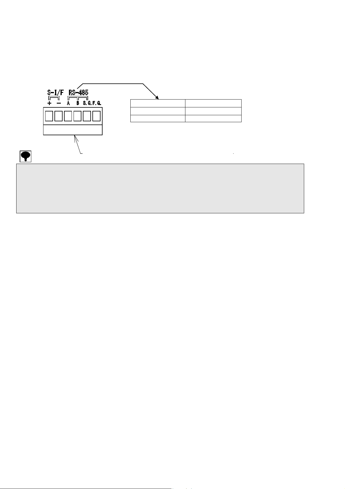
2-4. Connection of standard RS-485 interface
Connect with A, B and S.G. on the output terminals for RS-485 interface and the 2 wire serial
interface showing as below figure. Refer to [14-4.Connecting method] as to the connection.
With the standard RS-485, either the command mode or the protocol conforming to the Modbus is
selectable.
(Refer to [15.Modbus communication] as to the Modbus communication.)
・ Stripped length of electrical cable tip is 7 mm.
・ The tightening torque of terminal screws on the terminal block is 0.6 N・m.
・ Please use AWG28 ~ AWG16 for connecting cable.
・ The signal ground of standard RS-485 interface and internal common are connected.
・ Please connect the shield with F.G. terminal of RS-485 interface / 2-wires method serial interface
terminal by using the shielded cable when CSD-903 complies with the CE conformity or applied JIS
standard.
Screw side of terminals
A
B
S.G. Signal ground
pplicable Plug : XW4B-06B-H1.made by OMRON.
Differential I/O (+)
Differential I/O (-)
12
Page 29
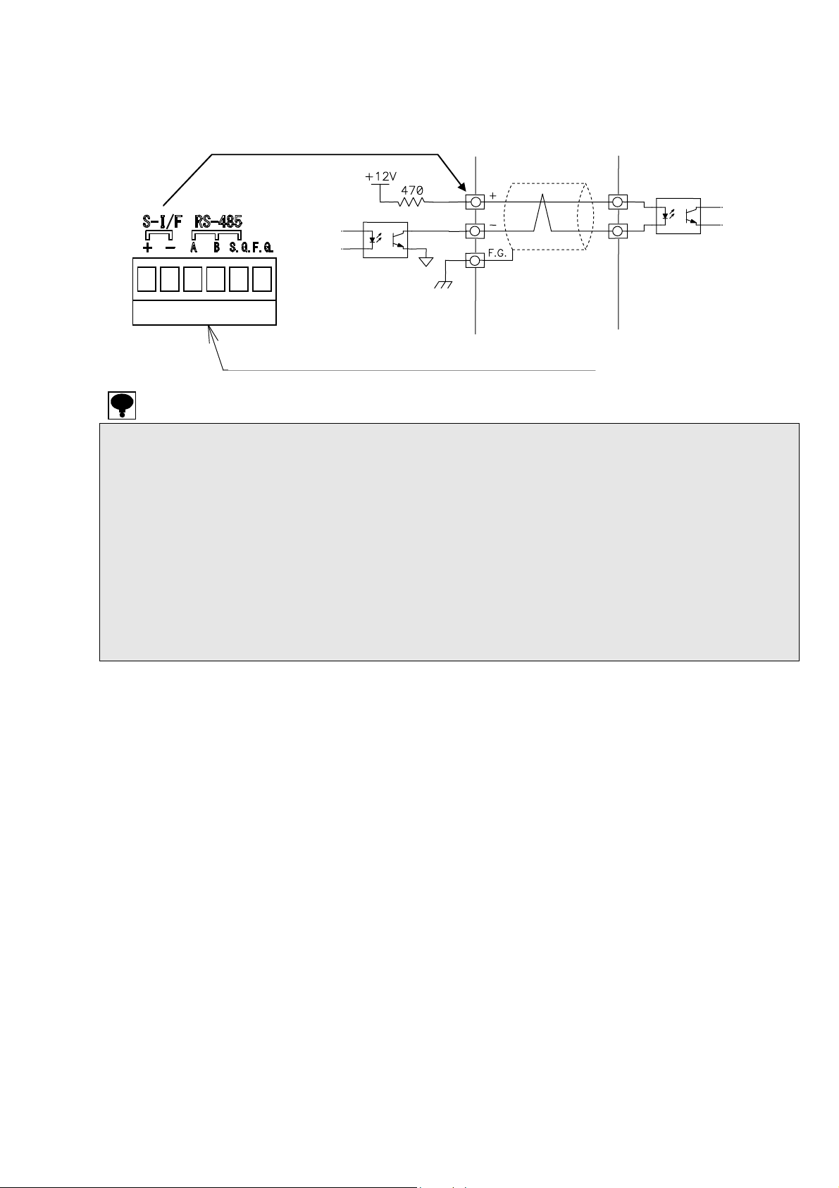
A
2-5. Connection with 2-wires Serial interface
This is the 2-wires method serial interface to connect with a printer, an external display unit, etc.
The 2-wires serial interface is connected with +, - and F.G. shown in the below figure.
CSD-903Internal
equivalent circuit
・ Stripped length of electrical cable tip is 7 mm.
・ The tightening torque of terminal screws on the terminal block is 0.6 N・m.
・ Please use AWG28 ~ AWG16 for connecting cable.
・ There are M252B, etc., made by UNIPULSE as the equipment for the 2-wires method serial interface.
・ The cable must use two cores shielded cable as much as possible and connect the shield with F.G.
・ The equipment for 2-wires method serial interface can be connected up to three in parallel.
・ The commons of the external control input and the 2-wires method serial interface are connected.
・ This internal circuit and photocoupler are insulated.
・ Please connect the shield with F.G. terminal of RS-485 interface/2-wires method serial interface
terminal. Please twist the cable when you don’t use the shielded cable.
(The applicable cable length is up to 100 m with shield, and up to 20 m without shield.)
(Maximum output current : Approx. DC20 mA)
terminal by using the shielded cable when CSD-903 complies with the CE conformity or applied JIS
standard.
Screw side of terminals
pplicable plug : XW4B-06B-H1 (made by OMRON)
Serial interface corresponding equipment
13
Page 30
2-6. Connection with power supply and ground
Connect the power supply with the power supply terminal board on the rear panel of the instrument
shown as below figure.
Grounding should be the D class with the single earth.
Connection with the power supply and the earth should be made surely according to the figures, and
also within the specified power supply condition.
・ The grounding of the instrument should be the D-class with single earth.
・ When suiting the instrument with the CE conformity standard or JIS standard, please make the
Warning
It may cause an unexpected malfunction due to the effects of noise from other equipments.
single earth with a protective ground terminal.
14
Page 31

y
3. Operation
3-1. Changeover of mode
This unit has various modes according to the operating situation.
Change the mode by the key operation.
Stand-by condition
(Light off the measuring value
Set mode 1
Display of
Display of
Display of
Set mode 2
Display of
Display of
Displa
Display of
of
Power ON
Display check
(All light on)
Mesurement mode
(Display measuring value)
+
①Refer to the C function mode
②Refer to the Calibration mode
③Refer to the Check mode
④Refer to the Function mode
⑤Refer to the SQ Function mode
⑥Refer to the setting mode of
weighing comparative value
⑦Refer to the Accumulation
display mode
When the load cell output exceeds ±10 % of weighing capacity in the condition that power-on-zero is
valid after checking the display, the display becomes the error indication of [ ‐‐‐‐‐‐ ]. At this time, if
the key is pressed, the display compulsorily becomes a load display. Refer to the paragraph [6-8.
Power on zero].
15
Page 32

(1) C function mode ( )
Various functions which relate to calibration by setting C function data become effective.
(2) Calibration mode ( )
By setting the calibration data, the calibration is executed to display the electric signal from the
measuring section (load cell) as an accurate load.
(3) Check mode ( )
The ROM version, the each input/output operation, the monitor of load cell output value, the BCD
output and the analog output can be confirmed by the check mode.
(4) Function mode ( )
Various functions become effective because of setting the function data.
(5) SQ function mode ( )
The setting of SQ function data makes various functions related to the sequence operation effective.
(6) Weighing comparative mode ( )
Execute the setting of comparison value of various weighing in the sequence weighing and
comparison operation.
(7) Accumulation display mode ( )
The accumulation value and accumulation times can be confirmed for each brand.
Pressing the key clears the accumulation value and accumulation times displayed.
16
Page 33

4. Calibration
To be able to display the electrical signal from the measuring section (load cell) as an accurate
weight, the operation to match the display of the instrument with the weight loaded on the
measuring section is called a calibration.
For example to adjust the display of this instrument to 100.00 accurately when the weight of 100
kg is loaded on the measuring section is said.
4-1. Set items required in the calibration
(1) Scale interval ( , , , , , )
It is the minimum unit of the measuring value the value to be set is [1], [2], [5], [10], [20] or [50].
The value of {Weighing capacity/Scale interval} is the display resolution.
(2) Weighing capacity ( )
It is the maximum weight to be able to measure by the measuring section (load cell).
(3) Mass of weight used at the span calibration ( )
The span calibration can be executed with the arbitrary weight. The same setting as the weighing
capacity is executed when there is a weight for weighing capacity.
Please give setting here as 2/3 or more of weighing capacity to reduce the calibration error.
(4) Calibration at zero ( )
It is a procedure of the calibration to become the zero point of the measurement when nothing is put
on the measuring section (status of an initial load). There are [Method by the weighing data (status of
an initial load)] and [Method by a numeric input of the load cell output voltage] as a calibration
method.
(5) Calibration at span ( )
It is a procedure by which execute the calibration of the change in the electric signal of the load cell
when the weight is put on the measuring section to become the display of a correct weighing value.
There are [Method with weight] and [Method by a numeric input of the load cell output voltage] as a
calibration method.
4-2. Procedure set if necessary after calibration
(1) Display position of decimal point (C function : )
The decimal point is put on the load display of this unit.
(2) Unit (C function : )
The unit is put on the load display of this unit.
(3) Digital linearize ( )
It is a function the compensation of three points or less except the zero and span, and to reduce the
measurement error. Refer to the paragraph 4-5. Digital linearization.
(4) Automatic range switch (C function : ~ )
It is the setting of the second range or the third range for [Multi scale interval scale]. The boundary
value and the scale interval within the each range are set. Refer to the [6-13.Automatic range switch].
(5) Gravity acceleration compensation (C function: , )
It is a function for the compensation of the span error by setting the gravity acceleration of the two
different districts with a calibration place and a place to be used. Refer to [6-11.Gravity acceleration
compensation].
・ Please execute the calibration if necessary when the environment to be used changes .
・ The display resolution that the performance becomes effective is 10 000 or less.
・ The mass of the weight used in the span calibration must use the one of 2/3 or more of weighing
The display resolution is a value into which weighing capacity is divided by the scale interval of the
first range.
capacity to reduce the calibration error.
17
Page 34

4-3. Calibration procedures
4-3-1. Flow of calibration
Step1 Connect the load cell with this instrument.
Step2 Please energize.
Step3 Please set the bridge power supply.
Step4 To stabilize this unit and the measuring section (load cell); please
make the instrument to the status of energizing for about 10 min.
Step5 Please switch the mode to the calibration mode.
Step6 Please set the scale interval.
Step7 Please set weighing capacity.
Step8 Please set the mass of the weight put on the measuring section.
Step9 Please execute the calibration of the zero point with nothing put on
the measuring section, or by setting the output voltage value of the
zero point of the load cell.
Step10 Please executes the calibration of span by putting the weight on the
measuring section, or by setting the output voltage value of the
span point of the load cell.
Step11 Please quit from the calibration mode. Process the setting since
step 12 showing as follows if necessary.
Connection with load cell
Energizing power supply
Paragraph 6-5
Set the bridge power supply.
Energy for 10 min after
power is turned on.
Paragraph 4-3-2
Switch to the calibration
mode
Paragraph 4-3-3
Set the scale interval
Paragraph 4-3-4
Set the weighing capacity
Paragraph 4-3-5
Set the mass of the weight
Paragraph 4-3-6
Calibration at zero point
Paragraph 4-3-7
Calibration at span
Paragraph 4-3-8
Quit the calibration
Step12
to Paragraph 6-1
Set the display
position of
decimal point
Step13 Step14 Step15
to Paragraph 6-4
Set of the unit
to Paragraph 4-5
Digital linearize
to Paragraph 6-12
Automatic range
switch
Step16
to Paragraph 6-11
Gravity
acceleration
18
Page 35

4-3-2. Switch to the calibration mode
Stand-by condition
Change from the standard measurement mode to the
stand-by condition by the key.
+
Calibration mode
Move to the setting of the scale interval.
4-3-3. Set of the scale interval
Pressing the key with the key pressed, it
displays .
Press the key here.
displays.
Press the here.
displays and it enters into the calibration
mode.
When key is pressed twice from
display, is displayed.
[ ] is the scale interval being memorized now.
Please select the scale interval from 1, 2, 5, 10, 20 or 50.
: Selects the scale interval.
: Setting is interrupted and returns to CCAL
display.
The scale interval to
be used
: The displayed value is memorized, and proceed
to the next step.
Move to set weighing capacity
Press the key after the set.
19
Page 36

g
p
p
4-3-4. Set weighing capacity
Memorized weighing
Memorized weighing
ca
acity
When key is pressed from display,
is displayed.
When the weighing capacity has already been changed, the
weighing capacity being memorized now is displayed.
Here, please set the weighing capacity.
Changed weighing
Changed weighing
acity
ca
Move to setting the mass
of the weight.
4-3-5. Setting the mass of the weight
Mass amount equal to
ひょう量分の分銅値
wei
hing capacity
Weight value put on
measurement section.
: The value of changed digit is changed.
: Changed digit is selected.
: The value is changed to [0].
: Setting is interrupted and display returns to CCAL.
: The display value is memorized, and it proceed to the
next step.
After the setting, press the key.
When key is pressed from display
****
****
[ ] is the amount of weighing capacity.
is displayed.
Please set the mass of the weight actually put on the measuring
section here.
The same setting as the weighing vcapacity is executed when
there is a weight for weighing capacity.
: The value of changed digit is changed.
: Changed digit is selected.
: The value is changed to [0].
: Setting is interrupted and display returns to CCAL.
: The display value is memorized, and it proceed to the
next step.
Move to the calibration
of zero point
After the setting, press the key.
20
Page 37

V/VmV/V
4-3-6. Calibration of zero point
When the zero calibration starts, is displayed.
Please select the zero calibration method.
(1) Method by the measuring data (status of initial load) ⇒ Press the key, and execute the
operation of a).
Execute the calibration of zero with nothing put on the measuring section.
(2) Method by the numeric input of the load cell output voltage. ⇒ Press the key, and execute the
operation of b).
Execute the calibration of zero with inputting the output voltage value of the load cell when nothing is
put on the measuring section.
Press the
key,
with nothing on
the measuring
section.
a) Method by the measuring data (status of
initial load)
Please make that nothing is put on the
measuring section.
Press the key when
display blinks, and the STABLE mark lights. The
zero point is memorized, and is
displayed.
b) Method by the numeric input of load cell
output voltage.
Under the
calibration
of zero.
Press the
key,
after STABLE
mark lights on.
Error display in the calibration of zero point
Memorized load cell output voltage.
Set output voltage of the load cell.
Move to the calibration of span.
m
When key setting is pressed,
is displayed, and when
key is pressed, is displayed also.
[ ] is the memorized output voltage
of the load cell. Please set the load cell output
voltage in mV/V scale which correspond to the
zero point of the measurement.
: The value of changed digit is
changed.
: Changed digit is selected.
: The displayed value is changed to [0].
: Setting is interrupted and display
returns to CCAL.
: The display value is memorized, and
it proceed to the next step.
After the setting, press the key.
: The display blinks for about two seconds when the output of the load cell is
-2.5 mV/V or less. (Refer to the paragraph 19. Error display)
: The display blinks for about two seconds when the output of the load cell is
2.5 mV/V or more. (Refer to the paragraph 19. Error display)
21
Page 38

M
/
/
der
4-3-7. Calibration of span
When the span calibration starts, is displayed.
Please select the span calibration method.
(1) Method by the measuring ⇒ data Press the key, and execute the operation of a).
Execute the span calibration with weight put on the measuring section.
(2) Method by the numeric output of the load cell output ⇒Press the key, and execute the
operation b).
Execute the span calibration by inputting the value which subtracts the output voltage of the load cell
to zero point of measurement set in paragraph 4-3-6. From the output voltage corresponding to the
mass of the weight set in paragraph 4-3-5.
key is
pressed with
the weight put
on the
measurement
section.
a) Method with weight
Please put the weight corresponds to mass set
in the paragraph 4-3-5 on the measuring
section.
Please press the key when
display blinks, and the STABLE
mark lights. Span is memorized and
is displayed.
b) Method by the numeric input of load cell
output voltage.
When key is pressed, is
the
Un
calibration of
span.
Press the
key
after the
STABLE mark
lights on.
emorized output
voltage of the loa d ce ll.
is displayed also.
[ ] is the memorized output voltage
displayed, and when key is pressed,
mV
V
of the load cell. Please set the value in mV/V
scale which subtracts the output voltage of the
load cell to zero point of measurement from the
output voltage corresponding to the mass of the
Se t outpu t vo ltage of
the load cell.
weighing capacity.
: The value of changed digit is
changed.
mV
V
: Changed digit is selected.
: The displayed value is changed to
zero.
: Setting is interrupted and display
returns to CCAL.
: The display value is memorized, and
it proceeds to the next step.
After the setting, press the key.
Error display in the calibration of span
: The display blinks for about two seconds when ([Load cell output voltage at span]-
[Load cell output voltage at zero point]) ≦ 0.0 mV/V.
(Refer to the paragraph 19. Error display)
: The display blinks for about two seconds when load cell output is 3.1 mV/V or more.
(Refer to the paragraph 19. Error display)
22
Page 39

4-3-8. Quit the calibration
Stand-by condition
Please set the fine adjustment of ZERO and SPAN, digital linearize, ZERO set and Tare weight
cancellation after the finish of calibration. Those data is cleared if you process the calibration again.
Press the key to quit the calibration mode.
The display becomes , and the set data is
memorized internally.
Press the to set to the stand-by condition.
The calibration mode is completed.
is displayed when span calibration is completed.
23
Page 40

p
4-4. Fine adjustment of zero and span
It is the function to make the fine adjustment of zero and span when there is a difference between
the actual measuring value and the weight.
4-4-1. Changeover to zero and span fine adjustment mode
Measurement mode
Stand-by condition
+
Fine adjustment mode of
zero and span
Press the key, and move from a usual measurement
mode to the stand-by condition.
When key is pressed with key, is
displayed.
Press the key here.
By pressing the key, is displayed, then it
enters into the fine adjustment mode of zero and span.
is displayed, then key is pressed.
is displayed.
Move to the fine
adjustment mode of
zero and s
an.
24
Page 41

4-4-2. Fine adjustment of zero and span
When key pressed from display,
is displayed.
In executing the zero fine adjustment, proceeds the operation of
a).
In case of executing the span adjustment only, press key,
and proceed the operation of b) after displaying .
a) Fine adjustment of Zero
Press the key. Display becomes .
[ ] is the present measuring value, and it can be displayed
up to 1/10 digit.
Ex. Without a decimal point 0 ~ 6000 -> 0.0 ~ 6000.0
With a decimal point 0.0 ~ 600.0 -> 0.00 ~ 600.00
Please set the display to [zero] after the condition which nothing is
put on the measuring point.
: Increase the measuring value.
Increase continuously by keeping the key pressed.
: Decrease the measuring value.
Decrease continuously by keeping the key pressed.
: Interrupts the setting, and returns to
display.
: Memorizes the display value, and proceed to the next
step.
After the zero fine adjustment, press the key.
Display becomes . in case of executing the fine
adjustment of span, precedes the operation of b).
Otherwise, press the key, and proceed the operation of c)
after displaying .
b) Fine adjustment of span
Put the weight which can be put on the measuring section under
the weighing capacity.
is displayed by pressing the key.
[ ] is the present measuring value, and it can be
displayed up to 1/10 digit.
Please set the display to become the same value with the weight
put on the measuring section.
After the fine adjustment of span, proceeds the operation of c)
after the display by pressing key.
[A]
[B]
25
Page 42

[A]
[B]
c) End of fine adjustment mode
Press the key to quit the fine adjustment mode of zero and
span.
the internal memory.
Press the key, and move to the stand-by condition.
The fine adjustment mode of zero and span is completed.
displayed, and the setting data is memorized to
26
Page 43

p
p
4-5. Digital linearize.
After the calibration, the measurement error of some scale interval levels might be caused between
the zero and span (weighing capacity) by the influence of the measuring section etc.
The digital linearization function executes the compensation of three points or less except the zero
and span, and to reduce the measurement error.
D
i
s
p
l
a
y
Error
0
Zero
Before linearization
4-5-1. Changeover to digital linearization mode
Measurement mode
Span
Weight value
D
i
s
p
l
a
y
0
Zero
Correction
Correction
After linearization
oint 1
Span
Correction point 3
oint 2
Wheight value
Make the condition from the normal measurement
mode to the stand-by condition by pressing the
Stand-by condition
+
Digital linearization mode
Move to the digital linearization mode.
key.
Press the key with pressing the key,
is displayed.
Press the key after pressing the key ,
is displayed.
is displayed after pressing the
key twice, and enter into the digital
linearization mode.
27
Page 44

4-5-2. Setting of the digital linearization
Put the weights.
By pressing the key twice from
display, is displayed. As the display
Becomes → by
pressing the key, please select the numbers of
points which wants to compensate linearization, and
press the key
: compensation by 1 point
: compensation by 2 point
: compensation by 3 point
Please put the weight of the point which should be the
compensation after the display becomes
on the measuring section and press the key.
As the measuring value blinks, press the key
after confirming the stability mark (▼) lighting on.
As the 100 digit of the measuring value blinks, set to
Confirm the stability mark
lighting on.
the same value with the weights put on the measuring
section.
:Increase the measuring value.
:Decrease the measuring value.
When P-1 is selected.
:The displayed value is memorized, and proceed
to the next step.
Put the weights.
:The setting is interrupted, and return to the
display of .
The display becomes when
Confirm the stability mark
lighting on.
compensation of the second point.
Additionally, the display becomes
when is selected, and please execute
the compensation of the third point.
When P-2 is selected
Please make the value of weight as
< < .
[A]
[B]
is selected, and please execute the
28
Page 45

When P-3 is selected.
[B][A]
Put the weight.
Confirm the stability
mark lighting on.
Please press the key when the compensation of
each point is completed.
Press the key to complete digital linearization
mode.
memorized in the internal memory.
Please set to the stand-by condition by pressing the
key.
The digital linearization mode is finished.
is displayed.
is displayed, and the setting data is
・ Please make the weights to be compensated as < < .
・ The linearization compensation cannot be executed over the weighing capacity.
・ Please refer [19-1. Error load display] as to the details of error display.
・ The compensation data of the digital linearization can be cleared by C function CF-98.
Please refer to the paragraph [6-15. Digital linearization clear].
29
Page 46

4-6. Calibration only of zero point
It is a function for the re-calibration only of the zero point when the amounts of the tare other than
the weighing capacity of the measuring section are changed.
4-6-1. Changeover of the calibration mode by zero point
Measurement mode
Stand-by condition
+
Calibration mode only of zero point
Press the key to change from the measurement
mode to the stand-by condition.
key.
pressing the key.
times, and entered into the calibration mode only of the zero point.
is displayed when the key is pressed with the
is displayed by pressing the key after
is displayed after pressing the key at three
30
Page 47

Calibration mode only of zero point
Please make the display to by pressing
the key from the display of .
Please make to the status where nothing is put on the measuring
section here excluding the tare outside weighing capacity.
The display of blinks by pressing the key,
and start the calibration at zero.
Press the key after the stability mark lighting on.
The calibration of zero point is completed, and is
displayed.
Press the key to finish the calibration mode only of zero
point.
the internal memory.
is displayed, and the setting data is memorized in
Please set to the stand-by condition by pressing the key.
The calibration mode only of zero point is finished.
Error display in the calibration of zero point
-2.5 mV/V.
(Please refer to the paragraph 19. Error display.)
(Please refer to the paragraph 19. Error display.)
: The display blinks for about 2 seconds when the load cell output is less than
: The display blinks for about 2 seconds when the load cell output is over 2.5 mV/V.
31
Page 48

4-7. LOCK of calibration
The function change in the calibration and C function can be prohibited by the switch of rear panel.
4-7-1. LOCK by the switch
There is calibration LOCK switch inside when the cover at the right of terminals of RS-485 interface
and 2-wires type serial interface in the rear panel.
LOCK ON
LOCK OFF
Calibration Lock switch
Calibration Lock switch cover
Installation screw
For calibration Lock switch cover
・ When the calibration LOCK is at the effective, the mode of [ ] or [ ] cannot be used.
・ When the calibration LOCK is at the effective, the rewriting C function data by communication and
the communication calibration is cannot.
32
Page 49

5. C function mode
The various functions concerning to the calibration become effective by setting the C function
data.
5-1. Setting method of C function data
Measurement mode
Stand-by condition
+
Press the key to change the condition from normal
measurement mode to stand-by condition.
When the key is pressed with pressing the key,
By pressing the key, is displayed.
Please select C function number which wants to change.
: The value of the changed digit is changed.
: Select the changed digit.
: Change the display value to [0].
: Return to the display of .
: Memorize the display value, and proceed to the next
step.
: Finish the C function mode without changing all setting.
By pressing the key, please change the setting value of
selected C function mode.
is displayed.
By pressing the key. The changed content is registered, and
the following changed C function number is displayed on the
Registration is
completed.
panel.
Please select the changed C function number when you
continuously change the setting of the other C function numbers.
By pressing key is pressed after the registration is
completed, is displayed.
By pressing the key, set to the stand-by condition.
33
Page 50

5-2. Function of C function data
Item Function No. Setting value Contents
Display position of
decimal point.
A/D sampling rate CF-02 0 20 times/s
Condition of over display CF-03
Unit CF-05
Excitation CF-07
Net weight sign inversion CF-08
Operating condition of
zero set
Effective range of zero
set
Target of zero tracking CF-12 0 Gross value and net value ( for load display )
Data width of zero
tracking
Time width of zero
tracking
Operation of power-onzero
Operating condition of
tare weight cancellation
Change of data stored
place
Power on clear CF-18
●: Has been set as default
CF-01
●0
No decimal point
1 1234.5
2 123.45
3 12.345
4 1.2345
●1
0
1
●2
●0
200 times/s
Bigger than |Weighing capacity +9D|
Exceeding to the weighing capacity ±110%
Smaller than -20D and larger than weighing
capacity +9D
No unit
1 g
2 kg
3 t
4 lb
5 N
6 kN
●0
DC10 V
1 DC5 V
2 DC2.5 V
●0
Net weight sign not inverted
1 Net weight sign inverted
CF-10 0 Operation when it is steady
●1
CF-11 00 ~ 30
Operation by unconditional
Unit : ±1 % of the weighing capacity
●02
●1
CF-13 00 ~ 99
●01
CF-14 00 ~ 99
●00
CF-15
●0
Gross value ( only at gross value display )
Unit : 0.1 D
00 : Zero tracking OFF
Unit : 0.1 s
00 : Zero tracking OFF
Invalid
1 Valid
CF-16
CF-17
●0
1
2
3
●0
Operation when it is steady and 0 < GROSS
≦ Weighing capacity
Operate unconditionally and 0 < GROSS ≦
Weighing capacity
Operation when it is steady and 0 < GROSS
≦ |Weighing capacity|
Operate unconditionally and 0 < GROSS ≦
|Weighing capacity|
RAM
1 EEPROM
0:Invalid
1:Valid
000~111
●000
1
10
digit:Data of tare weight cancellation
2
10
digit:Data of preset tare weight
cancellation
3
10
digit:Data of zero set and zero tracking
34
Page 51

Item Function No. Setting value Contents
Stability detection while the set
CF-20
mode 2 or set of preset tare
Unit display in sub- display section
CF-21
while the set mode 2 or set of preset
tare
Method of setting gravity
CF-25
acceleration compensation
District number of using place CF-26
01 ~ 16 Unit : District
(Possible to set
at CF25 = 0)
District number of calibration place CF-27
01 ~ 16 Unit : District
(Possible to set
at CF25 = 0)
Gravity acceleration value setting of
using place
CF-28
(Possible to set
9.000 ~ 9.999
●9.797
at CF25 = 1)
Gravity acceleration value setting of
calibration place
CF-29
(Possible to set
9.000 ~ 9.999
●9.797
at CF25 = 1)
Range switch operation CF-40
Set of scale interval of the second
CF-41 0 1 scale interval
range
Boundary value setting in the
second range
Set of scale interval of the third
CF-42 000000 ~ 999999
●003000
CF-43 0 1 scale interval
range
Boundary value setting in the third
range
CF-44 000000 ~ 999999
●006000
Analog output target CF-70
Display value at the analog output
of DC4 mA(DC0 V)
Display value at the analog output
of DC20 mA(DC10 V)
Calibration data of the maximum
CF-71 -999999 ~ 999999
●000000
CF-72 -999999 ~ 999999
●010000
CF-90
capacity (Reference use)
Calibration data of weighing
CF-91
●10000
capacity (Reference use)
●Has been set as default
●0
Invalid
1 Effective
●0
Invalid
1 Effective
●0
Set the district number
1 Set the numerical value of gravity
acceleration
●10
●10
Unit : m/s2
Unit : m/s2
●0
Range change OFF
1 Changeable two ranges
2 Changeable three ranges
1 2 scale interval
2 5 scale interval
●3
10 scale interval
4 20 scale interval
5 50 scale interval
1 2 scale interval
2 5 scale interval
●3
10 scale interval
4 20 scale interval
5 50 scale interval
●0
Display interlock
1 Gross value
2 Net value
Unit : 1D
Unit : 1D
●1
35
Page 52

Item Function No. Setting value Contents
Calibration data of the weight
(Reference use)
Calibration data of zero
mV/V (Reference use)
Calibration data of span
mV/V (Reference use)
Stability detection time width
at calibration
CF-92
CF-93
CF-94
●10000
●0.00000
●0.30000
CF-97 00 ~ 99
●05
Unit : 0.1 s
00 : OFF of stability detection at calibration
Digital linearization clear CF-98 The data of the compensation by the digital
linearization is cleared.
Memory clear CF-99 C function set content is returned default
setting.
●Has been set as default
36
Page 53

6. Various functions by C function data
6-1. Setting of decimal point display position
The decimal point display position is selected by C function CF-01.
The position of the decimal point can be selected from [Nothing], [1234.5], [123.45], [12.345] or
[1.2345].
Default is set to [Nothing].
6-2. A/D sampling rate
The A/D sampling rate is selected by C function CF-02
The A/D sampling rate can be selected from [200 times/s] or [20 times/s].
Default is set to [200 times/s].
The A/D sampling rate decreases temporarily while writing the changed data of set value in EEPROM.
6-3. Condition of over display ( or display)
The over display condition is selected by C function CF-03.
[At the time of more than |weighing capacity + 9D|], [at the time of exceeding to the weighing
capacity ±110 %] or [Exceeding to -20D to weighing capacity] can be selected.
Default is set to [Smaller than -20D and larger than weighing capacity +9D].
6-4. Unit
The unit is selected by C function CF-05.
The unit can be selected from [No unit], [g], [kg], [t], [lb], [N] or [kN].
Default is set to [No unit].
6-5. Excitation
Excitation is selected by C function CF-07.
The voltage (DC) excited to the load cell can be selected from [DC10 V], [DC5 V] and [DC2.5 V].
Default is set to [DC10 V].
When CSD-903 is applied for the system where zener barrier is used, apply it by selecting the
excitation properly according to the below table.
System configuration Excitation
10 V 5 V 2.5 V
1 point of load cell + zener barrier
2 points of load cell + Summing type junction box + zener barrier
3 points of load cell + Summing type junction box + zener barrier
4 points of load cell + Summing type junction box + zener barrier
5 points of load cell + Summing type junction box + zener barrier
6 points of load cell + Summing type junction box + zener barrier
The above are the examples when CAB-501 (6-cores) type of cable and 350 Ω type of load cell
are applied.
× ○ ○
× × ○
× × ○
× × ○
× × ○
× × ×
○ : Applicable. × : Not Applicable.
37
Page 54

6-6. Net weight sign inversion
The net weight sign inversion function is used to invert the sign of the net weight display and net
weight data output externally, for example, in simple comparison discharging mode.
The net weight sign inversion function is a function for making the net weight display or net weight
data output externally positive by inverting the sign of the net weight using C function CF-08.
Net weight sign inversion can be selected from [Net weight sign not inverted] or [Net weight sign
inverted].
Default is set to [Net weight sign not inverted].
6-7. Zero set
The zero set function memorizes a present measuring value as zero point and adjusts the display to
zero by pressing the key when the indicated value of the load display section is the gross value
and at the same time Zero set effective range.
6-7-1. Operating condition of zero set
The operating condition of zero set is selected by C function CF-10.
The effective range is common for both of zero set and zero tracking.
[Operation at steady] or [Unconditional operation] can be selected.
Default is set to [Operation at steady].
6-7-2. Zero set effective range
The effective range of zero set is selected by C function CF-11
Setting range: 00 – 30 Unit : ±1 % of the weighing capacity, 00: OFF
Default is set to [02].
・ When the zero compensation for the effective range is executed by the zero set and the zero
・ When the tare weight cancellation or the preset tare weight cancellation is executed, zero set shall
tracking, the zero set is not accepted.
be executed after clearing the tare weight cancellation and the preset tare weight cancellation.
38
Page 55
6-8. Zero tracking
The function of zero tracking compensate the gradual zero drift in a constant condition and stabilize
the zero point.
6-8-1. Target of zero tracking
The zero tracking target is selected by C function CF-12.
[Gross value or net value (for load display)] or [Gross value (only at gross value display)] can be
selected. Default is set to [Gross value].
6-8-2. Zero tracking data width
The zero tracking data width is selected by C function CF-13.
Setting range : 00-99, Unit : 0.1 D, 00:OFF
Default is set to [00].
6-8-3. Zero tracking time width
The zero tracking time width can be set by C-function CF-14.
Setting range : 00-99, Unit : 0.1 s, 00:OFF
Default is set to [00].
Ex. The data width to which the zero tracking is executed by C function CF-13 is set.
The zero tracking data width for each set value [n] is obtained in the display conversion by the
following expression.
[Zero tracking data width] = [Set value (n) of CF-13] x 0.5 x [Scale interval]
When the set value of C function CF-13 is [10] and the scale interval is [D = 5], that is
[Zero tracking data width] = 10 x 0.5 x 5D = 25D
+
Zero traching
data width
Zero point
Zero tracking
-
data width
Display
Display
Setting of CF-14
Setting of CF-14
Setting of CF-14
Time
Less than setting of CF-14
・ The zero tracking does not operate when either of setting C function CF-13 or CF-14 is [0].
・ Please do not use the zero tracking when the load vibrates gradually in the vicinity of the zero point.
・ Please note that the zero tracking might become effective even if an actual load change is rapid
when the load change becomes gradual by strength of the digital filter and the stabilization filter.
・ The zero tracking will not be operated when the zero compensation is executed for the effective
range of portion by the zero tracking and zero set.
39
Page 56

6-9. Power on zero
The power on zero function changes the display to zero if the changes of display is within ±10 % of
the maximum capacity when the power is turn on, or in the stable condition in the operation of
display turning on.
6-9-1. The operation of power on zero
The operation of power on zero is selected by C function CF-15.
The power-on-zero operation is selected from [Effective] and [Invalid].
Default is set to [Invalid].
・ The zero compensation is not accepted in the following condition when the setting of C functions
・ When the power on zero is executed, each data of tare weight cancellation, preset tare weight
CF-15 is [Effective power on zero] and when power on zero is starting.
(1) When the display is not a stable condition, it becomes as all lighting.
(2) When the measurement value exceeds ±10 % of the weighing capacity, [ ‐‐‐‐‐‐ ] is displayed.
At this time, by pressing the key, the display becomes a load value compulsorily.
cancellation, zero set and zero tracking shall be all cleared.
6-10. Tare weight cancellation
By pressing the key, the indication of [TARE] and [NET] in the condition display section is
turned on and the display changes to zero.
To execute the tare weight cancellation clear, press the key when the gross value is zero. The
tare weight cancellation is cleared and [GROSS] of the condition display section lights at the same
time as becoming a gross value display.
6-10-1. Operating condition of tare weight cancellation
The operating condition of tare weight cancellation is selected by C function CF-16.
[Operation when it is steady and 0 < GROSS ≦ WEIGHING CAPACITY],
[Operate unconditionally and 0 < GROSS ≦ WEIGHING CAPACITY],
[Operation when it is steady and 0 < GROSS ≦ | WEIGHING CAPACITY |] and
[Operate unconditionally and 0 < GROSS ≦ | WEIGHING CAPACITY |] can be selected.
Default is set to [Operation when it is steady and 0 < GROSS ≦ WEIGHING CAPACITY]
・ The tare weight cancellation is not accepted when the gross value is larger than the first range.
・ When the tare weight cancellation is executed with a preset tare weight cancellation executed, a
・ When the zero set is executed in the condition of gross value display, the tare weight cancellation
preset tare weight cancellation is canceled, and the tare weight cancellation is executed. (A preset
tare weight cancellation cannot be used together with the tare weight cancellation)
will be cancelled.
40
Page 57

6-11. Clear at power on
Setting of the clear at power on is selected by C function CF-18.
Clear at power on function is clear [Data of tare weight cancellation],
[Data of preset tare weight cancellation] and [Data of zero set and zero tracking] when the power is
turn on, or in the operation of display turning on.
Setting: 000 ~ 111, 0: Invalid, 1: effective, Default: 000
0
: Data of tare weight cancellation
10
1
: Data of preset tare weight cancellation
10
2
10
: Data of zero set and zero tracking
6-12. Setting while set mode 2 or set of preset tare
Proceed to set the unit display in sub-display section and the stability detections in condition display
while the set mode 2 or set of preset tare.
6-12-1. Operation for stability detection
The selection whether the stability detection is effective or invalid is made by C function CF-20.
Default is set to [Invalid].
6-12-2. Operation for unit display in sub-display section
The selection whether the unit display in sub-display section is effective or invalid is made by C
function CF-21. Default is set to [Invalid].
6-13. Gravity acceleration compensation
When the calibration place and the using place of the measuring are different, the error is caused in
span by the difference of the gravity acceleration of the various place districts.
The gravity acceleration compensation function is a function for the compensation of this span error
by setting the gravity acceleration of two districts with a different calibration place and using place.
When the calibration place and the using place are the same, it is not necessary to execute the
gravity acceleration compensation.
6-13-1. Setting method of gravity acceleration compensation
The setting method of the gravity acceleration compensation is selected by C function CF-25.
[The district number is set] or [The numerical value of gravity acceleration is set] can be selected.
Default is set to [The district number is set].
6-13-2. Setting of district number of the using place (When CF-25: 0)
The setting of the district number of the using place is executed by C function CF-26.
The setting of district number: 01 ~ 16
Default is set to 10 districts.
Please refer to [Gravity acceleration compensation table] in the next page.
6-13-3. Setting of district number of the calibration place (When CF-25: 0)
The district number of the calibration place can be set by C function CF-27.
The set of the district number: 01 ~ 16
Default is set to 10 districts.
Please refer to [Gravity acceleration compensation table] in the next page.
41
Page 58

6-13-4. Setting of Gravity acceleration value of the using place (When CF-25: 1)
The gravity acceleration value of the using place can be set by C function CF-28.
Setting range: 9.000 ~ 9.999
Default is set to [9.797].
Please refer to [Gravity acceleration compensation table] in the next page.
6-13-5. Setting of Gravity acceleration value of the calibration place (When CF-25: 1)
The gravity acceleration value of the calibration place can be set by C function CF-29.
Setting range: 9.000 ~ 9.999
Default is set to [9.797].
Please refer to [Gravity acceleration compensation table] in the next page.
< The compensation table of gravitational acceleration (for reference) >
District
No.
1 9.806
2 9.805
3 9.804
4 9.803
5 9.802
6 9.801
7 9.800
8 9.799
9 9.798
10 9.797
11 9.796
12 9.795
13 9.794
14 9.793
15 9.792
16 9.791
Acceleration
(m/s2)
Pertinent district
Kushiro-shi, Kitami-shi, Abashiri-shi, Wakkanai-shi, Monbetsu-shi,
Nemuro-shi,
Branch administrative office jurisdiction of Souya, Rumoi, Abashiri, Nemuro,
and Kushiro.
Sapporo-shi, Otaru-shi, Asahikawa-shi, Yubari-shi, Iwamizawa-shi,
Biubai-shi, Ashibetsu-shi, Ebetsu-shi, Akahira-shi, Shibetsu-shi, Furano-shi,
Nayoro-shi, Mikasa-shi, Chitose-shi, Takigawa-shi, Sunagawa-shi,
Utashinai-shi, Fukagawa-shi, Eniwa-shi,
Branch administrative office jurisdiction of Ishikari, Goboro, Kamikawa, and
Sorachi.
Hakodate-shi, Muroran-shi, Obihiro-shi, Tomakomai-shi, Noboribetsu-shi,
Date-shi,
Branch administrative office jurisdiction of Toshima, Hinoyama, Tanshin,
Hidaka and Tokachi
Aomori-ken
Iwate-ken, Akita-ken
Miyagi-ken, Yamagata-ken
Fukushima-ken, Ibaragi-ken, Niigata-ken
Tochigi-ken, Toyama-ken, Ishikawa-ken
Gunma-ken, Saitama-ken, Chiba-ken, Tokyo(excluding branch
administrative office jurisdiction of Hachijojima, Ogasawara), Fukui-ken,
Kyoto-fu, Tottori-ken, Shimane-ken
Kanagawa-ken, Yamanashi-ken, Nagano-ken, Gifu-ken, Shizuoka-ken,
Aichi-ken, Mie-ken, Wakayama-ken, Shiga-ken, Osaka-fu, Hyogo-ken,
Nara-ken, Okayama-ken, Hiroshima-ken, Yamaguchi-ken, Tokushima-ken,
Kagawa-ken,
Tokyo(Only branch administrative office jurisdiction of Hachijojima),
Ehime-ken, Kochi-ken, Fukuoka-ken, Saga-ken, Nagasaki-ken, Oita-ken
Kumamoto-ken, Miyazaki-ken
Kagoshima-ken (excluding branch administrative office jurisdiction of
Nase-shi and Oshima-gun
Tokyo(Only branch administrative office jurisdiction of Ogasawara)
Kagoshima-ken(Only branch administrative office jurisdiction of Nase-shi
and Oshima-gun)
Okinawa-ken
Confirm the details of the gravitational acceleration by the service of the gravity data on the homepage
of [Science chronology] and Geographical Survey Institute, etc.
(http://vldb.gsi-mc.go.jp/sokuchi/gravity/calc/gravity.pl)
42
Page 59

g
6-14. Automatic range switch
Automatic range switch function switches automatically and displays the scale interval by the
measuring data of the gross or net value by dividing the range of the measurement to the weighing
capacity into 2 or 3.
6-14-1. Setting of the range switch operation
The range switch operation can be selected by C function CF-40.
The range switch can be selected from [OFF (without range switch)], [Two range switch] and [Three
range switch].
Default is set to [OFF].
6-14-2. Setting the scale interval of the second range
The scale interval of the second range can be set by the C function CF-41.
The scale interval can be selected from [1 scale interval], [2 scale interval], [5 scale interval], [10 scale
interval], [20 scale interval] and [50 scale interval]. Default is set to [5 scale interval].
6-14-3. Setting the boundary value of the second range
The boundary value of the second range can be set by C function CF-42.
Setting range: 0 ~ 999999, Default is set to [003000].
6-14-4. Setting the scale interval of the third range
The scale interval of the third range can be set by the C function CF-43.
The scale interval can be selected from [1 scale interval], [2 scale interval], [5 scale interval], [10 scale
interval], [20 scale interval] and [50 scale interval]. Default is set to [10 scale interval].
6-14-5. Setting the boundary value of the third range
The boundary value of the third range can be set by C function CF-44.
Setting range: 0 ~ 999999. Default is set to [006000].
Ex.1 In case of gross value
The first range: 300.0 g (Boundary of the second range),
scale interval 0.1 g (The scale interval in calibration)
The second range: 600.0 g (Boundary of the third range),
scale interval 0.5 g (Scale interval of the second range)
The third range: 1 000.0 g (The weighing capacity),
scale interval 1 g (Scale interval of the third range)
Scale interval 0.1 g
目量 0.1 g
0 g 300 g 600 g 1 000 g
The measurement from 0 to 300 g becomes the first range (scale interval 0.1 g).
The measurement from 300 to 600 g becomes the second range (scale interval 0.5 g).
The measurement from 600 to 1 000 g becomes the second range (scale interval 1 g).
Scale interval 0.5
目量 0.5 g
Scale interval 1 g
目量 1 g
計量値
Measurement
43
Page 60

g
Ex.2 In case of net value cancelled 300 g of tare weight set in ex.1
-300 g
0g 風袋
The measurement from -300 to 300 g becomes the first range (scale interval 0.1 g).
The measurement from 300 to 600 g becomes the second range (scale interval 0.5 g).
The measurement from 600 to 700 g becomes the second range (scale interval 1 g).
Scale interval 0.1 g
目量 0.1 g
0g
Tare weight
300 g
Scale interval 0.5
目量 0.5 g
300 g
600 g 1 000 g
Scale interval 1 g
目量 1 g
600g 700g
Net value
正味量
Measurement value
計量値
Gross Value
総量
・ When it is used only within the first range (C function CF-40: OFF), it is not necessary to set th e
・ Please make the relations of the scale interval of the each range as the first range<the second
・ Please make the relations of the each boundary value of each range as the second range≦the third
・ The range upper bound within the range of second is a weighing capacity for the switch by two
・ The comparator setting and the preset tare weight cancellation setting become the scale interv al set
range.
range<the third range.
range≦the weighing capacity.
ranges.
The range upper bound within the range of third is a weighing capacity for the switch by three
ranges.
in the first range.
6-15. Setting of the stability detection time width in calibration
The stability detection time width in calibration can be set by C function CF-97.
Setting range: 00 ~ 99 Units: 0.1 s
Default is set to [05].
6-16. Digital linearize clear
The compensation data set in the digital linearization can be cleared by the C function CF-98.
If the key is pressed with display, becomes a blinking
display.
Press the key to discontinue the digital linearization at this point.
It becomes a stand-by condition, and the digital linearization is not clear.
is displayed If the key is pressed when displays blinking, and
the operation of digital linearization is completed.
44
Page 61

6-17. Memory clear
A clear memory is executed by C function CF-99, and the setting contents of C function is returned
to the default setting.
By pressing the key in the display condition of , becomes a
blinking.
Please press the key to discontinue the clear memory at this point.
It becomes a stand-by mode, and digital linearization is not clear.
If the key is pressed when displays blinking, the display section is turned off
and becomes to display, then the operation of memory clear is completed.
45
Page 62

7. Function mode
Various functions become effective by setting the function data.
7-1. Setting method of the function mode
Measurement mode
Change from the standard measurement mode to the
display by the key.
By pressing the key, is displayed.
Please select function number which you want to change.
Completing
registration.
: Change the value of changing digit.
: Select the changed digit.
: Change the display value into [0].
: Return to the display.
: Memorize the display value and proceed to the next
step.
: The function mode is finished without changing all
setting.
Please press the key, and set the setting value of the
selected unction number.
Please press the key. The setting content is registered and
the display panel displays the following registered function
number.
Please continue and select the selected function number when
you change setting of other function numbers.
If the key is pressed after registration is completed, it
becomes display. Please set to the measurement
mode by pressing the key.
Measurement mode
Please do not change in the set value under the measurement because the A/D sampling rate
decreases temporarily while rewriting the set value.
46
Page 63

7-2. Function of the function data
Item Function No. Setting value Contents
Setting of digital filter F-01 001 ~ 256
●016
Setting of analog filter F-02 0 2 Hz
●1
2 6 Hz
3 8 Hz
4 10 Hz
Display times F-04
●0
1 20 times/s
Setting of stabilizating filter F-05 001 ~ 256
●092
Data width of stabilizing filter F-06 000 ~ 999
●020
Time width of stabilizing filter F-07 00 ~ 99
●05
Lock the key 1 F-08 0000 ~ 1111
●0000
Lock the key 2 F-09 0000 ~ 1111
●0000
Stability detection data width F-10 000 ~ 999
●020
Stability detection time width F-11 00 ~ 99
●10
Operating condition of the
preset tare weight
cancellation
F-15
●0
1 Effective
2 Net weight offset operation
Automatic print operation F-16 00 ~ 11
●00
Hold operation F-17
●0
1 Synchronizing with Batch Finish
Target of Hold F-18 0000 ~ 1111
●0001
● Has been set as default
Unit : Moving average time 1 times
4 Hz
4 times/s
Unit : Moving average time 1 times
Unit : 0.1D
000 : Stabilization filter OFF
Unit : 0.1 s
00 : Stabilization filter OFF
0 : Invalid
1 : Valid
10
10
10
10
0 : Invalid
1 : Valid
10
10
10
10
Unit : 0.1D
00 : Stabilization filter OFF
Unit : 0.1 s
00 : Stabilization filter OFF
Invalid
100 digits : manual print operation effective only
in the stable.
0 : effective only in the stable
1 : always effective
10
0 : turn off the automatic printing
1 : automatic printing in the stable
Synchronizing with Hold
0 : Invalid
1 : Valid
10
10
10
10
0
: key for ON/OFF
1
: key for setting
2
: key for accumulation/
3
: key for the set of tare weight/
0
: key for tare weight cancellation/▲
1
: key for net or gross weight/▼
2
: key for zero set
3
: key for F/
1
digit : Automatic print operation
0
digit : Display
1
digit : Comparison result
2
digit : CC-link interface
3
digit : Serial interface
47
Page 64

Item Function No. Setting value Contents
Selection of sub display
section
Brand setting target on
comparator
Operation target on 4
steps comparator
F-19 ●0
1
2
3
4
5
6
7
8
9
10
11
12
13
14
15
16
17
18
19
20
F-20 ●0
1
2
3
4
5
6
7
F-21 0000 ~ 1111
●0000
OFF
A Brand (1 digit) / Accumulation times (6 digits) /
B Brand (1 digit) / Accumulation times (6 digits) /
C Brand (1 digit) / Last accumulated data (6
D Brand (1 digit) / Last accumulated data (6
E Brand (1 digit) / Accumulation times (6 digits) /
F Brand (1 digit) / OK (6 digits) / Accumulation
G Brand (1 digit) / Near zero (6 digits) / Full (6
(No letter) OK (6 digits) / Over (5 digits) / Under
I Brand (1 digit) / OK (6 digits) / Free fall (6
J
K Brand (1 digit) / S1 (6 digits) / S3 (6 digits)
L Brand (1 digit) / S1 (6 digits) / S4 (6 digits)
M Brand (1 digit) / S2 (6 digits) / S3 (6 digits)
N Brand (1 digit) / S2 (6 digits) / S4 (6 digits)
O Brand (1 digit) / S3 (6 digits) / S4 (6 digits)
P Brand (1 digit) / OK (6 digits)
Q Brand (1 digit) / Over (5 digits) / Under (5
R Brand (1 digit) / Accumulation times (6 digits)
S Brand (1 digit) / Accumulation value (10
T Brand (1 digit) / Last accumulated data (6
Brand 0
Brand 1
Brand 2
Brand 3
Brand 4
Brand 5
Brand 6
Brand 7
0 : Display interlock
1 : Gross
2 : Net
100 digit:Comparator S1
101 digit:Comparator S2
102 digit:Comparator S3
103 digit:Comparator S4
●Has been set as default
Accumulation value (8 digits)
Last accumulated data (6 digits)
digits) / Accumulation value (8 digits)
digits) / OK (6 digits)
OK (6 digits)
value (8 digits)
digits)
(5 digits)
digits)
Brand (1 digit) / S1 (6 digits) / S2 (6 digits)
digits)
digits)
digits)
48
Page 65

Item Function No. Setting value Contents
Operation on 4 steps
comparator
F-22
0000 ~ 1111
●0000
0 : OFF
1 : More than
2 : Less than
100 digit:Comparator S1
101 digit:Comparator S2
102 digit:Comparator S3
103 digit:Comparator S4
Operation of 4 steps
comparator S0
F-23
●0
Always OFF
1 On when both of S1 and S2 output are OFF
2 On when both of S1 and S3 output are OFF
3 On when both of S1 and S4 output are OFF
4 On when both of S2 and S3 output are OFF
5 On when both of S2 and S4 output are OFF
6 On when both of S3 and S4 output are OFF
Comparator hysteresis
operating conditions
Width of comparator
hysteresis data
Width of comparator
hysteresis time
BCD output operation
mode
7
F-24
●0
1 Off delay
F-25 00 ~ 99
●00
F-26 00 ~ 99
●00
F-30
●0
1 Synchronizing with print
On when (Gross weight)≧(Weighing capacity)
On delay
Unit : 1D
00 : Hysteresis OFF
Unit : 0.1 s
00 : Hysteresis OFF
Stream
2 Synchronizing with accumulation
3 Synchronizing with finish
BCD output target F-31
●0
Display interlock
1 Gross value
2 Net value
3 Tare weight value
4 Accumulation total amount
5 Accumulation frequency
BCD output logic F-32 0000 ~ 1111
●0000
0 : Negative logic
1 : Positive logic
100 digit : Data output logic (Load data and
decimal point)
101 digit : Polarity logic
102 digit : Flag logic (ERROR, OVER, Stable,
Gross)
3
10
BCD P.C. (Print
command) width
F-33 0 125 ms
●1
25 ms
2 5 ms
BCD output times F-34
●0
4 times/s
1 20 times/s
2 100 times/s
S-I/F automatic print
operation
F-37
●0
OFF
1 Synchronizing with print signal
2 Synchronizing with accumulation signal
3 Synchronizing with finish signal
● Has been set as default.
digit : P.C. (Print command) logic
49
Page 66

Item Function No. Setting value Contents
RS-232C operating mode F-40
●0
Command mode
1 Stream mode
2 Synchronizing with finish signal
3 Synchronizing with accumulation signal
4 Synchronizing with print signal
Output target of
RS-232C/422/485
RS-232C/422/485
specification for
communication
F-41
(RS-232C : Valid
at F-40 = 1 or 4,
RS-422/485 :
Valid at F-49=1)
F-42
●0
Display interlock
1 Gross value
2 Net value
3 Load display data with condition
●13020
Data bit length
10
Parity
10
●2 = Odd parity
Stop bit
10
Baud rate
10
2 = 4 800 bps, ●3 = 9 600 bps,
4 = 19 200 bps, 5 = 38 400 bps
Terminator
10
RS-422/485
Address setting
Changeover of RS-422/485 F-44
F-43 00 ~ 31
●00
●0
RS-422
1 RS-485
RS-485 reply data delay time F-45 00 ~ 99
●01
RS-232C/422/485
transmission data decimal
F-46
●0
1 Existing
Unit : 10 ms
Nothing
point existence
Standard RS-485 operation F-47
●0
Command mode
1 Modbus mode
2 Stream mode
3 Synchronizing with finish signal
4 Synchronizing with accumulation signal
5 Synchronizing with print signal
Output target of standard
RS-485
F-48
(Effective at
F-47=2)
●0
Display interlock (HOLD at ON of HOLD signal)
1 Gross value
2 Net value
3 Conditional load display data
Operation mode of
RS-422/485
F-49
●0
Command mode
1 Stream mode
● Has been set as default.
0
digit : ●0 = 7 bit, 1 = 8 bit
1
digit : 0 = No parity, 1 = Even parity
2
digit : ●0 = 1 bit, 1 = 2 bit
3
digit : 0 = 1 200 bps, 1 = 2 400 bps,
4
digit : 0 = CR, ●1 = CR+LF
50
Page 67

Item Function No. Setting value Contents
Operation condition for
F-50 000 ~ 121
accumulating function
Target of brand changeover F-51
Brand number F-52
Setting F key operation F-55
External control input INPUT1
F-60
operation setting
(Settings 1 to 8 operate all the
time,
settings 9 to 27 operate only in
measurement mode.)
●Has been set as default
Accumulation command operation.
0
10
●000
digit: 0 = only in stale, 1 = Always
Automatic accumulating operation
1
10
digit: 0 = OFF,
1 = Synchronizing with finish,
2 = Automatic accumulation
at stable
Automatic accumulating condition
3
10
digit: 0 = Only in OK mode,
1 = No condition
●0
Changeover by function
1 Changeover by external control input
2 Changeover by communication
●0
Brand 0
1 Brand 1
2 Brand 2
3 Brand 3
4 Brand 4
5 Brand 5
6 Brand 6
7 Brand 7
●0
OFF
1 Print Input
2 Hold Input
3 Batch start
4 Emergency stop
5 Zero clear
6 Tare clear
7 Accumulation clear
8 Measurement comparison
9 Forced batch finish
●0
OFF
1
key operation
2
key operation
3
key operation
4
key operation
5
key operation
6
key operation
7
key operation
8
key operation
9 Zero clear
10 Tare clear
11 Flow start
12 Discharge start
13 Flow/Discharge changeover
ON: Discharge, OFF: Flow
14 Clear the last accumulated data
15 Accumulation clear
16 Error cancellation
17 Print command
18 Hold
51
Page 68

Item Function No. Setting value Contents
19 Emergency stop
20 Manual free fall compensation
21 Net display
22 Forced batch finish
23 Forced discharge finish
24 Accumulation clear for all brands
25 Brand No. 1
26 Brand No. 2
27 Brand No. 4
External control input INPUT2
F-61 It is optional as well as F-60
operation setting
External control input INPUT3
F-62 It is optional as well as F-60
operation setting
External control input INPUT4
F-63 It is optional as well as F-60
operation setting
External control input INPUT5
F-64 It is optional as well as F-60
operation setting
External control input INPUT6
F-65 It is optional as well as F-60
operation setting
External control input INPUT7
F-66 It is optional as well as F-60
operation setting
External control input INPUT8
F-67 It is optional as well as F-60
operation setting
External control input INPUT9
F-68 It is optional as well as F-60
operation setting
External control output
OUTPUT1 operation setting
F-70
●00
01 Stable
02 During canceling the Tare weight
03 Display of Gross
04 Display of Net
05 Zero
06 During the hold
07 Error
08 Abnormal weight
09 Measuring sequence error
10 Z-Band
11 O K (S0)
12 F flow (S1)
13 M flow (S2)
14 D flow (S3)
15 Over (S4)
16 Under
17 Full
18 During weighing
19 Finish weighing
20 Discharge (between the discharge gate)
21 Finish Discharge
22 RUN
●Has been set as default
OFF
(between the discharge gate)
52
Page 69

Item Function No. Setting value Contents
Eternal control output OUTPUT2
F-71 It is optional as well as F-70
operation setting
External control output OUTPUT3
F-72 It is optional as well as F-70
operation setting
External control output OUTPUT4
F-73 It is optional as well as F-70
operation setting
External control output OUTPUT5
F-74 It is optional as well as F-70
operation setting
External control output OUTPUT6
F-75 It is optional as well as F-70
setting
External control output OUTPUT7
F-76 It is optional as well as F-70
operation setting
External control output OUTPUT8
F-77 It is optional as well as F-70
operation setting
External control output OUTPUT9
F-78 It is optional as well as F-70
operation setting
External control output
F-79 It is optional as well as F-70
OUTPUT10 operation setting
External control output
F-80 It is optional as well as F-70
OUTPUT11 operation setting
External control output
F-81 It is optional as well as F-70
OUTPUT12 operation setting
External control output
F-82 It is optional as well as F-70
OUTPUT13 operation setting
CC-Link Occupied stations F-84 0 1 station occupied
1 2 stations occupied
4 stations occupied
When F-84=0, 01 ~ 64
When F-84=1, 01 ~ 63
CC-Link Setting the station
number
●2
F-85 01 ~ 64
●01
When F-84=2, 01 ~ 61
CC-Link Setting baud rate F-86
●0
156 kbps
1 625 kbps
2 2.5 Mbps
3 5 Mbps
4 10 Mbps
CC-Link 32 bits date format F-87
●0
Standard binary format
1 At minus, The most significant digit is
fixed to [8]
Maintenance day F-90 Do not use here
Maintenance No. F-91 Do not use here
Memory clear F-99 Set the function content is returned to setting default
●Has been set as default
53
Page 70

8. Various functions by function data
8-1. Digital filter
The digital filter function is a steady function by the running average processing of data into which
A/D is converted.
The running average frequency is selected by setting function F-01.
Setting range: 001-256 Units: 1 time of moving average frequency.
Default is set to [16 times].
The tendency to the characteristic by the running average is shown in the table below.
Running average frequency Little Much
Running average frequency Little Much
Noise proof
Response speed
8-2. Analog filter
The analog filter function is the function to reduce the noise of the input signal by filtering.
The frequency is selected by C function F-02.
The frequency can be selected from [2 Hz], [4 Hz], [6 Hz], [8 Hz] and [10 Hz].
Default is set to [4 Hz].
8-3. Display frequency
The display frequency can be selected by the setting of function F-04.
The display frequency can be selected from [4 times/s] or [20 times/s].
Default is set to [4 times/s].
8-4. Stabilization filter
The stabilization filter facility is a function to make the digital filter strong when the change width of
the load display, and when the condition continues longer than the fixed time.
8-4-1. Setting of stabilization filter
The moving average frequency for the stabilization filter can be selected by function F-05.
Setting range: 001-256, Unit: 1 time of moving average frequency
Default is set to [92 times].
8-4-2. Data width of stabilization filter
The data width of stabilization filter can be set by the function F-06.
Setting range : 000 ~ 999, Unit : 0.1D, 000:OFF
Default is set to [020].
8-4-3. Time width of stabilization filter
The time width of stabilization filter can be set by the function F-07.
Setting range : 00 ~ 99, Unit : 0.1 s, 00:OFF
Default is set to [05].
Sharpness Stable
Quick Slow
54
Page 71
[Example] The data width to which the stabilization filter is executed is selected by the function F-06.
The data width of the stabilization filter for each set value [n] is obtained in the display conversion by
the following expression.
[Data width of stabilization filter] = [Setting value of F-06] x [The scale interval]
When the setting by function F-06 is [10], and the scale interval is [D=5], it will be as follows;
[Data width of stabilization filter] =10 x 5 x 0.1 =5 D
When the change width of the load display is within the value set by function F-06, and when the
condition continues for the time for function F-07 or more, the stabilization filter set by function F-05
becomes effective.
Display
Load variation width
Data width of
Time width of
stabilization filter
Time width of stabilization filter
Load variation width
Data width of
Time width of
stabilization filter
Load variation width
Data width of
stabilization width
Digital filter for
stabilization filter
ON
OFF
Time
When the digital filter is set by function F-01, the moving average process executes [M oving average
of stabilization filter function (F-05)], after [The moving average of digital filter(F-01)]
55
Page 72

8-5. Key lock function
Lock the key function limit a key operation of front panel for avoids wrong operation of keys.
8-5-1. Key lock 1
The function of F-08 sets whether the key operation of [ON/OFF], [SET], [ACCUM./ ] and [PRESET
TARE/ ] is [valid] or [invalid].
Setting range: 0000-1111, 0 : Invalid, 1 : Valid
0
10
digit : ON/OFF
1
10
digit : SET
2
10
digit : ACCUM./
3
10
digit : PRESET TARE/
The operation of [SET] key becomes valid only once by pressing [SET] key and [NET/GROSS] key at
the same time when the operation of [SET] key is locked.
8-5-2. Key lock 2
The function of F-09 sets whether the key operation of [TARE/ ], [NET/GROSS/ ], [ZERO] or [F/
] is [valid] or [invalid].
Setting range: 0000-1111, 0: Invalid, 1: Valid
0
10
digit: TARE/
1
10
digit: NET/GROSS/
2
10
digit: ZERO
3
10
digit: F/
8-6. Stability detection
When the change width of the load display is within the data width set by function F-10, and when
the condition continues for the time set by function F-11 or more, the stability detection is the
function to judge the measuring value being stable.
8-6-1. Data width of stability detection
The data width of stability detection can be set by function F-10.
Setting range : 000-999, Unit: 0.1D, 0:OFF
Default is set to [020].
The data width is obtained in the display conversion by the below formula.
[Data width of stability detection] = [Setting value of F-10] x 0.5 x [The scale interval]
When the setting of function F-10 is [5], and when the scale interval is [D = 2], it will become as follows;
[Data width stability detection] = 5 x 0.1 x 2 = 1D
8-6-2. Time width of stability detection
The time width of stability detection can be set by function F-11.
Setting range : 00-99, Unit : 0.1 s, 0:OFF
Default is set to [10].
When two range or three range switches have been selected by the automatic range switches, the data
width of the stability detection execute the display conversion of the data width by the value of the first
range scale interval (scale interval in the calibration).
56
Page 73
8-7. Input of the preset tare weight cancellation
The preset tare weight cancellation function executes the tare weight cancellation according to the
set value by which digital is input.
8-7-1. Operating condition of the preset tare weight cancellation
The preset tare weight cancellation can be selected as [Effective], [Invalid], or [Net weight offset
operation], using function F-15. Default is set to [Effective].
8-7-2. Input of the preset tare weight cancellation
Measurement mode
Measurement mode
・ If the preset tare weight cancellation is set as [Effective] and automatic range switching is set, the
・ If preset tare weight cancellation is set as [Effective] and when preset tar e weight cancellation is
・ If preset tare weight cancellation is set as [Effective] and when the zero set is executed with the
setting range in which a preset tare weight cancellation can be input is within the first range.
executed while tare weight cancellation is being executed, tare weight cancellation will be cancelled
and preset tare weight cancellation will be executed.
gross value displayed, the preset tare weight cancellation will be cleared.
By pressing the key from the normal measurement mode, you
can see the input display for setting the preset tare weight
cancellation.
As the value being memorized now is displayed while the tare
weight cancellation is setting, please set the value of preset tare
weight cancellation by using the following keys.
: Change the value of changing digit.
: Select the changed digit.
: Change the display value into [0].
: The displayed value is not memorized, and it returns to
the measurement mode.
: Memorize the display value and proceed to the next
step.
: The display is turned off without changing all setting, and
it becomes the stand-by condition.
After changing, the F key is pressed. A preset tare weight
cancellation is executed, the load display becomes [Net value =
Gross value – preset tare weight setting value], and [PRESET]
and [NET] of the status display lights.
8-7-3. Net weight offset operation
If preset tare weight cancellation is set as [Net weight offset operation] and when the zero set is
executed with gross value displayed, the net weight offset will not be cleared. The resulting value after
subtracting the net weight offset from the gross weight will be the net weight.
・ If preset tare weight cancellation is set as [Net weight offset operation] and when preset tare weight
cancellation is executed while tare weight cancellation is being executed, the net weight offset
operation will not be executed. (The tare weight cancellation function takes priority over the net
weight offset operation.)
57
Page 74

8-8. Print command
Execute the setting of print operation of manual and automatic, manual printing operation is used
when the print operation is executed by the method either setting the F key to print or using the
external control I/O.
Automatic print operation is used to print out automatically at every time when load on a weighing
section is measured by using a 2-wires method serial interface, BCD output interface or RS-422/485
interface.
8-8-1. Print operation status
The print operation status is selected by function F-16.
Setting range: 00-11
0
10
digit: manual print operation effective only in the stable.
[0]: Effective only in the stable. [1]: Always effective
1
10
digit: Automatic print operation.
[0]: Turn off the automatic printing. [1]: Automatic printing in the stable.
[00] is selected as default. Print by ‘Print input’ with setting or external control I/O.
8-9. Hold
This function retains the various data of a load display value, a comparison result, a CC-link
interface and a serial interface while measuring.
The hold signal can input by setting the into hold or by using the external control I/O.
8-9-1. Hold operation
Select the hold operation status by function F-17.
Hold operation status is selectable from [Synchronizing with Hold] or [Synchronizing with Batch Finish]
Default is set to [Synchronizing with Hold].
8-9-2. Hold target
(1) Hold of load display value
Whether valid or invalid of holding operation of load display value is selected by the setting of 10
of F-18.
Default is set to [Valid].
The load display section changes into the error display of [OL] or [OVF] when [OL] or [OVF] error
occurs while the holding operation of load display value.
(2) Hold of comparison result
Whether valid or invalid of holding operation of comparison result is selected by the setting of 10
of F-18. Default is set to [Invalid].
The holding targets of the simple comparison mode and the sequential mode are the signals of [Full
Flow], [Medium Flow], [Dribble Flow], [Over], [OK], [Under], [Full] and [Near Zero].
The holding targets of the 4-steps comparator mode are the signals of [S1], [S2], [S3], [S4], [Full] and
[Near Zero].
0
digit
1
digit
The condition data of a condition display, I/O output, Standard RS-485, RS-232C, RS-422/485 and
CC-link corresponding to the holding target of comparison result is also held during the holding
operation of comparative result.
58
Page 75

(3) Hold of CC-Link interface
Whether valid or invalid of holding operation of output data by optional CC-Link interface is selected
by the setting of 10
The holding target when the setting of occupied station for CC-Link interface is selected by 4 stations
is [Gross value] and [Net value].
The holding target in the selection of 2 or 1 station(s) is [Display value (Net value /Gross Value)].
3
digit of F-18. Default is set to [Invalid].
The data of holding target retains holding condition even if the error of [OL] or [OVF] occurs in the
holding operation of CC-Link interface. However , the occurrence of [OL] or [OVF] error can be detected
by the signal of [Abnormal weight].
The data of holding target retains holding condition even if the error of [OL] or [OVF] occurs in the
holding operation of 2-wires method serial interface. However, the occurrence of [OL] and [OVF] error
can be detected by the signal of [OVR].
(4) Hold of 2 wires method serial interface
Whether valid or invalid of holding operation of output data by 2-wires method serial interface is
selected by the setting of 10
Default is set to [Invalid].
Holding target is [Gross value], [Net value], [Tare weight cancellation value], [Gross value condition],
[Net value condition], [Tare weight canceling condition], [Stable condition], [Center zero condition]
and [Fired tare weight condition].
4
digit of F-18.
8-10. Sub display section
The value displayed at sub display section is selected.
8-10-1. Select the display of sub display section
The value displayed at sub display section is selected by function F-19.
Setting range: 0 to 20
0 : OFF
1 : A
2 : B
3 : C
4 : D
5 : E
6 : F
7 : G
8 :
9 : I
10 : J
11 : K
12 : L
13 : M
14 : N
15 : O
16 : P
17 : Q
18 : R
19 : S
20 : T
Default is set to [0: OFF].
Brand (1 digit) / Accumulation times (6 digits) / Accumulation value (8 digits)
Brand (1 digit) / Accumulation times (6 digits) / Last accumulated data (6 digits)
Brand (1 digit) / Last accumulated data (6 digits) / Accumulation value (8 digits)
Brand (1 digit) / Last accumulated data (6 digits) / OK (6 digits)
Brand (1 digit) / Accumulation times (6 digits) / OK (6 digits)
Brand (1 digit) / OK (6 digits) / Accumulation value (8 digits)
Brand (1 digit) / Near zero (6 digits) / Full (6 digits)
OK (6 digits) / Over (5 digits) / Under (5 digits)
Brand (1 digit) / OK (6 digits) / Free fall (6 digits)
Brand (1 digit) / S1 (6 digits) / S2 (6 digits)
Brand (1 digit) / S1 (6 digits) / S3 (6 digits)
Brand (1 digit) / S1 (6 digits) / S4 (6 digits)
Brand (1 digit) / S2 (6 digits) / S3 (6 digits)
Brand (1 digit) / S2 (6 digits) / S4 (6 digits)
Brand (1 digit) / S3 (6 digits) / S4 (6 digits)
Brand (1 digit) / OK (6 digits)
Brand (1 digit) / Over (5 digits) / Under (5 digits)
Brand (1 digit) / Accumulation times (6 digits)
Brand (1 digit) / Accumulation value (10 digits)
Brand (1 digit) / Last accumulated data (6 digits)
59
Page 76

8-11. Accumulation
The accumulation function accumulates the load data.
Memorize the accumulation times, updated accumulation data and accumulation value
8-11-1. Operating condition for accumulation function
Operating condition for accumulation function is selected by function F-50.
Setting range: 000-111
0
10
digit: Accumulation command operation [0] Only at stable condition, [1] Always
1
10
digit: Automatic accumulating operation [0] OFF, [1] Synchronized with end signal,
[2] Automatic accumulation in stable
2
10
digit: Automatic accumulating condition [0] Only in OK condition, [1] with no condition
Default is set to [000].
8-11-2. Execute accumulation
(1) Manual accumulation
When the value set with 10
0: the accumulation is executed by pressing key under the condition that the stability sign of
status display is lights.
1: the accumulation is executed by pressing key regardless of lighting on or off the stability
sign.
(2) Automatic accumulation
When the value set with 10
0: automatic accumulation does not work.
1: accumulation works automatically synchronizing with finish signal.
2: accumulation works automatically under the condition that the stability sign of status display lights.
Also, when the value set with 10
0: accumulation works automatically in the condition that the finish signal outputs under lighting on
sign of OK in the status display.
1: accumulation works automatically in the condition that the finish signal output regardless of lighting
on or off the OK sign.
0
digit for F-50 is
1
digit for F-50 is:
2
digit for F-50 in the condition that [1] is set with 101 digit for F-50 is:
・ If the results exceed the display range of the accumulation value or accumulation times,
accumulation is not executed. The status display [ACCUM.] mark blinks.
・ Accumulating is prohibited if the result exceeds ±100% of the weighing capacity.
8-11-3. Display range of the accumulated value and count
The display range of the accumulation value is from –9 999 999 999 to 9 999 999 999.
The display range of the accumulated count is from 0 to 999 999.
The upper limit of accumulated value disregards the displayed decimal point.
Example. When the position of decimal point is 0.0, the upper limit of accumulated value is
9 999 999 99.9.
When the accumulated value and the accumulated count exceeding the display range results, th e
additive of the count is not executed. As the error code display at sub display, please execute to clear
the accumulated value and count.
60
Page 77

8-11-4. The clear of accumulation value / the accumulation times
Clear the accumulation value and the accumulation times.
There are four methods for accumulating as follows.
● Press the key in accumulation display mode.
● Set a key to [Accumulation clear] by setting F-55.
● Clear all brand accumulation by setting external control I/O.
● Clear all brand accumulation using SQ function SQF-98.
For details of accumulation display mode, see "Clause 3-1".
For details of SQ function setting, see "Clause 10".
8-12. Brands
Brand comparison values can be set for individual brand numbers.
Weighing is controlled using the various brand settings to ensure the target (OK) weight is achieved.
The CSD-903 is capable of storing up to eight different brands.
For details of the settings available for brands, see "9. Measurement mode".
8-12-1. Target of brand changeover
The brand number can be changed using function, external control input, or communication.
The changeover method enabled when changing the brand number is selected using the function F-51
setting.
To change the brand number in EzCTS mode, set function F-51 to [0: Changeover by function].
Setting range: 0 to 3
0: Changeover by function
The brand number can be changed by changing the function F-52 setting.
To change the brand number using standard RS485, RS-232C, or RS-422/485, change the brand
number using the communication command [@007052].
For details of communication commands, see "16-3-12. Data format of command mode".
1: Changeover by external control input
Brand number changeover can only be enabled using external control input. If changeover by external
control input has been selected, see "8-14. Setting of external control input".
2: Changeover by communication
This enables brand number changeover using the communication command [@0069].
For details of communication commands, see "16-3-12. Data format of command mode".
Default is set to [Changeover by key operation].
8-12-2. Brand number
The brand number enabled by measurement control is selected using function F-52.
Brand numbers 0 to 7 can be selected.
Default is set to [Brand No. 0].
8-13. Setting of F key
Operation of F key can be selected by function F-55.
Setting range: 0 ~ 9
0: OFF No setting
1: Print Input the print signal
2: Hold Input the holding signal
3: Batch start Input the signal to start batch
4: Emergency stop Input the signal to emergency stop
61
Page 78

5: Zero clear Return the condition of display before the zero set and zero
tracking when the zero set or the zero tracking executed
6: Tare clear Execute the tare weight cancellation
7: Accumulation clear Clear the accumulation value and times
8: Measurement comparison Move to Measurement comparison value setting mode
9: Forced batch finish Complete the weighing operation compulsorily
8-14. Setting of external control I/O
Set the external control I/O which I/O connecter is mounted at rear panel of this instrument.
8-14-1. Setting method of the external control input
The operation of an external control input is selected by setting function F-60 to F-68.
Setting range: 00 ~ 23
0: OFF No setting
1: ON/OFF key The same operation as the ON/OFF key
2: Setting key The same operation as the Setting key
3: Accumulation key The same operation as the Accumulation key
4: Preset tare key The same operation as the Preset tare key
5: Tare key The same operation as the Tare key
6: Gross/Net key The same operation as the Gross/Net key
7: Zero key The same operation as the Zero key
8: F key The same operation as the F key
9: Zero clear Return the condition of display before the zero set and zero
tracking when the zero set or the zero tracking executed
10: Tare clear Return the condition of display before the tare weight
cancellation when the tare weight cancellation is executed.
11: Batch start Input the signal to start batch
12: Discharge start Input the signal to discharge batch
13: Changeover the flow and discharge
Changeover the measuring mode flow and discharge
(ON: Discharge, OFF: Batch)
14: Clear the last accumulated data Clear the last accumulated data
15: Accumulation clear Clear the accumulation value and the accumulation times
16: Error cancellation Cancel the Error
17: Print Input the print signal
18: Hold Input the holding signal
19: Emergency stop Input the emergency signal
20: Manual free fall compensation Do the free fall compensation
21: Display of Net Display changes to Net of the load display.
22: Finish the weighing data compulsorily
Input the signal to finish the weighing data compulsorily
23: Finish the flow compulsorily Input the signal to finish the flow compulsorily
24: All brand accumulation clear Clear the accumulation value and accumulation times for all
brands
25: Brand 1 Input brand number using BCD code
26: Brand 2 Input brand number using BCD code
27: Brand 4 Input brand number using BCD code
Default is set to [OFF]
The following items are level input, and become effective at the input of the shortening of 50 ms or
more.
[13: Changeover the flow and discharge], [18: Hold], [21: Display of Net]
Other items are pulse input, and become effective once at the pulse input of over 50 ms or more.
62
Page 79

8-14-2. Setting method of the external control output
The operation of the external control output is selected by setting function F-70 to F-82.
Setting range: 00 ~ 22
0 : OFF No setting
1 : STABLE Output during stable.
2 : DURING TARE Output when the tare weight cancellation is executed.
3 : GROSS DISPLAY Output when the display is the gross value.
4 : NET DISPLAY Output when the display is the net value.
5 : CENTER OF ZERO Output in the condition of the center zero.
6 : DURING HOLD Output during the holding operation is made.
7 : ERROR Output when the error is occurred.
8 : ABNORMAL WEIGHT Output when display is OL
9 : WEIGHING Sequence ERROR Output when the sequence error is caused.
10 : NEAR ZERO Output in near zero.
11 : OK/S0 When the judgment condition becomes ok in sequential mode.
Also when an output signal S0 is ‘ON’ status in 1 or 2 of comparator
mode.
12 : F.FLOW/S1 When a output signal of full flow is [ON] status in sequential mode.
Also when an output signal S1 is [ON] status in 1 or 2 of comparator
mode.
13 : M.FLOW/S2 When a output signal of medium flow is [ON] status in the
sequential mode. Also when an output signal S2 is [ON] status in 1
or 2 of comparator mode.
14 : D.FLOW/S3 When a output signal of dribble flow is [ON] status in the sequential
mode. Also when an output signal S3 is [ON] status in 1 or 2 of
comparator mode.
15 : OVER/S4 When the judgment condition becomes over in sequential mode.
Also when an output signal S4 is [ON] status in 1 or 2 of comparator
mode.
16 : UNDER When the judgment condition becomes under in sequential mode.
17 : FULL When the judgment condition becomes full in sequential mode.
18 : During measuring Output during measuring.
19 : BATCH FINISH Output in finishing the measurement.
20 : DISCHARGE (GATE OPEN) Output in executing the discharge.
21 : DISCHARGE FINISH Output in the finish of discharge.
22 : RUN Output during measuring mode.
Default is set to [OFF].
8-15. Memory clear
Memory clear is executed by function F-99.
The setting content of the function is returned to the default setting.
When the key is pressed with displayed, becomes a blinking
display.
At this time, please press the key to discontinue a clear memory.
It becomes a stand-by mode, and a clear memory is not executed.
When is a blinking display, the display section is turned off by pressing the key,
and it becomes display, the operation of memory clear is completed.
Please do not clear the memory under the measurement to cause an unexpected malfunction.
63
Page 80

9. Measurement mode
CSD-903 consists of four measurement modes. Please set it with [Clause 9-1].
In addition, please set each measurement comparison value in referring to [Clause 9-2].
Furthermore, there are two control modes about [Simple comparative mode], [Sequential mode],
and they divide to [Batch mode], and [Discharge mode].
Batchingmode
1)Simple comparison mode
Discharge mode
2)Sequence mode
CSD- 903
3)4 steps comparator mode 1
4)4 steps comparator mode 2
Batching mode
Discharge mode
Batch gate
Lode cell
Discharge gate
Container
Raw material
Full・Medium・Dribble flow
Measurement hopper
Discharge
Example for measuring by batch mode
Supply gate
Lode cell
Discharge gate
M
F
・
・
F
F
Container
Examp le for measuring by discharge mode
Raw material
Programmable logic controller
Measurement hopper
D
・
F
Full・Medium・Dribble flow
Full amount output
Please control the supply of the raw material to the measurement hopper while observing the full
amount output by PLC etc.
64
Page 81

The outline of each mode is as follows.
(1) Simple comparison mode
A set value and measured value are compared and whenever the comparative result satisfies the
condition, the output turns on. When the gate control etc., are required, PLC etc., are needed.
As for the comparison and the judgement condition, refer to each paragraph in [9-3.Simple
comparison mode].
(2) Sequential mode
The comparison of the measured value without connecting PLC, etc., outside, and the control that
sets up the order of the gate control etc., can be worked.
As a result, system construction that omits PLC becomes possible.
In this mode, each output is turned ON, according to the value of each brand set with the on edge
(OFF→ON) of start signal. If the set value is compared with the measurement value, and the
comparison result satisfies it, then the output becomes OFF.
If the output is turned OFF once in this mode, the output is turning off until the completion signal is
output, even when the comparison results become out of the condition.
Refer to each paragraph of in [9-4.Sequential mode].
In this mode, you can control in order without connecting the sequencer etc. externally.
(3) 4 steps comparator mode 1
Compare a set value and the measured value, and output the comparative result.
With four steps comparator modes 1, Turning ON or OFF the output is decided on the condition of
[Under] or [Over] after comparing with a measuring value and the set value 1.
Please refer to each clause of [Clause 9-5] for more information about movement.
(4) 4 steps comparator mode 2
With four steps comparator mode 2, it is suitable for sorting measurements because the output twins
on when a measurement value enters within two set points.
Please refer to each clause of [Clause 9-6] for more information about movement.
65
Page 82

9-1. Setting method of the measurement mode
Measurement mode
Change from the standard measurement mode to the
display by the key.
Pressing the key, it displays and enters the
mode of SQ function.
By pressing the key, is displayed.
Please select SQ function number which you want to change
: The value of changed digit is changed.
: Changed digit is selected.
: The displayed value is changed to [0].
: Display returns to .
: The display value is memorized, and it proceeds to the next
step.
: The SQ function mode is finished without changing all setting.
Please press the key, and set the setting value of the selected
SQF-01.
Please press the key. The setting content is registered, and the
display panel displays the following registered SQ function number.
Please continue and select the selected SQ function number when you
change setting of other SQ function numbers.
If the key is pressed after registration is completed, it becomes
display. Please set to the measurement mode by
pressing the key.
Measurement mode
Please do not change in the set value under the measurement because the A/D sampling rate
decreases temporarily while rewriting the set value.
66
Page 83

9-2. Measurement comparison value setting mode
The set value in which each measurement operation in executed in the measurement comparison
value setting mode is set.
By a selected measurement mode, setting content is different.
9-2-1. Measurement comparison value 1 setting mode
The measurement comparison value used in simple comparison mode and sequential mode is set
(1) Setting method of measurement comparison value 1 setting mode
Measurement mode
Change from the standard measurement mode to the
and enter into the measurement comparison value 1 setting mode.
By pressing the key, is displayed.
At this time, the corresponding display blinks linked to the display for
SET1 to SET8 and B0 to B7.
display by the key.
is displayed after pressing the key twice,
: The value of changed digit is changed.
: Changed digit is selected.
: Display returns to .
: The display value is memorized, and it proceeds to the next
step.
Please press the key, and set the setting value of the selected
comparison value.
At this time, the condition display that becomes an object along with
the setting of SET1 to SET8 blinks.
Please press the key. The setting content is registered and the
display panel displays the following registered measurement
comparison value number.
Please continue and select the selected measurement comparison
value number when you change setting of other measurement
comparison value number.
If the key is pressed after registration is completed, it becomes
display. Please set to the measurement mode by
pressing the key.
Measurement mode
Please do not change in the set value under the measurement because the A/D sampling rate
decreases temporarily while rewriting the set value. Please set the storing place to the internal ROM
when you change the set value during the measurement.
67
Page 84

(2) Function of the data of measurement comparison value 1
Item Set data No. Set value Contents
FINAL SET1 000000 ~ 999999
FREE FALL SET2 -999999 ~ 999999
PRELIMINARY 1 SET3 000000 ~ 999999
PRELIMINARY 2 SET4 000000 ~ 999999
OVER SET5 000000 ~ 999999
UNDER SET6 000000 ~ 999999
ZERO BAND SET7 000000 ~ 999999
FULL SET8 000000 ~ 999999
● Has been set as default
● Brand number
Set the brand number.
Unit : 1D
●000000
Unit : 1D
●000000
Unit : 1D
●000000
Unit : 1D
●000000
Unit : 1D
●000000
Unit : 1D
●000000
Unit : 1D
●000000
Unit : 1D
●000000
The brand number can be changed by pressing the key or key when is
displayed.
Setting range: 0 to 7 Unit: 1D
Default is set to [0].
● FINAL
Set the target value for the measurement.
Setting range:000000-999999 Unit:1D
Default is set to [000000].
● FREE FALL
Set the target value for the free fall.
Setting range:-999999-999999 Unit:1D
Default is set to [000000].
In the simple comparison mode, when the value of [FINAL (SET1) – F.FALL (SET2)] is obtained the
D.FLOW output will be ON, and in the sequential mode the D.FLOW will be OFF when arrived at the
value of D.FLOW.
The setting is [FINAL ≦ F.FALL], it becomes SQ.ERR 3. When the start signal is in putting,
● PRELIMINARY 1
Set the value of PRELIMINARY 1.
Setting range:000000 ~ 999999 Unit:1D
Default is set to [000000].
In the sequential mode, when the value of [FINAL (SET1)– PRELIM 1(SET3)] is obtained the
M.FLOW output will be ON, and in the Simple comparative mode the D.FLOW will be OFF when
arrived at the value of M.FLOW.
When the start signal is inputting, the setting is [FINAL≦F.FALL], it becomes SQ.ERR 3.
one before ≧ of 1 or the head is measured before the setting measures fixed quantity ≦
PRELIM1.
68
Page 85

● PRELIMINARY 2
Set the value of PRELIMINARY 2.
Setting range:000000-999999 Unit:1D
Default is set to [000000].
In the sequential mode, when the value of [FINAL(SET1) – PRELIM 2(SET4)] is obtained the F.FLOW
output will be ON, and in the simple comparative mode the F.FLOW will be OFF when arrived at the
value of [FINAL(SET1) – PRELIM 2(SET4)].
When the setting is [FINAL ≧ PRELIM 2] , [PRELIM 1 ≧ PRELIM 2] or [F.FLOW ≦ PRELIM 2], it
becomes SQ.ERR 3 at the time of start signal is inputting.
● OVER
Set the value of OVER.
Setting range:00000-99999 Unit:1D
Default is set to [00000]
When the measurement result [FINAL (SET1) + OVER (SET5)] is exceeded, the over output is turned
on.
● UNDER
Set the value of UNDER.
Setting range:00000-99999 Unit:1D
Default is set to [00000].
When the measurement result [FINAL (SET1) - UNDER (SET6)] is exceeded, the under output is
turned on.
● ZERO BAND
Set the value of Near zero.
Setting range:00000-99999 Unit:1D
Default is set to [00000].
When the measurement result is under the value of [FINAL (SET1) - OVER (SET5)], the under output
will be on.
● FULL
Set the value of FULL.
Setting range:000000-999999 Unit:1D
Default is set to [000000]
When the Gross weight or the Net weight exceeds the Full value, the FULL output will be ON.
Please set the stored place to the internal RAM when the set value is continuously changed, and the
rewritable time of EEPROM might exceed about one million times.
69
Page 86

9-2-2. Measurement comparison value 2 setting mode
The measurement comparison value used in four steps of comparator modes 1 and 2.
(1) Setting method of measurement comparison value 2 setting mode
Measurement mode
Change from the standard measurement mode to the
and enter into the measurement comparison value 2 setting mode.
display by the key.
is displayed after pressing the key twice,
By pressing the key, is displayed.
Change this number which you set.
At this time, the corresponding display blinks linked to the display
for S1 to S4, SET7, SET8, and B0 to B7.
: The value of changed digit is changed.
: Changed digit is selected.
: Display returns to .
: The display value is memorized, and it proceeds to the
next step.
Please press the key, and set the setting value of the
selected comparison value.
Please press the key. The setting content is registered and
the display panel displays the following registered measurement
comparison value number.
Please continue and select the selected measurement
comparison value number when you change setting of other
Completing
registration.
measurement comparison value number.
If the key is pressed after registration is completed, it
becomes display. Please set to the
measurement mode by pressing the key.
Measurement mode
Please do not change in the set value under the measurement because the A/D sampling rate
decreases temporarily while rewriting the set value. Please set the storing place to the internal ROM
when you change the set value during the measurement.
70
Page 87

(2) Function of the data of measurement comparison value 2
Item Set data No. Set value Contents
S1 S1
S2 S2
S3 S3
S4 S4
Near zero SET7
FULL SET8
● Brand number
Set the brand number.
The brand number can be changed by pressing the key or the key when
is displayed.
Setting range: 0 to 7 Unit: 1D
Default is set to [0].
● S1 to S4
Set the value of comparator
Setting range:-999999-999999 Unit : 1D
Default is set to [000000].
Operation for value is referring to 9-9. and 9-10.
● Near zero (ZERO BAND)
Set the value that can output the signal of near zero.
Setting range:000000-999999 Unit : 1D
Default is set to [000000].
When the measurement result is under the value of (fixed value-over) , the under output will be on.
● FULL
Set the value of FULL.
Setting range:000000-999999 Unit : 1D
Default is set to [000000].
When the Gross weight or the Net weight exceeds the Full value, the FULL output will be ON.
-999999~999999
●000000
-999999~999999
●000000
-999999~999999
●000000
-999999~999999
●000000
000000~999999
●000000
000000~999999
●000000
Unit : 1D
Unit : 1D
Unit : 1D
Unit : 1D
Unit : 1D
Unit : 1D
Please set the stored place to the internal RAM when the set value is continuously changed, and the
rewritable time of EEPROM might exceed about one million times.
71
Page 88

9-3. Simple comparison mode
The simple comparison mode includes the simple comparison batching mode and the simple
comparison discharge mode.
To set the simple comparison mode, set in [9-9].
To set the batch mode and the discharge mode, set in [9-9].
9-3-1. Simple comparison batching mode
The simple comparison batching mode is a mode to output when the judgment condition is satisfied
after comparing the increased value of measured value and set value of each brand at the time of
measuring object is batching.
Judgment condition
Status display Judgment condition
Z-BAND
F. F LO W
M. FLOW
D. FLOW
UNDER
OVER
OK
Operating explanation
1) When the - net weight becomes the value of [Final value - Prelim 2] the output of Full flow will be
ON. And when the start signal is applied, the comparison among Full flow, Medium flow and Dribble
flow will be prohibited during the Medium flow comparison prohibited time.
2) When the - net weight becomes the value of [Final value - Prelim 1] the output of Medium flow will
be ON. And when the start signal is applied, the comparison among Full flow, Medium flow and
Dribble flow will be prohibited during the Dribble flow comparison prohibited time.
3) When the net weight becomes [Final – Free Fall], then the output of Dribble flow will be ON
4) When the start signal is used, the completion signal will be output.
● The comparative target of near zero and the comparative target of FULL value can be selected from
Gross weight and Net weight.
● Under, Over and OK can be operated with Net weight.
The comparison operation can be changed to simple comparison.
● At the time of setting [Prelim 2=0], the Full flow becomes OFF and at the time of setting [Prelim 1=0],
becomes Medium flow OFF.
|Gross weight or (Net weight) |≦ ZERO BAND (SET7).
Net weight ≧ [Final (SET1) – Prelim 2 (SET4) ]
Net weight ≧ [Final (SET1) – Prelim 1 (SET3) ]
Net weight ≧ [Final (SET1) – Free Fall (SET2) ]
Net weight < [Final (SET1) – Under (SET6)]
Net weight > [Final (SET1) + Over (SET5)]
[Final (SET1) – Under (SET6) ≦ Net weight ≦ Final (SET1) + Over (SET5) ]
・ In the case of no use of Start signal, each Condition display will become ON/OFF according to the
・ Renewing the output of each condition display is synchronizing with A/D sampling rate.
Judgment condition shown above.
72
Page 89

Final-Free Fall
Final-Preliminary1
Measurement
Final
Final-Preliminary2
Zero band
0
Time
Start
Full flow
Medium flow
Dribble flow
F-flow comp. stop
timer
M-flow comp. stop
timer
D-flow comp. stop
timer
Waiting time for
judge
Stable
Finish
Over
OK
Operate when the start signal is input.
Judge
Batch finish output on
Can be changed to
simple comparative
Under
Zero band
73
Page 90

9-3-2. Simple comparison discharging mode
The simple comparison discharging mode is a mode to output when the judgment condition is satisfied
after comparing the decreased value of measured value and set value of each brand at the time of
measuring object is discharging.
Judgment condition
Status display Judgment condition
Z-BAND
F. F LO W
M. FLOW
D. FLOW
UNDER
OVER
OK
Operating explanation
1) When the - net weight becomes the value of [Final value - Prelim 2] the output of Full flow will be
ON. And when the start signal is applied, the comparison among Full flow, Medium flow and Dribble
flow will be prohibited during the Medium flow comparison prohibited time.
2) When the - net weight becomes the value of [Final value - Prelim 1] the output of Medium flow will
be ON. And when the start signal is applied, the comparison among Full flow, Medium flow and
Dribble flow will be prohibited during the Dribble flow comparison prohibited time.
3) When the - net weight becomes [Final – Free Fall], then the output of Dribble flow will be ON.
4) When the start signal is used, the completion signal will be output.
● The comparative target of near zero and the comparative target of FULL value can be selected from
Gross weight and Net weight.
● Under, Over and OK can be operated with Net weight.
The comparison operation can be changed to simple comparison.
● At the time of setting [Prelim 2=0], the Full flow becomes OFF and ant the time of setting [Prelim
1=0], becomes Medium flow OFF.
|Gross weight or (Net weight) |≦ ZERO BAND (SET7).
- Net weight ≧ [Final (SET1) – Prelim 2 (SET4) ]
- Net weight ≧ [Final (SET1) – Prelim 1 (SET3) ]
- Net weight ≧ [Final (SET1) – Free Fall (SET2) ]
- Net weight < [Final (SET1) – Under (SET6)]
- Net weight > [Final (SET1) + Over (SET5)]
[Final (SET1) – Under (SET6) ≦ - Net weight ≦ Final (SET1) + Over (SET5) ]
・ In the case of no use of Start signal, each Condition display will become ON/OFF according to the
・ Renewing the output of each condition display is synchronizing with A/D sampling rate.
Judgment condition shown above.
74
Page 91

75
Page 92

9-4. Sequential mode
The sequential mode includes the sequential batching mode and the sequential discharge mode.
Moreover, Supplementary batching, Initial batching, Nuzzle batching and automatic free flow
compensation can be set if necessity requires.
9-4-1. Sequential batching mode
The sequential batching mode is a mode to control the measurement sequence depending to the
increased value of measuring value when the raw material is batching in.
Judgment condition
Status display Judgment condition
Z-BAND
F. F LO W
M. FLOW
D. FLOW
UNDER
OVER
OK
Operating explanation
1) When the start signal is input, the Full flow, Medium flow and Dribble flow will be ON.
Moreover, tare weight cancellation is provided with the input of start signal with the setting at the
same time.
2) When the net weight becomes [Final value – Prelim 2], the output of Full flow becomes OFF.
3) When the net weight becomes [Final value – Prelim 1], the output of Medium flow becomes OFF.
4) When the net weight becomes [Final value – Free Fall], the output of Dribble flow becomes OFF.
● The comparative target of near zero can be selected from Gross weight and Net weight.
● The near zero will become simple comparison operation.
● The Full flow, Medium flow and Dribble flow will never become ON until the next start signal will be
input, once it becomes OFF.
● Under, Over and OK can be operated with Net weight.
The comparison operation can be changed to simple comparison.
● At the time of setting [Prelim 2=0], the Full flow becomes OFF and at the time of setting [Prelim 1=0],
Medium flow becomes OFF.
● When making the automatic tare cancellation at the time of flow start, set to [Effective] for
[Automatic tare cancellation at the time of flow start] after referring to [9-9. Function of the SQ
function data].
|Gross weight or (Net weight) |≦ ZERO BAND (SET7).
Net weight ≧ [Final (SET1) – Prelim 2 (SET4) ]
Net weight ≧ [Final (SET1) – Prelim 1 (SET3) ]
Net weight ≧ [Final (SET1) – Free Fall (SET2) ]
Net weight < [Final (SET1) – Under (SET6)]
Net weight > [Final (SET1) + Over (SET5)]
[Final (SET1) – Under (SET6) ≦ Net weight ≦ Final (SET1) + Over (SET5) ]
Renewing the output of each condition display is synchronizing with A/D sampling.
76
Page 93

77
Page 94

9-4-2. Sequential batching mode
The sequential batching mode is a mode to control the measurement sequence by the decrease value
of measured value when the measuring object is batching out.
Judgment condition
Status display Judgment condition
Z-BAND
F. F LO W
M. FLOW
D. FLOW
UNDER
OVER
OK
Operating explanation
1) When the start signal is input, the Full flow, the Medium flow and the Dribble flow turns ON.
Moreover, tare weight cancellation is provided with the input of start signal with the setting at the
same time.
2) When the net weight is the value of [Final value - Prelim 2], the output of Full flow becomes OFF.
3) When the net weight is the value of [Final value - Prelim 1], the output of Medium flow becomes
OFF.
4) When the net weight is the value of [Final – Free Fall], the output of Dribble flow becomes OFF.
● The comparative target of near zero can be selected from Gross weight and Net weight.
● The near zero will become simple comparison operation.
● The Full flow, Medium flow and Dribble flow will never become ON until the next start signal will be
input, once it becomes OFF.
● Under, Over and OK can be operated with Net weight.
The comparison operation can be changed to simple comparison.
● At the time of setting [Prelim 2=0], the Full flow becomes OFF and at the time of setting [Prelim 1=0],
Medium flow becomes OFF.
● When making the automatic tare cancellation at the time of flow start, set to [Effective] for
[Automatic tare cancellation at the time of flow start] after referring to [9-9. Function of the SQ
function data].
|Gross weight or (Net weight) |≦ ZERO BAND (SET7).
- Net weight ≧ [Final (SET1) – Prelim 2 (SET4) ]
- Net weight ≧ [Final (SET1) – Prelim 1 (SET3) ]
- Net weight ≧ [Final (SET1) – Free Fall (SET2) ]
- Net weight < [Final (SET1) – Under (SET6)]
- Net weight > [Final (SET1) + Over (SET5)]
[Final (SET1) – Under (SET6) ≦ - Net weight ≦ Final (SET1) + Over (SET5) ]
Renewing the output of each condition display is synchronizing with A/D sampling.
78
Page 95

79
Page 96

9-4-3. Supplementary Batch (discharge) mode
Supplementary batch (discharge) is a function to make the Dribble batch ON automatically in fixed
time, when the batch (discharge) weight becomes short in the Sequential batch (discharge) mode.
In order to execute supplementary batch (discharge), set the items of [Maximum times of
supplementary flow], [Time of supplementary batch] and [Waiting time after supplementary batch] after
referring to [9-9. Function of the SQ function data].
Judgment condition
Status display Judgment condition
Z-BAND
F. F LO W
M. FLOW
D. FLOW
UNDER
OVER
OK
Operating explanation
1) When the start signal is input, the Full flow, Medium flow and Dribble flow will be ON.
Moreover, tare weight cancellation is provided with the input of start signal with the setting at the
same time.
2) When the net weight is the value of [Final value – Prelim 2], the output of Full flow becomes OFF.
3) When the net weight is the value of [Final value – Prelim 1], the output of Medium flow becomes
OFF.
4) When the net weight is the value of [Final – Free Fall], the output of Dribble flow becomes OFF.
5) After completing the Dribble flow, the supplementary flow starts when the [Under] signal is output in
stable time. The time of this supplementary flow will become the set time in SQ function (SQF-35).
6) The supplementary flow can be made with the set times of maximum times of supplementary flow
described in the (8-9-2. The item of Sequence control setting). When the Under signal can’t be
output at less times than the set value, then the supplementary flow shall be finished at the time.
7) The Under signal is output even if the supplementary flow is applied with the same times of the
maximum supplementary flow, it will become the sequence error (SQ ERR2)
● The comparative target of near zero can be selected from Gross weight and Net weight.
● The near zero will become simple comparison operation.
● The Full flow, Medium flow and Dribble flow will never become ON until the next start signal will be
input, once it becomes OFF.
● Under, Over and OK can be operated with Net weight.
The comparison operation can be changed to simple comparison.
● At the time of setting [Prelim 2=0], the Free flow becomes OFF and at the time of setting [Prelim
1=0], Medium flow becomes OFF.
● When making the automatic tare cancellation at the time of flow start, set to [Effective] for
[Automatic tare cancellation at the time of flow start] after referring to [9-9. Function of the SQ
function data].
|Gross weight or (Net weight) |≦ Set value of near zero(SET7).
Net weight ≧ [Final (SET1) – Prelim 2 (SET4) ]
Net weight ≧ [Final (SET1) – Prelim 1 (SET3) ]
Net weight ≧ [Final (SET1) – Free Fall (SET2) ]
Net weight < [Final (SET1) – Under (SET6)]
Net weight > [Final (SET1) + Over (SET5)]
[Final (SET1) – Under (SET6) ≦ Net weight ≦ Final (SET1) + Over (SET5) ]
Renewing the output of each condition display is synchronizing with A/D sampling.
80
Page 97

81
Page 98

9-4-4. Automatic Free Fall correction
This is a function to guess the next Free Fall from a former actual Free Fall, and to set the value of the
Free Fall automatically when the measurement is operated continuously.
Set data of the next Free Fall uses the moving averaged value calculated from 4 times of actual former
Free Fall values.
When using the function, set the Automatic Free Fall correction to [VALID] and set the value of
[Automatic Free Fall effective width] by referring to the [9-9. Function of the SQ function data].
When the Batch error ( = |measured value - FINAL value|) is exceeded to the Automatic Free Fall
effective width set, it is treated as invalid data, and the Automatic Free Fall calculation is not operated.
When the value of automatic Free Fall effective width is 0, an Automatic Free Fall calculation will not
be operated.
The Automatic Free Fall correction shall be cleared when the change of set value or at the time of
power supply OFF.
Renewing the output of each condition display is synchronizing with A/D sampling.
82
Page 99

p
9-5. 4 steps comparator mode 1
In 4 steps comparator mode, maximum four comparison values and measured value can be
compared and output the results. Please set SQ function, SQF-01 to [2] to use this mode.
The setting value of each brand number of 4-steps comparator mode can be set by switching F-20:
Comparator brand setting target. (Targeted function is from F21 to F26.)
Renewing the output of each comparator is synchronizing with A/D sampling.
9-5-1. Operation on comparator S1, S2, S3 and S4
Each operating condition of the comparator mode for S1, S2, S3 and S4 is selectable from [Set value
or more] and [Set value or less].
These selections are executed in the Function mode (F-22).
Default of S1, S2, S3 and S4 is all set to [Set value or more].
・ Depending on operational selection for comparator, ON/OFF condition for each output may differ . If
wrong mode is selected, ON/OFF condition for output becomes inadequate and it may cause an
unexpected accident due to malfunction on peripheral instruments, so care should be taken fully.
・ The set point of S1, S2, S3, and S4 becomes common with four steps comparator modes 1 and four
steps comparator modes 2.
As for sample at S1, the operation at comparison value for every comparative target and also the
operation of output will be shown as follows:
Same are the case of S2, S3 and S4.
(1) [Set value or more] is selected.
S1 output turns ON at S1 set value≦Comparison value
comparative target (small)
S1 set value
Comparative target (large)
S1 output ON
S1 output OFF
(2) [Set value or less] is selected.
S1 output turns ON at S1 set value≧Comparison value
comparative target (small)
S1 set value
comparative target (large)
S1 output ON
S1 out
ut OFF
83
Page 100

9-5-2. Comparative target for comparator S1, S2, S3 and S4
The comparator in this mode, S1, S2, S3 and S4 individually can select the comparative target from
[Display interlock], [NET] and [GROSS].
These selections can be made in the Function mode (F-21).
Default is set to [Set value or more] for every S1, S2, S3 and S4.
Depending on operational selection for comparator, ON/OFF condition for each output may differ . If
wrong mode is selected, ON/OFF condition for output becomes inadequate and it may cause an
unexpected accident due to malfunction on peripheral instruments, so care should be taken fully.
As for sample at S1, the operation at comparison value for every comparative target and also the
operation of output will be shown as follows:
Same are the case of S2, S3 and S4.
(1) [Display interlock] is selected
S1 output turns ON at S1 set value≦Load display value.
Load display value (small)
(2) [Gross weight] is selected.
S1 output turns ON at S1 set value≦Gross weight.
Net weight (small)
(3) [Net weight] is selected.
S1 output turns ON at S1 set value≦Gross weight.
Net weight (small)
S1 set value
S1 set value
S1 set value
Load display value (large)
S1 output ON
S1 output OFF
Net weight (large)
Gross weight (Large) Gross weight (Small)
S1 output ON
S1 output OFF
Net weight (large)
S1 output ON
S1 output OFF
84
 Loading...