

Page 1

DIGITAL INDICATOR
CSD-891B
Instruction Manual
EN294-1143-M
Page 2

Page 3

FOREWORD
Thank you very much for your purchasing our Digital Indicator CSD−891B.
This manual explains installation procedures and connecting method and also operating
method for the Digital Indicator CSD−891B. Make use of it properly after reading through
the manual carefully.
Be sure to deliver the manual to the end user. Moreover, the end user should keep the
manual at hand after reading it over.
I
Page 4
Marks and arrangements used in this manual
The following marks are attached to the explanation on the matters that indicate “Don’t do
this.”, “Take care.” and “For reference”.
Be sure to read these items where these marks are attached.
Warning ● Warning may cause injury or accident that may harm to the operator.
Don’t do these things described here.
● Caution during operation and working.
Be sure to read the item to prevent malfunction.
Mark during operation.
● Press the switch.
II
Page 5
For safe operation
Be sure to read this instruction manual before use.
1. Installation place
● Use the instrument where the temperature/humidity specifies with
the range as follows:
Environmental temperature :−10 ℃ to 50 ℃
Environmental humidity :Less than 85 %R.H. (Non condensing)
(1) Location where installation is not allowed.
Warning ● Don’t locate the instrument on the places as follows :
It may cause an unexpected faulty in the instrument.
D Do not locate the instrument in direct and/or high temperature area.
D Do not use the instrument in a high humid area.
D Do not install the instrument where there are vibrations and shocks.
D Do not use the instrument where there is excess of dusts and fine particles.
D Do not use the instrument where there are corrosive gas and salt and like
that.
D Do not install the instrument where there is rapid change of temperature
and humidity.
D Do not install the instrument near the devices that are magnetized or
generate an electromagnetic field.
D Do not install the instrument where the instrument may be affected by
radioactivity or radial rays.
D Avoid the location where chemical reaction may take place such as in a
laboratory, or like that.
III
Page 6
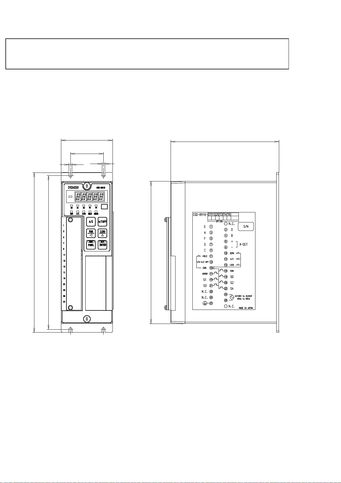
(2) Installation
● When installing the instrument, install as referring to the following
figures and secure the space around the instrument.
Each dimensions of the instrument and required dimensions for the environmental
spaces are as follows:
Outline dimensions
208
200
Front
67
43
4
Side
140.7
4
185
IV
Unit:mm
Page 7

2. Power supply
Warning ● Be sure to check that the power supply is off in connecting each cable.
If the work is done while the power is on, there may have the case that
electric shock to the operator or even may have damage to the
instrument.
● Before supplying the power, check that the indication of power supply
voltage/specifications for
supply should be the same.
If they are not equal, contact us.
If you use the instrument without checking them, it may cause a
damage in the instrument or electric shock to the operator.
the instrument and the power going to
● Earth wire should be grounded securely.
When earth wire is not connected, it may cause a malfunction of the
instrument or electric shock to the operator.
3. Application note
Warning ● Before using a new instrument or exchanging the strain gage applied
transducer for a new one, be sure to make calibration. If calibration
will not be made, the correct measuring results may not be obtained
nor which may cause malfunction in the instrument and there may
exist damage in peripheral equipments.
Besides, even though calibration has been made, there may occur the
similar case when the results are not correct, so make calibration,
again.
Warning ● In case of using the instrument, check that the connections are
executed properly. If not connected properly, the correct measuring
result will not be obtained, nor it may cause malfunctions of the
instrument, damage to the peripheral equipments or even more
serious accidents.
V
Page 8

Warning ● When change of setting is made carelessly on the instrument during
measurement, correct measured results may not be obtained and it
may cause malfunction in the instrument and even have the
possibility of damage in peripheral instruments.
Warning ● Do not shock the instrument such as throwing something on it.
If neglected, it may cause destruction of the parts and damage to the
electrical circuits.
Warning ● Do not push the panel sheet on the instrument with the excessive
strong force nor push it with sharp edge object such as a driver.
If neglected, it may cause a damage to the panel switch and even have
the possibility of damage to resist to environments or operational
performances.
Warning ● Don’t remove the cover of the case of the instrument, nor peel off the
panel sheet nor take the instrument into pieces.
If neglected, it may cause a damage to the case and the panel sheet
and even have the possibility of damage to resist to environments or
operational performances.
● At the time of shipment from the factory, the instrument has been
plated with a clear sheet on the panel sheet for protective purpose.
In case of application, use the instrument after removing the
clearsheet first.
VI
Page 9

History of revision
Date Instruction manual No. Details of revised point
Oct. 2001 DRW. NO.EN294−1143
Jun. 2002 DRW. NO.EN294−1143-A
Sept. 2004 DRW. NO.EN294−1143-B
Apr. 2005 DRW. NO.EN294−1143-C
Aug. 2005 DRW. NO.EN294−1143-D
Version ROM Ver. 1.000 or later
Due to ECN No.FN02−02066
− Change −
Wiring instruction seal affixation is changed right, and the
outline drawing is also changed.
− Additional −
8−2., 13−3. Add F−87
Due to ECN No.FN04−02111
− Change −
7−14. “The backup time is over ten years.” has
changed to “The backup time is about ten years.”
Due to ECN No.FN05−02035
− Addition −
At the warning column in the wiring section, the clause of “
As there is a case which standard wiring color is different,
please confirm the inspection data sheet of the load cell
being used.” is added.
Due to ECN No.FN05−02085
− Correction −
11−8. General specifications
Outline dimensions from “208 mm x 67 mm x 143 mm”
to “208 mm x 67 mm x 140.7 mm”
Due to ECN No.FN10−02013
Jan. 2010 DRW.No.EN294-1143-E
Feb. 2010 DRW.No.EN294-1143-F
May. 2010 DRW.No.EN294-1143-G
Oct. 2010 DRW.No.EN294-1143-H
ROM Ver. 1.800 or later
− Addition −
8−2., 13−3. Add F−84
Due to ECN No.FN10−02013A
− Addition −
8−2. F−84 “Restriction and warning” is added.
Due to ECN No.FN10−02058B
− Addition −
7−3−1. Analog filter
7−7. Detection of stability
7−7−1. Range to detect stability
7−7−2. Time to detect stability
Due to ECN No.FN10−02026B
− Change −
Front cover logo is changed.
Due to ECN No.FN10−02140
− Change −
MInebea logo is changed.
VII
Page 10

Date Instruction manual No. Details of revised point
Due to ECN NO.FN11−02018
− Correction −
Jan. 2011 DRW.No.EN294-1143-I
9−3−4.“DE−9S−N(JAE)”
to “DE−9S−NR by JAE or equivalent.”
Due to ECN No.FN10−02140−D
May 2012 DRW.NO.EN294-1143-J
− Change −
MInebea logo is changed.
Due to ECN No.FN12−02115
ROM Ver. 2.000 or later
− Change −
7−9
4
digit:Optional BCD output”
”10
4
to ”10
digit:Optional output(BCD output, CC−Link load
Aug. 2012 DRW.NO.EN294-1143-K
output, RS−232C load output, RS−422/485 load output)”
− Addition −
7−9 Caution is added.
− Correction −
7−9
”Comparator S1, S2 open collector output”
to ”Comparator S1, S2, S3 and S4 open collector output”
Feb.2018 DRW.NO.EN294-1143-L
Jul.2018 DRW.NO.EN294-1143-M
Due to ECN FN17-02017
・Delete the company name in the cover page.
・Delete the company name in the contents.
Due to ECN FN18-02079
− Change −
10-3 Error display
・Remedy BAT.L/ER−B
SHIFT/ENTER to CHECK/FUNC.
Page 11

INDEX
Forwards Ⅰ....................................................................
Marks and arrangements used in this manual Ⅱ....................................
For safe operation Ⅲ............................................................
1. Installation place Ⅲ.........................................................
2. Power supply Ⅴ............................................................
3. Application note Ⅴ.........................................................
History of revision Ⅶ............................................................
1. General 1.................................................................
1−1. Features 1............................................................
2. Name and function of each point 2..........................................
2−1. Front panel 2.........................................................
3. Installation procedures 4...................................................
3−1. Installation place 4....................................................
3−2. Location where installation is not allowed. 4.............................
3−3. Installation 5.........................................................
4. Connecting method 6......................................................
4−1. Layout of the terminal boards 6.........................................
4−2. Note on connection 7..................................................
4−3. Connection 8..........................................................
4−3−1. Connection with strain gage applied transducers 8..................
4−3−2. Connection with external control inputs 18..........................
4−3−3. Connection with open collector output 19...........................
4−3−4. Connection with the power supply and the earth 20...................
5. Calibration procedures 21...................................................
5−1. Preparations 21........................................................
5−2. Calibration procedures 21...............................................
5−2−1. Calibration method to register the output of strain gage applied transducer
at the time of maximum display after setting the loa d to zero. 22.......
5−2−2. Calibration procedures to register the output of strain gage applied
transducer at the time of zero and the maximum display 28............
5−2−3. Calibration method to register by reading output value
of strain gage applied transducer in the conditions
of zero/actual load application individually 34........................
5−2−4. Zero fine adjustment 41............................................
5−2−5. Span fine adjustment 44...........................................
5−2−6. Calibration procedure to apply registration again for zero point only 47
5−3. Calibration method by communication 51.................................
5−3−1. Calibration method by communication to register the output
of strain gage applied transducer at the time of maximum display
after setting the load to zero. 52....................................
5−3−2. Calibration procedures by communication to register the output of strain gage
applied transducer at the time of zero and the maximum display 57....
5−3−3. Calibration method by communication to register
by reading output value of strain gage applied transducer
in the conditions of zero/actual load application individu 62...........
5−3−4. Zero fine adjustment by communication 68..........................
5−3−5. Span fine adjustment by the communication 71......................
5−3−6. Calibration procedure by the commnunicaitonto apply registration
again for zero point only 74........................................
5−4. Selection of calibration methods on each condition 77
......................
Page 12

5−4−1. In case of executing the calibration on the instrument newly. 77.......
5−4−2. When the calibration is executed again 81...........................
5−5. Setting the prohibition against calibration 81..............................
6. Operation procedure 82.....................................................
6−1.
key 82............................................................
6−1−1. Operations in Measurement mode 82...............................
6−1−2. When operating in the other mode 82...............................
6−2.
key 82............................................................
6−2−1. When operating in the measurement mode 82........................
6−2−2. Operation is made in the other mode 83.............................
key 83............................................................
6−3.
6−3−1. Operation is made in the measurement mode 83......................
6−3−2. Operation in the other mode 83.....................................
6−4.
key 84............................................................
6−4−1. Operation in the measurement mode 84.............................
6−4−2. Operation in the other mode 84.....................................
6−5.
key 84............................................................
6−5−1. Operation in the measurement mode 84.............................
6−6.
key 84............................................................
7. Function and operation 85...................................................
7−1. External control input signal and Open collector output signal 85...........
7−1−1. External control input signal 85....................................
7−1−2. Open collector output signal 86.....................................
7−1−3. Equivalent circuit 87..............................................
7−2. Comparator 87.........................................................
7−2−1. ON/OFF for the Comparator S0, S1, S2, S3 and S4. 87................
7−2−2. Change of set value 88.............................................
7−2−3. Operation on comparator S1, S2, S3 and S4 90.......................
7−2−4. Comparative target for comparator S1, S2, S3 and S4 91..............
7−2−5. Operation of comparator S0 92.....................................
7−2−6. Hysteresis on comparator 95.......................................
7−3. How to use the filter 97.................................................
7−3−1. Analog filter 97...................................................
7−3−2. Digital filter 97...................................................
7−4. Selection of A/D sampling rate 98........................................
7−5. Zero tracking 98........................................................
7−5−1. What is zero tracking? 98..........................................
7−5−2. Setting related with zero tracking 99................................
7−5−3. Cancellation for compensation by zero tracking 100...................
7−6. Stabilized filter 100......................................................
7−6−1. What is the Stabilized filter? 100.....................................
7−6−2. Setting related with the Stabilized filter. 101..........................
7−7. Detection of stability 102.................................................
7−7−1. Range to detect stability 102........................................
7−7−2. Time to detect stability 102.........................................
7−8. Various kinds of functions related with the display 103......................
Page 13

7−8−1. Selection of display rate 103.........................................
7−8−2. Selection of decimal point display position 103........................
7−8−3. Load display range 103.............................................
7−9. Selection the target for HOLD 103.........................................
7−10. Change of bridge power supply voltage 104.................................
7−11. Tare weight cancellation (A/Z) 105........................................
7−12. Zero set 105.............................................................
7−13. Key lock function 105....................................................
7−14. CHECK value 106.......................................................
7−15. Record place of set data etc. 106...........................................
7−16. Prohibition of calibration 106.............................................
7−17. Check mode 107.........................................................
7−17−1. Operating procedure for the check mode 107..........................
7−18. Monitor mode 115.......................................................
8. Function mode 118..........................................................
8−1. Setting method for function mode 118.....................................
8−2. Function of Function data 121............................................
9. Options 130.................................................................
9−1. Analog output 130.......................................................
9−1−1. Relative function 131...............................................
9−1−2. Specification of current output 131..................................
9−1−3. Specification of voltage output 131...................................
9−1−4. Connection of the current output 132................................
9−1−5. Connection with the voltage output 133..............................
9−1−6. Scaling of analog output 134........................................
9−1−7. Fine adjustment 1 on analog output 135..............................
9−1−8. Fine adjustment 2 on analog output 138..............................
9−2. BCD output 141.........................................................
9−2−1. Related function 141...............................................
9−2−2. Specifications for BCD output 141...................................
9−2−3. Pin configurations for the BCD output connector 142..................
9−2−4. Equivalent circuit for input/output 143...............................
9−2−5. Timing chart 144..................................................
9−2−6. Output condition 145...............................................
9−2−7. Selection of output logic for P.C.(Print command), and of its width 146...
9−3. RS−232C interface 147..................................................
9−3−1. Related function 147...............................................
9−3−2. Specifications for interface 147
9−3−3. Procedures of data transfer 148......................................
9−3−4. Pin configurations for connector pin 149.............................
9−3−5. Data format 150...................................................
9−3−6. Communication error process 164...................................
9−4. RS−422/485 interface 165................................................
9−4−1. Related functions 165..............................................
9−4−2. Specifications on interface 166......................................
9−4−3. Procedure of data transmission 166..................................
9−4−4. Pin configurations for connector pin 167.............................
9−4−5. Data format 169...................................................
9−4−6. Communication error process 183...................................
......................................
10. Trouble shooting 184........................................................
Page 14

10−1. Execute trouble shooting 185.............................................
10−2. Optional check 193......................................................
10−3. Error display 201........................................................
11. Specifications 203...........................................................
11−1. Specifications for analog section 203.......................................
11−2. Specifications for digital section 203.......................................
11−3. Front panel sheet key function 204........................................
11−4. External control function 204.............................................
11−5. Comparator function 204.................................................
11−6. Open collector output signal 205..........................................
11−7. Various kinds of functions 205............................................
11−8. General specifications 205................................................
11−9. Standard specifications at the shipment 206................................
11−10. Accessories 206..........................................................
11−11. Options 206.............................................................
11−11−1. Analog output 206.................................................
11−11−2. BCD output 207...................................................
11−11−3. RS−232C interface 207.............................................
11−11−4. RS−422/485 interface 208..........................................
11−12. Outline dimensions 208..................................................
12. Warranty 209................................................................
12−
1. Warranty 209...........................................................
12−2. Repair 209..............................................................
13. Appendix 210................................................................
13−1. Replacement of fuse 210..................................................
13−2. Character’s pattern for display 213........................................
13−3. Setting table for functions 214............................................
Page 15

1. General
The instrument is a digital indicator for the application of strain gage applied transducer.
1−1. Features
Main features for CSD−891B are as follows :
(1) Compact size
The size of 208 mm×67 mm×143 mm is suitable for storage in the board.
(2) Non−linearity
Display 0.01 %F.S.
(3) High speed sampling
High speed sampling as 200 times/s
1
Page 16

2. Name and function of each point
2−1. Front panel
①
②
③
⑩
⑫
④
⑤
⑥
⑦
⑧
⑨
⑪
1
Load display section
The load data is shown in the Measurement mode, and status or set value is shown in various
kinds of Calibration mode and Setting mode.
2
Judgement display
Compared results by comparator function can be displayed.
3
Status display
RUN Lights up in the measurement mode.
A/Z Lights up in executing the tare weight cancellation (A/Z ON).
Lights off after clearing the tare weight cancellation (A/Z OFF).
LOCK Lights up when the input between the HOLD and COM. at the external control is
shorted. During light on, any key operation is prohibited.
HOLD Lights up when the input between the HOLD and COM. at the external control is
shorted.
CHECK Lights up when the CHECK is turned on by pressing the
key.
the
2
key together with
Page 17

4
key
Using for executing the tare weight cancellation(A/Z ON).
5
key
Using for clearing the tare weight cancellation(A/Z OFF).
6
key
Using for calling the change mode of the set value, or carry up the numeric in the various
setting.
7
key
Using for executing the zero set(one touched zero adjustment), or the numeric increment in
the various setting.
8
key
Using for shifting to the function mode.
Also, using for turning on/off of the check value by pressing the
key together with the
key.
9
key
Using for registering the set values at the time of various settings.
Also, using for turning on/off the check value by pressing
10
Terminals
Connects with the external control input, the open collector output, the strain gage applied
transducers, such as load cell, the analog output, the AC power supply, and ground.
11
Optional products attaching portion
One option either of BCD−OUT, CC−LINK, RS−232C, or RS−422/485 is installed.
The cover is installed when there is no optional products.
12
Position where unit seal is pasted
Please put the unit seal of the attachment if necessary.
key together with the key.
3
Page 18

3. Installation procedures
3−1. Installation place
● Use the instrument where the temperature/humidity specifies within
the range as follows:
Environmental temperature :−10 ℃ to 50 ℃
Environmental humidity :85 %RH or less(Non condensing.)
3−2. Location where installation is not allowed.
Warning ● Don’t locate the instrument on the places such as follows:
It may cause an unexpected faulty in the instrument.
D Do not expose the instrument in direct sunlight and/or high temperature area.
D Do not use the instrument in a high humid area.
D Do not install the instrument where there is high mechanical vibrations and shock.
D Do not use the instrument where there are excess of dusts and fine particles.
D Do not install the instrument where there include any corrosive gas or any salty
atmosphere.
D Do not install the instrument where there is rapid change of temperature and humidity.
D Do not install the instrument near the devices that are magnetized or generate an
electromagnetic field.
D Do not install the instrument where there may suffer radioactivity or radioactive rays.
D Avoid the location where chemical reaction may take place such as in a laboratory, or like
that.
4
Page 19
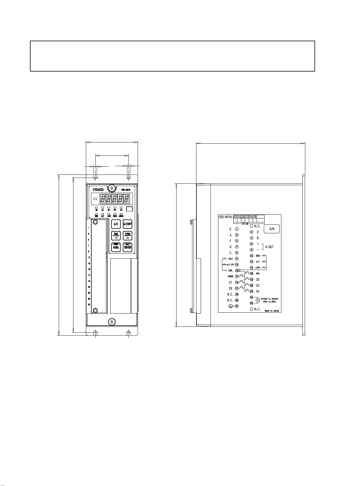
3−3. Installation
● When installing the instrument, install as the following figures and
secure the space around the instrument.
Each dimensions of the instrument and required dimensions for the environmental spaces are as
follows:
Outline dimensions
208
200
Front
67
43
4
Side
140.7
4
185
Unit:mm
5
Page 20
4. Connecting method
Strain
gage
t
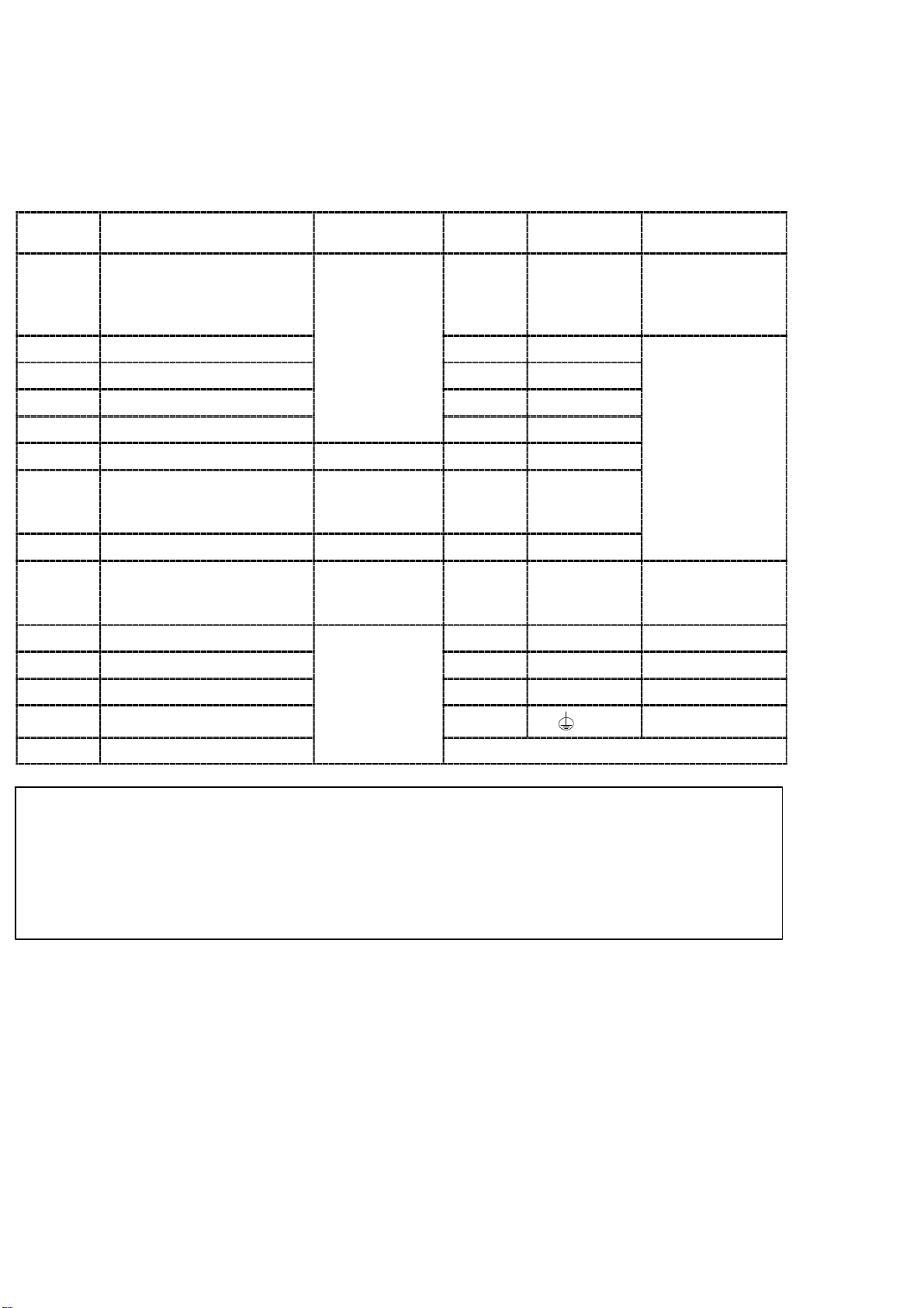
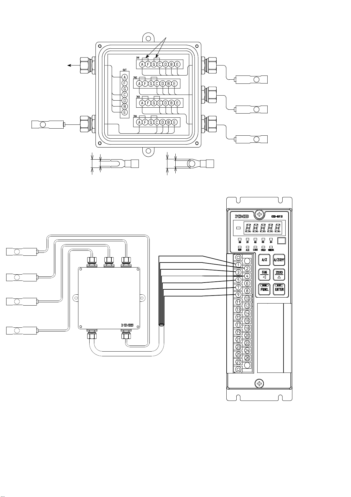
4−1. Layout of the terminal boards
There is the terminal boards, which has 27 points of terminals.
Layout of terminal boards are shown in the following figure.:
Terminal
No.
1 E(Shield)
2 D(Amplifier input +)
3 A(Bridge power supply +)
4 B(Amplifier input −) 18 SO
5 F(Sensing +) 19 S1 Open collector
6 A−OUT + Analog output 20 S2
7 G(Sensing −)
8 A−OUT − Analog output 22 S4
9 C(Bridge power supply −)
10 ZERO 24 SOURCE AC power supply
11 HOLD 25 N.C.
12 A/Z
13 A/Z OFF
Descriptions Applications
applied
transducer
Strain gage
applied
transducer
Strain gage
applied
transducer
External
controloutpu
Terminal
No.
15 COM.
16 RUN
17 ERROR
21 S3
23 N.C.
26 SOURCE AC power supply
27 Ground
Descriptions Applications
Common for
external control
input and open
collector output
output
14 LOCK
● The COM.(Terminal No.15) is common for the external control input
(Terminal No.10〜14) and the open collector output(Terminal No.16
〜22).
● Don’t connect with N.C. terminals(Terminal No.23 and 25).
6
Page 21
4−2. Note on connection
Warning ● In case of connection with the instrument, keep strictly to the
following items. If neglected, it may cause an unexpected failure or a
damage to the instrument.
D Be sure to set the power supply to OFF, when the connection will be made.
D Since the terminal boards at front of the instrument is made of resin, take care not to drop
it down or not to apply strong impact.
D Recommended torque to tighten the terminal screws for terminal board should be as
follows.
Torque to tighten the terminal screws
Terminals 0.6 N・m
D The suitable crimp type terminal lugs for the terminal board are as follows:
Width of crimp type terminal lugs Suitable crimp type terminal lugs
Terminals 6.2 mm or less 1.25−3orY−type 1.25−3.5
D Connecting cable with the instrument should be away from the noise source such as power
supply line and/or I/O line for control and so on as far as possible.
D Conduit wiring should be the type of exclusive one, and avoid using with another line
together.
D All of the connections should be executed securely by referring to the Instruction manual
for the instrument.
7
Page 22

4−3. Connection
4−3−1. Connection with strain gage applied transducers
The instrument can connect with strain gage applied transducers, such as load cell, pressure
transducer and so on. Here, we will describe the example of connections with load cell, so the
connection with another type of strain gage applied transducers shall be proceeded in the same
way.
※1 When tension is applied with the application of tension type or
universal(compression/tension) type of load cell, and display of “+”
direction is required, connect “Green” with Terminal No.4 and
“Blue” with Terminal No.2 individually. As there is a case which
standard wiring color is different, please confirm the inspection data
sheet of the load cell being used.
※2 When the length of CAB−502 is more than 30 m totally, there may
have the case that the accuracy is out of warranty because the
resistance of cable makes the input voltage of the instrument
decreased.
※3 When the length of CAB−501 is more than 100 m totally, there may
have the case that the accuracy is out of warranty because the
resistance of cable makes the remote sensing function not worked
fully.
8
Page 23

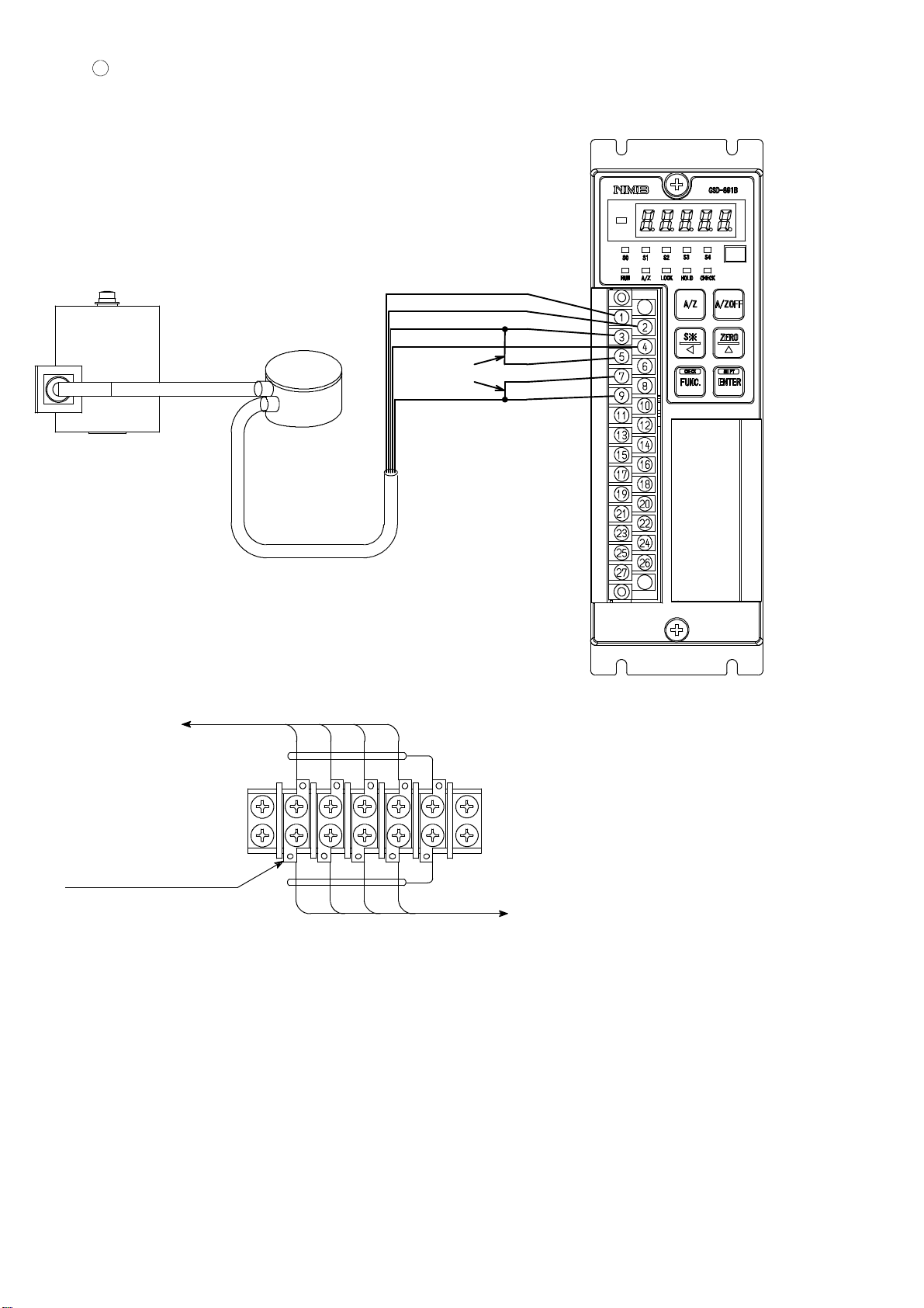
1
Connection with 1 piece of load cell and CSD−891B
Shield
3m
Green ※1
Red
Blue ※1
Attached
short bar
White
※1 When tension is applied with the application of tension type or
universal(compression/tension) type of load cell, and display of “+”
direction is required, connect “Green” with Terminal No.4 and
“Blue” with Terminal No.2 individually. As there is a case which
standard wiring color is different, please confirm the inspection data
sheet of the load cell being used.
※2 When the length of CAB−502 is more than 30 m totally, there may
have the case that the accuracy is out of warranty because the
resistance of cable makes the input voltage of the instrument
decreased.
※3 When the length of CAB−501 is more than 100 m totally, there may
have the case that the accuracy is out of warranty because the
resistance of cable makes the remote sensing function not worked
fully.
9
Page 24
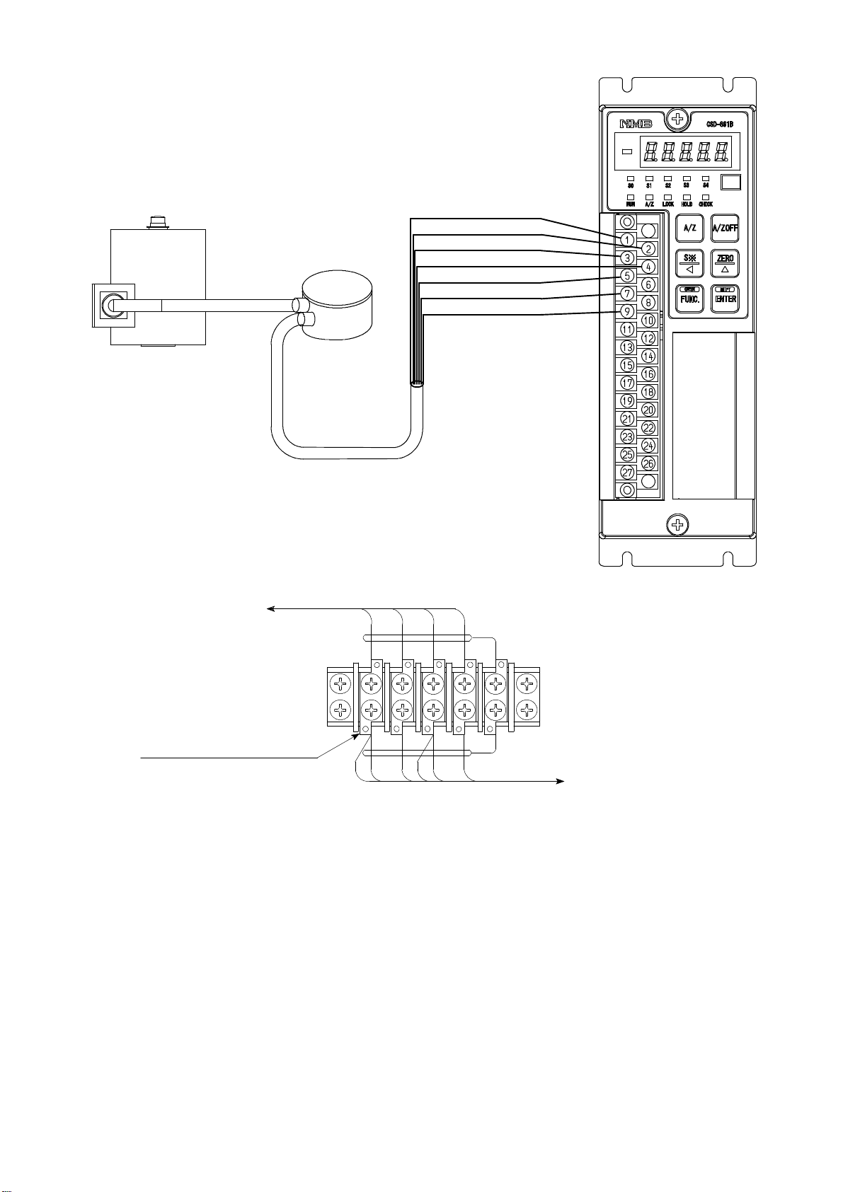
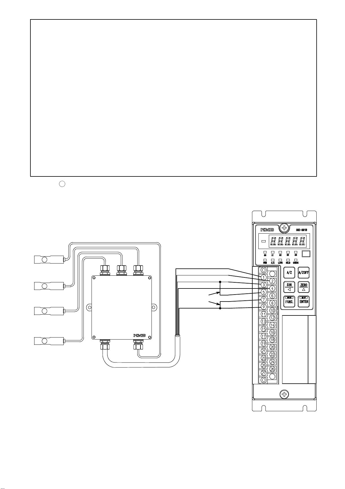
2
Connection with 1 piece of load cell and a junction box for extension use(B−304) and
CSD−891B
i) When CAB−502(4−cores cable)is used.
Shield
Green ※1
Red
Blue ※1
Attached
short bar
White
3m
Junction box
B−304
CAB−502
※2 (The length of CAB−502 is within 30 m totally.)
Internal wiring diagram of B−304
to load cell
RED WHTBLU
GRN YEL(Shield)
Terminal pitch 9.5 mm
RED WHTBLU
GRN
Suitable crimp type terminal lugs
:1.25−4or2−4
YEL(Shield)
to CSD−891B
10
Page 25
ii) When CAB−501(6−cores cable) is used
Junction box
3m
B−304
CAB−501
Shield
Green ※1
Red
Blue ※1
Orange
Black
White
※2 (The length of CAB−501 is within 100 m totally.)
Internal wiring diagram of B−304
To Load cell
BLU
Terminal Pitch 9.5 mm
ORN
RED WHT
BLU
RED
BLK
WHT
GRN
GRN
YEL(Shield)
Suitable crimp−type
terminal lugs:
1.25−4or2−4
YEL(Shield)
To CSD−891B
11
Page 26
※1 When tension is applied with the application of tension type or
universal(compression/tension) type of load cell, and display of “+”
direction is required, connect “Green” with Terminal No.4 and
“Blue” with Terminal No.2 individually. As there is a case which
standard wiring color is different, please confirm the inspection data
sheet of the load cell being used.
※2 When the length of CAB−502 is more than 30 m totally, there may
have the case that the accuracy is out of warranty because the
resistance of cable makes the input voltage of the instrument
decreased.
※3 When the length of CAB−501 is more than 100 m totally, there may
have the case that the accuracy is out of warranty because the
resistance of cable makes the remote sensing function not worked
fully.
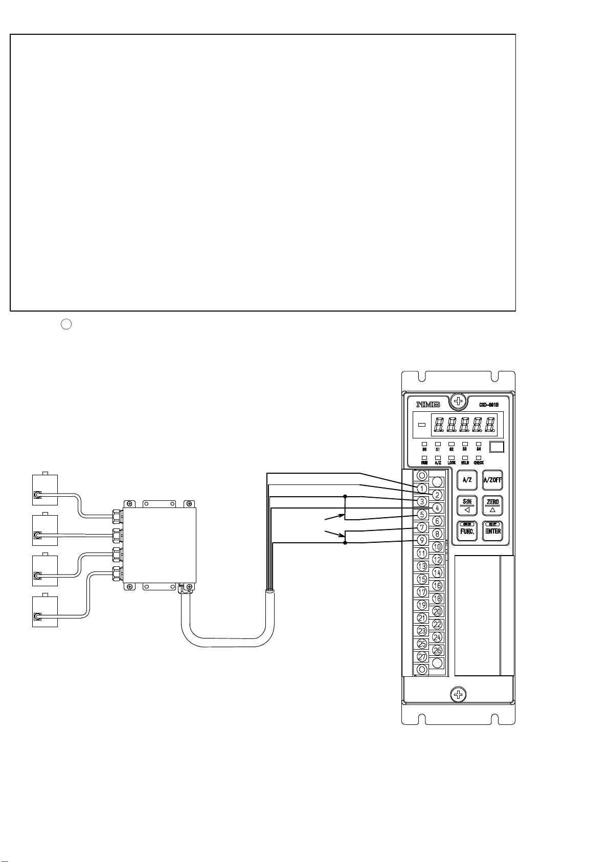
3
Connection with 2 to 4 points of load cells and Summing type junction box(B−307) and
CSD−891B
i) When CAB−502(4−cores cable) is used.
Junction box
B−307
CAB−502
Shield
Green ※1
Red
Blue ※1
Attached
short bar
White
※2 (The length of CAB−502 is within 30 m totally.)
12
Page 27
Internal wiring diagram of B−307
WHT
RED
GRN
BLU
YEL(Shield)
WHT
RED
GRN
BLU
YEL(Shield)
WHT
RED
GRN
BLU
YEL(Shield)
WHT
RED
GRN
BLU
YEL(Shield)
1W
1R
1G
1B
1Y
2W
2R
2G
2B
2Y
3W
3R
3G
3B
3Y
4W
4R
4G
4B
4Y
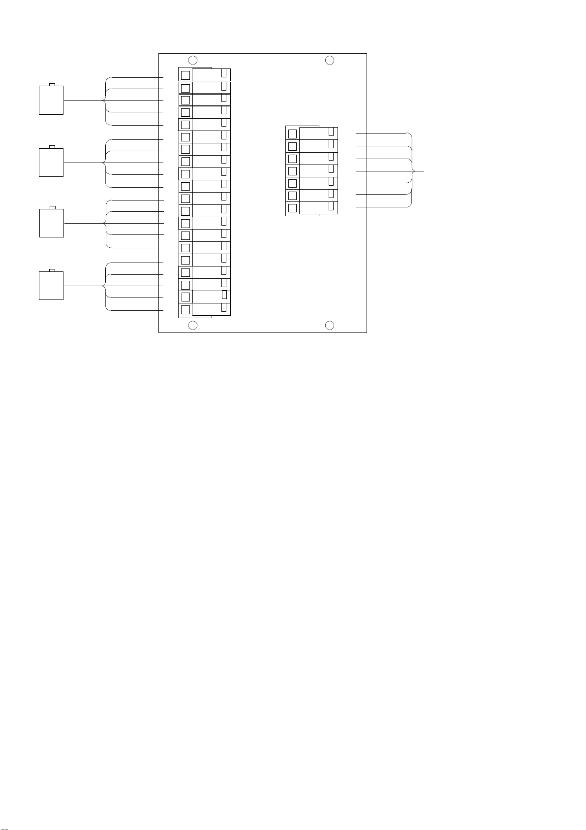
ii) When CAB−501(6−cores cable) is used.
RD
OR
BK
WH
GN
BL
YE
RED
WHT
GRN
BLU
YEL(Shield)
to CSD−891B
Shield
Green ※1
Red
Junction box
Blue ※1
Orange
Black
White
B−307
CAB−501
※2 (The length of CAB−501 is within 100 m totally.)
13
Page 28
Internal wiring diagram of B−307
WHT
RED
GRN
BLU
YEL(SHIELD)
WHT
RED
GRN
BLU
YEL(SHIELD)
WHT
RED
GRN
BLU
YEL(SHIELD)
WHT
RED
GRN
BLU
YEL(SHIELD)
1W
1R
1G
1B
1Y
2W
2R
2G
2B
2Y
3W
3R
3G
3B
3Y
4W
4R
4G
4B
4Y
RD
OR
BK
WH
GN
BL
YE
RED
ORG
BLK
WHT
GRN
BLU
YEL(SHIELD)
To CSD−891B
14
Page 29
※1 When tension is applied with the application of tension type or
universal(compression/tension) type of load cell, and display of “+”
direction is required, connect “Green” with Terminal No.4 and
“Blue” with Terminal No.2 individually. As there is a case which
standard wiring color is different, please confirm the inspection data
sheet of the load cell being used.
※2 When the length of CAB−502 is more than 30 m totally, there may
have the case that the accuracy is out of warranty because the
resistance of cable makes the input voltage of the instrument
decreased.
※3 When the length of CAB−501 is more than 100 m totally, there may
have the case that the accuracy is out of warranty because the
resistance of cable makes the remote sensing function not worked
fully.
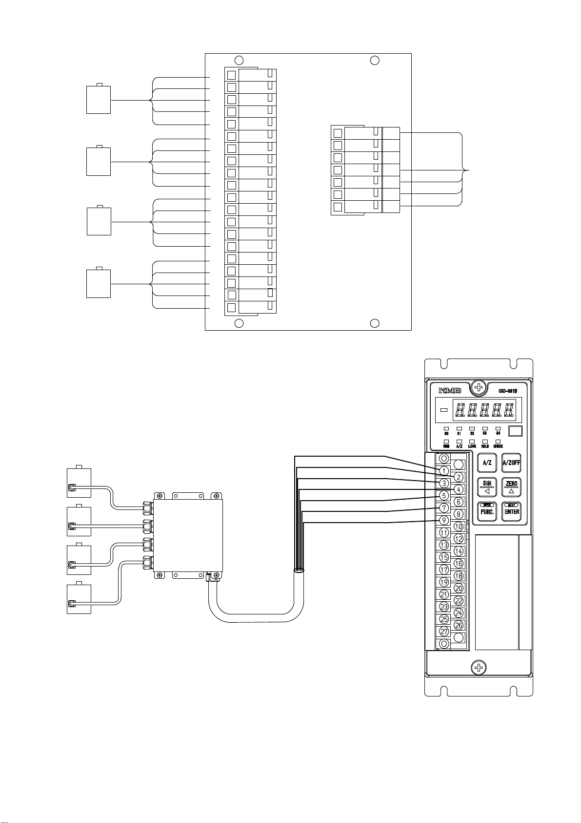
4
Connection with 2 to 4 points of load cells and Summing type junction box (SB−310) and
CSD−891B.
i) When CAB−502(4−cores cable) is used.
Junction box
SB−310
CAB−502
Shield
Green ※1
Red
Blue ※1
Attached
short bar
White
※2 (The length of CAB−502 is within 30 m totally.)
15
Page 30
Internal wiring diagram of SB−310
Output port
to CSD−891B
RD
Short bar
Input port No.1
YERD WH BLGR
WH
GR
Input port
No.4
BL
YE
Suitable crimp type
A
terminal lugs:
B
・Y type ・Round type
ii) When CAB−501(6−cores cable) is used.
Junction box
SB−310
or
YERD WH BLGR
YERD WH BLGR
φB
φA
Shield
Green ※1
Red
Blue ※1
Orange
Black
White
Input port No.2
YERD WH BLGR
Input port No.3
A:3.2 mm or less
B:7 mm or less
CAB−501
※2 (The length of CAB−501 is within 100 m totally.)
16
Page 31

Internal wiring diagram of SB−310
Output
Point
To CSD−891B
Input
Point 4
Short bar
Input
Point 1
GN BL
WH
OR BK
RD
OR
BK
WH
GN
BL
YE
RD
RD
OR BK
WH GN
RD
OR BK
YE
BL
YE
Input
Point 2
BL
WH
YE
GN
Input
RD
OR
BK
WH
GN BL
YE
Point 3
Suitable solderless
terminal
B
A
・Y type
or
φB
φA
・Round type
A: 3.2 mm or less
B: 7 mm or less
17
Page 32

4−3−2. Connection with external control inputs
Connections with external control input “ZERO”, “A/Z”, “A/Z OFF”, “HOLD” and “LOCK”
should be made according to the below figures by using a contact or an open collector between
the each terminal and terminal No. 15 at “COM.”
Refer to the paragraph 7−1 for the function of each input.
or
Shield
Warning ● Connections with external control outputs should be made securely
according to the figures. If neglected, it may cause an unexpected
failure and/or malfunction to the instrument.
● For the connections with external control inputs, be sure to apply
shielded cable, and the shielded cable should be connected with
terminal(Terminal No.27)
If not connected, it may cause malfunction due to the effects from
external noises and so on.
18
Page 33

4−3−3. Connection with open collector output
Connections with open collector outputs “RUN”, “ERROR”, “S0”, “S1”, “S2”, “S3” and “S4”
and the external load should be made by using each terminal and terminal No. 15 at “COM.”.
At the same time, take care that the load should not exceed the rated load of open collector
output.
The rated load of open collector V
load
Surge preventive element
(Please prepare the external power
supply for load separately.)
+
−
=DC30 V, IC=DC30 mA MAX.
CE
Shield
Warning ● Connections with the open collector outputs should be made securely
according to the figures and also within the rated capacity of the open
collector. If neglected, it may cause an unexpected failure and/or
malfunction to the instrument.
● For the protection in the open collector of this instrument, connect
the surge preventive element that satisfies the characteristics of
external load to connect. If neglected, it may cause unexpected failure
and/or malfunction due to the effects from damage/melt down of the
open collector output of this instrument.
19
Page 34

● For the connections with contact outputs, be sure to apply shielded
cable, and the shielded cable should be connected with GND terminal
(Terminal No.27) of the instrument. If not connected, it may cause
malfunction due to the effects from external noises and so on.
4−3−4. Connection with the power supply and the earth
Connections with the power supply and the earth should be made as the following figure.
Grounding should be the D class with single earth.
Power supply voltage AC100 V to AC240 V
(Allowable variable range:AC85 V to AC264 V)
Frequency for power supply 50/60 Hz
Power consumption Approx.19 VA at maximum. (at AC100 V)
AC100 V to AC240 V
(Allowable variable range
:AC85 V to AC264 V)
〜
D class with
single earth
Warning ● Connections with the power supply and the earth should be made
securely according to the figures and also within the rated capacity of
the instrument. If neglected, it may cause an unexpected error.
● Grounding should be the D class with single earth.
If neglected, it may cause an unexpected malfunction due to the
effects of noise from other equipments.
20
Page 35

5. Calibration procedures
Warning ● Before using the new instrument or after exchanging the strain gage
applied transducer with a new one, be sure to make calibration.
If calibration is not made, correct measured results may not be
obtained, or it may cause malfunction to the instrument and it may
damage the peripheral equipment.
Moreover, even if calibration has made, there may occur the similar
case as above when the result is not correct. So make precise
calibration again.
● The calibration for the instrument and “Display value at the time of
minimum analog output”(F−21) and “Display value at the time of
maximum analog output” (F−22) are not interlocked. In due course,
make check on the setting for F−21 and F−22 securely.
If neglected, correct outputs may not be obtained, or it may cause
malfunction to the instrument and it may damage the peripheral
equipment.
5−1. Preparations
According to the Chapter 4. Connecting method, connect the instrument and the strain gage
applied transducer properly, then supply the power.
5−2. Calibration procedures
Load calibration procedures for the instrument are as follows:
1
Calibration method to register the output (conversion with mV/V) of strain gage applied
transducer at the time of maximum display (weighing capacity) after setting the load to zero
(Initial load condition with tare weight).
2
Calibration method (Automatic calibration for Zero and Span) to register the output of strain
gage applied transducer (conversion with mV/V) at the time of zero load(Initial load
application with tare) at the optional load condition, and also to register the output
(conversion with mV/V) of strain gage applied transducer at the time of maximum display
(weighing capacity).
3
Calibration method (Actual load calibration) to register by the reading output of strain gage
applied transducer, when setting in the condition of zero load applied (Initial load application
with tare) and in the condition of actual load applied individually.
4
Fine adjustment on Zero
5
Fine adjustment on Span
6
Calibration procedures to apply registration again for zero point only(Tare weight
cancellation).
21
Page 36

● The accuracy of calibration obtained from ① and ② is 1/1 000 or so.
If more than the accuracy 1/1 000 is required, make calibration of ③
type.
In the following paragraphs, we will describe each calibration procedure by showing the
examples with load cell applied.
5−2−1. Calibration method to register the output of strain gage applied transducer at the time
of maximum display after setting the load to zero.
Warning ● Before using a new instrument or exchanging the strain gage applied
transducer for a new one, be sure to make calibration.
If calibration shall not be made, correct measured results may not be
obtained nor it may cause malfunction in the instrument and there
may exist damage to the peripheral equipment.
Besides, even though the calibration has been made, there may occur
the similar case when the result is not correct, so make calibration
again.
● During the calibration is executing, be sure to set Tare weight
cancellation clear, and to make cancellation (Execution of F−98) for
compensated data on zero set and set the OFF position of Zero
tracking(Setting “00000” on F−08 and F−09), and also set the OFF
position o Peak.
● During calibration procedures, press the key in case of
interrupting the calibration is required. The calibration data will be
kept as they are before entering the calibration and then returns to
the Measurement mode.
● Every time the
the display will change as the following arrow marks. Furthermore,
every time the
direction of the following arrow marks. However, “VCAL” and “VADJ”
key is pressed with the load display of “FUNC”,
is pressed, the display will change as the reverse
appears only when the optional analog output is attached.
“FUNC”→“CCAL”→“ACAL”→“LCAL”→“ZERO”→“SPAN”→
“TARE”→“CHEK”→“MONT”→“VCAL”→“VADJ”→“FUNC”→
“CCAL”→・・・・・ (Hereinafter, it will repeat.)
22
Page 37

Procedures
Press the key for about one second
The load display shows “FUNC”.
1
Press the key twice.
It makes the load display proceed as “CCAL”.
2
Press the key.
“CCAL” mode can be entered, then the load
display shows “SCAL”.
3
23
Page 38

Procedures
Press the key.
The load display shows “D−01” and it flashes on
and off.
When the calibration has completed already, the
set value of minimum scale registered at that
time is displayed.
Set the minimum scale with the right keys.
Setting value for the minimum scale are 4 (four)
4
as follows:
1, 2, 5, 10
Press the key.
The load display will show “DISP”.
key :Set value inclement key
5
24
Page 39

Procedures
Press the key.
The load display shows ”2000”, and the digit of
minimum display flashes on and off.
When the calibration has completed already, the
registered value of maximum display at that time
is displayed.
By the setting of minimum scale, the digit
of minimum display that flashes on and off
are as follows:
The minimum scale 1, 2, 5 100digit
The minimum scale 10 10
Set the maximum display value with the right
keys. The setting range for the maximum display
value is (the minimum scale×100)〜99 990.
In order to make effective use of the performance,
6
set within the following ranges.
When setting is made over the range as below,
there may have a possibility of unstable display
and so on.
Setting range for the
maximum display value
The minimum scale
1
digit
key :Set value carry key
key :Set value inclement key
key :Set value initialization key
100〜10 000
200〜20 000
500〜50 000
1 000〜99 990
By pressing the key continuously,
increment can be provided continuously.
Press the key.
The load display shows ”S MV”.
7
1
2
5
10
25
Page 40

Procedures
Press the key.
The load display will show “0.3000”, and the
digit of 10
In case that calibration has completed already,
the registered output value of load cell at that
time is displayed.
Set the value with the right keys, which is
subtracted the output value of load cell at the
time of initial load application from the output
value of load cell corresponding to the maximum
display value set in the step 6.
0
flashes on and off.
Though the number of digits has not
prepared in the “Inspection data” for load
8
cell so many as shown in the right figure,
extra digits are necessary for the
compensation with the standard point at
internal of the instrument.
In case of actual setting, insert “0”, into the
extra digits.
As for the value for extra digit, when tare
compensation and fine adjustment on load
are applied, it will be rewritten as a
compensated value automatically.
Setting range for the output of load cell is
from 0.200 0 mV/V to 3.100 0 mV/V.
key :Set value carry key
key :Set value inclement key
key :Set value initialization key
By pressing the key continuously,
increment can be provided continuously.
Press the key.
The load display showS “ZERO”.
Here, set the instrument with initial load
application.
9
26
Page 41

Procedures
Press the key.
The load display shows “ZERO” with lighting
display on and off, then zero adjustment can be
started.
Warning :At the same time, take care not
to apply load variation due to vibration and
10
so on. When load variation is applied, there
will be possibilities that zero point is
unstable, and precise reading of zero will
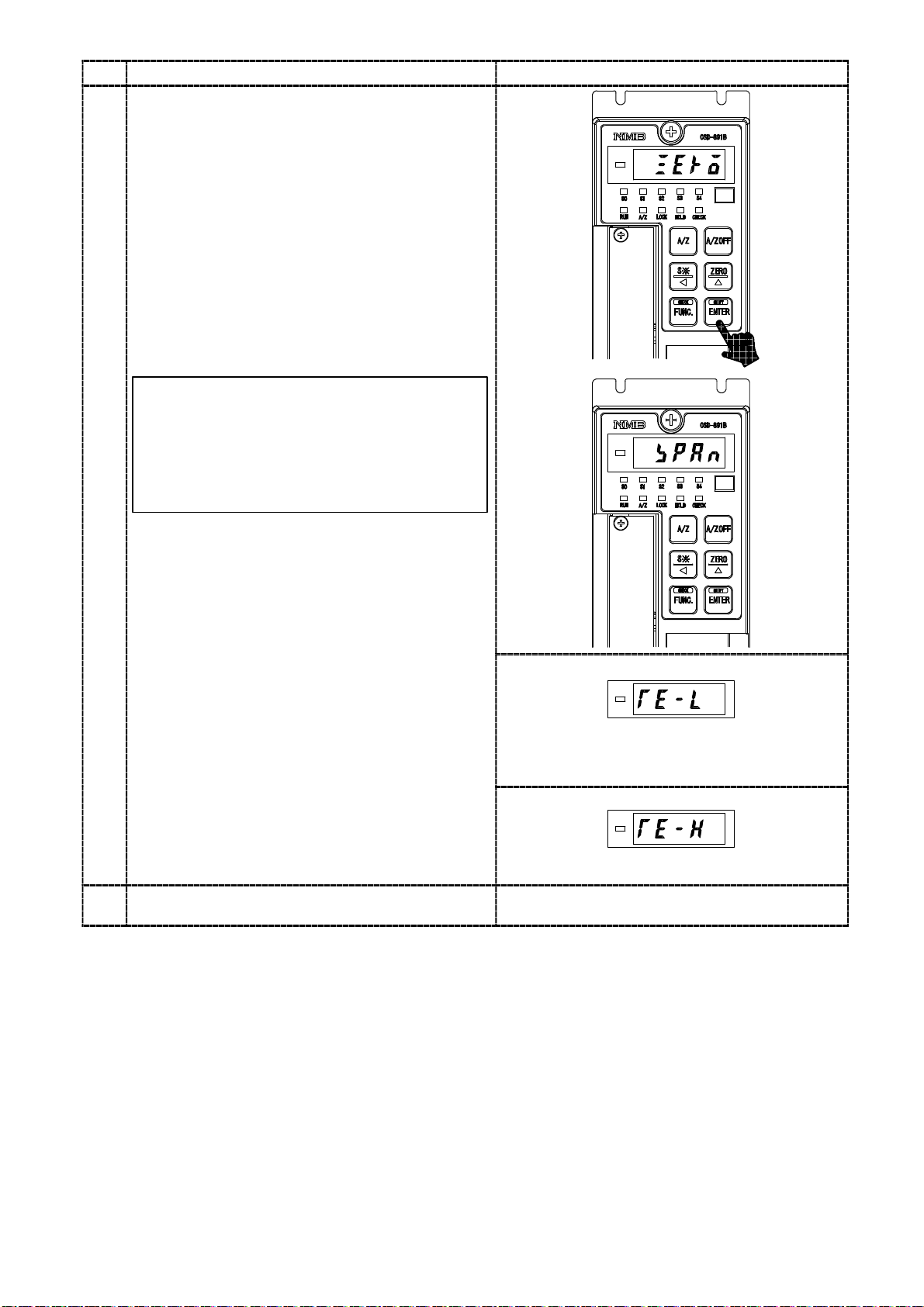
not be obtained.
11
After completed, the load display becomes
“END”.
However, when the initial load is not entered
within the range from −2.5 mV/V to 2.5 mV/V,
the error code shown in the right figure will
show for about 2 seconds, then load display will
show “ZERO” and return to step 9.
TE−L :Zero point −OVER
TE−H :Zero point +OVER
Press the key.
After “CCAL” mode is over, the load display
shows the present load.
Error code
Error code
27
Page 42

5−2−2. Calibration procedures to register the output of strain gage applied transducer at the
time of zero and the maximum display
(1) Procedure by key operation
Warning ● Before using a new instrument or exchanging the strain gage applied
transducer for a new one, be sure to make calibration.
If calibration shall not be made, correct measured results may not be
obtained nor may cause malfunction in the instrument and there may
exist damage in peripheral equipments.
Besides, even though calibration has been made, there may occur the
similar case when the result is not correct, so make calibration again.
● During the calibration is executing, be sure to set Tare weight
cancellation clear, and to make cancellation (Execution of F−98) for
compensated data on zero set and set the OFF position of Zero
tracking(Setting “00000” on F−08 and F−09).
● During calibration procedures, press the key in case of
interrupting the calibration is required. The calibration data is kept as
they are before entering the calibration and then returns to the
Measurement mode.
● Every time the key is pressed with the load display of “FUNC”,
the display will change as the following arrow marks. Furthermore,
every time the
direction of the following arrow marks. However, “VCAL” and “VADJ”
appears only when the optional analog output is attached.
“FUNC”→“CCAL”→“ACAL”→“LCAL”→“ZERO”→“SPAN”→
“TARE”→“CHEK”→“MONT”→“VCAL”→“VADJ”→“FUNC”→
“CCAL”→・・・・・ (Hereinafter, it will repeat.)
is pressed, the display will change as the reverse
28
Page 43

Procedures
Press the key for about one second
The load display shows “FUNC”.
1
Press the key twice.
It makes the load display proceed as
“FUNC”→“CCAL”→“ACAL”.
2
Press the key.
“ACAL” mode can be entered, then the load
display shows “SCAL”.
3
29
Page 44

Procedures
Press the key.
The load display shows “D−01” and it flashes on
and off.
When the calibration has completed already, the
set value of minimum scale which has registered
at that time is displayed.
Set the minimum scale with the right keys.
Setting value for the minimum scale are 4 (four)
4
as follows:
1, 2, 5, 10
Press the key.
The load display shows “DISP”.
key :Set value inclement key
5
30
Page 45

Procedures
Press the key.
The load display shows “2000” and the minimum
display digit flashes on and off.
When the calibration has completed already, the
maximum display value which has registered at
that time is displayed.
By the setting of minimum scale, the digit
of minimum display that flashes on and off
are as follows:
The minimum scale 1,2,5 100digit
The minimum scale 10 10
Set the maximum display value with the right
keys. The setting range for the maximum display
value is (the minimum scale×100)〜99 990.
6
In order to make effective use of the performance,
set within the following ranges.
When setting is made over the range as below,
there may have a possibility of unstable display
and so on.
Setting range for the
maximum display value
100〜10 000
200〜20 000
500〜50 000
The minimum scale
1
2
5
1
digit
key :Set value carry key
key :Set value inclement key
key :Set value initialization key
1 000〜99 990
By pressing the key continuously,
increment can be provided continuously.
Press the key.
The load display will show “Z MV”.
7
10
31
Page 46

Procedures
8
Press the key.
The load display shows ”0.0000”, and the digit
0
will flash on and off. In case that
of 10
calibration has completed already, the registered
output value of load cell at that time is
displayed. Set the output value for load cell with
the initial load application with the right keys.
Though the number of digits has not
prepared in the ”Inspection data” for load
cell so many as shown in the right figure,
extra digits are necessary for the
compensation withthestandardpoint at
internal of the instrument.
In case of actual setting, insert “0”, into the
extra digits.
As for the value for extra digit, when tare
compensation and fine adjustment on load
are applied, it is rewritten as a compensated
value automatically.
Setting range for the output of load cell is
from −2.500 0 mV/V to 2.500 0 mV/V.
key :Set value carry key
key :Set value inclement key
key :Set value initialization key
By pressing the key continuously,
increment can be provided continuously.
Press the key.
The load display shows “S MV”.
9
32
Page 47

Procedures
Press the key.
The load display shows “0.300 0” and the digit at
0
will flash on and off. In case that calibration
10
has completed already, the registered output
value of load cell at that time is displayed.
Set the output value for load cell corresponding
to the maximum display value with the initial
load application with the right keys.
The set value to be set here should be
0.2 mV/V or more than the set value in the
step 8. Though the number of digits has not
10
prepared in the Inspection data for load cell
as many as the digits in the right figure,
extra digits are necessary for the
compensation for the internal standard
point of the instrument. In case of actual
setting, insert “0” into the extra digits.
As for the value of extra digits, when tare
compensation and fine adjustment on load
are applied, it is written as a compensated
value automatically.
key :Set value carry key
key :Set value inclement key
key :Set value initialization key
11
By pressing the key continuously,
increment can be provided continuously.
Press the key.
The load display shows the “END”.
Press the key.
After “ACAL” mode is over, the load display
shows the present load.
12
33
Page 48

5−2−3. Calibration method to register by reading output value of strain gage applied
transducer in the conditions of zero/actual load application individually.
(1) Procedures by the key operation
Warning ● Before using a new instrument or exchanging the strain gage applied
transducer for a new one, be sure to make calibration.
If calibration shall not be made, correct measured results may not be
obtained nor may cause malfunction in the instrument and there may
exist damage in peripheral equipments.
Besides, even though calibration has been made, there may occur the
similar case when the result is not correct, so make calibration again.
● During the calibration is executing, be sure to set Tare weight
cancellation clear, and to make cancellation (Execution of F−98) for
compensated data on zero set and set the OFF position of Zero
tracking(Setting “00000” on F−08 and F−09).
● During calibration procedures, press the key in case of
interrupting the calibration is required. The calibration data is kept as
they are before entering the calibration and then returns to the
Measurement mode.
● Every time the key is pressed with the load display of “FUNC”,
the display will change as the following arrow marks. Furthermore,
every time the
direction of the following arrow marks. However, “VCAL” and “VADJ”
appears only when the optional analog output is attached.
“FUNC”→“CCAL”→“ACAL”→“LCAL”→“ZERO”→“SPAN”→
“TARE”→“CHEK”→“MONT”→“VCAL”→“VADJ”→“FUNC”→
“CCAL”→・・・・・ (Hereinafter, it will repeat.)
is pressed, the display will change as the reverse
34
Page 49

Procedures
Press the key for about one second.
The load display shows “FUNC”.
1
Press the key three times.
It makes the load display proceed as
“FUNC”→“CCAL”→“ACAL”→“LCAL”.
2
Press the key.
“LCAL” mode can be entered, then the load
display shows “SCAL”.
3
35
Page 50

Procedures
Press the key.
The load display shows “D−01” and it flashes on
and off.
When the calibration has completed already, the
set value of minimum scale registered at that
time is displayed.
Set the minimum scale with the right keys.
Setting value for the minimum scale are 4 (four)
4
as follows:
1, 2, 5, 10
Press the key.
The load display shows “DISP”.
key :Set value inclement key
5
36
Page 51

Procedures
Press the key.
The load display shows “2000” and the minimum
display digit flashes on and off.
When the calibration has completed already, the
maximum display value which has registered at
that time is displayed.
By the setting of minimum scale, the digit
of minimum display that flashes on and off
will be as follows:
The minimum scale 1,2,5 10
The minimum scale 10 10
Set the maximum display value with the right
keys. Setting range for the maximum display
value is (the minimum scale×100)〜99 990.
In order to make effective use of the performance,
6
set within the following ranges.
When setting is made over the range as below,
there may have a possibility of unstable display
and so on.
Setting range for the
maximum display value
The minimum scale
0
1
digit
digit
key :Set value carry key
key :Set value inclement key
key :Set value initialization key
100〜10 000
200〜20 000
500〜50 000
1 000〜99 990
By pressing the key continuously,
increment can be provided continuously.
Press the key.
The load display shows “LOAD”.
7
1
2
5
10
37
Page 52

Procedures
Theloadval
the
loadcellshould
b
y
t
y
Press the key.
The load display shows “2000”, and the digit of
0
flashes on and off.
10
In case that calibration has completed already,
the registered output value of load cell at that
time is displayed.
By the setting of minimum scale, the digit
of minimum display that flashes on and off
will be as follows:
The minimum scale 1,2,5 10
8
The minimum scale 10 10
Set the actual load value going to apply on the
load cell with the right keys.
ue appliedon
less than the maximum display value set in the
step 6 and should be the maximum load that can
apply on the load cell with the range of (the
minimum scale ×100)〜99 999 as well.
By pressing the key continuously,
increment can be provided continuously.
0
1
digit
digit
e
ke
:Se
value carry ke
key :Set value inclement key
key :Set value initialization key
Press the key.
The load display shows “ZERO”.
Here, set the initial load application.
9
38
Page 53
Procedures
e
Press the key.
The “ZERO” on load display flashes on and off,
and zero adjustment can be started.
Warning :Take care not to apply load
variations due to vibrations and so on.
If load variation is applied, the zero point
will not stabilized, in due course there is a
10
possibility that correct reading of zero
won’t be obtained.
When completed, the display on the load display
shows “SPAN”.
However, when the initial load is not entered the
range of −2.5 mV/V to 2.5 mV/V, the right Error
code is shown for about 2 seconds, then the
display on the load display section is shown as “
ZERO”, and then the step 9 can be entered.
TE−L:Zero point −OVER
TE−H:Zero point +OVER
Apply thesame load on theload cell as setin th
11
step 8.
Error code
Error code
39
Page 54

12
Procedures
Press the key.
The “SPAN” on the load display flashes on and
off, and span adjustment can be started.
Warning :Take care not to apply load
variations due to vibrations and so on.
If load variation is applied, the span will
not stabilized, in due course there is a
possibility that correct reading of span
won’t be obtained.
When completed, the display on the load display
shows “END”.
However, when the value corresponding to the
maximum display value does not satisfy the
range from 0.2 mV/V to 3.1 mV/V, the right
Error code lights up for about 2 seconds, then
the display on the load display section shows
“SPAN”, and then returns to the step 10.
SP−L:Span point −OVER
SP−H:Span point +OVER
Press the key.
After “LCAL” mode is over, the load display
shows the present load.
13
Error code
Error code
40
Page 55

5−2−4. Zero fine adjustment
(1) Procedures by key operation
Warning ● When the tare weight cancellation (A/Z) and the setting of zero is
executing, and when the zero tracking is effective, the zero fine
adjustment cannot be entered(Displays ER−5). After making the tare
weight cancellation clear(A/Z OFF), the cancellation of the
compensation data(Execution of F−98) and the OFF position of the
zero tracking(Setting “00000” on F−08 and F−09), the zero fine
adjustment mode can be entered.
● During calibration procedures, press the key in case of
interrupting the calibration is required. The calibration data is kept as
they are before entering the calibration and then returns to the
Measurement mode.
● Every time the key is pressed with the load display of “FUNC”,
the display will change as the following arrow marks. Furthermore,
every time the is pressed, the display will change as the reverse
direction of the following arrow marks. However, “VCAL” and “VADJ”
appears only when the optional analog output is attached.
“FUNC”→“CCAL”→“ACAL”→“LCAL”→“ZERO”→“SPAN”→
“TARE”→“CHEK”→“MONT”→“VCAL”→“VADJ”→“FUNC”→
“CCAL”→・・・・・ (Hereinafter, it will repeat.)
Procedures
Press the key for about one second.
The load display shows “FUNC”.
1
41
Page 56

Procedures
Press the key four times.
It makes the load display proceeded as
“FUNC”→“CCAL”→“ACAL”→“LCAL”
→“ZERO”.
Here, set the initial load application.
2
Press the key.
Zero fine adjustment mode can be entered, then
the display on load display shows the present load
value and lights on and off. At the same time, set
the present load value to “0” with the right keys.
By pressing the key continuously,
increment can be provided continuously.
3
The variation of load value for one push of
the right key is less than 1 digit of display.
Therefore, a few pushes of these keys are
required to get the change of 1 digit of
display value.
Press the key.
The indication of load display shows “END”.
4
key :Zero fine adjustment
display decreasing key
key :Zero fine adjustment
display increasing key
42
Page 57

Procedures
5
Press the key.
After quitting from zero fine adjustment mode,
the load display shows the present load value.
43
Page 58

5−2−5. Span fine adjustment
(1) Procedures by key operation
Warning ● When the tare weight cancellation (A/Z) and the setting of zero is
executing, and when the zero tracking is effective, the span fine
adjustment cannot be entered(Displays ER−5). After making the tare
weight cancellation clear(A/Z OFF), the cancellation of the
compensation data(Execution of F−98) and the OFF position of the
zero tracking(Setting “00000” on F−08 and F−09), the span fine
adjustment mode can be entered.
● During calibration procedures, press the key in case of
interrupting the calibration is required. The calibration data is kept as
they are before entering the calibration and then returns to the
Measurement mode.
● Every time the key is pressed with the load display of “FUNC”,
the display will change as the following arrow marks. Furthermore,
every time the is pressed, the display will change as the reverse
direction of the following arrow marks. However, “VCAL” and “VADJ”
appears only when the optional analog output is attached.
“FUNC”→“CCAL”→“ACAL”→“LCAL”→“ZERO”→“SPAN”→
“TARE”→“CHEK”→“MONT”→“VCAL”→“VADJ”→“FUNC”→
“CCAL”→・・・・・ (Hereinafter, it will repeat.)
Procedures
Press the key for about one second.
The load display shows “FUNC”.
1
44
Page 59

Procedures
Press the key five times.
It makes the load display proceeded as
“FUNC”→“CCAL”→“ACAL”→“LCAL”
→“ZERO”→“SPAN”.
Here, set the maximum load that can be applied
within the maximum value on the load cell.
2
Press the key.
Span fine adjustment mode can be entered, then
the display on load display shows the present load
value and lights on and off. At the same time,
adjust the present load value to be the same load
applied on the load cell with the right keys.
By pressing the key continuously,
increment can be provided continuously.
3
The variation of load value for one push of
the right key is less than 1 digit of display.
Therefore, a few pushes of these keys are
required to get the change of 1 digit of
display value.
Press the key.
The indication of load display will show “END”.
4
key :Span fine adjustment
display decreasing key
key :Span fine adjustment
display increasing key
45
Page 60

Procedures
5
Press the key.
After quitting from zero Span fine adjustment
mode, the load display will show the present load
value.
46
Page 61

5−2−6. Calibration procedure to apply registration again for zero point only
(1) Procedures by key operation
Warning ● During the execution of calibration, be sure to set the Tare weight
cancellation clear, cancellation of the Compensated data at Zero set
(Execution of F−98), and set OFF the Zero tacking (Set the F−08 and
F−09 to “00000”.) and set the Peak OFF.
● During the calibration procedure, press the key to interrupt the
calibration. The calibration data will keep the same condition as it is
entered before, then returns to the Measurement mode.
● When the key is pressed with the load display of “FUNC”, the
display will change as the following arrow marks indicate at every
time the key is pressed. However, every time the is pressed, the
display will change as the reverse direction of the following arrow
marks.
“FUNC”→“CCAL”→“ACAL”→“LCAL”→“ZERO”→“SPAN”
→“TARE”→“CHEK”→“MONT” →“VCAL”→“VADJ”→“FUNC”
→“CCAL”→・・・・・(Hereinafter, it will repeat.)
47
Page 62

Procedures
Press the key for about one second.
The load display shows “FUNC”.
1
Press the key six times.
It makes the load display proceeded as
“FUNC”→“CCAL”→“ACAL”→“LCAL”
→“ZERO”→“SPAN”→“TARE”.
Here, set the initial load application.
2
Press the key.
The “TARE” mode can be entered.
The display on the load display section shows
“ZERO”.
3
48
Page 63

Procedures
Press the key.
The display of “ZERO” on the load display
section flashes on and off, and Tare weight
cancellation is entered.
Warning :At the same time, care should
be taken not to apply load variation due to
vibration and so on.
If load variation is applied, zero point
4
becomes unstable, so there is a possibility
that correct zero can’t be read.
When completed, the indication of load display
shows “END”.
However, when the initial load isn’t entered
within the range of −2.5 mV/V and 2.5 mV/V,
the error code in the right will be shown for
about 2 seconds, then the display on the load
display shows “TARE”, and returns to the step 2.
TE−L:Zero point −OVER
TE−H:Zero point +OVER
Error code
Error code
49
Page 64

Procedures
Press the key.
After quitting from the “TARE” mode, the load
display will show the present load value.
5
50
Page 65

5−3. Calibration method by communication
Warning ● Before using a new instrument or exchanging the strain gage applied
transducer for a new one, be sure to make calibration.
If calibration shall not be made, correct measured results may not be
obtained nor may cause malfunction in the instrument and there may
exist damage in peripheral equipments.
Besides, even though calibration has been made, there may occur the
similar case when the result is not correct, so make calibration again.
● During the calibration is executing, be sure to set Tare weight
cancellation clear, and to make cancellation (Execution of F−98) for
compensated data on zero set and set the OFF position of Zero
tracking(Setting “00000” on F−08 and F−09). If neglected, it returns
the error command (Error command No.02) to the host.
● Also In case that the command not suitable for the procedure is
transmitted during the calibration, the error command(Error
command No.02) is send back to the host side.
● The calibration of this instrument is not interlocked with the display
value at the minimum analog output (F−21) or at the maximum
analog output (F−22). Make sure to execute or confirm the setting by
F−21 and F−22 when the calibration has been made. If neglected,
the correct measured results may not be obtained nor may cause
malfunction in the instrument and there may exist damage in
peripheral equipments.
● The calibration by the communication is possible when the optional
RS−232C interface or RS−422/485 interface is mounted.
51
Page 66

5−3−1. Calibration method by communication to register the output of strain gage applied
transducer at the time of maximum display after setting the load to zero.
Warning ● Before using a new instrument or exchanging the strain gage applied
transducer for a new one, be sure to make calibration.
If calibration shall not be made, correct measured results may not be
obtained nor it may cause malfunction in the instrument and there
may exist damage to the peripheral equipment.
Besides, even though the calibration has been made, there may occur
the similar case when the result is not correct, so make calibration
again.
● During the calibration is executing, be sure to make available for the
calibration set (Setting “00000” on F−97). Tare weight cancellation
clear, and to make cancellation (Setting of F−98) for compensated
data on zero set and set the OFF position of Zero tracking(Setting “
00000” on F−08 and F−09). If neglected, it returns the error
command (Error command No.01) to the host.
● The error command (Error command No.02) similarly returns to the
host when the command not suitable for the procedure is transmitted
during the calibration.
● Please match function No.F−50 to F−59 as to the communication to
host’s specification and change (Refer to the paragraph 8, 9−3 and
9−4). If neglected, the communication may not be executed correctly.
52
Page 67

● This calibration method is possible when the optional RS−232C
interface or the RS−422/485 interface is mounted.
● When RS−232C interface is used, the ID No. becomes “00”.
● During the calibration, to interrupt the calibration “Calibration mode
interruption command” is transmitted, or press the key.
The calibration data is kept as before entering the calibration and
returns to the measurement mode.
Command Host→CSD−891B
246
@ 0 0 0 0 Terminator
ID number
Return CSD−891B→Host
2468101214
@ 0 0 0 0 Terminator
Procedures
Transmit the calibration mode start command
from the host.
The display in the load display section displays
“−RS−” and “SCAL” alternately.
1
Transmits the minimum digits change command
data from the host, and set the minimum digits.
The setting value of the minimum digits is
following four kinds.
1, 2, 5, 10
The display of the load display section displays
“−RS−” and “DISP” alternately.
ID number
Command Host→CSD−891B
246
@ 0 0 0 1 Terminator
ID No.
Return CSD−891B→Host
2 4 6 8 10 12 14
@ 0 0 0 1 C C A L Termi
ID No.
Command Host→CSD−891B
2 4 6 8 10 12 14
@ 0 0 1 0 1 Termi
ID No.
The minimum digits
-nator
-nator
2
Don’t attach the decimal point in the
setting value in the command data.
The setting value in the command data is
put from the right, and an unnecessary
space is given as space.
53
Return CSD−891B→Host
2 4 6 8 10 12 14
@ 0 0 1 0 1 Termi
ID No.
The minimum digits
-nator
Page 68

Procedures
Transmit the maximum display value change
command data from the host, and set the
maximum display value. The setting range of the
maximum display value is (The minimum digits
×100)〜99 999. To use the performance
effectively, set the value within the following
range. If you set the value exceeding the
following ranges, there may cause the unstable
displays, etc.,
The maximum display
value setting range
100〜10 000
3
The display of the load display section displays
“−RS−” and “S MV” alternately.
200〜20 000
500〜50 000
1 000〜99 990
The minimum
digits
1
2
5
10
Don’t attach the decimal point to the
setting value in the command data.
Command Host→CSD−891B
2 4 6 8 10 12 14
@ 0 0 1 1 2 0 0 0 Termi
ID No.
Return CSD−891B→Host
・Normal termination
2 4 6 8 10 12 14
@ 0 0 1 1 2 0 0 0 Termi
ID No.
・Set in error
2 4 6 8 10 12 14
@ 0 0 1 1 E R - 2 Termi
ID No.
The maximum display value
The maximum display value
The maximum display value
-nator
-nator
-nator
The setting value in the command data is
put from the right, and an unnecessary
space is given as space.
54
Page 69

Procedures
5
Transmit the command data for span mV/V
value change from the host, and set the output
value from the load cell corresponding to the
value set in step 3.
The display in the load display section displays
“−RS−” and “ZERO” alternately.
When the inspection data sheet of the load
cell indicates only the digit of “X.XXXX”,
put “0” for the extra digit. The numeric
value of an extra digit, etc., is
automatically rewritten as the
compensated value after executing the
tare weight compensation or the fine
4
adjustment of the load. Though the
setting range of the load cell is from 0.200
0 mV/V to 3.100 0 mV/V, the range of the
actual setting value is “02000 to 31000”
because the decimal point is not added.
Don’t attach the decimal point to the
setting value in the command data.
The setting value in the command data is
put from the right, and an unnecessary
space is given as space.
Command Host→CSD−891B
2 4 6 8 10 12 14
@ 0 0 1 5 0 3 0 0 0 Termi
ID No.
Return CSD−891B→Host
・Normal termination
2 4 6 8 10 12 14
@ 0 0 1 5 0 3 0 0 0 Termi
ID No.
・Lower than 0.200 0 mV/V
2 4 6 8 10 12 14
@ 0 0 1 5 S P - L Termi
ID No.
・Higher than 3.100 0 mV/V
2 4 6 8 10 12 14
@ 0 0 1 5 S P - H Termi
Output value from load cell
Output value from load cell
error code
-nator
-nator
-nator
-nator
Set the initial load condition.
Transmit the start command for “Calibration
method to register the output of strain gage
applied transducer at the time of maximum
display after setting the load to zero.” from the
host. The return signal is transmitted from this
instrument and the zero adjustment is started.
Warning :At the same time, take care not
to apply load variation due to vibration and
so on. When load variation is applied, there
will be possibilities that zero point is
unstable, and precise reading of zero will
not be obtained.
ID No.
Command Host→CSD−891B
246
@ 0 0 1 3 Terminator
ID No.
Return CSD−891B→Host
2 4 6 8 10 12 14
@ 0 0 1 3 Z E R O Termi
error code
-nator
55
Page 70

Procedures
7
R
C
SD−891B
→
H
Transmit the command for “Status reading out
during the calibration” from the host. According
to the return data, proceed to the following steps.
・The return data is “END”
As termination is in normal, proceed to the
next step.
・The return data is “TE−L”
The initial load is less than −2.5 mV/V.
Set the initial load within the range from −2.5
mV/V to 2.5 mV/V, and proceed to step 5.
・The return data is “TE−H”.
The initial load is exceeding over 2.5 mV/V.
Set the initial load within the range from −2.5
mV/V to 2.5 mV/V, and proceed to the step 5.
・The return data is “ZERO”
Now under the calibration.
Until the return data becomes except “ZERO”,
6
repeat to transmit the command for “Status
reading out during the calibration” from the
host.
The display in the load display section displays
“−RS−” and “END” alternately.
Command Host→CSD−891B
246
@ 0 0 0 9 Terminator
ID No.
Command CSD−891B→Host
・Normal termination
2 4 6 8 10 12 14
@ 0 0 0 9 E N D Termi
ID No.
・Low input
2 4 6 8 10 12 14
@ 0 0 0 9 T E - L Termi
ID No.
・High input
2 4 6 8 10 12 14
-nator
-nator
Transmit the termination command of the
calibration from the host.
The calibration data is made effective and the
calibration mode is over.
The display in the load display section displays
the present load value.
@ 0 0 0 9 T E - H Termi
ID No.
・During the calibration
2 4 6 8 10 12 14
@ 0 0 0 9 Z E R O Termi
ID No.
Command Host→CSD−891B
246
@ 0 0 1 9 Terminator
ID No.
eturn
・Normal termination
2 4 6 8 10 12 14
@ 0 0 1 9 E N D Termi
ost
-nator
-nator
-nator
ID No.
56
Page 71

5−3−2. Calibration procedures by communication to register the output of strain gage applied
transducer at the time of zero and the maximum display
Warning ● Before using a new instrument or exchanging the strain gage applied
transducer for a new one, be sure to make calibration.
If calibration shall not be made, correct measured results may not be
obtained nor it may cause malfunction in the instrument and there
may exist damage to the peripheral equipment.
Besides, even though the calibration has been made, there may occur
the similar case when the result is not correct, so make calibration
again.
● During the calibration is executing, be sure to make available for the
calibration set (Setting “00000” on F−97). Tare weight cancellation
clear, and to make cancellation (Setting of F−98) for compensated
data on zero set and set the OFF position of Zero tracking(Setting “
00000” on F−08 and F−09). If neglected, it returns the error
command (Error command No.01) to the host.
● The error command (Error command No.02) similarly returns to the
host when the command not suitable for the procedure is transmitted
during the calibration.
● Please match function No.F−50 to F−59 as to the communication to
host’s specification and change (Refer to the paragraph 8, 9−3 and
9−4). If neglected, the communication may not be executed correctly.
57
Page 72

● This calibration method is possible when the optional RS−232C
→
interface or the RS−422/485 interface is mounted.
● When RS−232C interface is used, the ID No. becomes “00”.
● During the calibration, to interrupt the calibration “Calibration mode
interruption command” is transmitted, or press the key.
The calibration data is kept as before entering the calibration and
returns to the measurement mode.
Command Host→CSD−891B
246
@ 0 0 0 0 Terminator
ID number
Return CSD−891B→Host
2468101214
@ 0 0 0 0 Terminator
Procedures
Transmit the start command of the calibration
mode from the host.
The display in the load display section displays
“−RS−” and “SCAL” alternately.
1
Transmit the change command of the minimum
digits from the host, and set the minimum digits
The set value of the minimum digits is 4 kinds as
follows;
1, 2, 5, 10
The display in the load display section displays
“−RS−” and “DISP” alternately.
2
Don’t attach the decimal point to the
setting value in the command data.
ID number
Command Host→CSD−891B
246
@ 0 0 0 2 Terminator
Return CSD−891B→Host
2 4 6 8 10 12 14
@ 0 0 0 2 A C A L Termi
ID No.
Command Host
2 4 6 8 10 12 14
@ 0 0 1 0 1 Termi
ID No.
Return CSD−891B→Host
2 4 6 8 10 12 14
@ 0 0 1 0 1 Termi
CSD−891B
The minimum digits
-nator
-nator
-nator
The setting value in the command data is
put from the right, and an unnecessary
space is given as space.
ID No.
58
The minimum digits
Page 73

Procedures
Transmit the change command of the maximum
display value from the host, and set the
maximum display value. The setting range of the
maximum display value is (The minimum digits
×100)〜99 999. To use the performance
effectively, set the value in the following ranges.
If you set the value exceeding the following
ranges, there may cause the unstable displays,
etc.,
The setting range of the
maximum display value
100〜10 000
200〜20 000
3
The display in the load display section displays
“−RS−” and “Z MV” alternately.
500〜50 000
1 000〜99 990
The minimum
digits
10
Don’t attach the decimal point to the
setting value in the command data.
Command Host→CSD−891B
2 4 6 8 10 12 14
@ 0 0 1 1 2 0 0 0 Termi
ID No.
Return CSD−891B→Host
・Normal termination
2 4 6 8 10 12 14
1
2
5
@ 0 0 1 1 2 0 0 0 Termi
ID No.
・Set in error
2 4 6 8 10 12 14
@ 0 0 1 1 E R - 2 Termi
ID No.
The maximum display value
The maximum display value
-nator
-nator
-nator
The setting value in the command data is
put from the right, and an unnecessary
space is given as space.
59
Page 74

Procedures
ID
N
+/−
Transmit the change command of zero mV/V
value from the host, and set the output value
from load cell in the initial load condition. The
display in the load display section displays
“−RS−” and “S MV” alternately.
When the inspection data sheet of load
cell indicates only the digit of “X.XXXX”,
put “0” for the extra digit. When the tare
weight compensation and the fine
adjustment of the load is done, the
numerical value of an extra digit, etc., is
4
automatically rewritten in correction.
Though the setting range of load cell is
from −2.500 0 mV/V to 2.500 0 mV/V,
the range of the actual setting value is “
−25000 to 25000” because the decimal
point is not added.
Don’t attach the decimal point to the
setting value in the command data.
Command Host→CSD−891B
2 4 6 8 10 12 14
@ 0 0 1 4 + 0 0 0 0 0 Termi
o.
Sign(
Return CSD−891B→Host
・Normal termination
2 4 6 8 10 12 14
@ 0 0 1 4 + 0 0 0 0 0 Termi
ID No.
・Less than −2.500 0 mV/V
2 4 6 8 10 12 14
@ 0 0 1 4 T E - L Termi
ID No.
・Higher than 2.500 0 mV/V
2 4 6 8 10 12 14
Sign(+/−)
)
Output value of load cell
Output value of load cell
-nator
-nator
-nator
The setting value in the command data is
put from the right, and an unnecessary
space is given as space.
@ 0 0 1 4 T E - H Termi
-nator
60
Page 75

Procedures
y
e
5
is
automatically
rewritten
as
the
6
Transmit the change command data of span
mV/V value from the host, and set the output
value corresponding to the maximum display
value set in step 3.
The value set here set the value whose 0.200 0
mV/V ( “02000” on the actual setting value) is
bigger than the value set in step 4.
The display in the load display section displays
“−RS−” and “END” alternately.
Warning :When the inspection data
sheet of the load cell indicates only the
digit of “X.XXXX”, put “0” for the extra
digit.
The numeric value of an extra digit, etc.,
is automaticall
compensated value after executing the
tare weight compensation or fine
adjustment of the load.
rewritten as th
Don’t attach the decimal point to the
setting value in the command data.
Command Host→CSD−891B
2 4 6 8 10 12 14
@ 0 0 1 5 0 3 0 0 0 Termi
ID No.
Return CSD−891B→Host
・Normal termination
2 4 6 8 10 12 14
@ 0 0 1 5 0 3 0 0 0 Termi
ID No.
・Less the 0.200 0 mV/V
2 4 6 8 10 12 14
@ 0 0 1 5 S P - L Termi
ID No.
Output value of
load cell
Output value of
load cell
Error code
-nator
-nator
-nator
The setting value in the command data is
put from the right, and an unnecessary
space is given as space.
Transmit the termination command from the
calibration mode from the host.
The calibration data is made effective and the
calibration mode is over.
The display in the load display section displays
the present load value.
・Higher than 3.100 0 mV/V
2 4 6 8 10 12 14
@ 0 0 1 5 S P - H Termi
ID No.
Command Host→CSD−891B
246
@ 0 0 1 9 Terminator
ID No.
Return CSD−891B→Host
2 4 6 8 10 12 14
@ 0 0 1 9 E N D Termi
ID No.
Error code
-nator
-nator
61
Page 76

5−3−3. Calibration method by communication to register by reading output value of strain
gage applied transducer in the conditions of zero/actual load application individually.
Warning ● Before using a new instrument or exchanging the strain gage applied
transducer for a new one, be sure to make calibration.
If calibration shall not be made, correct measured results may not be
obtained nor it may cause malfunction in the instrument and there
may exist damage to the peripheral equipment.
Besides, even though the calibration has been made, there may occur
the similar case when the result is not correct, so make calibration
again.
● During the calibration is executing, be sure to make available for the
calibration set (Setting “00000” on F−97). Tare weight cancellation
clear, and to make cancellation (Setting of F−98) for compensated
data on zero set and set the OFF position of Zero tracking(Setting “
00000” on F−08 and F−09). If neglected, it returns the error
command (Error command No.01) to the host.
● The error command (Error command No.02) similarly returns to the
host when the command not suitable for the procedure is transmitted
during the calibration.
● Please match function No.F−50 to F−59 as to the communication to
host’s specification and change (Refer to the paragraph 8, 9−3 and
9−4). If neglected, the communication may not be executed correctly.
62
Page 77

● This calibration method is possible when the optional RS−232C
→
interface or the RS−422/485 interface is mounted.
● When RS−232C interface is used, the ID No. becomes “00”.
● During the calibration, to interrupt the calibration “Calibration mode
interruption command” is transmitted, or press the key.
The calibration data is kept as before entering the calibration and
returns to the measurement mode.
Command Host→CSD−891B
246
@ 0 0 0 0 Terminator
ID number
Return CSD−891B→Host
2468101214
@ 0 0 0 0 Terminator
Procedures
Transmit the start command of the calibration
mode from the host.
The display in the load display section displays
“−RS−” and “SCAL” alternately.
1
Transmit the change command of the minimum
digits from the host, and set the minimum digits.
The setting value of the minimum digits are 4
kinds as follows;
1, 2, 5, 10
The display in the load display section displays
“−RS−” and “DISP” alternately.
ID number
Command Host→CSD−891B
246
@ 0 0 0 3 Terminator
ID No.
Return CSD−891B→Host
2 4 6 8 10 12 14
@ 0 0 0 3 L C A L Termi
ID No.
Command Host
2 4 6 8 10 12 14
@ 0 0 1 0 1 Termi
ID No.
CSD−891B
The minimum digits
-nator
-nator
2
Don’t attach the decimal point to the
setting value in the command data.
The setting value in the command data is
put from the right, and an unnecessary
space is given as space.
63
Return CSD−891B→Host
2 4 6 8 10 12 14
@ 0 0 1 0 1 Termi
ID No.
The minimum digits
-nator
Page 78

Procedures
R
eturn
C
SD−891B
→
Host
Transmit the change command of the maximum
display value from the host, and set the
maximum display value.
The range of the maximum display value is (the
minimum digits×100)〜99 999.
To make the performance effectively, set the
value in the range as follows. If you set the value
exceeding the following ranges, there may cause
the unstable displays, etc.,
The setting range of the
maximum display value
100〜10 000
3
The display in the load display section displays
“−RS−” and “LOAD” alternately.
200〜20 000
500〜50 000
1 000〜99 990
The minimum
digits
2
5
10
Don’t attach the decimal point to the
setting value in the command data.
Command Host→CSD−891B
2 4 6 8 10 12 14
@ 0 0 1 1 2 0 0 0 Termi
ID No.
−
・Normal termination
2 4 6 8 10 12 14
1
@ 0 0 1 1 0 2 0 0 0 Termi
ID No.
・Set in error
2 4 6 8 10 12 14
@ 0 0 1 1 E R - 2 Termi
ID No.
The maximum
display value
The maximum
display value
-nator
-nator
-nator
The setting value in the command data is
put from the right, and an unnecessary
space is given as space.
64
Page 79

Procedures
5
py
py
py
Transmit the change command data of the actual
load from the host, and set the load value on load
cell. Set the load value on load cell less than the
maximum display value set in step 3, and the
maximum value which can load in the range of
(The minimum digits×100) 〜 99 999.
The display in the load display section displays
“−RS−” and “ZERO” alternately.
4
Don’t attach the decimal point to the
setting value in the command data.
The setting value in the command data is
put from the right, and an unnecessary
space is given as space.
Set in the initial load condition.
Transmit the start command of the calibration
at zero point of “
register by reading output value of strain
gage applied transducer in the conditions of
zero/actual load application individually.
The instrument transmit the return signal, and
the zero adjustment is started.
The display in the load display section displays
“−RS−” and “ZERO” alternately.
Calibration method to
Command Host→CSD−891B
2 4 6 8 10 12 14
@ 0 0 1 2 2 0 0 0 Termi
ID No.
Return CSD−891B→Host
・Normal termination
2 4 6 8 10 12 14
@ 0 0 1 2 2 0 0 0 Termi
ID No.
・Set in error
2 4 6 8 10 12 14
@ 0 0 1 2 E R - 2 Termi
ID No.
Command Host→CSD−891B
246
@ 0 0 1 3 Terminator
”.
ID No.
Return CSD−891B→Host
2 4 6 8 10 12 14
Actual load value
Actual load value
-nator
-nator
-nator
Warning :Take care not to apply load
variations due to vibrations and so on.
If load variation is applied, the zero point
will not stabilized, in due course there is a
possibility that correct reading of zero
won’t be obtained.
@ 0 0 1 3 Z E R O Termi
-nator
65
Page 80

Procedures
Transmit the command of “Status reading out in
the calibration” from the host.
According to the return data, proceed to the
following steps.
・When the return data is “END”
As termination is in normal, you can proceed to
the next step.
・When the return data is “TE−L”
The initial load is less than −2.5 mV/V.
After setting the initial load within the range
from −2.5 mV/V to 2.5 mV/V, proceed to the
step 5.
・When the return data is “TE−H”
The initial load is exceeding over 2.5 mV/V.
After setting the initial load within the range
from −2.5 mV/V to 2.5 mV/V, proceed to the
step 5.
・When the return data is “ZERO”
6
Now under the calibration.
Until the return data becomes except “ZERO”,
repeat to transmit the command of “Status
reading out in the calibration” from the host.
The display in the load display section displays
“−RS−” and “SPAN” alternately.
Command Host→CSD-891B
246
@ 0 0 0 9 Terminator
ID No.
Command CSD−891B→Host
・Normal termination
2 4 6 8 10 12 14
@ 0 0 0 9 E N D Termi
ID No.
・Low input
2 4 6 8 10 12 14
@ 0 0 0 9 T E - L Termi
ID No.
・High input
2 4 6 8 10 12 14
-nator
-nator
Give thesame value on theload cell setin step 4.
Transmit the start command of the calibration
of span for “
Calibration method to register by
reading output value of strain gage applied
transducer in the conditions of zero/actual
load application individually.
The return data is transmitted from this
instrument, and the span adjustment is started.
The display in the load display section displays
7
“−RS−” and “END” alternately.
” from the host.
Warning :Take care not to apply load
variations due to vibrations and so on.
If load variation is applied, the zero point
will not stabilized, in due course there is a
possibility that correct reading of zero
won’t be obtained.
@ 0 0 0 9 T E - H Termi
-nator
ID No.
・Under the calibration
2 4 6 8 10 12 14
@ 0 0 0 9 Z E R O Termi
-nator
ID No.
Command Host→CSD−891B
246
@ 0 0 1 6 Terminator
ID No.
Return CSD−891B→Host
・Normal termination
2 4 6 8 10 12 14
@ 0 0 1 6 S P A N Termi
-nator
ID No.
66
Page 81

Procedures
e
Transmit the command for “Status reading out
in the calibration” from the host.
According to the return data, proceed to the
following steps.
・When the return data is “END”
As termination is in normal, you can proceed to
the next step.
・When the return data is “SP−L”
The load is less than 0.2 mV/V.
After setting the load within the range from 0.2
mV/V to 3.1 mV/V, proceed to the step 7.
・When the return data is “SP−H”
The load is exceeding over 3.1 mV/V.
After setting the load within the range from 0.2
mV/V to 3.1 mV/V, proceed to the step 7.
・When the return data is “ZERO”
Now under the calibration.
8
Until the return data becomes except “ZERO”,
repeat to transmit the command of “Status
reading out in the calibration” from the host.
The display in the load display section displays
“−RS−” and “SPAN” alternately.
Command Host→CSD−891B
246
@ 0 0 0 9 Terminator
ID No.
Command CSD−891B→Host
・Normal termination
2 4 6 8 10 12 14
@ 0 0 0 9 E N D Termi
-nator
ID No.
・Low input
2 4 6 8 10 12 14
@ 0 0 0 9 S P - L Termi
-nator
ID No.
・High input
2 4 6 8 10 12 14
Transmit thetermination command of th
calibration mode from the host.
The calibration data is made effective and the
calibration mode is over.
The display in the load display section displays
the present load value.
9
@ 0 0 0 9 S P - H Termi
-nator
ID No.
・Under the calibration
2 4 6 8 10 12 14
@ 0 0 0 9 S P A N Termi
-nator
ID No.
Command Host→CSD−891B
246
@ 0 0 1 9 Terminator
ID No.
Return CSD−891B→Host
・Normal termination
2 4 6 8 10 12 14
@ 0 0 1 9 E N D Termi
-nator
ID No.
67
Page 82

5−3−4. Zero fine adjustment by communication
Warning ● During the calibration is executing, be sure to make available for the
calibration set (Setting “00000” on F−97). Tare weight cancellation
clear, and to make cancellation (Setting of F−98) for compensated
data on zero set and set the OFF position of Zero tracking(Setting “
00000” on F−08 and F−09). If neglected, it returns the error
command (Error command No.01) to the host.
● The error command (Error command No.02) similarly returns to the
host when the command not suitable for the procedure is transmitted
during the calibration.
● Please match function No.F−50 to F−59 as to the communication to
host’s specification and change (Refer to the paragraph 8, 9−3 and
9−4). If neglected, the communication may not be executed correctly.
● This calibration method is possible when the optional RS−232C
interface or the RS−422/485 interface is mounted.
● When RS−232C interface is used, the ID No. becomes “00”.
● During the calibration, to interrupt the calibration “Calibration mode
interruption command” is transmitted, or press the key.
The calibration data is kept as before entering the calibration and
returns to the measurement mode.
Command Host→CSD−891B
246
@ 0 0 0 0 Terminator
ID number
Return CSD−891B→Host
2468101214
@ 0 0 0 0 Terminator
ID number
68
Page 83
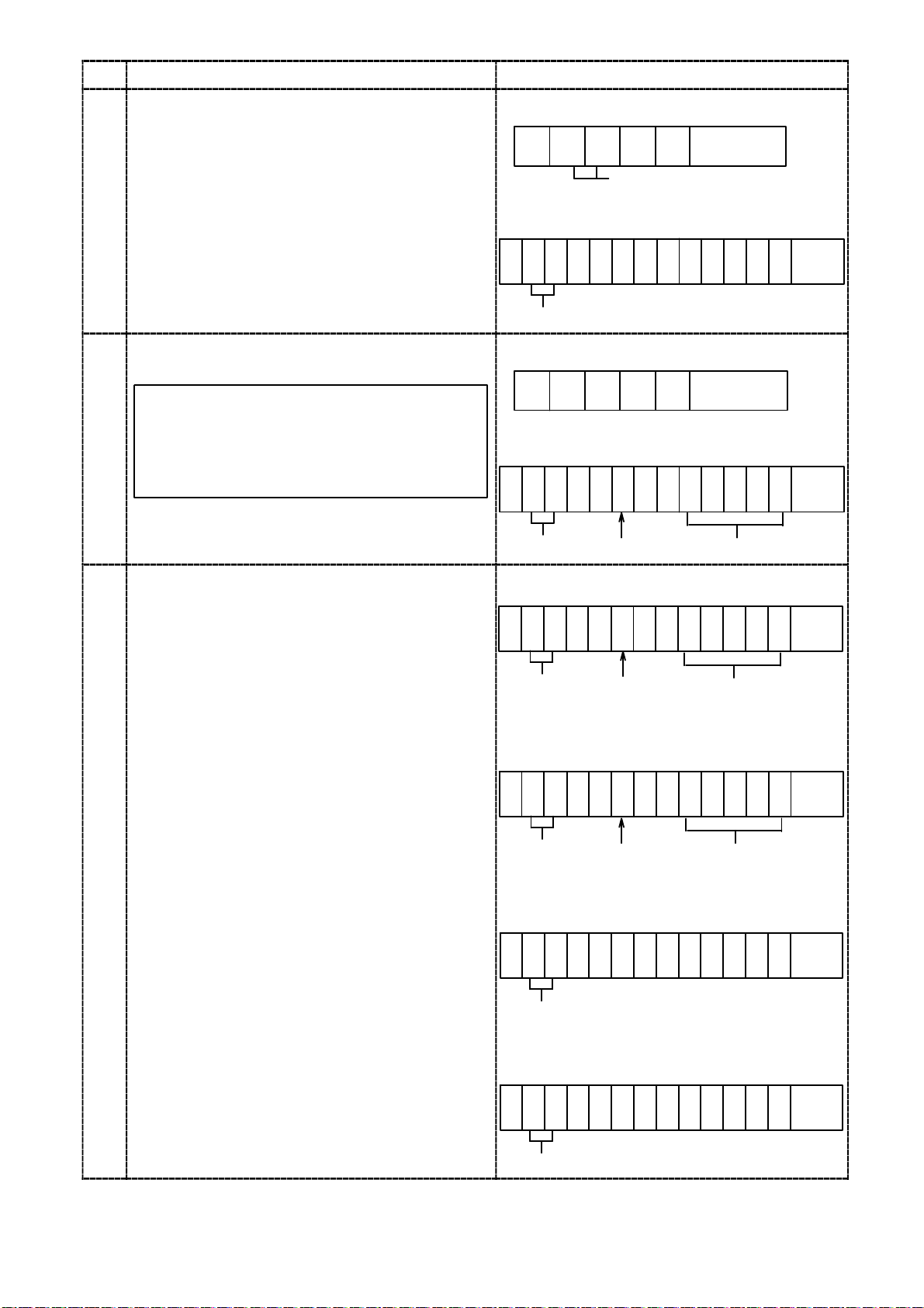
Procedures
→
Transmit the start command of the calibration
mode from the host.
Here, set the initial load condition.
The display in the load display section displays
“−RS−” and “the present load value”
alternately.
1
Transmit the reading out command of the
present load data from the host.
As for the load value read by the load data
reading out command, the decimal point
2
3
adheres to the decimal point position in
F01 when you set to add the decimal point
in F−56.
Transmit the display value to be displayed at
present by the command of zero fine adjustment.
According to the return data, proceed to the
following steps.
・When the Return result is the same as
Command
As the termination is in normal, proceed to the
next step.
・When the return data is “TE−L”
The zero fine adjustment range is less than −
2.5 mV/V. Set the zero fine adjustment range
from −2.5 mV/V to 2.5 mV/V.
・When the return data is “TE−H”
The zero fine adjustment range exceeds over 2.5
mV/V. Set the zero fine adjustment range from
−2.5 mV/V to 2.5 mV/V.
Command Host→CSD−891B
246
@ 0 0 0 4 Terminator
ID No.
Return CSD−891B→Host
2 4 6 8 10 12 14
@ 0 0 0 4 Z E R O Termi
ID No.
Command Host→CSD−891B
246
@ 0 0 2 1 Terminator
Return CSD−891B→Host
2 4 6 8 10 12 14
@ 0 0 2 1 0 Termi
ID No.
Command Host
2 4 6 8 10 12 14
@ 0 0 1 7 0 Termi
ID No.
Return CSD−891B→Host
・Normal termination
2 4 6 8 10 12 14
@ 0 0 1 7 0 Termi
ID No.
・When the range of zero fine adjustment is
less than −2.5 mV/V
2 4 6 8 10 12 14
Sign(+/−)
Sign(+/−) The setting load value
Sign(+/−)
The present load value
CSD−891B
The setting load value
-nator
-nator
-nator
-nator
@ 0 0 1 7 T E - L Termi
-nator
ID No.
・When the range of zero fine adjustment
exceeds over 2.5 mV/V.
2 4 6 8 10 12 14
@ 0 0 1 7 T E - H Termi
-nator
ID No.
69
Page 84

Procedure
4
Transmit the termination command of the
calibration mode from the host.
The calibration data is made effective and the
calibration mode is over.
The display in the load display section displays
the present load value.
Command Host→CSD−891B
246
@ 0 0 1 9 Terminator
ID No.
Return CSD−891B→Host
2 4 6 8 10 12 14
@ 0 0 1 9 E N D Termi
-nator
ID No.
70
Page 85

5−3−5. Span fine adjustment by the communication
Warning ● During the calibration is executing, be sure to make available for the
calibration set (Setting “00000” on F−97). Tare weight cancellation
clear, and to make cancellation (Setting of F−98) for compensated
data on zero set and set the OFF position of Zero tracking(Setting “
00000” on F−08 and F−09). If neglected, it returns the error
command (Error command No.01) to the host.
● The error command (Error command No.02) similarly returns to the
host when the command not suitable for the procedure is transmitted
during the calibration.
● Please match function No.F−50 to F−59 as to the communication to
host’s specification and change (Refer to the paragraph 8, 9−3 and
9−4). If neglected, the communication may not be executed correctly.
● This calibration method is possible when the optional RS−232C
interface or the RS−422/485 interface is mounted.
● When RS−232C interface is used, the ID No. becomes “00”.
● During the calibration, to interrupt the calibration “Calibration mode
interruption command” is transmitted, or press the key.
The calibration data is kept as before entering the calibration and
returns to the measurement mode.
Command Host→CSD−891B
246
@ 0 0 0 0 Terminator
ID number
Return CSD−891B→Host
2468101214
@ 0 0 0 0 Terminator
ID number
71
Page 86

Procedures
→
Transmit the calibration start command from
the host.
Here, set the maximum load that can be applied
within the maximum value on the load cell.
The display in the load display section displays
“−RS−” and “The present load value”
alternately.
1
Transmit the present load data reading out
command from the host.
As for the load value read by the load data
reading out command, the decimal point
adheres to the decimal point position in
2
F01 when you set to add the decimal point
in F−56.
Command Host→CSD−891B
246
@ 0 0 0 5 Terminator
ID No.
Return CSD−891B→Host
2 4 6 8 10 12 14
@ 0 0 0 5 S P A N Termi
-nator
ID No.
Command Host→CSD−891B
246
@ 0 0 2 1 Terminator
ID No.
Return CSD−891B→Host
2 4 6 8 10 12 14
@ 0 0 2 1 + 2 0 0 0 Termi
-nator
Transmit the display value to want to display
now by span fine adjustment command.
According to the return data, proceed to the
following steps.
・When the return data is as same as command.
As the termination is in normal, proceed to the
next step.
・When the return data is “SP−L”
The span fine adjustment range is less than 0.2
mV/V. Set the span fine adjustment range from
0.2 mV/V to 3.1 mV/V.
・When the return data is “SP−H”
The span fine adjustment range exceeds over
3.1 mV/V. Set the span fine adjustment range
3
from 0.2 mV/V to 3.1 mV/V.
ID No.
Command Host
2 4 6 8 10 12 14
@ 0 0 1 8 2 0 0 0 Termi
ID No.
Return CSD−891B→Host
・Normal termination
2 4 6 8 10 12 14
@ 0 0 1 8 2 0 0 0 Termi
ID No.
・When the span fine adjustment range is less
than 0.2 mV/V
2 4 6 8 10 12 14
@ 0 0 1 8 S P - L Termi
Sign(+/−)
CSD−891B
Sign(+/−) Setting load value
Sign(+/−)
ID No.
Present load value
-nator
-nator
Setting load value
-nator
・When the span fine adjustment range exceeds
over 3.1 mV/V
2 4 6 8 10 12 14
@ 0 0 1 8 S P - H Termi
ID No.
72
-nator
Page 87

Procedures
4
Transmit the termination command of the
calibration mode from the host.
The calibration data is made effective and the
calibration mode is over.
The display in the load display section displays
the present load value.
Command Host→CSD−891B
246
@ 0 0 1 9 Terminator
ID No.
Return CSD−891B→Host
2 4 6 8 10 12 14
@ 0 0 1 9 E N D Termi
-nator
ID No.
73
Page 88

5−3−6. Calibration procedure by the communication to apply registration again for zero point
only
Warning ● During the calibration is executing, be sure to make available for the
calibration set (Setting “00000” on F−97). Tare weight cancellation
clear, and to make cancellation (Setting of F−98) for compensated
data on zero set and set the OFF position of Zero tracking(Setting “
00000” on F−08 and F−09). If neglected, it returns the error
command (Error command No.01) to the host.
● The error command (Error command No.02) similarly returns to the
host when the command not suitable for the procedure is transmitted
during the calibration.
● Please match function No.F−50 to F−59 as to the communication to
host’s specification and change (Refer to the paragraph 8, 9−3 and
9−4). If neglected, the communication may not be executed correctly.
● This calibration method is possible when the optional RS−232C
interface or the RS−422/485 interface is mounted.
● When RS−232C interface is used, the ID No. becomes “00”.
● During the calibration, to interrupt the calibration “Calibration mode
interruption command” is transmitted, or press the key.
The calibration data is kept as before entering the calibration and
returns to the measurement mode.
Command Host→CSD−891B
246
@ 0 0 0 0 Terminator
ID number
Return CSD−891B→Host
2468101214
@ 0 0 0 0 Terminator
ID number
74
Page 89

Procedures
2
RS
and
ZERO
Transmit the calibration mode starting
command from the host.
The display in the load display section displays
“−RS−” and “ZERO”
1
Here, set the initial load condition.
Transmit the start command of “Calibration
procedure to apply registration again for zero
point only” from the host. Transmit the return
data from this instrument, and tare weight
cancellation is started.
The display in the load display section displays
“−RS−” and “ZERO”
As for the load value read by the load data
reading out command, the decimal point
adheres to the decimal point position in
F01 when you set to add the decimal point
in F−56.
Command Host→CSD−891B
246
@ 0 0 0 6 Terminator
ID No.
Return CSD−891B→Host
2 4 6 8 10 12 14
@ 0 0 0 6 T A R E Termi
-nator
ID No.
Command Host→CSD−891B
246
@ 0 0 1 3 Terminator
ID No.
Return CSD−891B→Host
2 4 6 8 10 12 14
@ 0 0 1 3 Z E R O Termi
-nator
75
Page 90

Procedures
e
Transmit the command of “Reading out in the
calibration” from the host.
According to the return data, proceed to the
following step.
・When the return data is “END“
As the termination is in normal, proceed to the
next step.
・When the return data is “TE−L”
The initial load is less than −2.5 mV/V.
After setting the initial load from −2.5 mV/V to
2.5 mV/V, proceed to the step 2.
・When the return data is “TE−H”
The initial load exceeds over 2.5 mV/V.
After setting the initial load from −2.5 mV/V to
2.5 mV/V, proceed to the next step.
・When the return data is “ZERO”
Until the return data becomes except “ZERO”,
3
repeat to transmit the command of “Status
reading out in the calibration” from the host.
The display in the load display section displays
“−RS−” and “SPAN” alternately.
Command Host→CSD−891B
246
@ 0 0 0 9 Terminator
ID No.
Command CSD−891B→Host
・Normal termination
2 4 6 8 10 12 14
@ 0 0 0 9 E N D Termi
-nator
ID No.
・When the input is low
2 4 6 8 10 12 14
@ 0 0 0 9 T E - L Termi
-nator
ID No.
・When the input is high
2 4 6 8 10 12 14
Transmit thetermination command of th
calibration mode from the host.
The calibration data is made effective and the
calibration mode is over.
The display in the load display section displays
the present load value.
4
@ 0 0 0 9 T E - H Termi
-nator
ID No.
・Under the calibration
2 4 6 8 10 12 14
@ 0 0 0 9 Z E R O Termi
-nator
ID No.
Command Host→CSD−891B
246
@ 0 0 1 9 Terminator
ID No.
Return CSD−891B→Host
・Normal termination
2 4 6 8 10 12 14
@ 0 0 1 9 E N D Termi
-nator
ID No.
76
Page 91

5−4. Selection of calibration methods on each condition
The instrument prepares calibration methods shown in the paragraph in 5−2. Calibration
procedures, we’ll explain some conditions to execute actual calibration here.
(1) When executing calibration on the new instrument.
(In case that our combined inspection has not executed.)
D When load condition and output condition of load cell are clarified.
(Required accuracy is less than 1/1 000 or so.)
→Proceed to the paragraph 5−4−1(1)
D When load condition and output condition of load cell are clarified.
(Required accuracy is more than 1/1 000 or so.)
→Proceed to the paragraph 5−4−1(2)
D When load condition is clarified, but output condition of load cell is unclear.
→Proceed to the paragraph 5−4−1(3)
D When exchanging with existing CSD−815 is required.
→Proceed to the paragraph 5−4−1(4)
(2) When making calibration again.
D When calibration only for tare weight is required.
(In case that our combined inspection has already executed, and the calibration
only for tare weight is required.)
D When fine adjustment on zero and span is required.
5−4−1. In case of executing the calibration on the instrument newly.
When the new instrument is purchased or reuse is desired with the new specific conditions,
execute the calibration with whichever procedure as follows:
(1) When the load condition and the output condition of load cell are clarified.
(In case of desired accuracy is less than 1/1000 or so.)
Warning ● The calibration accuracy obtained in this procedure is less than
1/1 000 or so. When precise accuracy more than 1/1 000 is necessary,
make calibration with actual load according to the paragraph 5−4−1
(2).
Besides, the accuracy described here is a combined accuracy of the
instrument and the strain gage applied transducer connected.
If there may exist another factors of error such as mechanical
elements and so on, it will become out of warranty, so care should be
taken fully.
● The rated output value for load cell applicable by the calculation
should be assumed as the value described on the “Inspection data”
individually.
77
Page 92

For example, we will show the calibration procedures as follows, that is, 3 points of load cells
with 3 mV/V of rated output and 5 t of rated capacity.
Tare weight 1.5 t
Weighing capacity 5 t
Maximum display 5 000
1
Calculate the output of load cell at maximum display from the above conditions. Check that
the calculated value should be within the range from 0.4 mV/V to 3.1 mV/V. If the value is out
of the range, calibration can’t be executed.
(Output of load cell at maximum display)
(Rated output)+(Rated output)+(Rated output)
=
3 mV/V+3 mV/V+3 mV/V
=
1 mV/V
=
2
After making the load cell to the initial load condition (tare weight), execute the calibration
according to the paragraph 5−2−1. In this case, input “5000” in the step 6, and input “1.0000”
in the step 8 individually. (When the calibration by communication is required, execute it
according to the paragraph 5−3−1.)
3
If necessity requires, apply zero/span fine adjustment according the paragraph 5−2−4, and
5−2−5. (When the calibration by communication is required, execute it according to the
paragraph 5−3−4 and 5−3−5.)
(2) When the both conditions of load and the output of load cell are clarified.
(In case that required accuracy is more than 1/1 000 or so.)
Number of load cells
3 points
×
3 points×5t
5t
×
(No. of load cells)×(Rated load)
Weighing capacity
Warning ● The accuracy obtained through the procedures of this calibration
consists from combined accuracy with the instrument and combined
strain gage applied transducer, the accuracy of weight used during the
calibration, error factors on mechanical and also error factors on
calibration works, that is, the total accuracy of these. If high accuracy
is required, full considerations should be made on each factor. If
neglected, there will be a case that desired accuracy may not be
obtained, so care should be taken fully.
When high accuracy is required, actual load calibration by using the weight and so on are
required.
For example, we’ll show the calibration procedures in the following conditions, that is, 3 points
of load cell with 3 mV/V of rated output and 5 t of rated capacity.
Tare weight 1.5 t
Weighing capacity 5 t
Maximum display 5 000
78
Page 93

1
Calculate the output of load cell at the maximum display from the above conditions.
Check that the calculated value at this point is within the range from 0.4 mV/V to 3.1 mV/V.
If the value is out of the range, calibration cant’ be executed.
(Output of load cell at maximum display)
(Rated output)+(Rated output)+(Rated output)
=
Number of load cells
3 mV/V+3 mV/V+3 mV/V
=
1 mV/V
=
2
After making the load cell to the initial load condition (tare weight), execute the calibration
3 points
×
5t
3 points×5t
×
(No. of load cells)×(Rated load)
Weighing capacity
according to the paragraph 5−2−3. In this case, input “5000” in the step 6, and input the load
value applied on the load cell in the step 8 individually. (When the calibration by
communication is required, execute it according to the paragraph 5−3−3.)
3
If necessity requires, apply zero/span fine adjustment according the paragraph 5−2−4, and
5−2−5. (When the calibration by communication is required, execute it according to the
paragraph 5−3−4 and 5−3−5.)
(3) When the load condition is clarified but the output condition of load cell is not clarified.
In the case of using the existing load detecting section, and adopting the new digital indicator
only, it is necessary to execute calibration after checking the output of load cell when its
output is not clarified.
For example, followings are calibration procedures when weighing capacity is 5 t and the
others are not clarified.
1
Set the instrument in the monitor mode according to the paragraph 7−18. In this condition,
the output level of load cell connecting with the instrument can be monitored up to approx.
3.100 0 with the unit of mV/V.
2
After making the load cell section to the initial load condition (tare weight), record the display
value on load display. This value is the output of load cell at the time of initial load condition.
3
Record the display value on load display after applying 5 t load on the load cell section. This
value is the output of load cell with weighing capacity applied.
4
From the load cell output at the time of initial load application recorded at ②, and load cell
output recorded at ③ at the time of application of weighing capacity, output of load cell at the
time of maximum display can be calculated according to the below formula.
Check that the calculated value is within the range from 0.4 mV/V to 3.1 mV/V. The
calibration can’t be executed if the value is out of the range.
(Load cell output at the time of the maximum display)
=(Load cell output at the weighing application)−(Load cell output at the initial load)
5
Quit the monitor mode of the instrument.
6
After making the load cell to the initial load condition (Tare weight), execute calibration
according to the paragraph 5−2−1. In this case, the accuracy is less than 1/1 000 or so.
At this moment, input each value, “5000” in the step 5 and another input is the value of
“Output of load cell at the maximum display” calculated from the ④ in the step 8. If the
accuracy more than of 1/1 000 or so is required, execute calibration according to the paragraph
5−2−3. And at the same time, input “5000” in the step 6 and also input “Load value going to
apply on load cell” in the step 8 individually. (When the calibration by communication is
required, execute it according to the paragraph 5−3−1 and 5−3−3.)
79
Page 94

7
As necessity requires, make fine adjustment on Zero and Span according to the paragraph
5−2−4 and 5−2−5. (When the calibration by communication is required, execute it according
to the paragraph 5−3−4 and 5−3−5.)
(4) When replacing the existing CSD−891B with a new one.
Warning ● The accuracy in this procedure is less than 1/1 000 or so.
If higher accuracy is required, make calibration by using the actual
load according to the paragraph 5−4−1(2).
Moreover, the accuracy described here is a combined accuracy with the
instrument and strain gage applied transducer connected.
When another error factors may exist, such as constructional error
factors or so, it will become out of warranty for accuracy, so care
should be taken fully.
When the load at the section of load cell can’t make it with initial load application due to
failure on the existing CSD−891B, execute calibration by referring to the procedures as below.
However, in case that the initial load condition can be obtained, make calibration according to
the procedures of (1) and (2).
1
According to the paragraph 8−1, read out and write down the function F−90 “Increment
value”, the F−91 “Maximum display value”, the F−93 “Zero calibration value”, and the F−94
“Span calibration value” in the existing CSD−891B.
2
According to the paragraph 4, replace the exiting CSD−891B with a normal instrument and
make connections.
3
After turning ON the normal instrument, make calibration according to the paragraph
5−2−2. In case of this, input the “Increment value” recorded at ① in the step 3, the
“Maximum display value” in the step 5 and the “Zero calibration value” in the step 7 and in
the same way, input “Span calibration value” in the step 9. (When the calibration by
communication is required, execute it according to the paragraph 5−3−2.)
80
Page 95

5−4−2. When the calibration is executed again
When purchasing a new instrument and our combined inspection has executed,
however, the tare weight has changed, or fine adjustment on zero and span are required, make
calibration with whichever the following methods.
(1) Calculation on tare weight only
(When our combined inspection has completed and calibration on only tare weight is
required.)
When the initial load (tare weight) has changed after completing the calibration, or when our
combined inspection has been made and the calibration only for the initial
load(tare weight) is required after the installation, proceed the calibration in the following
steps.
1
After setting the initial load (tare weight) on load cell section, execute calibration according to
the paragraph 5−2−6.(When the calibration by communication is required, execute it
according to the paragraph 5−3−6.)
(2) In case of executing fine adjustment on zero and span
Make adjustment according to the paragraph 5−2−4(Fine adjustment on zero), and 5−2−5
(Fine adjustment on span). (When the calibration by communication is required, execute it
according to the paragraph 5−3−4. (Fine adjustment on zero) and 5−3−5. (Fine adjustment
on span).)
Warning ● The accuracy obtained through the calibration procedures consists
from combined accuracy with the instrument and strain gage applied
transducer, the accuracy of weight used during the calibration, error
factors on mechanical and also error factors on calibration works, that
is , total accuracy of these.
If high accuracy is required, full considerations should be made on
each factor. If neglected, there will be a case that the desired accuracy
shall not be obtained.
5−5. Setting the prohibition against calibration
After completing all of the calibration procedures, setting can be made to prohibit any more
calibration again by setting the funciton(Related function F−97).
For details, refer to the paragraph 7−16.
81
Page 96

6. Operation procedure
We’ll show the operating procedures with keys located on the front panel.
Warning ● Each key operation should be made after interrupting the
measurement. If it is made during measurement, it may cause an
unexpected malfunction.
● Key operation in Measurement mode can be effective by pressing it for
about one second or so.
6−1. key
6−1−1. Operations in Measurement mode
(1) When operating in single
The Function mode can be entered, and the “FUNC” is shown on the load display section.
In this condition, setting on the Function or shifting to another modes can be available.
(2) When operation together with the
After pressing the
CHECK value set in F−11 turns ON, “CHECK” in the condition display lights on, and then
add the load value equivalent to the value set in F−11 on the load display value.
Again, after pressing the
makes to turn OFF the CHECK value and return to the former condition.
6−1−2. When operating in the other mode
After pressing the key in the condition of each setting mode, it returns to the measurement
mode.
6−2. key
6−2−1. When operating in the measurement mode
The condition which can set the comparator set value is entered, and LED in the load display
section light on and off. In this condition, the comparative value No. to be changed can be
selected.
And if you keep the instrument untouched for approx. 20 seconds, the Measurement mode can
be re−entered automatically.
key for more than one second, and operating together with the key,
key for more than one second, operation with pressing this key
key
82
Page 97

6−2−2. Operation is made in the other mode
(1) Carrying−over of set value
Pressing the
the setting value flashing on and off is going up from 10
(However, the range of carrying−over is different according to number of digits of set value
and the presence of sign.)
(2) Changeover of the function, etc.
The changeover of the various kinds of function in the function mode and the check mode can
be made.
(3) Decrement in the fine adjustment
When the
analog output, the decrement can be made in the target value.
key in the condition of displaying the various kinds of set value, the digit of
0
to 101,102,103and 104one by one.
key is pressed at the time of making fine adjustment on ZERO, SPAN and
● In the operation method of the paragraph 6−2−2(3), when the key is
pressed for more than about 1 second, each operation will be executed
continuously at a constant interval without ON/OFF operation of the
key.
6−3. key
6−3−1. Operation is made in the measurement mode
When the display value on load display section is within 10 % against the maximum display
value, (Refer to the Chapter 5.), the “0” display will be shown compulsively due to the zero set
function of this operation . As for details, refer to the paragraph 7−12.
6−3−2. Operation in the other mode
(1) Increment of the set value
By pressing the
value will increase per one count from 0, 1, 2, 3, 4, 5, 6, 7, 8, 9 and 0 again in order.
(2) Increment in the fine adjustment
When the
analog output, the increment can be made in the target value.
key with the condition of displaying various kinds of set values, the set
key is pressed at the time of making fine adjustment on ZERO, SPAN and
● In the operation method of the paragraph 6−3−2(2), when the key is
pressed for more than about 1 second, each operation will be executed
continuously at a constant interval without ON/OFF operation of the
key.
83
Page 98

6−4. key
6−4−1. Operation in the measurement mode
At the same time when the Tare weight cancellation (A/Z) works and the load display value
becomes the net weight display value, the “A/Z” on the status display lights up and load display
becomes “0”.
6−4−2. Operation in the other mode
(1) Calibration
The setting value is initialized in the each procedures of the calibration methods.
(2) Function mode
The function number and the setting value of the function is made compulsively to “0” in the
function mode.
(3) Setting of comparator
The set value is compulsorily made “0” with the set value of the comparator can set.
6−5. key
6−5−1. Operation in the measurement mode
At the same time when the function of the tare weight cancellation clear(A/Z OFF) works, and
the load display value becomes to the display value of the gross weight, “A/Z” in the condition
display section lights off.
6−6. key
When key is pressed, the changed set value is registered internally, and it comes off the
condition which can be set.
84
Page 99

7. Function and operation
7−1. External control input signal and Open collector output signal
The instrument is available to the external control through various kinds of input signals.
7−1−1. External control input signal
It operates by shortening with COM. (Terminal No.15).
Terminal
No.
10 ZERO When the indicated value on load display is within 10 % against the
11 HOLD While inputting the signal, the target selected with Function F−10 among
12 A/Z After the tare weight cancellation (A/Z) function works, “A/Z” in the
13 A/Z OFF Only when the tare weight cancellation (A/Z) function is working, the tare
14 LOCK During this signal input, “LOCK” in the condition display light on with
15 COM. The common of the external control input signal(Terminal No.10 to 14)
Name Operation
maximum display value, zero set function activates by the operation and
make the display “0” compulsively. (Same key operation in the paragraph
6−3−1.) As for the operational details, refer to the paragraph 7−12.
display, contact output, analog output and options will be frozen. As for
the operational details, refer to the paragraph 7−9.
condition display lights on with the display of the net weight in the load
display section, then the load display value becomes “0”. (Same key
operation in the paragraph 6−4−1.) As for operation details, refer to the
paragraph 7−11.
weight cancellation clear(A/Z OFF) works, and “A/Z” in the condition
display lights off with the display of the gross weight in the load display
section. (Same key operation in the paragraph 6−5−1.) As for operation
details, refer to the paragraph 7−11.
the lock(prohibit) of all keys.
and the open collector output (Terminal No.16 to 22).
● Operation of the input signal is executed after shortening for more
than 50 ms approximately. (Level and pulse width of 2, 5, 10 or 20 ms
is changeable. (Related function F−72)
● During the input of HOLD signal, when ZERO, A/Z or A/Z OFF signal
(or the
the target selected in the function F−10 is executed at the same time
of cancellation of HOLD signal.
● After inputting the HOLD signal in power−OFF condition, turn ON
the power, then the “HOLD” lights on the load display section. The
load value is shown simultaneous with the cancellation of HOLD
signal.
key on the front panel) is input, operation of HOLD on
85
Page 100

7−1−2. Open collector output signal
Terminal
No.
15 COM.
16 RUN
17 ERROR ON when the various kinds of error is occurred.
18 S0
19 S1 Open collector output for comparator S1
20 S2 Open collector output for comparator S2
21 S3 Open collector output for comparator S3
22 S4 Open collector output for comparator S4
Name Operation
The common for the external control input signal (Terminal No.10 to 14)
and Open collector output(Terminal No.16 to 22).
ON when this instrument is in the measurement mode. OFF when
CHECK is OFF.
Operated with whichever condition as follows by the setting F−33.
a) ON when the load display value≧(The maximum display value)
b)ON when the open collector output both of S1 and S2 are OFF
c) ON when the open collector output both of S1 and S3 are OFF
d)ON when the open collector output both of S1 and S4 are OFF
e) ON when the open collector output both S2 and S3 are OFF
f) ON when the open collector output both S2 and S4 are OFF
g) ON when the open collector output both S3 and S4 are OFF
h)Operated with whichever “open collector ON at more than the set
value” or “open collector ON at less than the set value”
i) Interlocked with HOLD LED
j) Interlocked with A/Z LED
k)Interlocked with LOCK LED
l) ON when the detection of stability
● COM.(Terminal No.15) is the common for the external control input
signal (Terminal No.10 to 14) and open collector output(Terminal No.
16 to 22).
● The comparator in the instrument executes comparative operations
synchronous with the A/D sampling rate.
86
 Loading...