

Page 1

MINEBEA Co., Ltd.
INSTRUCTION MANUAL
Digital indicator with CC−Link interface
CSD−815B−73
Note : Please read this Instruction Manual carefully before use.
Be sure to follow the items that require attention described in the manual.
Keep the manual at hand so that you can pick it up and read it as soon as
necessity requires.
EN294−1435
Page 2

Forwards
Thank you very much for your purchasing Minebea’s Digital Indicator with CC−Link
interface CSD−815B−73. This manual explains installation procedures and connecting
method and also operating method for the Digital Indicator with CC−Link interface
CSD−815B−73. When you will use this instrument as the specification with CC−Link
interface, make use of it properly after reading through the manual carefully.
Be sure to deliver the manual to the end user. Moreover, the end user should keep the
manual at hand after reading it over.
This manual is intended for the technical experts to read. When you read this instruction
manual, the program basic knowledge of a Mitsubishi general−purpose sequencer and the
basic knowledge of CC−LINK interface are needed.
●CC−LINK is an abbreviation of “Control & Communication Link”
●The contents of the manual may subject to change for improvement without notice.
I
Page 3

Marks and arrangements used in this manual
The following marks are attached to the explanation on the matters that indicate “Don’t do
this.”, “Take care.” and “For reference”.
Be sure to read these items where these marks are attached.
Warning ● Warning may cause injury or accident that may harm to the operator.
Do not do these things described here.
● Caution during operation and working.
Be sure to read the item to prevent malfunction.
About the view of this book
In this instruction manual, the connection method and use of the CC−Link interface
specification of the option for CSD−815B are explained. Please see the CSD−815B
instruction manual about other main body functions and a basic method of handling and
notes.
D CSD−815B instruction manual(DRW NO.EN294−1435*)
Moreover, please refer to the instruction manual on sequencer and sequencer side
CC−LINK interface for the sequencer program and CC−LINK.
II
Page 4

History of revision
Date Instruction Manual No. Details of revised point
Nov. 2010
DRW. NO. EN294−1435
First version
CSD−815B main body Ver.1.200 or later CC−Link
interface CARD Ver.04 or later
III
Page 5

CONTENTS
Forwards Ⅰ....................................................................
Marks and arrangements used in this manual Ⅱ....................................
About the view of this book Ⅱ....................................................
History of revision Ⅲ............................................................
1. General 1.................................................................
1−1. Features 1............................................................
2. Name and function of each point 2..........................................
2−1. Rear panel CC−Link I/F point 2..........................................
3. Connecting method 4......................................................
3−1. Connector pin configuration for communication 4...........................
3−2. Cable length 4.........................................................
3−3. Connection 4..........................................................
3−4. Notes fo connection 5..................................................
4. Setting of CC−Link connecting 6............................................
4−1. Detail of CC−Link setting 6..............................................
4−2. Setting of the station(Function F−85) 6....................................
4−3. Setting of baud rate(F−86
4−4. 32 bits data expression method(F−87) 7..................................
) 6.............................................
5. PCL memory explanation 8.................................................
5−1. Address 8.............................................................
5−2. Address map 9........................................................
5−2−1.Data detail 9..........................................................
5−2−2.Relay zone 14..........................................................
6. Operation method 22.......................................................
6−1. Writing the set value (Special data area) 22.................................
6−2. Writing/Reading by general command 23...................................
6−3. Shift to status where it is possible to communicate 25........................
6−4. CPU normal operation signal 25...........................................
7. Specifications of interface 26................................................
7−1. CC−Link interface spec 26...............................................
7−2. Accessory 26...........................................................
Page 6

1. General
This unit is a remote device station of CC−LINK Ver.1.10.
This unit can be connected with the mastering station of CC−LINK Ver.1.10.
1−1. Features
Main features for CSD−815B−73 are as follows :
(1) Because this unit can be controlled by using remote I/O and a remote register of the sequencer,
the program volume of the sequencer can be reduced.
(2) Wiring with the sequencer can be reduced.
1
Page 7
2. Name and function of each point
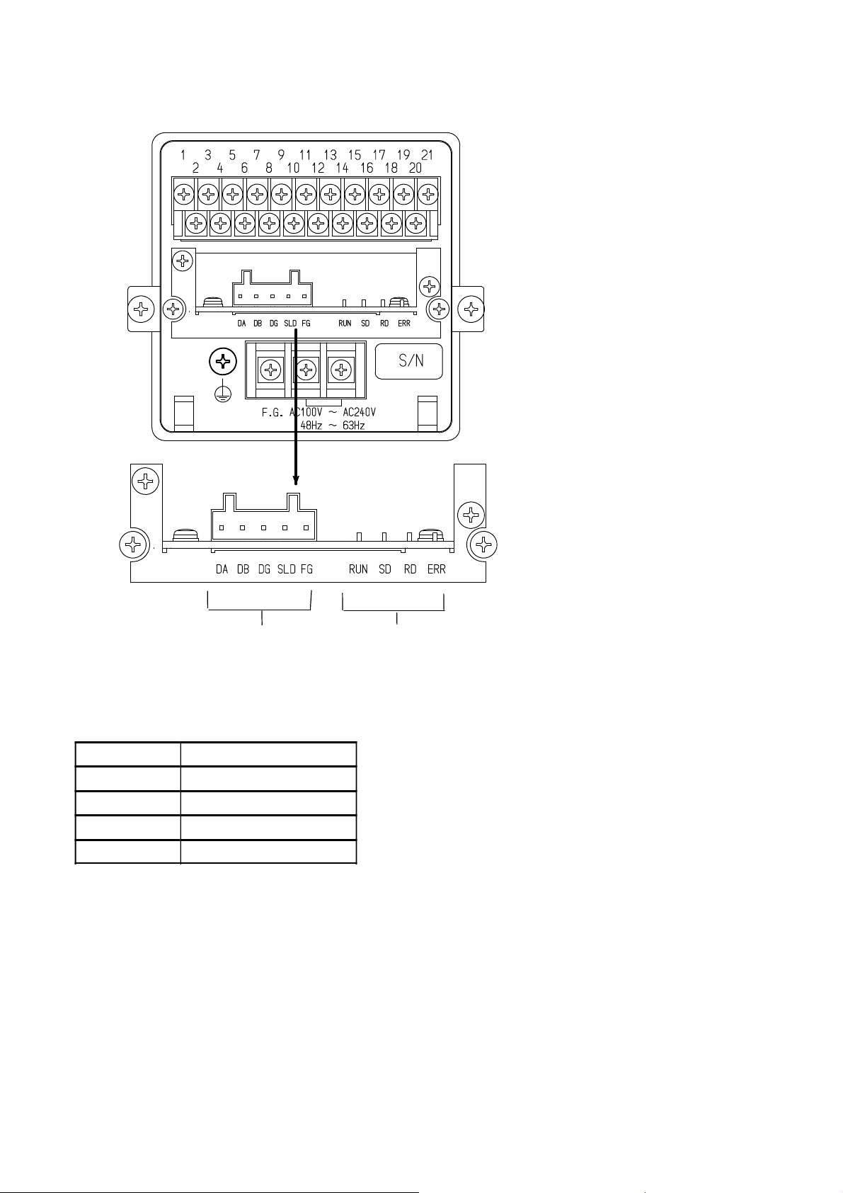
2−1. Rear panel CC−Link I/F point
Connector for communication
(1) Connector for communication terminal block
Connector type terminal block for CC−LINK interface.
Connector type terminal block pin configuration is as follows.
DA
DB Signal cable DB side
DG Signal cable ground
SLD Shield
FG Frame ground
Suitable plug:721−105/037−000 (WAGO) ※to be attached.
“SLD” and “FG” are connected in the instrument.
The internal circuit and photo coupler are insulated.
Signal cable DA side
Status LED
2
Page 8

(2) Status LED
The communication status is expressed with four LED.
LED Name
RUN ・Normal ・In the reset
SD ・Sending − −
RD ・Receiving − −
ERR ・Abnormal setting
・CRC error occurs.
・Trouble
Light on Light off Light on/off
・unavailable to
communication
・Normal ・When setting changes
−
3
Page 9
3. Connecting method
3−1. Connector pin configuration for communication
Refer to “2−1. Rear panel(1) Connector for communication terminal block”.
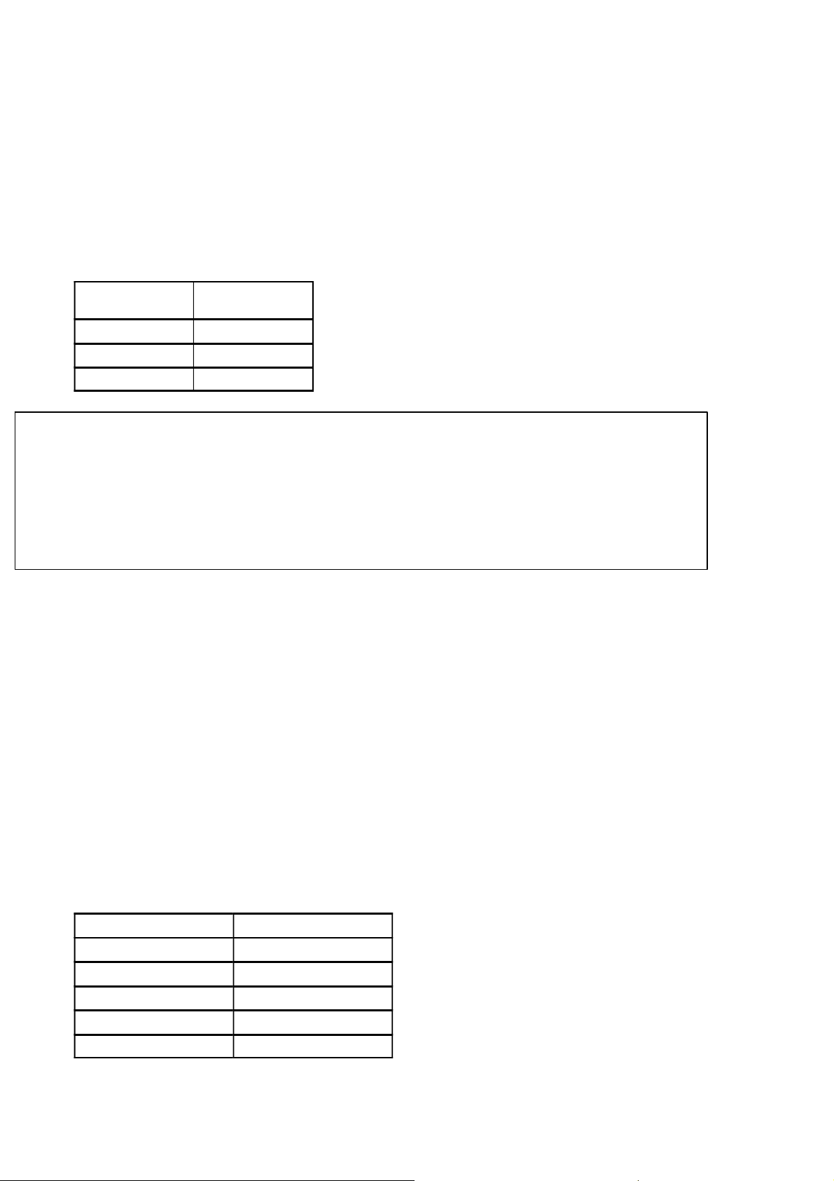
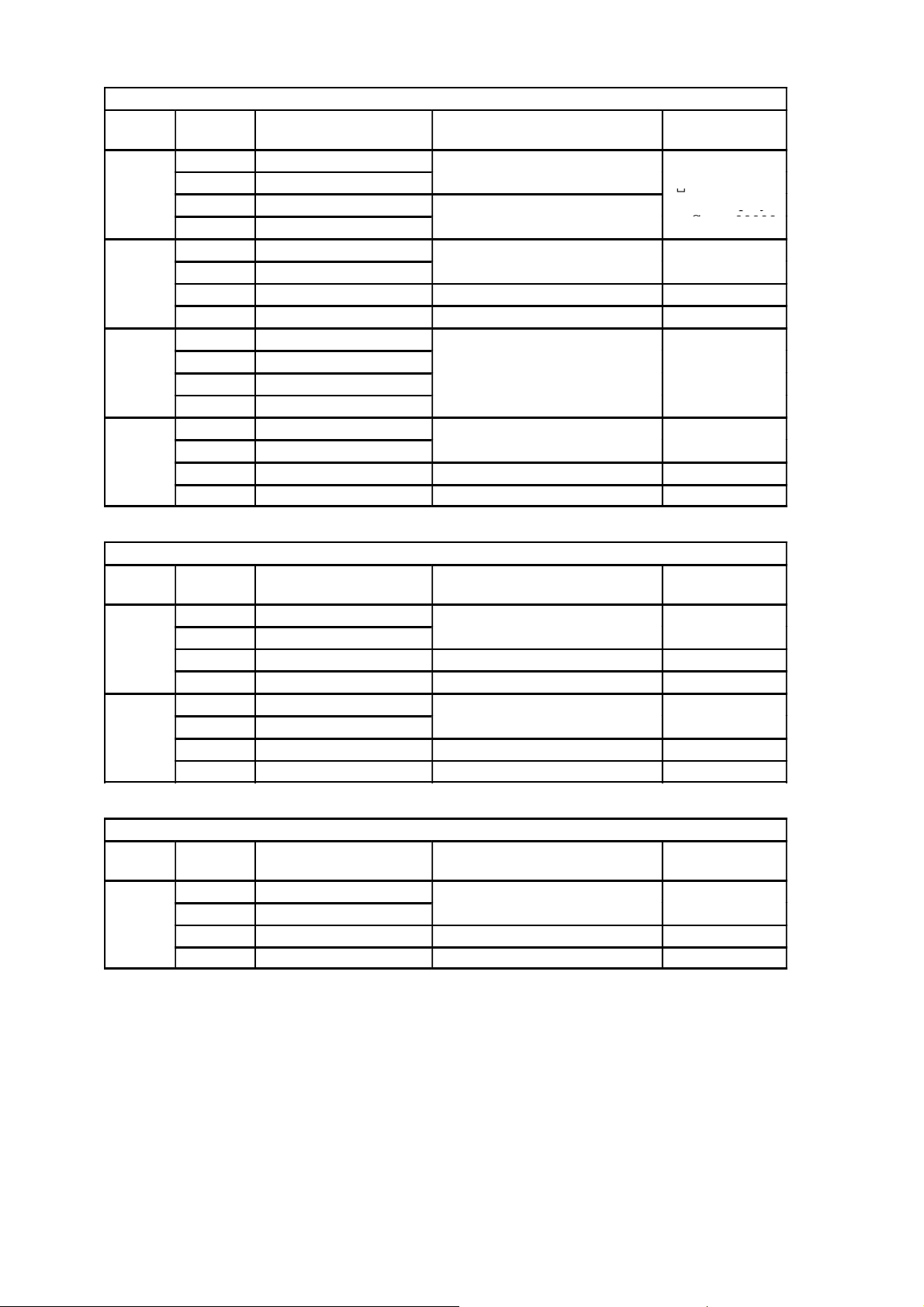
3−2. Cable length
Relation of baud rate and total extension length as follows.
Baud rate
156 kbps 1 200 m or less
625 kbps 600 m or less
2.5 Mbps 200 m or less
5 Mbps 150 m or less
10 Mbps 100 m or less
Cable length
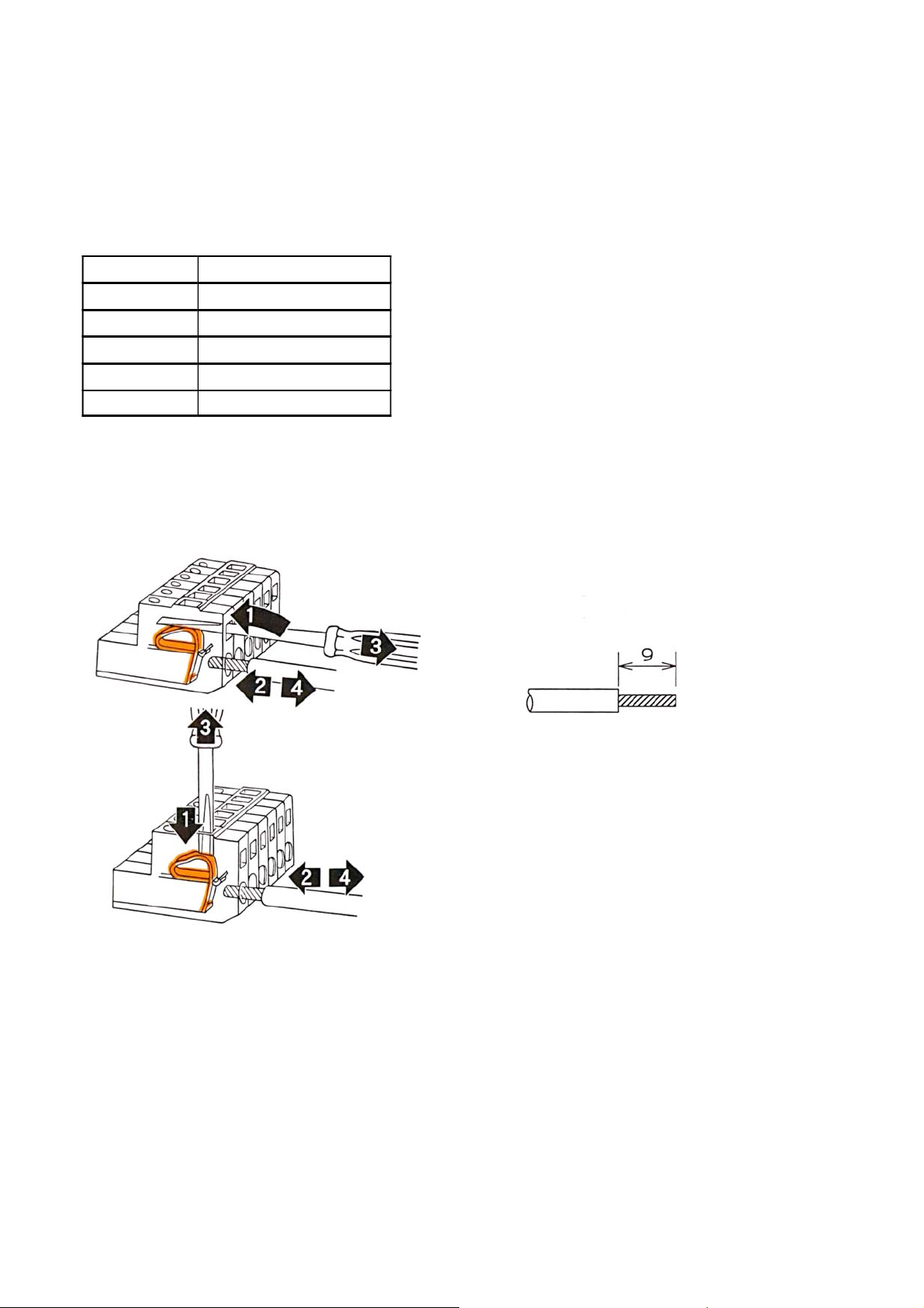
3−3. Connection
Please follow the instruction of connecting wires on the sequencer instruction manual about
connecting wires.
Striped electrical cable length
1) Put in the driver minus type.
2) Insert the electrical cable.
3) Pull out the driver minus type.
4) Confrim wire connection by a few tension.
4
Page 10

3−4. Notes of Connection
・When the wiring, be sure to the instrument power supply is OFF.
・Do not supply the AC power until complete the installation. This instrument does not have
power switch (ON/OFF).
・Do not fell or make a strong impact on this instrument rear pannel terminal block because it is
made of resin.
・
Striped electrical cable tip length is 9 mm.
・Cables which connecting this instrument isolate from noise sources, for example, power supply
line and I/O for control’s as much as possible.
・Be sure to connect the ground wire must be D single ground. Do not common the
ground with a kind of power supply.
・For CC−link cable connection, use twist pear cable wire with shield(Cable for CC−link) and
connect the shield in terminal block’s SLD terminal or F.G.terminal.
●Connect the termination to the CC−Link connector to electrical
termination which is far from PLC as possible.
●Use the connecting cable for CC−Link.
5
Page 11
4. Setting of CC−Link connecting
Please set the following in the function mode when you use CC−LINK interface.
Please refer to clause 8−1 of the CSD−815B instruction manual for ”Method of setting the function”.
4−1. Detail of CC−Link setting
Setting of the station(Function F−84)
The station of CC−LINK is set.
The range which can be set is “0”−“2”.
Default is set as [2].
F−84
0 1 station
1 2 stations
2 4 stations
Occupied
stations No.
●Setting changes for occupied stations No is corresponding to this
software after ROM Ver. 1200 and after CC−Link I/F CARD software
ROM Ver. 04.
Before ROM Ver. 1.100 and Ver. 03 is fixed 4 station occupied station
No.
4−2. Setting of the station(Function F−85)
Excute the setting of the station.
When it is 1 occupied station: selectable from station No 01 to 64.
When it is 2 occupied station: selectable from station No 01 to 63.
When it is 4 occupied station: selectable from station No 01 to 61.
The occupied station of this instrument is 1., 2, 4 stations.
For example, when the station number is assumed to 1 station and station No is set as 01, 01 to 04
stations are occupied. Therefore, the station number must not overlap.
Default is set as [01].
4−3. Setting of baud rate(F−86)
Excute the setting baud rate (unit: bps).
The range which can be set is from [0] to [4].
Default is set as [0]. Each setting value for baud rate is as fallow.
F−86 setting value
0 156 kbps
1 625 kbps
2 2.5 Mbps
3 5 Mbps
4 10 Mbps
Baud rate
6
Page 12

4−4. 32 bits data expression method(F−87)
Excute the setting of 32 bits data expression method.
The range which can be set is [0] or [1].
Default is set as [0]. Each setting value for 32 bits data expression method is as fallow.
F−87 setting value
0 Expression of standard binary
1 Highest bit sign
Load value F−87 Lower 16 bit Upper 16 bit
−1
−10
−99999
32 bits data expression method
0 FFFFH FFFFH
1 8000H 0001H
0 FFFFH FFF6H
1 8000H 000AH
0 FFFEH 7961H
1 8001H 869FH
Setting value is valid when the power rebooting. In case of changing the
setting, excute the power rebooting.
7
Page 13

5. PLC memory explanation
i
a
g
Station
R
emote
R
emote
R
3
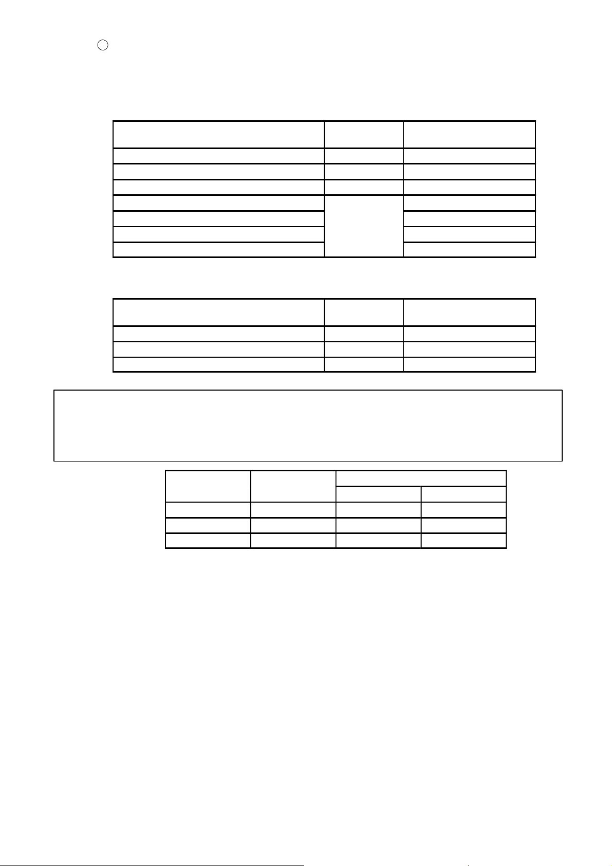
5−1. Address
A remote I/O(RX/RY:Bit handling register) and a remote register(RWw/RWr:Word handling register)
secures the zone in the master station depends on the occupied station number. As shown in the table
below in case of this unit.
Occupied station number
Type
Remote input 128 points 64 points 32 points
Remote output 128 points 64 points 32 points
Remote
register
The address number of the remote station allocated to the mastering station is as shown in the table
below.
Station
No.
0
1
2
Master→
Remote
Remote→
Master
Remote Remote
input
− − − −
RX0000 RY0000 RWw0000 RWr0000
00E0 0160 01E0 02E0
RX0020 RY0020 RWw0004 RWr0004
00E2 0162 01E4 02E4
RX0040 RY0040 RWw0008 RWr0008
00E4 0164 01E8 02E8
Occupies 4
stations
16 points 8 points 4 points
16 points 8 points 4 points
output
Occupies 2
stations
Remote register
Master→Remote Remote→Master
Occupies 1
station
Remarks
I/O for each 16 points
s occupiedas
system area.
emarks
Specify the master station
〜
10
〜
64
RX0120 RY0120 RWw0024 RWr0024
00F2 0172 0204 0304
RX07E0 RY07E0 RWw00FC RWr00FC
015E 01DE 02DC 03DC
8
Page 14

5−2. Address map
①
S
32bi
①
S
32bi
①
S
32bi
S
l
data
a
Undefined
32bi
Undefined
32bit3
Undefined
32bi
②
G
l
data
a
32bi
①
S
32bi
S
l
data
a
①
S
32bi
②
G
l
data
a
32bi
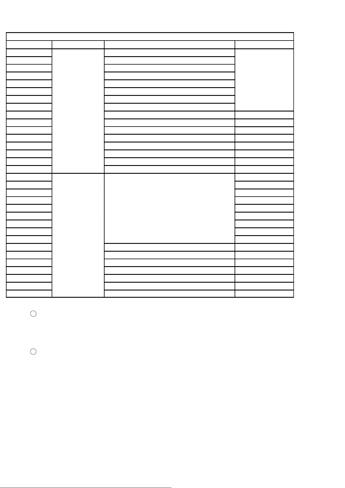
In this paragraph, the address of “Remote input”, “Remote output”, and
“Remote register” when the station Number of [1] is set. Please note
that the address is different when you set the station number except
No.[1].
5−2−1.Data detail
(1) Remote register(Master→This instrument)
Occupies 4 stations
Station
1
2
4
Buffer
Address
01E0 RWw0000
01E1 RWw0001
01E2 RWw0002
01E3 RWw0003
01E4 RWw0004
01E5 RWw0005
01E6 RWw0006
01E7 RWw0007
01E8 RWw0008
01E9 RWw0009
01EA RWw000A
01EB RWw000B
01EC RWw000C
01ED RWw000D
01EE RWw000E ③Command No.(Return) 8 bit
01EF RWw000F ④Operating mode(Return) 8 bit
Register
Master→CSD−815B
Contents Remarks
0 set value
1 set value
2 set value
enera
are
t
t
t
pecia
t
t
t
are
Station
1
2
Occupies 2 stations
Buffer
Address
01E0 RWw0000
01E1 RWw0001
01E2 RWw0002
01E3 RWw0003
01E4 RWw0004
01E5 RWw0005
01E6 RWw0006 ③Command No.(Return) 8 bit
01E7 RWw0007 ④Operating mode(Return) 8 bit
Register
Master→CSD−815B
9
Contents Remarks
0 set value
1 set value
enera
t
t
are
pecia
t
are
Page 15

Occupies 1 station
U
d
S
l
data
a
Station
Buffer
Address
Register
Master→CSD−815B
Contents Remarks
01E0 RWw0000
01E1 RWw0001
1
01E2 RWw0002
nuse
64bit
pecia
01E3 RWw0003
Remote register(Master station→This instrument)
1
Special data area(4 stations ,2 stations )
When the set value is registered by using the set value writing request (request 1), the set value
is set in each area.
Details of each set value are shown as follow,
set value from S0 to S2
Execute the setting of the comparative data.
Data type :32 bits binary with + or −
Setting range :−99 999〜99 999
2
General data area(4 stations ,2 stations )
When the command order is executed by using the general command request (request 2), the
set value or the operating order code is set in this area.
Data type :32 bits binary with + or −
Range of setting value:−99 999〜99 999
are
3
Command No.(4 stations ,2 stations )
When the command order is executed by using the general command request (request 2), the
command No. is set in this area.
The content of the general data area is set depending on the command set in this command No.
Data type :8 bits binary
Range of setting value :0〜255
4
Operation mode(4 stations ,2 stations )
When the operation mode is a changeover and is gotten by using the operation mode
changeover request (request 3), the mode number is set in this area. Mode only [0] corresponds
in the current state, and write [0] only.
Data type :8 bits binary
Range of setting value :0〜255 (However, [0] only corresponds in the current status.)
10
Page 16
5
Decimal
a
Commands list(4 stations ,2 stations )
When the command order is executed by using the general command request (request 2), the
value set in command No. and the general data area is indicated as follows;
Writing the set value and operation request (Writing/Reading out selection=Writing [OFF])
Setting value or command request
S0 10 −99 999〜99 999
S1 11 −99 999〜99 999
S2 12 −99 999〜99 999
Tare weight cancellation ON(A/Z ON) 14
Tare weight cancellation OFF(A/Z OFF)
Zero set ON(ZERO)
Reset of sequence error 36
Reading out the setting value(Selection of writing/Reading out=Reading out[ON])
Setting value or Command request
S0 10 −99 999〜99 999
S1 11 −99 999〜99 999
S2 12 −99 999〜99 999
Command No.
(RWw000E)
0
Command No.
(RWw000E)
General data area
(RWw000C〜RWw000D)
15
16
General data area
(RWw000C〜RWw000D)
Numeric representation of a remote register is as shown in the table
below as a rule. However, the negative numeric expression is different
according to setting F−87. Please refer to the paragraph 4−1.
Decimal
number
0 0000H 0000H 0000H
1 0001H 0000H 0001H
10 000AH 0000H 000AH
16bitsdat
Upper position Lower position
32 bits data
11
Page 17
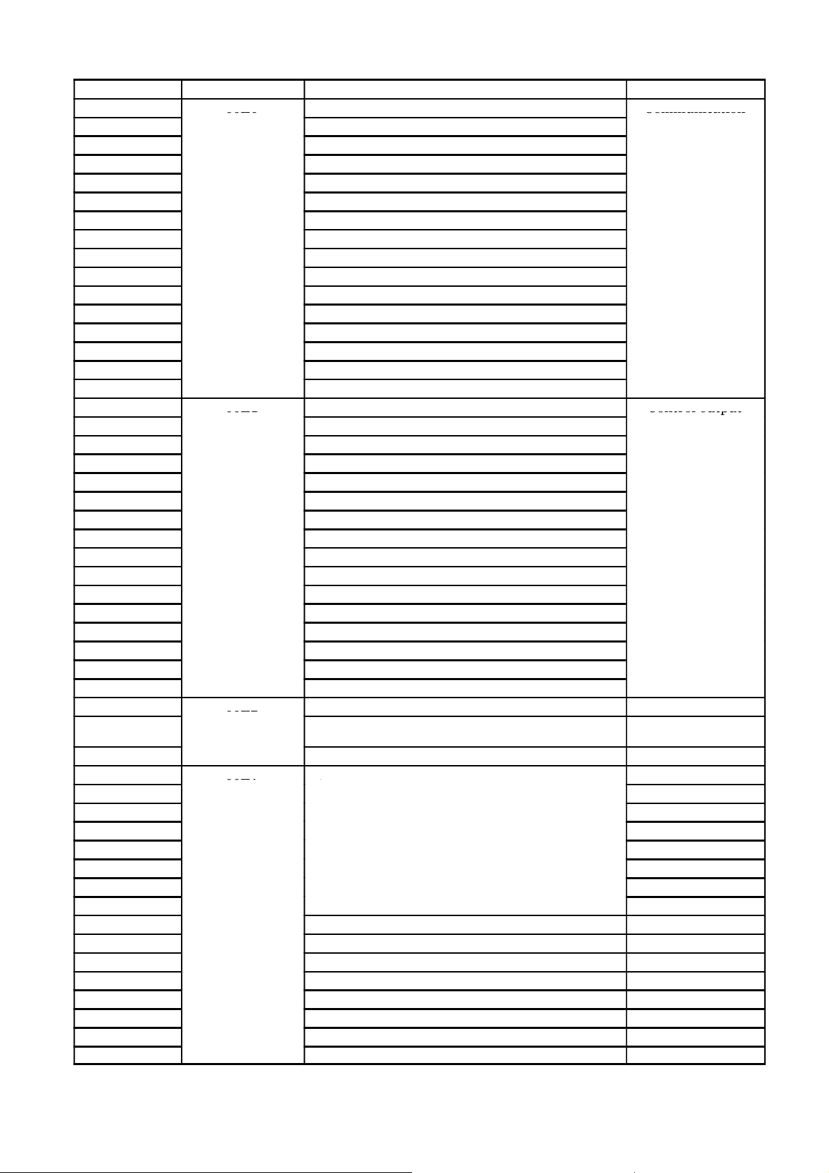
(2) Remote register(Instrument→Master)
OLdisplay
①
N
OL
display
:
Set
99999
②
G
py
Undefined
3
Undefined
⑤
G
l
data
a
g
⑧
Indicate
value(NET
weight
⑤
G
l
data
a
g
⑧
Indicate
value(NET
weight
Station
Buffer
Address
Register
Master→Instrument
02E0 RWr0000
02E1 RWr0001
1
02E2 RWr0002
02E3 RWr0003
02E4 RWr0004
02E5 RWr0005
2
02E6 RWr0006 ③Error code
02E7 RWr0007
02E8 RWr0008
02E9 RWr0009
02EA RWr000A
02EB RWr000B
02EC RWr000C
02ED RWr000D
4
02EE RWr000E ⑥Command No.(Response)
02EF RWr000F ⑦Operation mode(Response)
Occupies 4 stations
et weightvalue
ross weightvalue
④Error assistance code
enera
Contents Remarks
:Set 99999
−OL display
:Set −99999
are
Station
1
2
Station
1
Occupies 2 stations
Buffer
Address
02E0 RWr0000
02E1 RWr0001
Register
Master→Instrument
Contents Remarks
⑧Indicate value(NET wei
value/ GROSS weight value)
02E2 RWr0002 ③Error code
02E3 RWr0003
④Error assistance code
02E4 RWr0004
02E5 RWr0005
enera
are
02E6 RWr0006 ⑥Command No.(Response)
02E7 RWr0007 ⑦Operation mode(Response)
Occupies 1 station
Buffer
Address
02E0 RWr0000
02E1 RWr0001
Register
Master→Instrument
Contents Remarks
⑧Indicate value(NET wei
value/ GROSS weight value)
02E2 RWr0002 ③Error code
02E3 RWr0003
④Error assistance code
ht
ht
12
Page 18
1
Net weight value(4 stations ,2 stations )
Area for displaying the net weight value
Data type :32 bits binary with + or −
Range of setting value :−99 999〜99 999
2
Gross weight value(4 stations )
Area for displaying the gross weight value
Data type :32 bits binary with s+ or −
Range of setting value :−99 999〜99 999
3
Error code(4 stations ,2 stations ,1 station )
Refer to below table of ④ error assistance code too.
Area for displaying the error No. generating in the main body of the indicator.
Data type :16 bits binary
Range of setting value :0〜255
4
Error assistance code(4 stations ,2 stations ,1 station )
Data type :16 bits binary
Range of setting value :0〜255
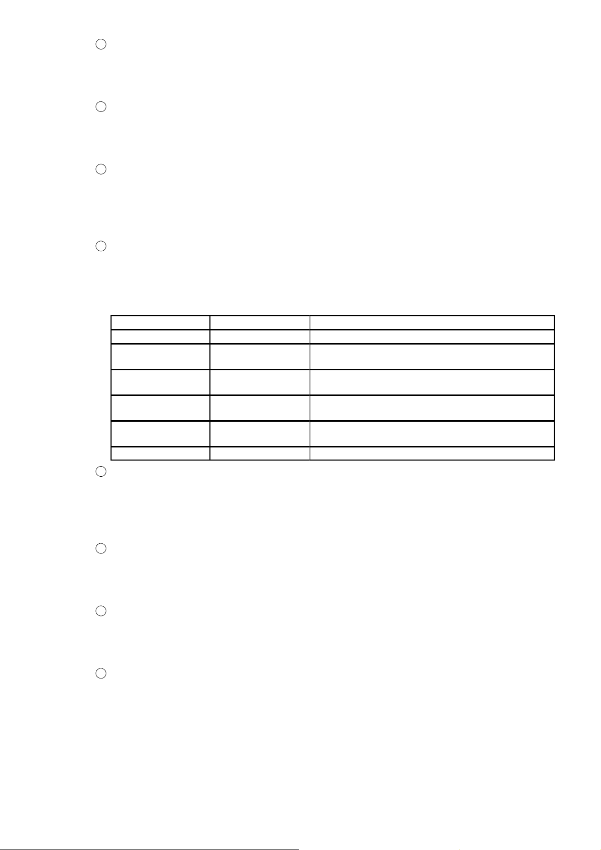
Error code
Error support code Error contents
0 0 No error
99 0
1 1
1 2
1 13
In case of setting the unspecified data in
command No.
In case of the instrument is “Calibration mode”,
“Check mode” and “Monitor mode”.
In case of setting the ZERO or A/Z at the
prohibition condition,
In case of the data setting other than specification
in general data area,
1 14 In case of connecting error of internal
5
General data area(4 stations ,2 stations )
When the setting value reading out command is ordered by using the general command
request (Request 2), this area displays the setting value.
Data type :32 bits binary with + or −.
Range of setting value :−99 999〜99 999
6
Command No.(Response)(4 stations ,2 stations )
When the command order is executed by the general command request (Request 2), this area
displays that command No.
Data type :8 bits binary
7
Operation mode (Response)(4 stations ,2 stations )
When the changeover of the operation by the operation mode changeover request (Request 3),
this area displays the mode.
Data type :8 bits binary
8
Indicate value(NET weight/ GROSS weight) (2 stations ,1 station )
It is area which showing the GROSS weight value or NET weight value.
Data type :32 bits binary with + or −
Range of setting value :−99 999〜99 999
13
Page 19
5−2−2.Relay zone
g
0162
0166
0167
y
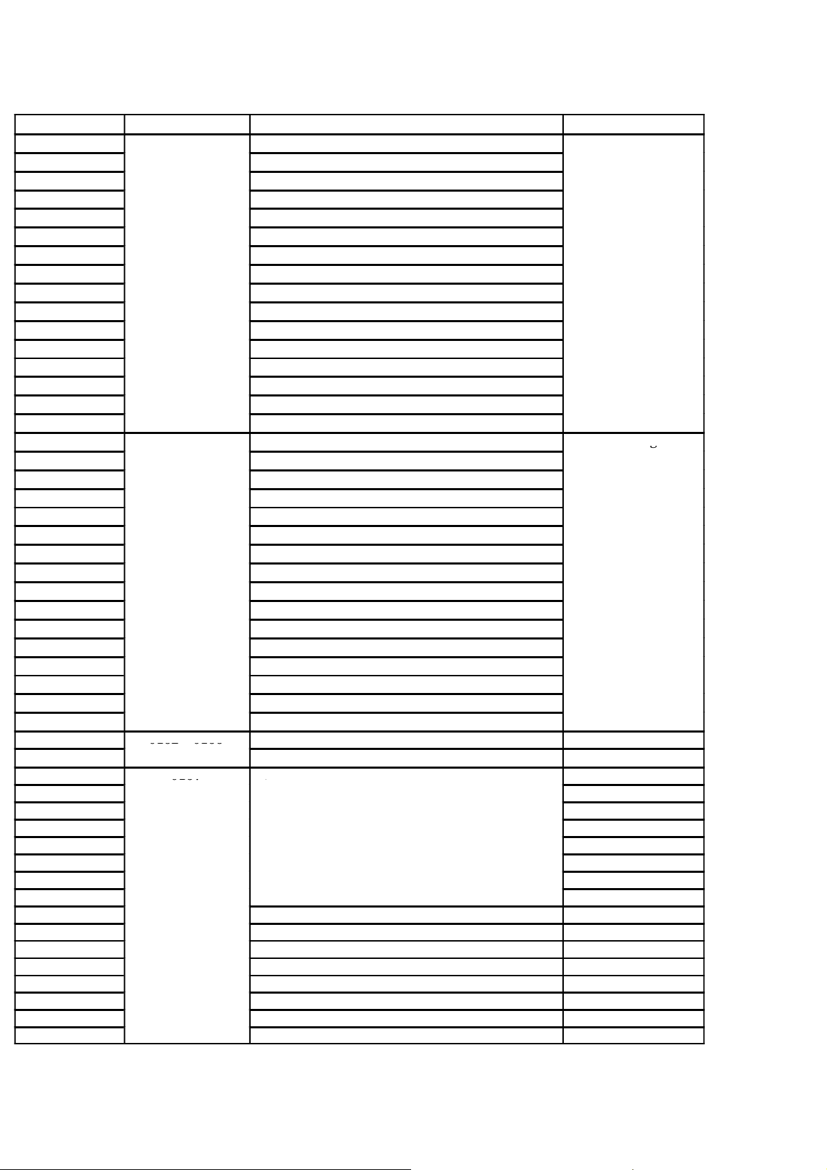
(1) Remote input (Master→This instrument) Occupies 4 stations
Device NO. Buffer address Contents Classification
RY0000
RY0001
RY0002
RY0003
RY0004
RY0005
RY0006
RY0007
RY0008
RY0009
RY000A
RY000B
RY000C
RY000D
RY000E
RY000F
RY0010
RY0011
RY0012
RY0013
RY0014
RY0015
RY0016
RY0017
RY0018
RY0019
RY001A
RY001B
RY001C
RY001D
RY001E
RY001F
・
RY006F
RY0070
RY0071
RY0072
RY0073
RY0074
RY0075
RY0076
RY0077
RY0078
RY0079
RY007A
RY007B
RY007C
RY007D
RY007E
RY007F
0160
0161
0162〜0166
0167
①Setting value writing request (Request 1)
②General command request (Request 2)
③Selection of writing/Reading out. (R/W)
④Operation mode changeover request (Request 3)
⑤ZERO
⑥A/Z ON
⑦A/Z OFF
System reservation zone
⑧Initial data proseccing complete flag
⑨Initialed data set request flag
⑩Error reset request flag
Communication
Control signal
14
Page 20
Occupies 2 stations
g
0162
0163
y
Device NO. Buffer address Contents Classification
RY0000
RY0001
RY0002
RY0003
RY0004
RY0005
RY0006
RY0007
RY0008
RY0009
RY000A
RY000B
RY000C
RY000D
RY000E
RY000F
RY0010
RY0011
RY0012
RY0013
RY0014
RY0015
RY0016
RY0017
RY0018
RY0019
RY001A
RY001B
RY001C
RY001D
RY001E
RY001F
・
RY002F
RY0030
RY0031
RY0032
RY0033
RY0034
RY0035
RY0036
RY0037
RY0038
RY0039
RY003A
RY003B
RY003C
RY003D
RY003E
RY003F
0160
0161
0162
0163
①Setting value writing request (Request 1)
②General command request (Request 2)
③Selection of writing/Reading out. (R/W)
④Operation mode changeover request (Request 3)
⑤ZERO
⑥A/Z ON
⑦A/Z OFF
⑪Select NET weight value/GROSS weight value
System data zone
⑧Initial data proseccing complete flag
⑨Initialed data set request flag
⑩Error reset request flag
Communication
Control signal
15
Page 21
Occupies 1 station
Device NO. Buffer address Contents Classification
RY0000
RY0001
RY0002
RY0003
RY0004
RY0005
RY0006
RY0007
RY0008
RY0009
RY000A
RY000B
RY000C
RY000D
RY000E
RY000F
RY0010
RY0011
RY0012
RY0013
RY0014
RY0015
RY0016
RY0017
RY0018
RY0019
RY001A
RY001B
RY001C
RY001D
RY001E
RY001F
0160
0161
⑤ZERO
⑥A/Z ON
⑦A/Z OFF
⑪Select NET weight value/GROSS weight value
System data zone
⑧Initial data proseccing complete flag
⑨Initialed data set request flag
⑩Error reset request flag
Communication
1
Setting value writing request (Request 1)
Requests writing of the data set in special data area. (RWw0000−RWw000B).
ON :In the request of writing
OFF :After confirming “Setting value writing response (Response 1)” of remote input.
2
General command request (Request 2)
Writing/Reading out by the command order is requested.
Please use together with writing/reading out selection (R/W).
ON :In the request of writing/reading out
OFF :After confirming “Setting value writing response (Response 2)” of remote input.
16
Page 22

3
Selection of writing or reading out(R/W)
Select writing or reading out by the command order.
Writing the data set in general−purpose data area (RWw000C−RWw000D) by command NO.
(RWw000E) is ordered for writing.
Reading out the data set in general−purpose data area (RWw000C−RWw000D) by command
NO. (RWw000E) is ordered for reading out.
ON :Reading out
OFF :Writing
4
Operation mode changeover request (Request 3)
Requests the writing of the data set in operation mode (RWw000F).
ON :In the request of writing request.
OFF :After confirming “Operation mode changeover response (Response 3)” of remote
input.
5
ZERO
Execute the zero set.
ON :In requesting the execution of zero set.
OFF :Normal
6
A/Z ON
Start an automatic zero.
ON :In the request of starting the automatic zero.
OFF :Normal
7
A/Z OFF
Clear the automatic zero.
ON :In the request of A/Z clear.
OFF :Normal
8
Initial proseccing complete flag
Send the initial proseccing complete flag when it will recive [RX078] command,
ON :Data clear request
OFF :Normal
9
Initial data setting request flag
Request the initialization of the instrument.
ON :In the request of default setting.
OFF :Normal
10
Error re−set requesting flag
When the error generation is notified with error condition command [RX007A], request the
release of the error.
ON :In the request of clear
OFF :Normal
11
Indicate value NET weight value/GROSS weight value comunand(2 stations, 1station)
Select the indication valiue [NET] or [GROSS] in remote resistor area when the station
occupies 1 or 2,
ON :NET weight value (Same value of remote resistor at the occupies 4 stations)
OFF :GROSS weight value (Same value of remote resistor at the occupies 4 stations)
17
Page 23

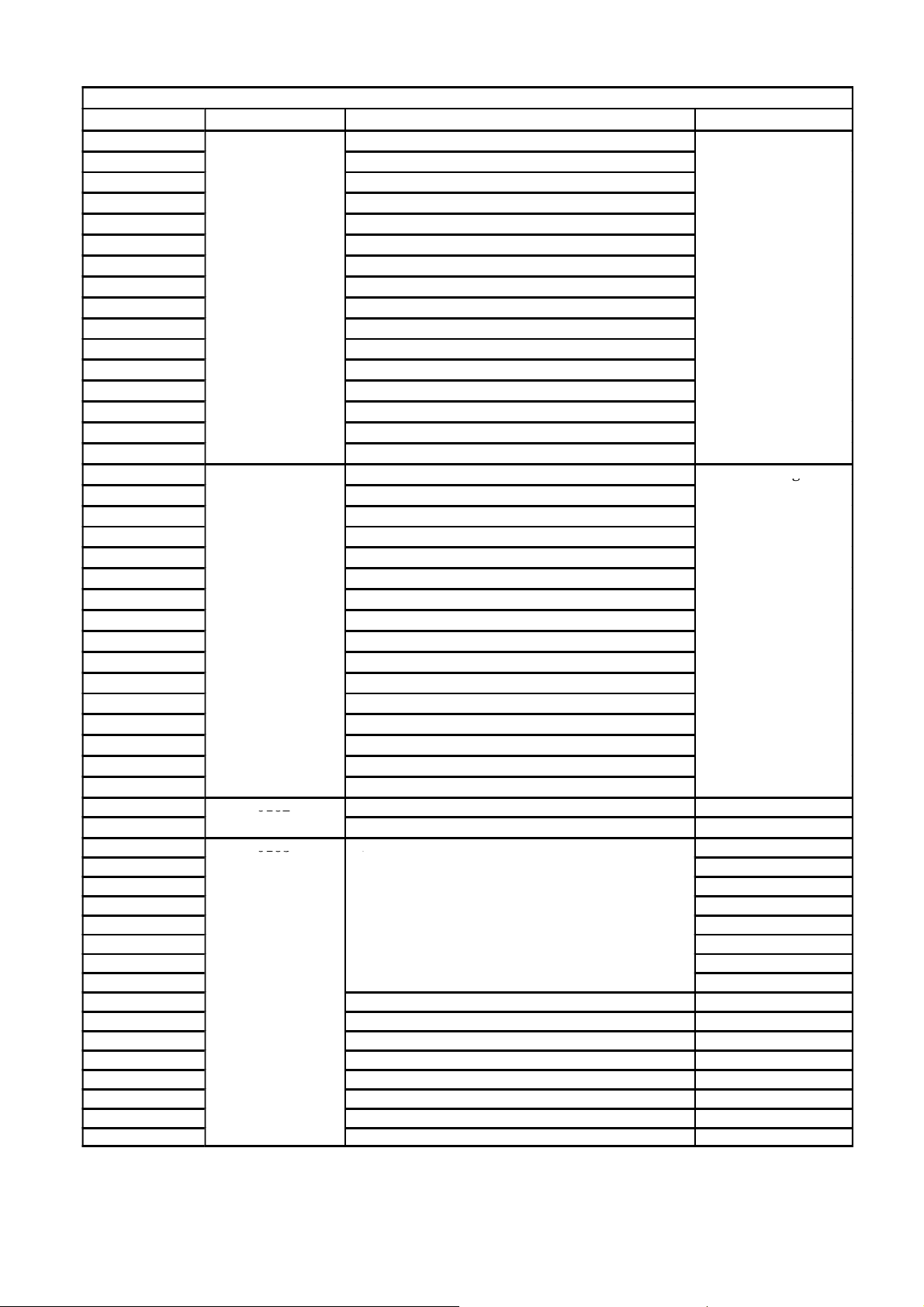
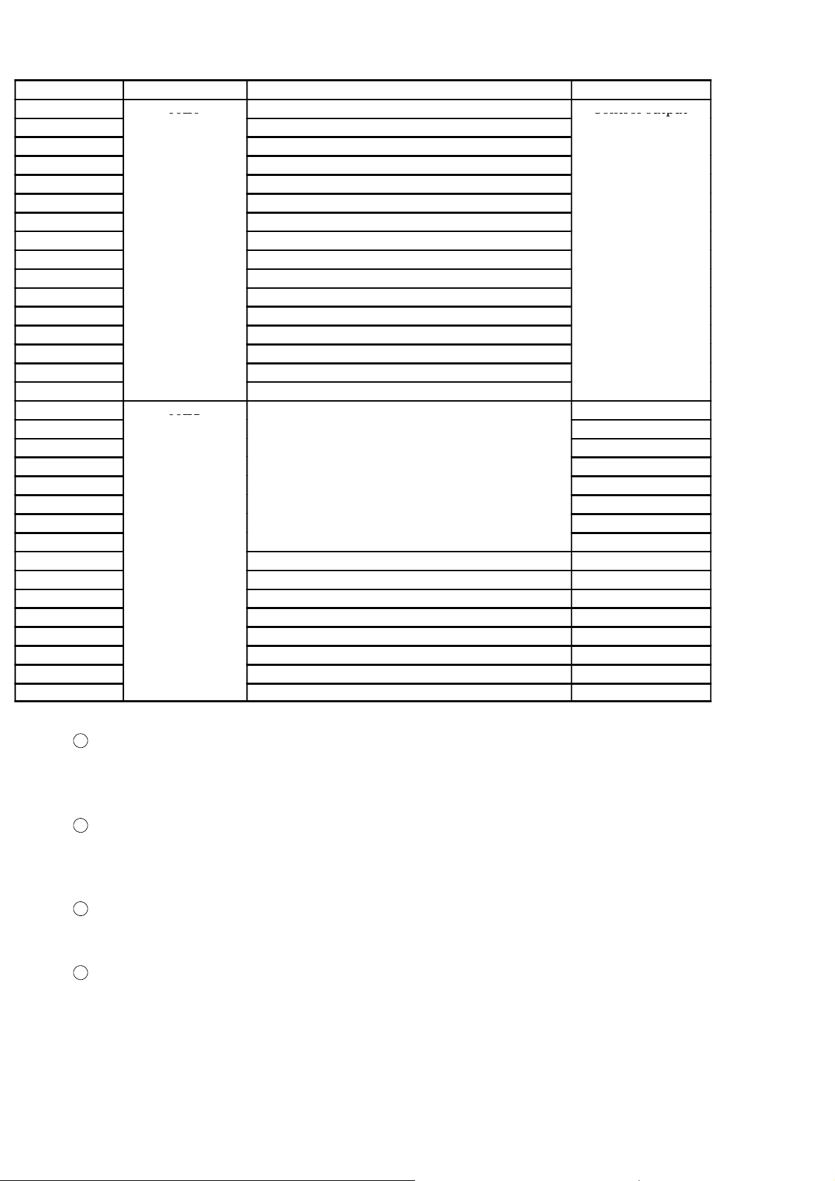
(2) Remote output(Master→Instrument) Occupies 4 stations
00E0
Communication
00E1
Control
output
00E2
00E7
y
Device NO.
RX0000
RX0001
RX0002
RX0003
RX0004
RX0005
RX0006
RX0007
RX0008
RX0009
RX000A
RX000B
RX000C
RX000D
RX000E
RX000F
RX0010
RX0011
RX0012
RX0013
RX0014
RX0015
RX0016
RX0017
RX0018
RX0019
RX001A
RX001B
RX001C
RX001D
RX001E
RX001F
RX0020
・
RX006F
RX0070
RX0071
RX0072
RX0073
RX0074
RX0075
RX0076
RX0077
RX0078
RX0079
RX007A
RX007B
RX007C
RX007D
RX007E
RX007F
Buffer address Contents Classification
00E0
00E1
①Setting value writing request (Response 1)
②General command response (Response 2)
③Writing/reading out selection response (R/W response)
④Operation mode changeover response(Response 3)
⑤CPU normal operation
⑥Decimal point position 1
⑥Decimal point position 2
⑥Decimal point position 4
⑦S0
⑦S1
⑦S2
⑧In the holding
⑨Abnormal load value
Communication
Control output
00E2
〜00E6
00E7
System reservation zone
⑩Initial data setting request flag
⑪Error reset request flag
⑫Remote ready
18
Page 24
Occupies 2 stations
00E0
Communication
00E1
Control
output
00E2
00E7
y
Device NO.
RX0000
RX0001
RX0002
RX0003
RX0004
RX0005
RX0006
RX0007
RX0008
RX0009
RX000A
RX000B
RX000C
RX000D
RX000E
RX000F
RX0010
RX0011
RX0012
RX0013
RX0014
RX0015
RX0016
RX0017
RX0018
RX0019
RX001A
RX001B
RX001C
RX001D
RX001E
RX001F
RX0020
・
・
RX006F
RX0030
RX0031
RX0032
RX0033
RX0034
RX0035
RX0036
RX0037
RX0038
RX0039
RX003A
RX003B
RX003C
RX003D
RX003E
RX003F
Buffer address Contents Classification
00E0
00E1
①Setting value writing request (Response 1)
②General command response (Response 2)
③Writing/reading out selection response (R/W response)
④Operation mode changeover response(Response 3)
⑤CPU normal operation
⑥Decimal point position 1
⑥Decimal point position 2
⑥Decimal point position 4
⑦S0
⑦S1
⑦S2
⑧In the holding
⑨Abnormal load value
Communication
Control output
00E2
00E7
System reservation zone
⑩Initial data setting request flag
⑪Error reset request flag
⑫Remote ready
19
Page 25
Occupies 1 station
00E0
Control
output
00E1
Device NO.
RX0000
RX0001
RX0002
RX0003
RX0004
RX0005
RX0006
RX0007
RX0008
RX0009
RX000A
RX000B
RX000C
RX000D
RX000E
RX000F
RX0010
RX0011
RX0012
RX0013
RX0014
RX0015
RX0016
RX0017
RX0018
RX0019
RX001A
RX001B
RX001C
RX001D
RX001E
RX001F
Buffer address Contents Classification
00E0
⑦S0
⑦S1
⑦S2
⑧In the holding
⑨Abnormal load value
Control output
00E1
⑩Initial data setting request flag
⑪Error reset request flag
⑫Remote ready
1
Setting value writing response (Response 1)
The end of writing by the set value writing request (request 1) is notified.
ON :In completion of writing
OFF :After confirming OFF of “Setting value writing request(Request 1)”
2
General command response (Response 2)
The end of the command instruction by the general command request (request 2) is notified.
ON :In the completion of command instruction
OFF :After confirming OFF of the general command request (Request 2)
3
Writing/Reading out selecting response (R/W response)
Notify the status of write/reading out by the command instruction when notifying by the
general command response (response 2).
4
Operating mode changeover response(Response 3)
Notify that the end of the operation mode changeover by the operation mode changeover
request (request 3(RY0004)).
ON :In the completion of the changeover
OFF :After confirming the OFF of the operation mode changeover request(Request 3)
20
Page 26

5
CPU normal operation
Notify that CC−LINK interface is operating normally. Reverse the status of ON/OFF in 0.5
seconds.
6
Decimal point position 1, 2, 3 or 4
Notify the decimal point position of the load value by the binary value of three points. This
output is updated by turning on the power supply, and initialed data set request flag (RY0079).
0 :No decimal point
0
2
3
4
digit
digit
digit
digit
7
S0〜S2
1 :10
2 :10
3 :10
4 :10
Notify the condition of S0〜S2. The same condition with S0〜S2 of the indicator
8
Holding
Notified whether the load value is holding.
ON :Holding
OFF :Free running
9
Abnormal load value
Notifies when the load value is “OL” or “−OL”.
ON :When abnormality occurs
OFF :Normal
10
Initialed data set completion flag
Notify the end of initialization when there is a request with initialed data set request flag
(RY0079).
ON :In the completion of set
OFF :Normal
11
Error condition flag
Notify when the error occurs in the indicator. After the error is released, it is reset with error
reset request flag (RY007A).
ON :In the occurrence of error
OFF :Normal
12
Remote ready
Notified to be able to complete initialization and to communicate.
ON :Possible to communicate
OFF :In the initialization
21
Page 27
6. Operation method
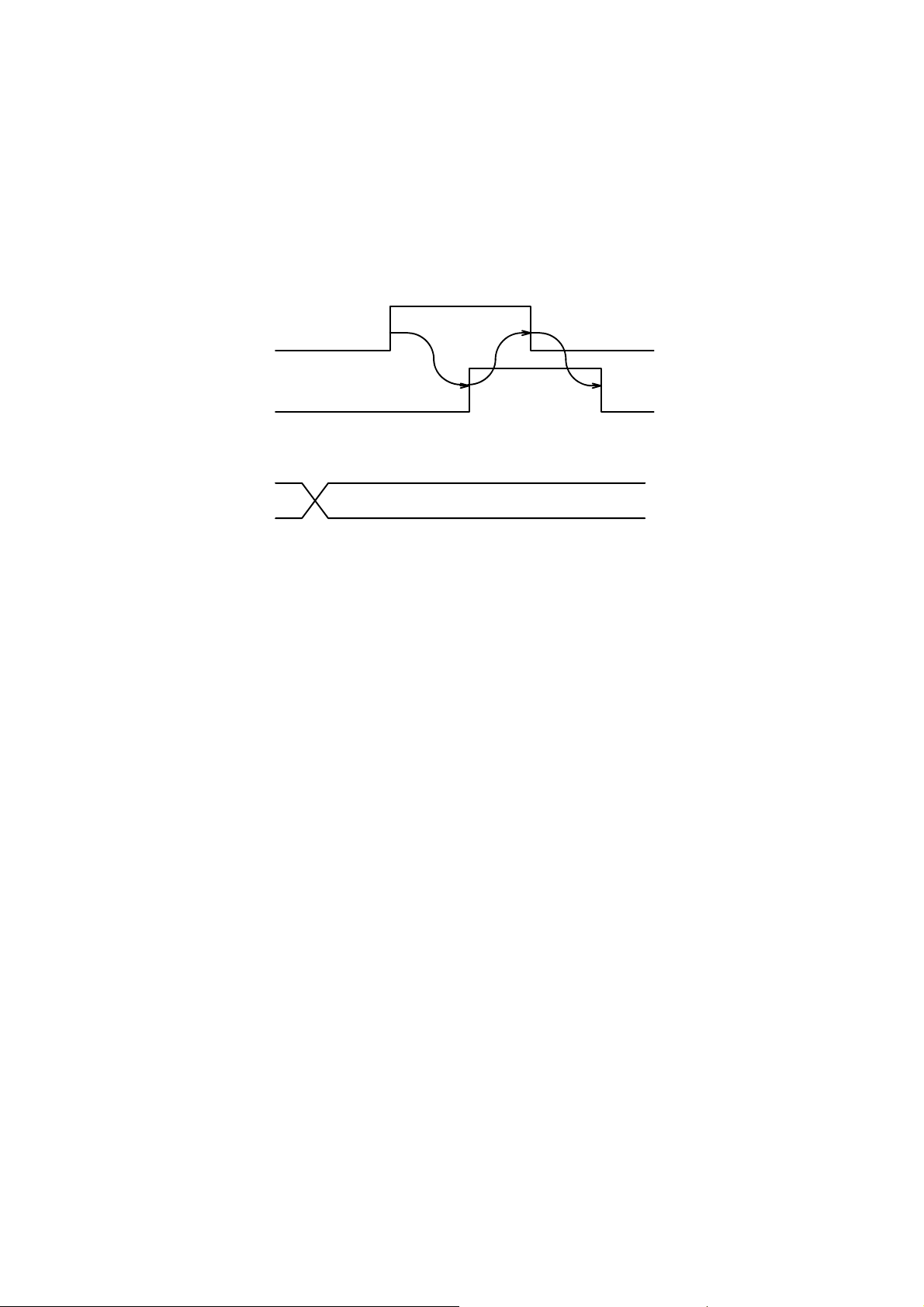
6−1. Writing the set value (Special data area)
The set value is set in the special data area.
The instrument recognizes that “Set writing request (request 1) RY0000” was turned on, and it
writes the data set in “Special data area (RW0000−RW0009)” into the indicator.
It responds to the master station by “Set value writing response RX0000 (response 1)” after
writing is completed.
Time chart
Set value writing request (Request 1)
(RY0000)
Set value writing response(Response 1)
(RX0000)
Special data
(RWw0000)
〜
(RWw0009)
22
Page 28

6−2. Writing/Reading by general command
Data is set in the general data area and command No. is set in the command No. area.
The instrument recognize that “General command request RY0002 (Request 2)”, and it execute to
write the data set in “General data area (RWr000C〜000D)” by “Selection of writing/reading out
(RY0003)” or “Command No.(RWw000E)”, or to reading the data into “General data area
(RWw000C〜000E)” to the instrument.
It responds to the master station by ”General command response RX0000 (response 2)” after
writing is completed.
1
Writing request
General command request (Request 1)
(RY0002)
General command response (Response 1)
(RX0000)
Selection of writing or reading
(RY0003)
General data
(RWw000C)
〜
(RWw000D)
Command NO.
(RWw000E)
Command No.(Response)
(RWr010E)
Selection response of writing or
reading out
(RX0003)
23
Page 29

2
Reading out request
General command request (Request 1)
(RY0002)
General command response (Response 1)
(RX0000)
Selection of writing or reading out
(RY0003)
Command No.
(RWw000E)
General data
(RWw000C)
〜
(RWw000D)
Command No.(Response)
(RWr010E)
Selection response of writing
or reading out
(RX0003)
24
Page 30

6−3. Shift to status where it is possible to communicate
“Remote READY (RX007B)” is turned on along with the power supply turning on after
initialization (set initialing) completion is done and it is assumed the status where it is possible to
communicate.
Moreover, remote READY is turned off when ”Set initial request (RY0079)” transmitted by the
master station is turned on, and initialization is executed. It responds to the master station after
initialization is completed by turning on ”Set initial response (RX0079)”.
That the master station recognizes turning on ”Set initial response (RX0079)”, and ”Set initial
response (RX0079)” is turned off makes that ”Set initial request (RY0079)” is turned off, and
remote ready is turned on.
Set initial request
(RY0079)
Set initial response
(RX0079)
Remote ready
(RX007B)
Power supply turning on
6−4. CPU normal operation signal
When the instrument operates normally, the condition of ”CPU normal operating signal
(RX0006)” is reversed at 0.5 seconds interval.
CPU normal operation
(RX0006)
0.5 s
25
Page 31
7. Specifications of interface
7−1. CC−Link interface spec
Specifications
Version of CC−LINK Ver.1.10
Occupied stations No.
Communication method Polling method
Synchronous method Bit synchronization method
Contents
Selectable from 1,2 or 4 stations.
Baud rate Selectable from 156 kbps, 625 kbps, 2.5 Mbps, 5 Mbps or 10 Mbps
Transmission path form RS.485 bus
Transmission format HDLC conforming
Remote station number In the case of 1 station occupied,Noʼs. 01 to 64 can be selectable.
Cable length Baud rate(bps) Total extensiondistance(m)
Numbers of connection In the case of 1 station occupied, 64 units at maximum.
Termination Resistance externally attached
Status LED The status of communication is expressed with four LED.RUN, SD, RD or ERR
In the case of 2 stations occupied,Noʼs. 01 to 63 can be selectable.
In the case of 4 stations occupied,Noʼs. 01 to 61 can be selectable.
156 kbps 1 200m or less
625 kbps 600m or less
2.5 Mbps 200m or less
5 Mbps 150m or less
10 Mbps 100m or less
In the case of 2 stations occupied, 32 units at maximum.
In the case of 4 stations occupied, 16 units at maximum.
7−2. Accessory
Instruction manual or CC−LINK 1 piece
Connector pin configuration for
CC−LINK
1 piece attached(721−105/037−000 WAGO)
26
Page 32

D The contents of this manual may subject to change without notice.
HEAD QUARTER : MINEBEA CO., LTD.
4106−73 Miyota, Miyota−machi, Kitasakugun, Nagano−ken 389−0293, Japan
0267−32−2200 .0267−31−1350
Measuring Components Business Unit
FUJISAWA PLANT 1−1−1, Katase, Fujisawa−shi Kanagawa−ken, 251−8531 Japan
0466−22−7151 .0466−22−1701
KARUIZAWA PLANT 4106−73 Miyota, Miyota−machi, Kitasakugun, Nagano−ken 389−0293, Japan
0267−31−1309 .0267−31−1350
HOMEPAGE ADDRESS http://www.minebea−mcd.com
 Loading...