

Page 1

Artisan Technology Group is your source for quality
new and certied-used/pre-owned equipment
• FAST SHIPPING AND
DELIVERY
• TENS OF THOUSANDS OF
IN-STOCK ITEMS
• EQUIPMENT DEMOS
• HUNDREDS OF
MANUFACTURERS
SUPPORTED
• LEASING/MONTHLY
RENTALS
• ITAR CERTIFIED
SECURE ASSET SOLUTIONS
SERVICE CENTER REPAIRS
Experienced engineers and technicians on staff
at our full-service, in-house repair center
Instra
Remotely inspect equipment before purchasing with
our interactive website at www.instraview.com
Contact us: (888) 88-SOURCE | sales@artisantg.com | www.artisantg.com
SM
REMOTE INSPECTION
View
WE BUY USED EQUIPMENT
Sell your excess, underutilized, and idle used equipment
We also offer credit for buy-backs and trade-ins
www.artisantg.com/WeBuyEquipment
LOOKING FOR MORE INFORMATION?
Visit us on the web at www.artisantg.com for more
information on price quotations, drivers, technical
specications, manuals, and documentation
Page 2
INSTRUCTION MANUAL
FOR
CSD-801 DIGITAL INDICATOR
MINEBEA CO., LTD.
SHINKOH COMMUNICATION DIVISION
DRW.NO. 294-1011-A
Artisan Technology Group - Quality Instrumentation ... Guaranteed | (888) 88-SOURCE | www.artisantg.com
Page 3

Artisan Technology Group - Quality Instrumentation ... Guaranteed | (888) 88-SOURCE | www.artisantg.com
Page 4
§1.
OUTLINE
CONTENTS
CSD-801 DIGITAL INDICATOR
Page
1
§2.
§3.
§4.
§5.
§6.
FEATURES
NAME OF EACH PART
3-1 Front panel
3-2
Rear panel 3
INSTALLATION
CONNECTION METHOD 5
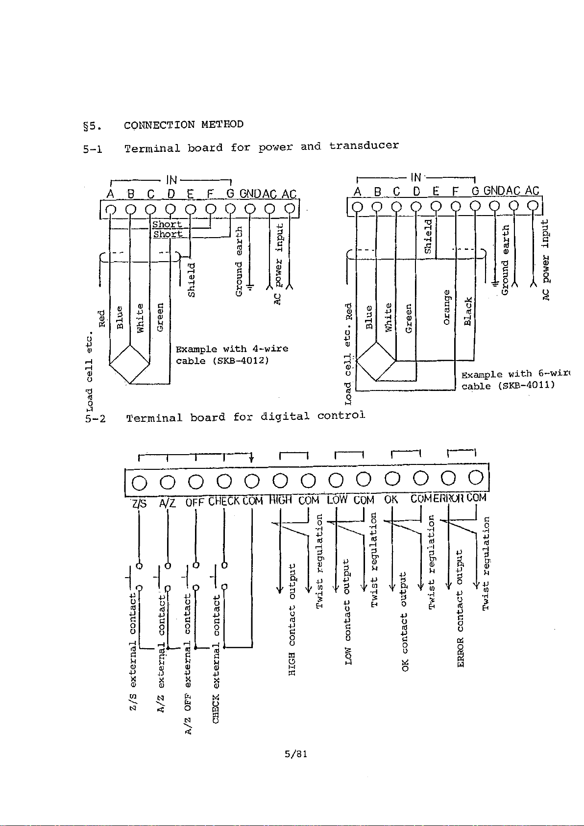
5-1
5-2
Terminal board for power and transducer
Terminal board for digital control 5
5-3 BCD-OUT connector 6
5-4 Precautions for connection 8
HANDLING PROCEDURE
10
6-1 Connection 11
6-2 Power ON
11
1
2
2
4
5
6-3
6-4
Actual load calibration-I 12
Actual load calibration-II
6-5 Actual load calibration-III
6-6
Electric calibration-I
6-7 Electric calibration-II 20
6-8 Registration of each function by SET MODE 21
6-9 Start of measurement 21
Artisan Technology Group - Quality Instrumentation ... Guaranteed | (888) 88-SOURCE | www.artisantg.com
16
17
19
Page 5
§7. FUNCTION IN MEASUREMENT MODE 22
7-1 Zero set function 22
7-2 AUTO ZERO, AUTO ZERO OFF function 23
7-3 Comparative setting function (Comparator) 25
7-4 CENTER ZERO function 27
§8. FUNCTION BY SET MODE (INITIAL SETTING FUNCTION) 28
8-i Required switch for SET MODE 29
8-2 ZERO TRACKING 30
8-3 Minimum effective digit setting function 34
8-4 Multiplication function 38
8-5 Pre-set cancellation function 40
8-6 Comparative setting condition
changeover function 43
8-7 Judgment function 46
8-8 Dummy 0 indication 49
8-9 Decimal point indication 51
8-10. Sign inversion function 53
8-11 Sign transfer function 55
8-12 BCD-OUT true conversion 57
8-13 Unit indication changeover 58
8-14 Manual Z/S function 59
8-15 Back-up Data Clear 60
§9. SELF-CHECK FUNCTION 61
§10. ERROR INDICATION 61
§11. SET MODE SETTING VALUE TABLE 65
Artisan Technology Group - Quality Instrumentation ... Guaranteed | (888) 88-SOURCE | www.artisantg.com
Page 6
§12. ANALOG ADJUSTMENT 67
§13.
12-1
12-2
12-3
12-4
12-5
12-6
SPECIFICATION
13-1
13-2
Standard parts adjustment
Layout of adjustment parts 68
Adjustment of bridge voltage 69
GAIN adjustment
Change of CHECK value
Change of TARE cancel value
General specification 75
Block Diagram
13-3 Appearance Drawing
§14. ACCESSORIES
67
69
71
73
75
78
80
81
Artisan Technology Group - Quality Instrumentation ... Guaranteed | (888) 88-SOURCE | www.artisantg.com
Page 7

Artisan Technology Group - Quality Instrumentation ... Guaranteed | (888) 88-SOURCE | www.artisantg.com
Page 8
§1. OUTLINE
The equipment is CPU mounted digital indicator for
instrumentation.
§2. FEATURES
o Remote setting function is provided to the converter
(transducer) power, and the error from cable length
will be cancelled.
o Flying capacitor is adopted at signal amplifier input
step. In common mode noise reduction ratio is set at
120dB.
o Drift at the signal amplifier is reduced as much as
possible by chopper amplifier.
o Maximum indication is 9999, with multi (multiplying)
function and, at dumy (-)0, indication up to (+)199980
is possible.
o Provided with BCD parallel-out output (open collector),
which can simultaneously output the total load and
net load.
o Setter is provided with 5-digits 2-steps digital switch,
as well as pre-set cancellation and judgment functions.
It can also be connected to MINEBEA digital setter
CSD-551B by using BCD parallel out connector.
o By its zero tracking function, secular change in zero-
point of the converter and the like will be cancelled.
1/81
Artisan Technology Group - Quality Instrumentation ... Guaranteed | (888) 88-SOURCE | www.artisantg.com
Page 9
§ 3 -
3 -I Front panel
NAME OF EACH PART
M--sao 11 G;51 Ital IF meettnlO
C i
IIii
9
• WO I117 tali 0 rt 41
11
woo
fillrillini
0 CO igi IN Li
mum
1E1111
11
,
L'o
A*2
"I r0e I
0s
o�sEi
voce
lArE ZERO GAIN SPAN C/S
9 1F 35? , NINTH
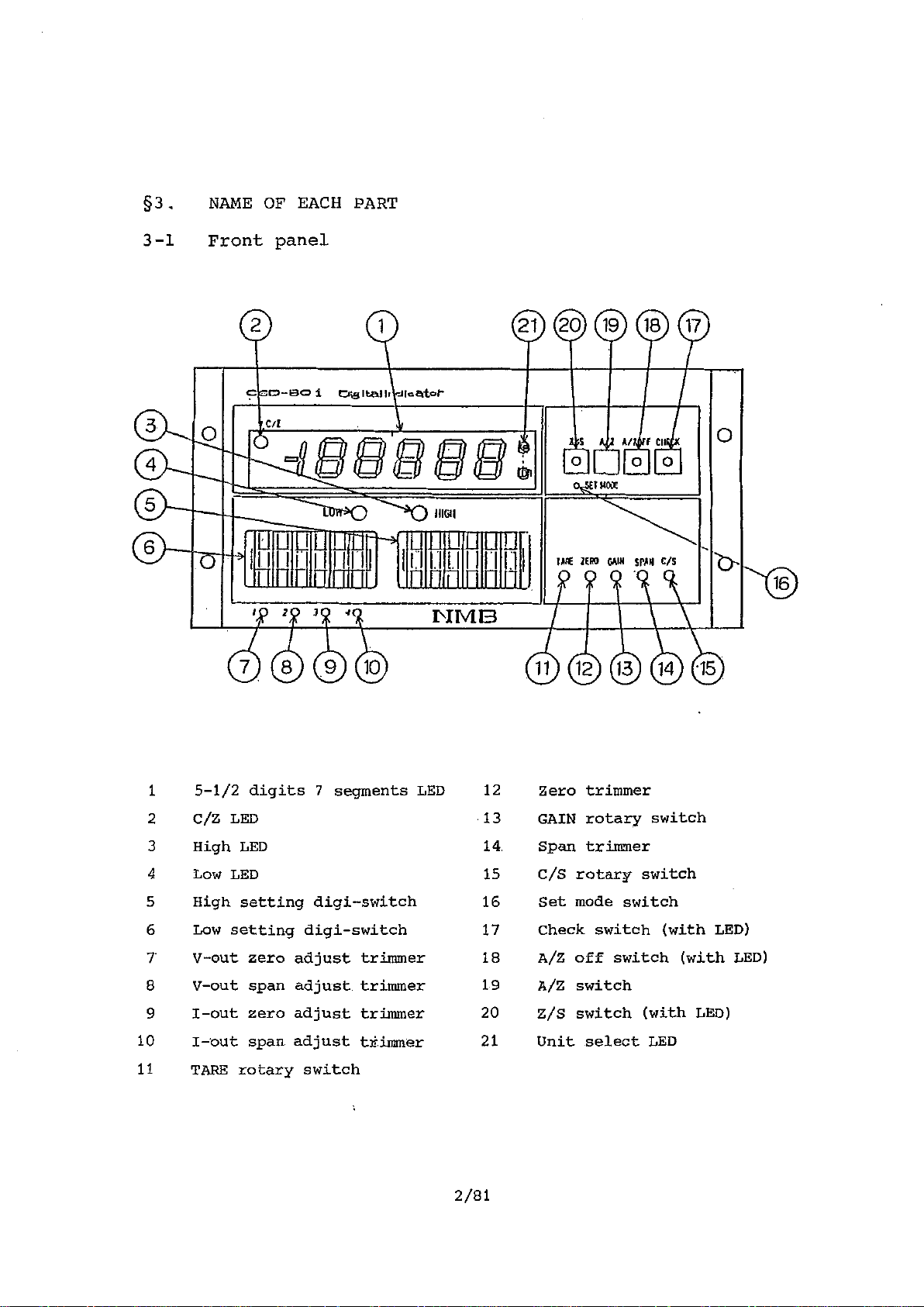
1 5-1/2 digits 7 segments LED 12 Zero trimmer
2 C/Z LED
3 High LED
4
Low LED 15
5
High setting digi-switch
13
14
16 Set mode switch
GAIN rotary switch
Span trimmer
C/S rotary switch
]
6
Low setting digi-switch
7' V-out zero adjust trimmer
8 V-out span adjust trimmer 19 A/Z switch
9
I -out zero adjust trimmer
10
11 TA RE rotary switch
I -out span adjust trimmer
Artisan Technology Group - Quality Instrumentation ... Guaranteed | (888) 88-SOURCE | www.artisantg.com
17
18
20 Z/S switch (with LED)
21
2/81
Check switch (with LED)
A/Z off switch (with LED)
Unit select LED
Page 10
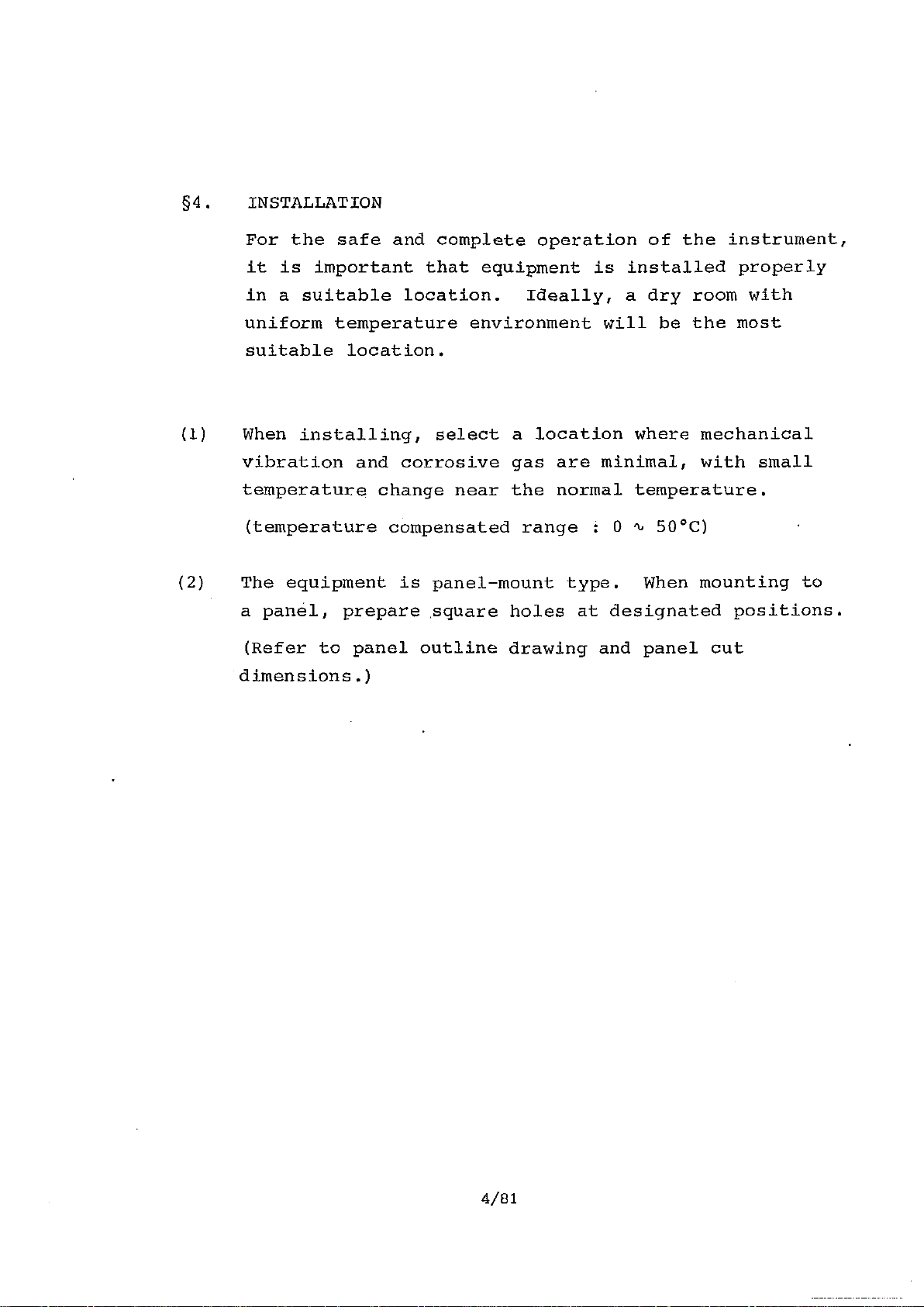
§4. INSTALLATION
For the safe and complete operation of the instrument,
it is important that equipment is installed properly
in a suitable location. Ideally, a dry room with
uniform temperature environment will be the most
suitable location.
(1) When installing, select a location where mechanical
vibration and corrosive gas are minimal, with small
temperature change near the normal temperature.
(temperature compensated range i 0 % 50°C)
(2) The equipment is panel-mount type. When mounting to
a panel, prepare square holes at designated positions.
(Refer to panel outline drawing and panel cut
dimensions.)
4/81
Artisan Technology Group - Quality Instrumentation ... Guaranteed | (888) 88-SOURCE | www.artisantg.com
Page 11
Z/S external contact--
I 0
A/2 external contact —I
A/Z OFF external contact --1-- C
CHECK external
HIGH contact output
contact ----
-0 0
Twist regulation --
LOW contact output //
0 -Zt
0 0--
<
r-
Cil
IN
11
A
11-0
0
0
0
-r-
rn
0
7t
0
0
0
7- 0
0 n
ulLoad cell etc.
Red
Blue
1-3
White
5
H.
o
tr
0
ct
0
0
h Load cell etc. Red
K
0
(r, tcs
1--•
IQ
Green
•
I
Shield
Ground earth
II
AC power input
Twist regulation -71:0
OK contact output
Twist
ERROR contact output
Twist regulation X
regulation rrIM
0
0
O
0
AC power input
Artisan Technology Group - Quality Instrumentation ... Guaranteed | (888) 88-SOURCE | www.artisantg.com
Page 12
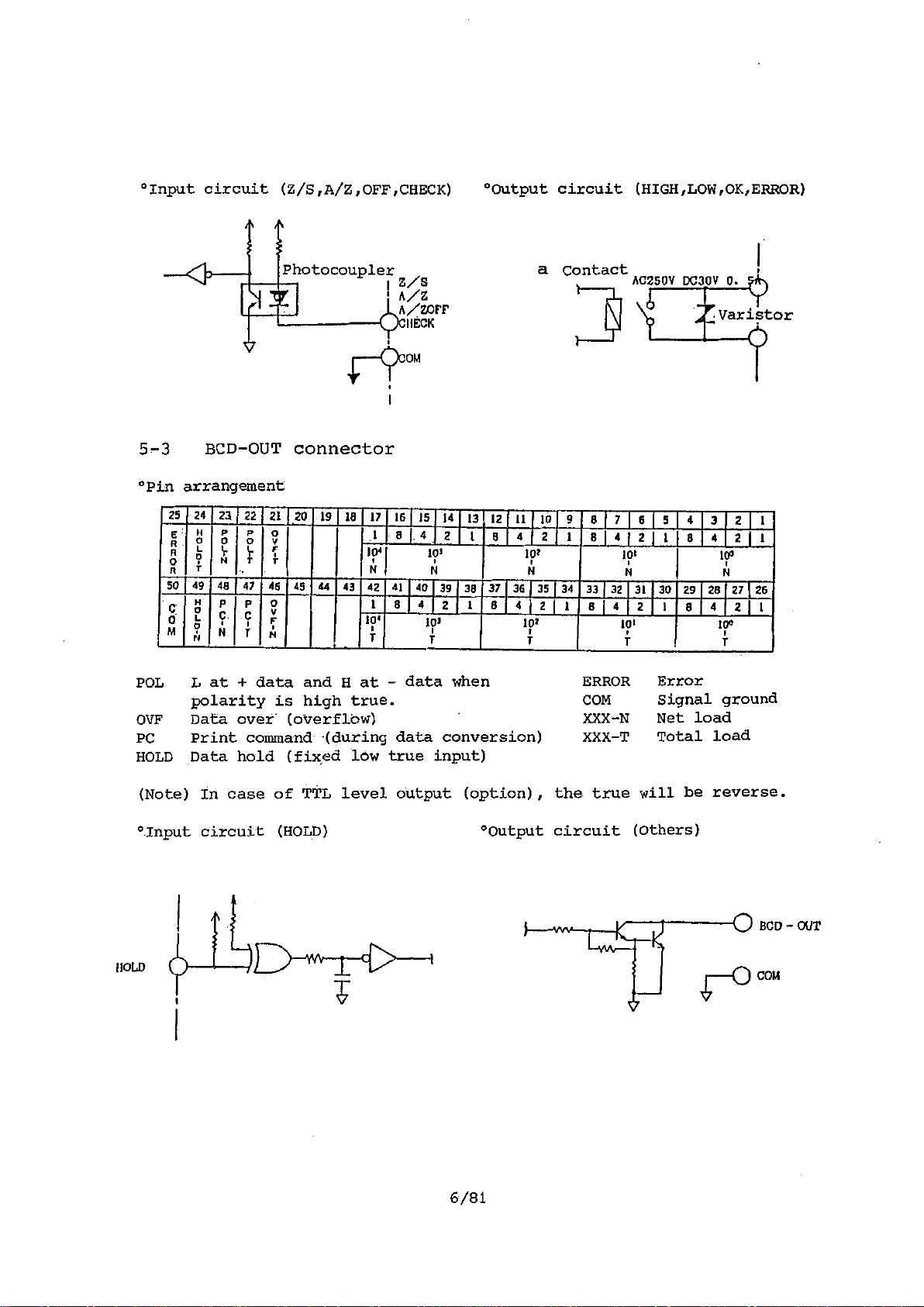
°Input circuit (Z/S,A/Z,OFF,CHECK)
°Output circuit (HIGH,LOW,OK,ERROR)
Photocoupler
z/s
a Contact
n/z
A/'7,10fF
IIECK
OM
5-3 BCD-OUT connector
°Pin arrangement
25 24 23
HP
Roev
o
ton
4r‘,"4
ft
r
50 49 48
o H
C
0
I.
M
.
N
POL
L at + data and H at - data when
polarity is high true.
OVF Data over (overflow) XXX-N
PC
Print command -(during data conversion) XXX-T
HOLD Data hold (fixed low true input)
221 21120
47
p
C
C
N
P
0
I
T
46 49 44
0
P
v
f
T 1
N
19 1 18 [17 16 15
1
8 1.4
1041 103
14 1 N
43
42 41
10'
i
- 4
40
I
8
4
101
T
39
14
2
2
38
13
1
1
12 11
8
37
36) 35 1 34
8
10
4 2
103
N
4 1 2 1 1
101
i
9 8 [
1
81 4 1 2 1 1
33 1 32
8 1
ERROR
COM
7 16
4 2 1 8
AC250V DC30V 0.
1 5 4
101
N
31
10'
f
8 4 2 1
30 29 28 27 1
Error
Signal ground
Net load
Total load
Naristor
3 2 1 1
1
100
N
26
4 2 1
10°
T
1
(Note) In case of TTL level output (option),
the true will be reverse.
°.Input circuit (HOLD) °Output circuit (Others)
HOLD
6/81
BCD — OUT
COM
Artisan Technology Group - Quality Instrumentation ... Guaranteed | (888) 88-SOURCE | www.artisantg.com
Page 13

Timing Chart (When data command is high true output)
°Normal
0,2mS
270m8
DATA
ML
P. C.
°Hold signal input
HOLD
DATA
POL
P. C.
°Data over (overflow)
DATA
POL
60••••••••=.•••
ML
L
H
P. C.
O. V. F.
DATA
POL
P. C.
4RMDR
°Error
7/81
Artisan Technology Group - Quality Instrumentation ... Guaranteed | (888) 88-SOURCE | www.artisantg.com
Page 14
5-4 Precautions for connection
(1) Wiring of sensor input (A, B, C, D, E, F, G)
For connection, use MINEBEA shild cable SKB-4012
(4-wires) or SKB-4011(6-wires). When using 6-wires
cable, maximum length of the cable should be up to
200m.
It is essential that this wiring is separated from
the wirings for power circuit and for control contact
output circuit. In any case, it must not be placed
near a cable with big current flow such as power
cable. Therefore, in case of conduit wiring,
a separate conduit from that of power circuit and
control contact output circuit should be used.
(2) Wiring of "Out" circuit (V-Out, I-Out)
Use 2-core shilding wire. The load shall be more
than 2 k0 at V-Out and less than 500 0 at I-Out
(option). Wiring should be as short as possible,
and as in (1) above, should be wired away from power
cable. or the like.
(3) Wiring of control signal input circuit (Z/S, A/Z, OFF,
CHECK)
In order to avoid the reception of external noise,
the input circuit is received internally at the
photocoupler, but the wiring should be short and
should be away from power cable or the like.
8/81
Artisan Technology Group - Quality Instrumentation ... Guaranteed | (888) 88-SOURCE | www.artisantg.com
Page 15
(4) Wiring of control contact output circuit (HIGH, LOW,
OK, ERROR)
Wiring cable should be determined according to the
applied voltage, current and so forth. Normally,
the cable does not require shielding.
(5) Wiring of GND (earth) circuit
GND terminal is linked with the amplifier body.
From this terminal, pull out the earth wire and,
preferably solder to copper plate or copper rod and
bury in wet ground.
Please note that GND terminal and analog common
(V-Out-terminal etc.) are not common, so make sure
it will not short-circuit.
(6) Wiring of power circuit
"AC" terminal is a connecting terminal for alternate
current power circuit.
"AC" voltage is standard "100V", but if the equipment
is manufactured in specification other than "100V"
according to the customer's requirements, such voltage
value will be entered. Therefore, make sure that the
designated voltage is supplied at all times.
If the voltage supplied is below the rating, the
instrument will not operate, or if operated, its
performance cannot be guaranteed. If excessive
voltage is supplied, the fuse will cause the breaking
of wire, or, there is a danger of internal power
transformer being burned.
9/81
Artisan Technology Group - Quality Instrumentation ... Guaranteed | (888) 88-SOURCE | www.artisantg.com
Page 16

HANDLING PROCEDURE
§6.
In order to utilize the various functions of CSD-801 effectively, adjustments shall be made
according to the following procedure.
In case of changing our standard adjusted product
to the customer's specification or changing the
specification of previously adjusted product.
Using digital output only
6-1
(Connection)
6 -2
(Power on)
6-3
(Actual load
calibration I)
4,
Combined use of
analog output
Basically, adjustment
in our factory will be
required.
Please contact our
sales representative.
In case the product has been shipped from
our factory, with adjustment required by
the customer's specification already completed.
Using digital output
only
6-1
(Connection)
6-2
(Power on)
6-4 6-6
(Actual load
calibration II•
Electric
calibration I)
6 -B
(Function' registration`
by set mode)
6 -9
(Start measurement)
6-8
(Function registration
by set mode)
4.
6-9
(Start measurement)
Artisan Technology Group - Quality Instrumentation ... Guaranteed | (888) 88-SOURCE | www.artisantg.com
Page 17
6-1 Connection
Connect the transducer and the body (CSD-801) according
to Section 5.
When using 4-wires cable (equivalent to our SKB-4012)
for wiring the equipment to the transducer, use the
attached short cable (one each of red and white) and
shorten between A-F and C-G of the terminal board for
transducer, located on the back panel of the equipment.
6-2 Power ON
Check the voltage and current and supply the power.
(standard AC100V)
Confirm the self-diagnosis indication by the equipment.
The indications are as follows.
1) E- 0 :Internal memory will be checked. If there is
an error, a number will be indicated in the ❑ .
(For details, refer to Section 10.)
2) 0. 0 :Shows the version of the program. In case of
malfunction, inform this number.
3) :Indications will increment from the right end,
and finally all LED will flash.
4) :With the completion of the above, measuring
mode will start.
Also confirm that the condition of each LED
on the front panel are
Indication data
Lz/s
[A/z OFF.
'CHECK
LED
LED ON
LED OFF
as follows.
XXXX (some value)
OFF
Artisan Technology Group - Quality Instrumentation ... Guaranteed | (888) 88-SOURCE | www.artisantg.com
Page 18
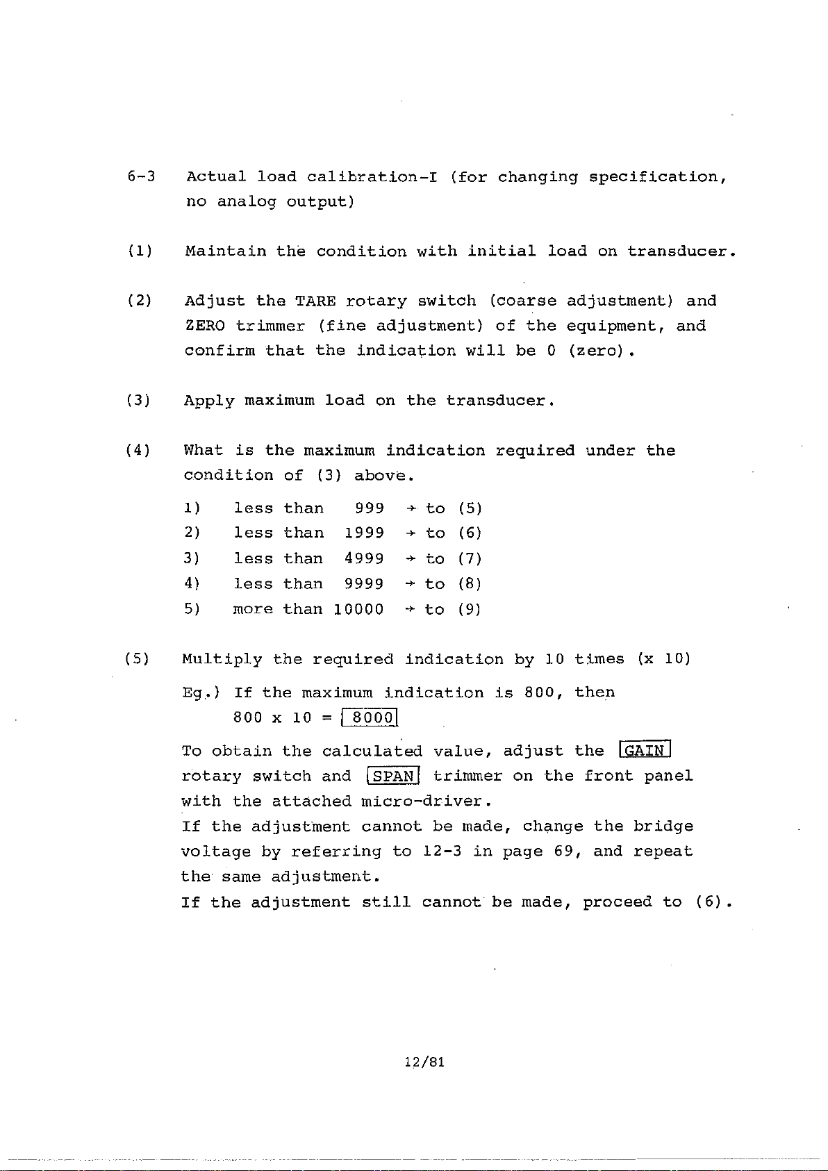
6-3 Actual load calibration-I (for changing specification,
no analog output)
(1) Maintain the condition with initial load on transducer.
(2) Adjust the TARE rotary switch (coarse adjustment) and
ZERO trimmer (fine adjustment) of the equipment, and
confirm that the indication will be 0 (zero).
(3) Apply maximum load on the transducer.
(4) What is the maximum indication required under the
condition of (3) above.
1) less than 999 4- to (5)
2) less than 1999 to (6)
3) less than 4999 to (7)
4) less than 9999 4- to (8)
5) more than 10000 to (9)
(5) Multiply the required indication by 10 times (x 10)
Eg,) If the maximum indication is 800, then
800 x 10 = P1500I
To obtain the calculated value, adjust the
'GAIN'
rotary switch and ISPANI trimmer on the front panel
with the attached micro-driver.
If the adjustment cannot be made, change the bridge
voltage by referring to 12-3 in page 69, and repeat
the same adjustment.
If the adjustment still cannot be made, proceed to (6).
12/81
Artisan Technology Group - Quality Instrumentation ... Guaranteed | (888) 88-SOURCE | www.artisantg.com
Page 19
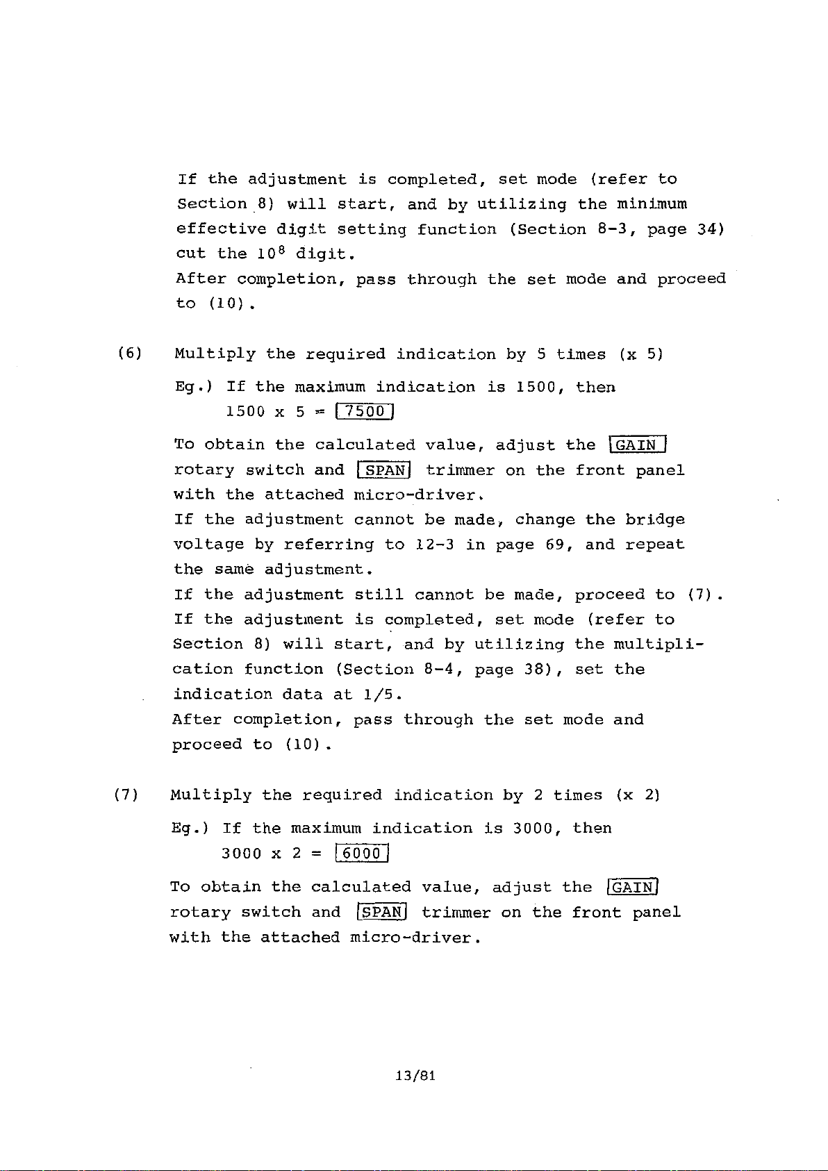
If the adjustment is completed, set mode (refer to
Section 8) will start, and by utilizing the minimum
effective digit setting function (Section 8-3, page 34)
cut the 108 digit.
After completion, pass through the set mode and proceed
to (10).
(6) Multiply the required indication by 5 times (x 5)
Eg.) If the maximum indication is 1500, then
1500 x 5 = 1 7500 1
To obtain the calculated value, adjust the IGAIN1
rotary switch and SPAN trimmer on the front panel
with the attached micro-driver.
If the adjustment cannot be made, change the bridge
voltage by referring to 12-3 in page 69, and repeat
the same adjustment.
If the adjustment still cannot be made, proceed to (7).
If the adjustment is completed, set mode (refer to
Section 8) will start, and by utilizing the multipli-
cation function (Section 8-4, page 38), set the
indication data at 1/5.
After completion, pass through the set mode and
proceed to (10).
(7) Multiply the required indication by 2 times (x 2)
Eg.) If the maximum indication is 3000, then
3000 x 2 = 60001
To obtain the calculated value, adjust the
rotary switch and
(SPAN
trimmer on the front panel
!GAIN]
with the attached micro-driver.
13/81
Artisan Technology Group - Quality Instrumentation ... Guaranteed | (888) 88-SOURCE | www.artisantg.com
Page 20
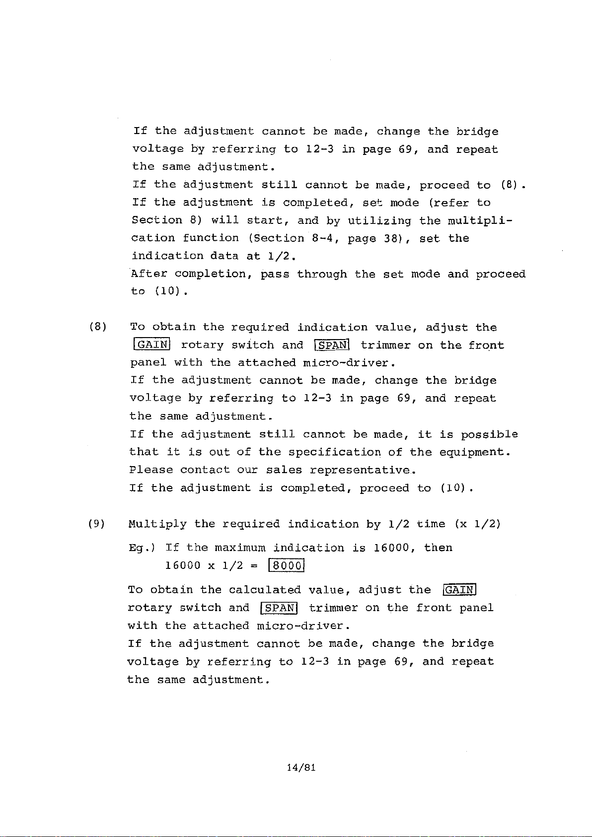
If the adjustment cannot be made, change the bridge
voltage by referring to 12-3 in page 69, and repeat
the same adjustment.
If the adjustment still cannot be made, proceed to (8).
If the adjustment is completed, set mode (refer to
Section 8) will start, and by utilizing the multipli-
cation function (Section 8-4, page 38), set the
indication data at 1/2.
After completion, pass through the set mode and proceed
to (10).
(8) To obtain the required indication value, adjust the
GAIN
rotary switch and SPAN trimmer on the front
panel with the attached micro-driver.
If the adjustment cannot be made, change
voltage by referring to 12-3 in page 69,
the bridge
and repeat
the same adjustment.
If the adjustment still cannot be made, it
that it is out of the specification of the
is possible
equipment.
Please contact our sales representative.
If the adjustment is completed, proceed to
(10) .
(9) Multiply the required indication by 1/2 time (x 1/2)
Eg.) If the maximum indication is 16000, then
16000 x 1/2 =
To obtain the calculated value, adjust the
8000
GAIN
rotary switch and (SPAN trimmer on the front panel
with the attached micro-driver.
If the adjustment cannot be made, change the bridge
voltage by referring to 12-3 in page 69, and repeat
the same adjustment.
14/81
Artisan Technology Group - Quality Instrumentation ... Guaranteed | (888) 88-SOURCE | www.artisantg.com
Page 21
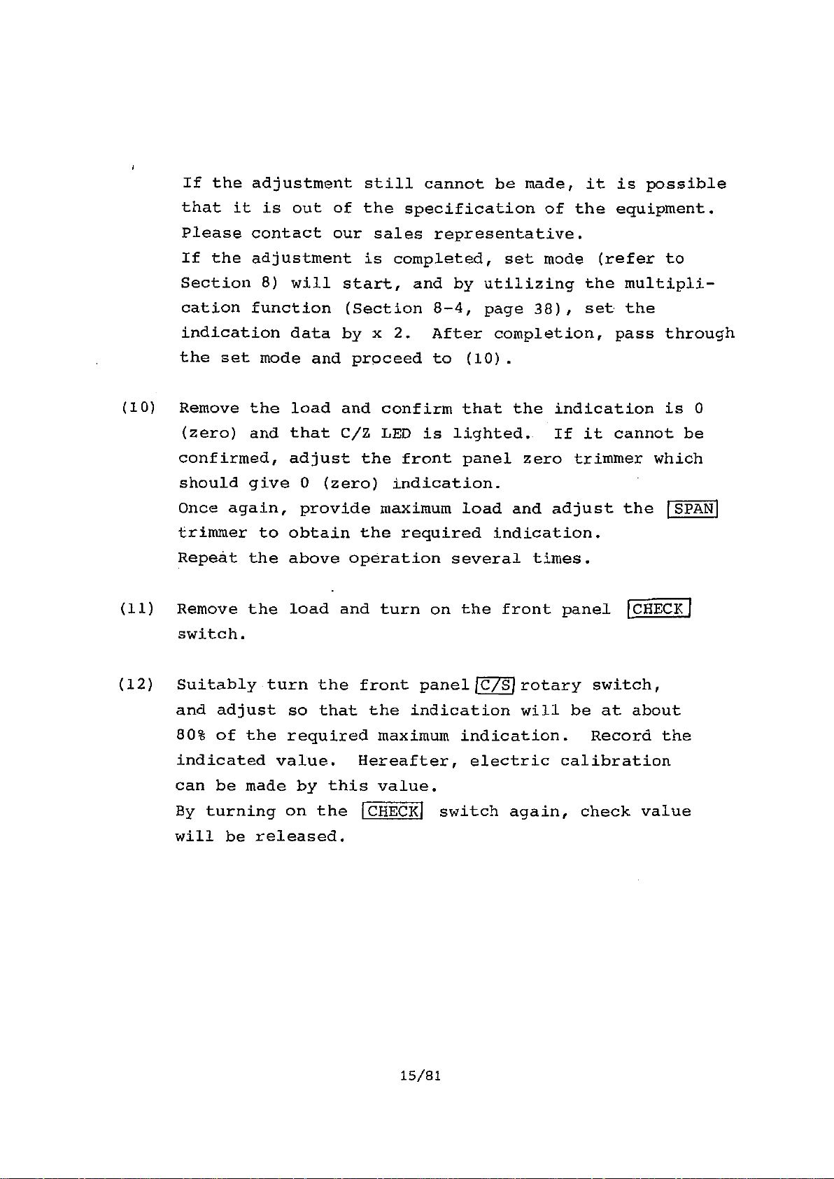
If the adjustment still cannot be made, it is possible
that it is out of the specification of the equipment.
Please contact our sales representative.
If the adjustment is completed, set mode (refer to
Section 8) will start, and by utilizing the multipli-
cation function (Section 8-4, page 38), set the
indication data by x 2. After completion, pass through
the set mode and proceed to (10).
(10) Remove the load and confirm that the indication is 0
(zero) and that C/Z LED is lighted. If it cannot be
confirmed, adjust the front panel zero trimmer which
should give 0 (zero) indication.
Once again, provide maximum load and adjust the
trimmer to obtain the required indication.
Repeat the above operation several times.
(11) Remove the load and turn on the front panel
CHECK I
switch.
(12) Suitably turn the front panel rotary switch,
and adjust so that the indication will be at about
80% of the required maximum indication. Record the
indicated value. Hereafter, electric calibration
can be made by this value.
By turning on the CHECK switch again, check value
will be released.
SPAN)
15/81
Artisan Technology Group - Quality Instrumentation ... Guaranteed | (888) 88-SOURCE | www.artisantg.com
Page 22
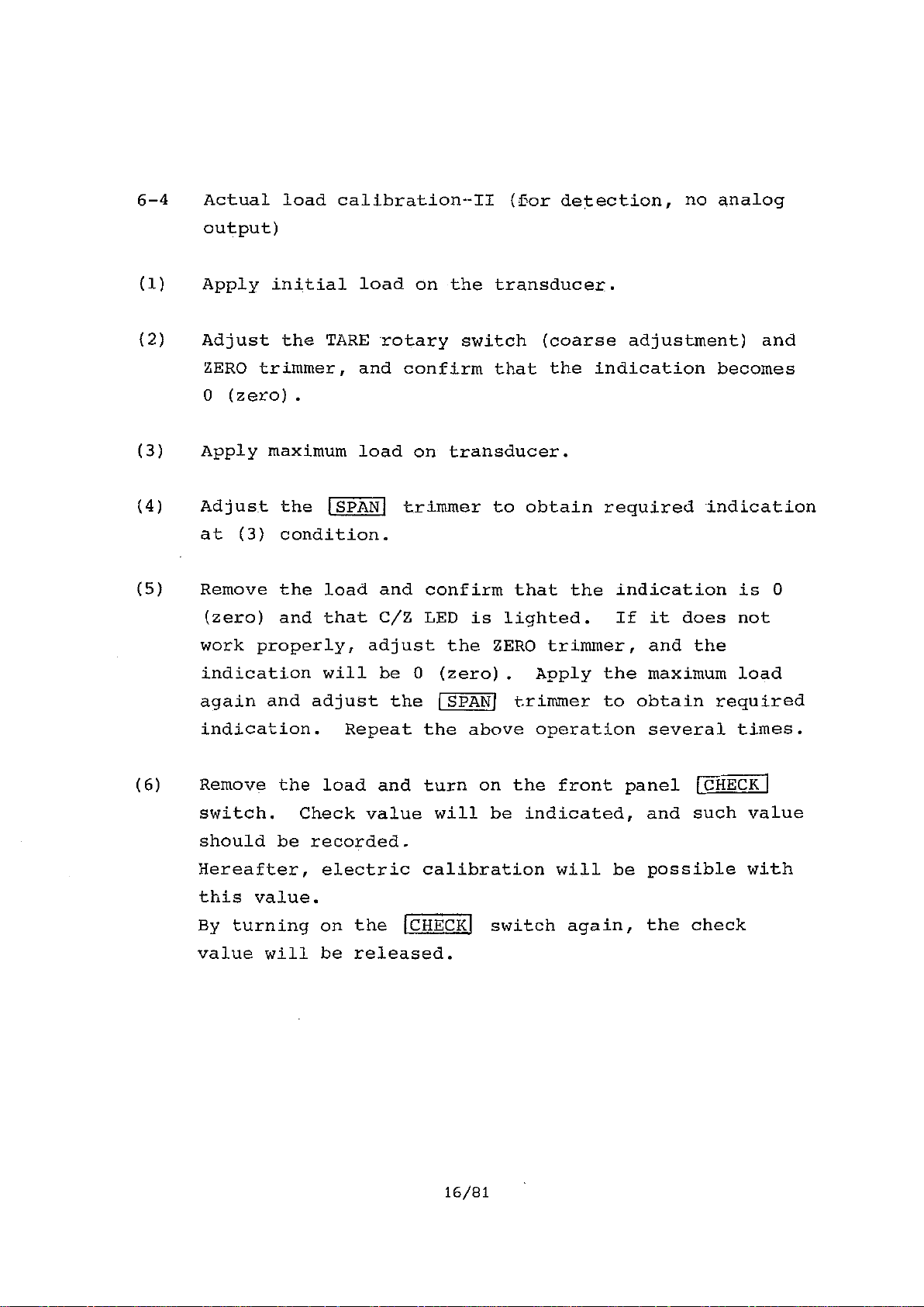
6-4 Actual load calibration•-II (for detection, no analog
output)
(1)
(2)
Apply initial load on the transducer.
Adjust the TARE rotary switch (coarse adjustment) and
ZERO trimmer, and confirm that the indication becomes
0 (zero).
(3)
(4) Adjust the
Apply maximum load on transducer.
,SPAN
trimmer to obtain required indication
at (3) condition.
(5) Remove the load and confirm that the indication is 0
(zero) and that C/Z LED is lighted. If it does not
work properly, adjust the ZERO trimmer, and the
indication will be 0 (zero). Apply the maximum load
again and adjust the SPAN] trimmer to obtain required
indication. Repeat the above operation several times.
(6) Remove the load and turn on the front panel (CHECK
switch. Check value will be indicated, and such value
should be recorded.
Hereafter, electric calibration will be possible with
this value.
By turning on the !CHECK switch again, the check
value will be released.
16/81
Artisan Technology Group - Quality Instrumentation ... Guaranteed | (888) 88-SOURCE | www.artisantg.com
Page 23
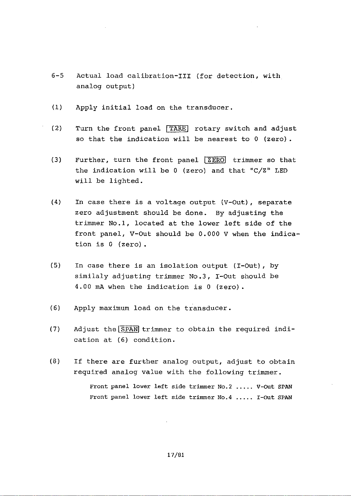
6-5 Actual load calibration-III (for detection, with
analog output)
(1) Apply initial load on the transducer.
(2) Turn the front panel TARE rotary switch and adjust
so that the indication will be nearest to 0 (zero).
(3) Further, turn the front panel jZEROJ trimmer so that
the indication will be 0 (zero) and that "C/Z" LED
will be lighted.
(4) In case there is a voltage output (V-Out), separate
zero adjustment should be done. By adjusting the
trimmer No.1, located at the lower left side of the
front panel, V-Out should be 0.000 V when the indica-
tion is 0 (zero).
(5) In case there is an isolation output (I-Out), by
similaly adjusting trimmer No.3, I-Out should be
4.00 mA when the indication is 0 (zero).
(6) Apply maximum load on the transducer.
(7) Adjust the[SPANjtrimmer to obtain the required indi-
cation at (6) condition.
(8) If there are further analog output, adjust to obtain
required analog value with the following trimmer.
Front panel lower left side trimmer No.2 V-Out SPAN
Front panel lower left side trimmer No.4 I-Out SPAN
17/81
Artisan Technology Group - Quality Instrumentation ... Guaranteed | (888) 88-SOURCE | www.artisantg.com
Page 24
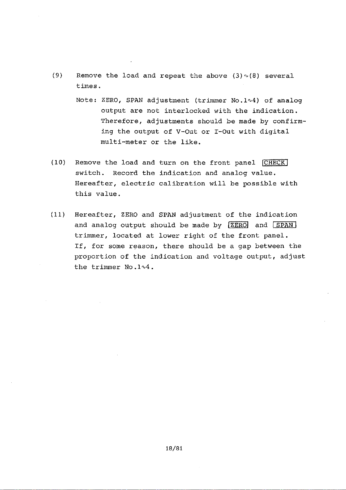
(9) Remove the load and repeat the above (3)q,(8) several
times.
Note: ZERO, SPAN adjustment (trimmer No.liA) of analog
output are not interlocked with the indication.
Therefore, adjustments should be made by confirm-
ing the output of V-Out or I-Out with digital
multi-meter or the like.
(10) Remove the load and turn on the front panel
switch. Record the indication and analog value.
Hereafter, electric calibration will be possible with
this value.
(11) Hereafter, ZERO and SPAN adjustment of the indication
and analog output should be made by IZEROI and
trimmer, located at lower right of the front panel.
If, for some reason, there should be a gap between the
proportion of the indication and voltage output, adjust
the trimmer No.1"4.
ICHECKI
SPAN I
18/81
Artisan Technology Group - Quality Instrumentation ... Guaranteed | (888) 88-SOURCE | www.artisantg.com
Page 25
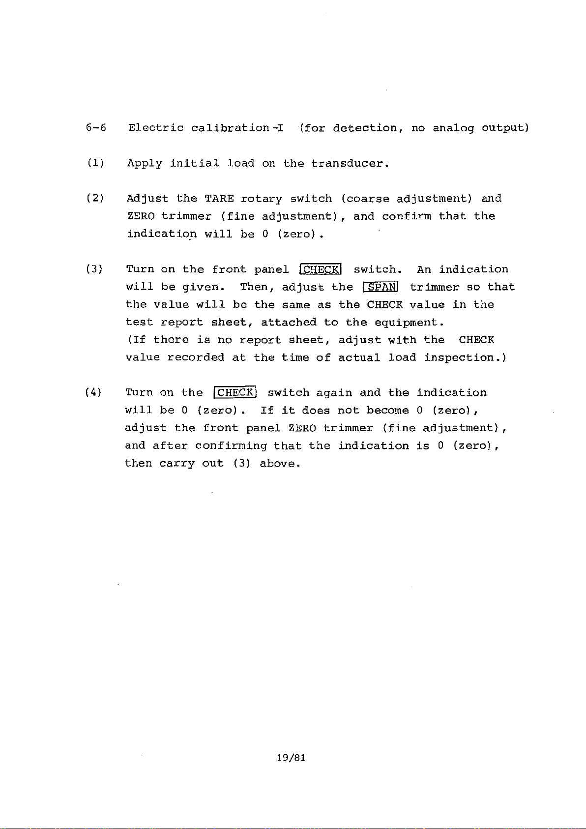
6-6 Electric calibration-1 (for detection, no analog output)
(1) Apply initial load on the transducer.
(2) Adjust the TARE rotary switch (coarse adjustment) and
ZERO trimmer (fine adjustment), and confirm that the
indication will be 0 (zero).
(3) Turn on the front panel
will be given. Then, adjust the 1SPANJ trimmer so that
the value will be the same as the CHECK value in the
test report sheet, attached to the equipment.
(If there is no report sheet, adjust with the CHECK
value recorded at the time of actual load inspection.)
(4) Turn on the
will be 0 (zero). If it does not become 0 (zero),
adjust the front panel ZERO trimmer (fine adjustment),
and after confirming that the indication is 0 (zero),
then carry out (3) above.
CHECK
switch again and the indication
LCHECK1
switch. An indication
19/81
Artisan Technology Group - Quality Instrumentation ... Guaranteed | (888) 88-SOURCE | www.artisantg.com
Page 26
6-7 Electric calibration-II
(for detection, with
analog output)
(1) Apply initial load on the transducer.
(2) With the front panel
0 (zero) indication as well as "C/Z" IJED light.
(If adjustment cannot be made, jointly use the
rotary switch.)
Also, adjust the trimmer No.1 (V-Out) or trimmer No.3
(I-Out), so that voltage output will be 0.000 V or
current output will be 4.00 mA when the indication is
0 (zero).
(3) Turn on the front panel
and analog output will be shown.
In the attached test report sheet, indicated value and
analog value are noted as the check values.
First, adjust the
SPAN
value will be the same.
Then, adjust trimmer No.2 (V-Out) or trimmer No.4
(I-Out) so that the analog value will be the same.
ZERO]
trimmer, adjust to obtain
'TARE'
CHECK
switch. Indication
trimmer so that the indicated
(4) By turning on the ICHECK switch again, the indication
will be 0 (zero). If it does not become 0 (zero),
repeat the above (2) and (3) several times.
20/81
Artisan Technology Group - Quality Instrumentation ... Guaranteed | (888) 88-SOURCE | www.artisantg.com
Page 27

6-8 Registration of each function by set mode
By referring to Section 8. (page 28), register each
function.
Eg.) 1) Setting of decimal point
2) Changeover of the unit
3) Changeover of BCD-OUT true
etc.
ry
6-9 Start-of ,measurement
Turn on the
'Z/S
switch and start the measurement.
As required, set the value of comparative setter.
21/81
Artisan Technology Group - Quality Instrumentation ... Guaranteed | (888) 88-SOURCE | www.artisantg.com
Page 28

§7. FUNCTION IN MEASUREMENT MODE
This function is a function which can be carried out
during normal measurement. Condition at the time of
power supply to this equipment is in this mode.
7-1 Zero set function (Digital tare cancel, hereinafter
abbreviated as Z/S)
A function to make the indication 0 (zero) regardless
of the analog output.
It can be used for tare cancel and the like.
At the time of Z/S function OFF, it will beYY
(Indication data) = (BCD output: Total load) =
(BCD output: Net load) = (a)
But with the Z/S function ON, it will be
(Indication data) = (BCD output: Netload)
Z/S cancel data is the total load data
function is turned ON.
Also, by turning ON the Z/S function, it will be
possible to use AUTO ZERO function and ZERO TRACKING
function.
(1) Z/S ON
By turning ON the front panel Z/S switch, red LED in
the Z/S switch will be lighted, and the total load
value at such time will be memorized and the indication
will be 0 (zero).
Thereafter, the indication will be made according to
formula (b).
(Total—MIT- Z
(hATAgt,
(b)
when the Z/S
22/81
Artisan Technology Group - Quality Instrumentation ... Guaranteed | (888) 88-SOURCE | www.artisantg.com
Page 29
(2) Z/S OFF
By repeating the same operation as above (1), red LED
in the Z/S switch will be put out and the total load
value at such time will be indicated.
Thereafter, the indication will be made according to
formula (a). (However, this function is effective
only when the LED in the A/Z OFF switch is lighted.)
7-2 AUTO ZERO, AUTO ZERO OFF Function
(hereinafter, AUTO ZERO will be abbreviated as A/Z)
As in Z/S function, this function indicates 0 (zero)
regardless of the analog output.
While the Z/S function is a function to determine the
basis of indication (indication 0), A/Z function is
a function for easy understanding of the changed
amount of the data, which will give optional value a
0 (zero), and can indicate 0 repeatedly.
In case of A/Z function OFF, indication will be made
according to the formula (a) or (b) shown in Z/S
function.
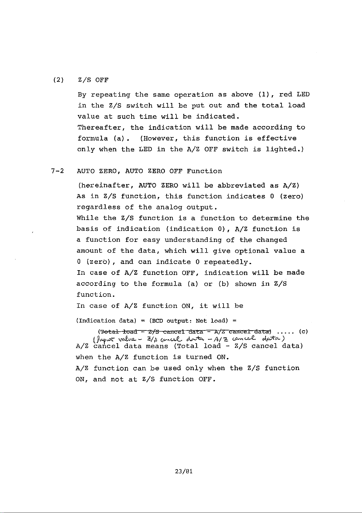
In case of A/Z function ON, it will be
(Indication data) = (BCD output: Net load) =
a a celdata) (c)
— cpb,cia,.. — Ar t CA,K tga— c.tcoreA. )
A/Z cancel data means (Total load - Z/S cancel data)
when the A/Z function is turned ON.
A/Z function can be used only when the Z/S function
ON, and not at Z/S function OFF.
23/81
Artisan Technology Group - Quality Instrumentation ... Guaranteed | (888) 88-SOURCE | www.artisantg.com
Page 30
(1) A/Z ON
By turning ON the front panel A/Z switch, red colored
LED in the A/Z OFF switch will be put out.
(Total load - Z/S cancel data) at such time will be
memorized and the indication will be 0 (zero).
Hereafter, indication will be made according to formula
(c).
Also, it is possible to turn ON the A/Z function
repeatedly without turning OFF the A/Z function. With
A/Z function ON, Z/S function will be locked and Z/S
function OFF will not be accepted.
(2) A/Z OFF
By turning ON the front panel A/Z OFF switch, red
colored LED in the A/Z OFF switch will be lighted,
and thereafter indicate according to formula (b).
Also, with A/Z function OFF, locked condition of Z/S
function will be released and Z/S function OFF will be
possible.
24/81
Artisan Technology Group - Quality Instrumentation ... Guaranteed | (888) 88-SOURCE | www.artisantg.com
Page 31
7-3 Comparative setting function (comparator)
This is a function which will turn ON the rear contact
at above or below the setting value against the indica-
tion.
There are two setting points, HIGH and LOW, and each
can be set at high or low limits. Also, it will output
signals to show that, by setting, it is within the
range of two (2) settings. (OK)
(1) Setting of comparative value
Set the setting values of each 2 points at\the front
panel digital switch. The set values include the sign,
so if rear contact ON is desired at indicated value "+",
set the sign at "+", and if rear contact ON is desired
at indicated value "-", then 6.et the sign at "-".
(2) Setting of comparative conditions
When in standard specification or in back-up data clear,
both HIGH and LOW points will be set at high limits,
and whew-the- indic-ated- -va-lu-e---1-8- above the set value of
9 front panel digital switch, rear contact output will
be ON.
To change the condition, setting contents exchange
function of initial setting will be used.
Also, in case the condition of HIGH is at low limit
and condition of LOW is at high limit, and if setting
value of HIGH a indicated value setting value of
LOW, then contact output of OK will be ON in addition
to contacts of HIGH and LOW. This OK contact can be
controlled by the judgement function of initial setting.
(For the above, refer to initial setting function.)
25/81
Artisan Technology Group - Quality Instrumentation ... Guaranteed | (888) 88-SOURCE | www.artisantg.com
Page 32

(3) Output of comparative results
If the indicated value satisfies the conditions of (2)
against the setting of (1), then contact output will
be ON and front panel LED (color : red) will be ON.
Note : If the indicated value is unsteady in the
vicinity of the set value, contact output will
similary be unsteady.
Eg.1 LOW=high limit setting HIGH high limit setting
indication
HIGH setting value
LOW setting value
a.
HIGH contact
LOW contact oii
OK contact ON
Eg.2
indication
HIGH setting value
LOW setting value
HIGH contact OOFFN
LOW contact OcFF° ON
OK contact ow
ON
OFF
OFF
OFF
LOW=high limit setting HIGH=low limit setting
26/81
Artisan Technology Group - Quality Instrumentation ... Guaranteed | (888) 88-SOURCE | www.artisantg.com
Page 33

7-4 CENTER ZERO function
Turn on the front panel C/Z LED (color: red) when both
the indication is 0 (zero) and the total load value is
less than + 1/2 of 1 digit.
Example 1
Tota l load
Value
+ 1000.0
+ 1000.0
+ 1000.0
+ 1000.0
+ 0.5
+ 0.0
+ 0.0
+ 0.0
+ 0.3
0.3
Z/S cancel Z/S cancel
data data
OFF
+ 1000.0
+ 500.0
— 1000.0
OFF
+ 1000.0
+ 1000.0
OFF
OFF
- 0.3
+ 500.0 + 0 OFF
+ 2000.0 + 0 OFF
— 1000.0 + 0 ON
OFF + 1000.0 OFF
OFF + 0 OFF
OFF + 0 OFF
OFF — 1000.0 OFF
OFF + 0 ON
OFF + 0 ON
OFF + 0 ON
Indcation C/Z
27/81
Artisan Technology Group - Quality Instrumentation ... Guaranteed | (888) 88-SOURCE | www.artisantg.com
Page 34

§8. FUNCTION BY SET MODE (INITIAL SETTING FUNCTION)
This function is for carrying out the various functions
of this equipment and to set required data for such
functions.
Using the attached micro-driver, press the hole located
at front panel SET MODE. Then, SET MODE switch will be
ON, indication will be "P" and will be in SET MODE.
Normal measurement (Measurement Mode) will not be made
while indication is "P". To achieve measurement mode,
turn ON the SET MODE again.
Functions which can be registered by SET MODE are as
follows.
1) ZERO TRACKING
2) Minimum effective digit setting
3) Multiplication
4) Pre-set (weight) cancellation
5) Setting contents exchange
6) Judgment
7) Dummy 0 indication
8) Decimal point indication
9) Sign inversion
10) Sign transfer
11) Unit indication changeover
12) Manual. Z/S function
13) Back-up data clear
Each of the above functions will be registered under
the condition of SET MODE (indication "P").
28/81
Artisan Technology Group - Quality Instrumentation ... Guaranteed | (888) 88-SOURCE | www.artisantg.com
Page 35
8-1 Required switches for SET MODE
During the SET MODE (indication "P" lighted), each
switch on the front panel will have a different meaning
from that in Measurement Mode.
(1) Digital switch (LOW)
Setting function Nos.
(2) Digital switch (HIGH)
Data setting
Set the data per each function set by digital switch(LOW).
(3) Z/Sj switch
Function data register
Contents set by digital switches (HIGH/LOW) will be
registered in internal memory. While this switch is
pressed, indication will show the contents of digital
switch (HIGH). If the switch is released, the
indication will be "P".again.
(4) A/Zj or
Memory dump
Will indicate the data, presently registered within the
function set by digital switch (LOW).
Data will be indicated while the switch is pressed,
and indication will be "P" if switch is released.
(5)
CHECK switch
Self-check
Similar self-check as in initial power feed.
A/Z OFF
switch
29/81
Artisan Technology Group - Quality Instrumentation ... Guaranteed | (888) 88-SOURCE | www.artisantg.com
Page 36

8-2 ZERO TRACKING (Z/T)
While the indication is 0 (zero), it will cancel the
changing indication, due to drift of input data caused
by internal and external reasons.
Z/T will indicate 0 (zero) when the data, with the
exception of 0 (zero), is within a certain width and
time, and the data out of such position will be added
to Z/S cancel value (see 7-1).
Note : This function will be effective by Z/S switch ON
during Measurement Mode, after Set Mode register.
Registration Procedure
(1) Yes or no of Z/T execution will be set at the front
panel, digital switch.
Note 1.
Digital switch LOW
Digital switch HIGH +/-
*1 : For minimum effective digit setting (see 8-3)
*2 : For pre-set (weight) cancellation function (see 8-5)
*3 : For multiplication (see 8-4)
Note 1. : + or - both possible
+/-
Note 1.
0 0
*1
0 x
*2
0 0
0
*3
-- 0: Z/T ineffective
-- 1: Z/T effective
-- 2'b9: Error (E-3)
(Function No.)
(Data)
30/81
Artisan Technology Group - Quality Instrumentation ... Guaranteed | (888) 88-SOURCE | www.artisantg.com
Page 37

(2) Turn ON the WS switch and register the set value at
to internal memory.
(1)
(While the [Z/S1 switch is. ON, value set by digital
switch HIGH will be indicated, and when the switch is
released, "P" will be indicated. "E--3" will be
indicated when there is an error in digital switch
setting. In this case, data set at digital switch
will not be registered. Reconfirm the contents of
the digital switch.)
31/81
Artisan Technology Group - Quality Instrumentation ... Guaranteed | (888) 88-SOURCE | www.artisantg.com
Page 38

(3) Set the data required for Z/T to digital switch
Note 1
Digital switch LOW
Digital switch HIGH + / -
Note 1 : + or - both possible
+/- 0 0 0 0
Note 1
1
0
0
X
0
X (Data)
(Function No.)
'VT
time width setting
— 0 0 sec.
— 1 : 1 sec.
-- 2 : 2.5 sec.
-- 3 : 4 sec.
-- 4 6 sec.
-- 5 : 8 sec.
-- 6%9: Error (E-3)
• Data width to be
zero cancelled
0 0 (Z/T ineffective)
-- 1 1 count or below
r- 2 : 1.5 count or below
— 3 3 count or below
4%9: Error (E-3)
Data
--0
See the following graph for the relation between time width and
data width.
t
Time
t : Time width
d : Data width
32/81
Artisan Technology Group - Quality Instrumentation ... Guaranteed | (888) 88-SOURCE | www.artisantg.com
Page 39

(4) Turn ON the Z/S switch and register the set value at
(3) to internal memory.
(While the Z/S switch is ON, value set by digital
switch HIGH will be indicated, and when the switch is
released, "P" will be indicated. "E-3" will be
indicated when there is an error in digital switch
setting. In this case, data set at digital switch
will not be registered. Reconfirm the contents of
the digital switch.)
33/81
Artisan Technology Group - Quality Instrumentation ... Guaranteed | (888) 88-SOURCE | www.artisantg.com
Page 40

8-3 Minimum effective digit setting function
This function is for setting the minimum digit of
indication, and to determine the increment (indication
change) of such digit.
Also, it is possible to select whether to cut and close
to the right or to leave as 0 (zero), such digits below
the set digit.
(Example)
- Normal increment
- When minimum digit is
0 and increment is 2
10
- When minimum digit is
below to be cut and
increment is 1
} 1992 ± 1994 ÷ 1994 -÷ 1996 1996
101,
.9- 1994 a 1995
1993
199 199 + 200
+1996
a 200
(Note)
This function is effective for BCD output data as
well, but close to the right function will, in BCD
output, become leave as 0 (zero).
-0- 1997
+ 200
34/81
Artisan Technology Group - Quality Instrumentation ... Guaranteed | (888) 88-SOURCE | www.artisantg.com
Page 41

Registration Procedure
(1) Yes or no to execute minimum effective digit setting
will be set.
Note 1
Digital switch LOW I +1-
00 TO 10A (Function No.)
Note 1 *1 *2 *3
'Digital switch HIGH +/- 0 I X iXTh. X (Data)
- 0
- 1
*1 : For pre-set (weight) cancellation function (see 8-5)
*2 : For multiplication (see 8-4)
*3 : For Z/T (see 8-2)
Note 1 : or - both possible.
: minimum effective digit
settingtqffective
: minimum effective digit
setting **effective
: Error (E-3)
(2) Turn ON the Z/S
at (1) to internal memory.
(While the Z/S switch is ON, value set by digital
switch HIGH will be indicated, and when the switch is
released, "P" will be indicated. "E-3" will be
indicated when there is an error in digital switch
setting. In this case, data set at digital switch
will not be registered. Reconfirm the contents of
the digital switch.)
switch and register the set value
35/81
Artisan Technology Group - Quality Instrumentation ... Guaranteed | (888) 88-SOURCE | www.artisantg.com
Page 42

(3) Set the data required for minimum effective digit
setting function.
Note 1
Digital switch LOW
Note 1
Digital switch HIGH
Note 1 : or - both possible
/
(Function No.)
(Data)
• Minimum effective
digit setting
--o : 100
- -1 : 101
- -2 : 102
- : Error (E-3)
'Indication below
minimum digit
—0 : leave zero
- -1 : blank (close to
right)
— 2"9 : Error (E-3)
• Indication increment of
minimum digit
36/81
—0 : 0,1,2,3,4,5,6,7,8,9
—1 : 0,2,4,6,8
—2 : 0,5
- : Error (E-3)
Artisan Technology Group - Quality Instrumentation ... Guaranteed | (888) 88-SOURCE | www.artisantg.com
Page 43
(4) Turn ON thelZ/S switch and register the set value
at (3) to internal memory.
(While the Z/Slswitch is ON, value set by digital
switch HIGH will be indicated, and when the switch is
released, "P" will be indicated. "E-3" will be
indicated when there is an error in digital switch
setting. In this case, data set at digital switch
will not be registered. Reconfirm the contents of
the digital switch.)
37/81
Artisan Technology Group - Quality Instrumentation ... Guaranteed | (888) 88-SOURCE | www.artisantg.com
Page 44

8-4 Multiplication function
This function will indicate the data multiplied by
constant and BCD output.
According to the constant, maximum indication and
maximum setting value of digital switch will change.
Constant Maximum indication (or set value)
X 2
X 1
X .1/2
X 1/5
+/-
+/-
+/-
+/-
19998
9999
4999
1999
In standard specification and after back-up data clear
the constant will be at (X1).
Note : If the
transfer from measurement mode
the constant cannot be changed
Be sure to register under
Z/S, switch is ON just prior to the
to set mode,
in this function.
Z S
switch off
condition.
38/81
Artisan Technology Group - Quality Instrumentation ... Guaranteed | (888) 88-SOURCE | www.artisantg.com
Page 45

Registration Procedure
(1) Set the multiplication constant
Note 1
Digital switch LOW
Digital switch HIGH
▪ /
Note 1 *1 *2
0 0
+/-
0
0
0
*3
X
• Multiplication
constant
(Function No.)
(Data)
0 : x 1
1 x 1/2
"-2 : X 1/5
3 : X 2
4.1,9 : Error (.E-3)
*1 : For minimum effective digit setting function (see 8-3)
*2 : For pre-set (weight) cancellation function (see 8-5)
*3 : For Z/T (see 8-2)
Note 1 : or - both possible
(2) Turn ON the
at (1) to internal memory.
(While the Z/5) switch is ON, value set by digital
switch HIGH will be indicated, and when the switch is
released, "P" will be indicated. "E-3" will be
indicated when there is an error in digital switch
setting. In this case, data set at digital switch
will not be registered. Reconfirm the contents of
the digital switch.)
Z/S' switch and register the set value
39/81
Artisan Technology Group - Quality Instrumentation ... Guaranteed | (888) 88-SOURCE | www.artisantg.com
Page 46

8-5 Pre-set (weight) cancellation function
This function is for comparative setting, with a
method where a reference point (quantitative point)
is established on digital switch HIGH and to set the
excess and deficiency data (cancel portion) against
such point on digital switch LOW.
Eg.) When HIGH contact ON at quantitative 1000 kg,
and LOW contact ON at pre-quantitative 200 kg
(indication 800 kg), then,
• Method to date :
Digital switch HIGH setting
+01000
Digital switch LOW setting
+00800
• By using pre-set (weight) cancellation function:
Digital switch HIGH setting 4- +01000
Digital switch LOW setting -00200
Note 1) Consider polarity when setting digital switch
LOW.
If set as +00200, contact on LOW side will be
ON at indication +01200.
40/81
Artisan Technology Group - Quality Instrumentation ... Guaranteed | (888) 88-SOURCE | www.artisantg.com
Page 47

1Registration Procedure
(1) Set yes or no to execute pre-set (weight) cancellation
function
Digital switch LOW
*1 : For minimum effective digit setting function (see 8-3)
*2 : For multiplication function (see 8-4)
*3 : For Z/T (see 8-2)
Note 2 : + or - both possible
0 0 0 0 0
: Pre-set (weight)
1 : Pre-set (weight)
2'%,9 : Error (E-3)
(Function No.)
(Data)
cancellation function
ineffective
cancellation function
effective
41/81
Artisan Technology Group - Quality Instrumentation ... Guaranteed | (888) 88-SOURCE | www.artisantg.com
Page 48
(2) Turn ON the
Z/s switch and register the set value
at (1) to internal memory.
(While the 'Z/S switch is ON, value set by digital
switch HIGH will be indicated, and when the switch
is released, "P" will be indicated. When there is an
error in digital switch setting, data set at digital
switch will not be registered. Reconfirm the contents
of digital switch.)
(3) When registration is finished and measurement mode
is carried out, LED for contact monitor on th front
surface will be green.
(4) Refer to preceeding example and select the set value.
42/81
Artisan Technology Group - Quality Instrumentation ... Guaranteed | (888) 88-SOURCE | www.artisantg.com
Page 49

8-6 Comparative setting condition changeover function
Can select comparative condition of setting points
for HIGH and LOW each.
Comparative condition is a condition to turn ON the
relay contact, according to the size relation of
setting value and indication value, and will be as
the following figure.
\\\\
\ Contact ON
f. 1
Setting point
High Limit Setting
+F.S.-
Setting point
Low Limit Setting
43/81
Artisan Technology Group - Quality Instrumentation ... Guaranteed | (888) 88-SOURCE | www.artisantg.com
Page 50

Therefore, as this equipment is incorporated with
2 points of setting points, 4 points of setting methods
are possible as shown below. Furthermore, with the
setting method (3), output of OK contact can be obtained
in addition to 2 points of contacts HIGH and LOW.
IGH
Low contact ON field
\-\\\.\
High contact ON field
(1) High high limit setting
(2) Low low limit setting
.s.
(3) High low limit setting
HIGH
LOW
(4) Low high limit setting
IGH
F.S.
44/81
Artisan Technology Group - Quality Instrumentation ... Guaranteed | (888) 88-SOURCE | www.artisantg.com
Page 51

Registration Procedure'
(1) Set HIGH and LOW each of comparative setting conditions.
Note 1
Digital switch LOW
Digital switch HIGH
*1 : For judgment function (see 8-7)
Note 1 : + or - both possible
+1 -
Note 1 *1
0
+/-
0 I 0
2
0
•Comparative condition
—0 : High limit setting
—1 : Low limit setting
- : Error (E-3)
•Comparative condition for
digital switch HIGH
—0 : High limit setting
—1 : Low limit setting
: Error (E-3)
(Function No.)
(Data)
for digital switch LOW
(2) Turn ON the Z /S
(1) to internal memory.
(While the 1Z/S1 switch is ON, value set by digital
switch HIGH will be indicated, and when the switch
is released, "P" will be indicated. "E-3" will be
indicated when there is an error in digital switch
setting. In this case, data set at digital switch
will not be registered. Reconfirm the contents of
the digital switch.)
switch and register the set value at
45/81
Artisan Technology Group - Quality Instrumentation ... Guaranteed | (888) 88-SOURCE | www.artisantg.com
Page 52

8-7 Judgment function
As described in 8-6, if the comparative conditions of
comparative setting function are set as
I) HIGH
2) LOW
low limit setting
high limit setting
and the indication value satisfies the condition of
setting value of LOW Indication value g setting value of HIGH ... (1)
then it is possible to output OK contact in addition
to 2 contacts of HIGH and LOW.
This function is to further control such OK contact
output by external signal, with
CHECK switch used
for the external signal.
Operationally, normally there will be no OK contact
output when the indication value is satisfying the
condition of formula (1), but will output by turning
CHECK'ON the (CHECK( switch. By putting the switch
ON again, output will be OFF. Once the OK contact is
ON, the condition will be maintained unless input of
switch is made again, so even if the conditionCHECK
of the indication value no longer satisfies the
conditions of formula (1), OK contact output will
continue to be in output.
Relationship between data fluctuation and input/output
signal will be as follows.
46/81
Artisan Technology Group - Quality Instrumentation ... Guaranteed | (888) 88-SOURCE | www.artisantg.com
Page 53

HIGH
setting value
LOW
sett3_ng valu
Data fluctuation by time
HIGH
contact
contact
CHECK
input
Ott
OFF
Olt
OFF
Oil
OFF -
OH
OK
contact OFF
Remarks : 1 -' judgement ON
2 - judgement OFF
Note : By executing this function, conventional CAL
function by !CHECK' switch cannot be carried out.
47/81
Artisan Technology Group - Quality Instrumentation ... Guaranteed | (888) 88-SOURCE | www.artisantg.com
Page 54

Registration Procedure'
(1) Set yes or no of judgment function execution
Note 1
Digital switch LOW
Digital switch HIGH
*1 : For comparative setting condition changeover function
(see 8-6)
Note 1 : + or - both possible
+ / -
Note 1
+/- 0
0
0
0
*1 *1
0
X X X
0 : Judgment function
1 : Judgment function
- 2,k,9 : Error (E-3)
2
0
ineffective
effective
(Function No.)
(Data)
(2) Turn ON the 1Z/S1 switch and register the set value at
(1) to internal memory.
(While the Z/S switch is ON, value set by digital
switch HIGH will be indicated, and when the switch is
released, "P" will be indicated. "E-3" will be
indicated when there is an error in digital switch
setting. In this case, data set at digital switch
will not be registered. Reconfirm the contents of
the digital switch.)
48/81
Artisan Technology Group - Quality Instrumentation ... Guaranteed | (888) 88-SOURCE | www.artisantg.com
Page 55

8-8 Dummy 0 indication
Normally, dummy 0 (leave 0) will be lighted at the
right end of 4 digits indication.
Registration Procedure
(1)
Note : This function cannot be registered if
switch is ON in the measurement mode, just prior
to set mode ON ("P" indication). ("E-3" will be
indicated at the time of registration in set
mode.)
Be sure to enter set mode after Z/S switch OFF.
Set yes or no of dummy
Note
Digital switch LOW
Digital switch HIGH
+/-
Note 1 *1
+ / -
0 indication
1
of
0
0
x x
0
*2 *3
4
0
x x
o : dummy 0
-- 1 : dummy 0
2q,9 : Error (E-3)
z/s1
(Function No.)
(Data)
ineffective
effective
*1 : For sign transfer indication function (see 8-11)
*2 : For sign inversion function (see 8-10)
*3 : For decimal point indication (see 8-9)
Note 1 : + or - both possible
49/81
Artisan Technology Group - Quality Instrumentation ... Guaranteed | (888) 88-SOURCE | www.artisantg.com
Page 56

(2) Turn ON the
at (1) to internal memory.
(While the Z/S switch is ON, value set by digital
switch HIGH will be indicated, and when the switch is
released, "P" will be indicated. "E-3" will be
indicated when there is an error in digital switch
setting. In this case, data set at digital switch
will not be registered. Reconfirm the contents of
the digital switch.)
ZIS
switch and register the set value
50/81
Artisan Technology Group - Quality Instrumentation ... Guaranteed | (888) 88-SOURCE | www.artisantg.com
Page 57

8-9 Decimal point indication
Add decimal point to indication data
Registration procedure
Note : This function cannot be registered if
switch is ON in the measurement mode, just prior
to set mode ON ("P" indication). ("E-3" will be
indicated at the time of registration in set mode)
Be sure to enter set mode after jZ/SI switch OFF.
(1) Set necessary digits of decimal point
Note 1
Digital switch LOW
Digital switch HIGH
/ -
Note 1 *1 *2
/ -
0 0 0 0
0
1 . g . . 9 - £3
104 103 102 10'
— 1 : 101
— 2 : 102
— 3 : 103
- - 4 : 104
5'1,9 : Error (E-3)
lz/s1
4
*3
• Decimal point
indication digit
0 : OFF (No decimal
(Function No.)
(Data)
point)
*1 : For sign transfer indication (see 8-11)
*2 : For sign inversion function (see 8-10)
*3 : For dummy 0 indication (see 8-8)
Note 1 : +1- both possible
51/81
Artisan Technology Group - Quality Instrumentation ... Guaranteed | (888) 88-SOURCE | www.artisantg.com
Page 58
(2) Turn ON the Z/S switch and register the set value
at (1) to internal memory..
(While the Z/S switch is ON, value set by digital
switch HIGH will be indicated, and when the switch is
released, "P" will be indicated. "E-3" will be
indicated when there is an error in digital switch
setting. In this case, data set at digital switch
will not be registered. Reconfirm the contents of
the digital switch.)
52/81
Artisan Technology Group - Quality Instrumentation ... Guaranteed | (888) 88-SOURCE | www.artisantg.com
Page 59

8-10 Sign inversion function
Will invert the sign of indication and BCD output.
Therefore, it will be (-) indication at (+) data and
(+) indication at (-) data.
Registration Procedure
Note : This function cannot be registered if IZ/S[switch
is ON in the measurement mode, just prior to
set mode ON ("P" indication). ("E-3" will be
indicated at the time of registration in set mode)
Be sure to enter set mode after [Z/S switch OFF.
(1) Register yes or no of sign inversion function execution.
Note 1
Digital switch LOW
Digital switch HIGH
*1 : For sign transfer indication (see 8-11)
*2 : For decimal point indication (see 8-9)
*3 : For dummy 0 indication (see 8-8)
Note 1 : +/- both possible
/ -
Note 1 *1 *2 *3
/ -
0 0
-.a
0 X
0 0
4
0 : Sign inversion function
ineffective
1 : Sign inversion function
effective
2q,9 : Error (5-3)
(Function No.)
(Data)
53/81
Artisan Technology Group - Quality Instrumentation ... Guaranteed | (888) 88-SOURCE | www.artisantg.com
Page 60

(2) Turn ON the Z/S switch and register the set value
at (1) to internal memory.
(While the Z/S switch is ON, value set by digital
switch HIGH will be indicated, and when the switch is
released, "P" will be indicated. "E-3" will be
indicated when there is an error in digital switch
setting. In this case, data set at digital switch
will not be registered. Reconfirm the contents of the
digital switch.)
54/81
Artisan Technology Group - Quality Instrumentation ... Guaranteed | (888) 88-SOURCE | www.artisantg.com
Page 61

8-11 Sign transfer function
Normally, ( ) sign is fixed at the left end of the
front panel indicator, but with this function, (-)
sign will transfer to left/right according to the
digit of indication.
Registration Procedure
Note : This function cannot be registered if LZ/SI switch
is ON in the measurement mode, just prior to set
mode ON ("P" indication). ("E-3" will be
indicated at the time of registration in set mode)
Be sure to enter set mode after WS' switch OFF.
(1) Register yes or no of sign transfer function execution.
Note 1
Digital switch LOW
Digital switch HIGH
*1 : For indication of sign inversion (see 8-10)
*2 : For decimal point indication (see 8-9)
*3 : For dummy 0 indication (see 8-8)
Note 1 : +/- both possible
+ / -
Note 1
+ / -
0 0 0
*1 *2
0
x
0 : Sign transfer function
1 : Sign transfer function
2q9 : Error (E-3)
4
0
*3
ineffective
effective
(Function No.)
(Data)
55/81
Artisan Technology Group - Quality Instrumentation ... Guaranteed | (888) 88-SOURCE | www.artisantg.com
Page 62
(2) Turn ON the 1 Z/S1 switch and register the set value
at (1) to internal memory.
(While the
Z/S switch is ON, value set by digital
switch HIGH will be indicated, and when the switch is
released, "P" will be indicated. "E-3" will be
indicated when there is an error in digital switch
setting. Inthis case, data set at digital switch will
not be registered. Reconfirm the contents of the
digital switch.)
56/81
Artisan Technology Group - Quality Instrumentation ... Guaranteed | (888) 88-SOURCE | www.artisantg.com
Page 63
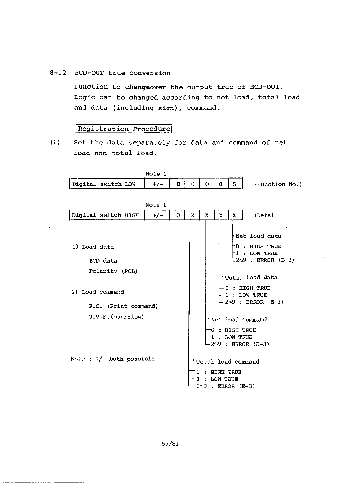
8-12 BCD-OUT true conversion
Function to chengeover the output true of BCD-OUT.
Logic can be changed according to net load, total load
and data (including sign), command.
Registration Procedure
(1) Set the data separately for data and command of net
load and total load.
Note 1
Digital switch LOW + / -
Note 1
Digital switch HIGH + / -
1) Load data
BCD data
Polarity (POL)
2) Load command
P. C . (Print command)
0.V.F.(overflow)
0 0
0 0
'Net load command
—0 : HIGH TRUE
--1 : LOW TRUE
—2'1)9 : ERROR (E-3)
5
•Net load data
-0 : HIGH TRUE
-1 : LOW TRUE
_2ru9 : ERROR (E-3)
'Total load data
--0 : HIGH TRUE
--1 : LOW TRUE
(Function No.)
(Data)
: ERROR (E-3)
Note : +/- both possible
57/81
Artisan Technology Group - Quality Instrumentation ... Guaranteed | (888) 88-SOURCE | www.artisantg.com
'Total load command
--O : HIGH TRUE
--1 : LOW TRUE
: ERROR (E -3)
Page 64
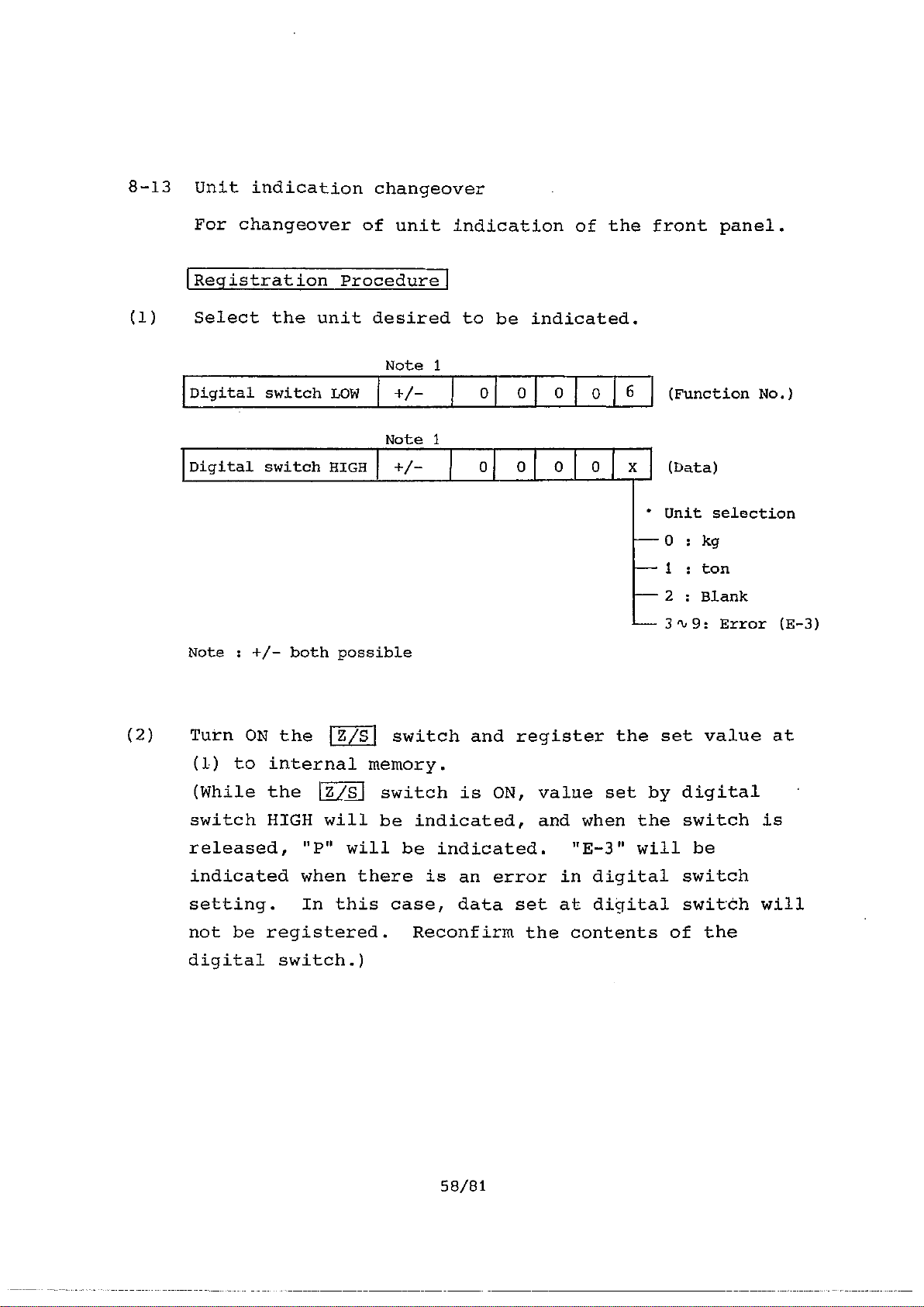
8-13 Unit indication changeover
For changeover of unit indication of the front panel.
Registration Procedure
(1) Select the unit desired to be indicated.
Note 1
Digital switch LOW
Digital switch HIGH I +/-
Note : +/- both possible
(2) Turn ON the
(1) to internal memory.
(While the Z/S switch is ON, value set by digital
switch HIGH will be indicated, and when the switch is
Z/S
6
+/-
Note 1
0
0 0
0
0 0 0 0 x
(Function No.)
(Data)
• Unit selection
- -- 0 : kg
--- 1 : ton
- -- 2 : Blank
3 '1,9: Error (E-3)
switch and register the set value at
released, "P" will be indicated. "E-3" will be
indicated when there is an error in digital switch
setting. In this case, data set at digital switch will
not be registered. Reconfirm the contents of the
digital switch.)
58/81
Artisan Technology Group - Quality Instrumentation ... Guaranteed | (888) 88-SOURCE | www.artisantg.com
Page 65

8-14 Manual Z/S function
This is a function to confirm the Z/S cancellation
value in Z/S function (7-1).
Registration Procedure
(1) Set the function No.
Note 1
Digital switch LOW +/- 0
Note : + or - both possible
0 0
0
(Function No.)
8
(2) By turning ON IA/Z switch or IA/Z OFF switch, Z/S
cancellation value will be indicated while it is ON.
Use for confirmation of Z/S cancellation value.
59/81
Artisan Technology Group - Quality Instrumentation ... Guaranteed | (888) 88-SOURCE | www.artisantg.com
Page 66
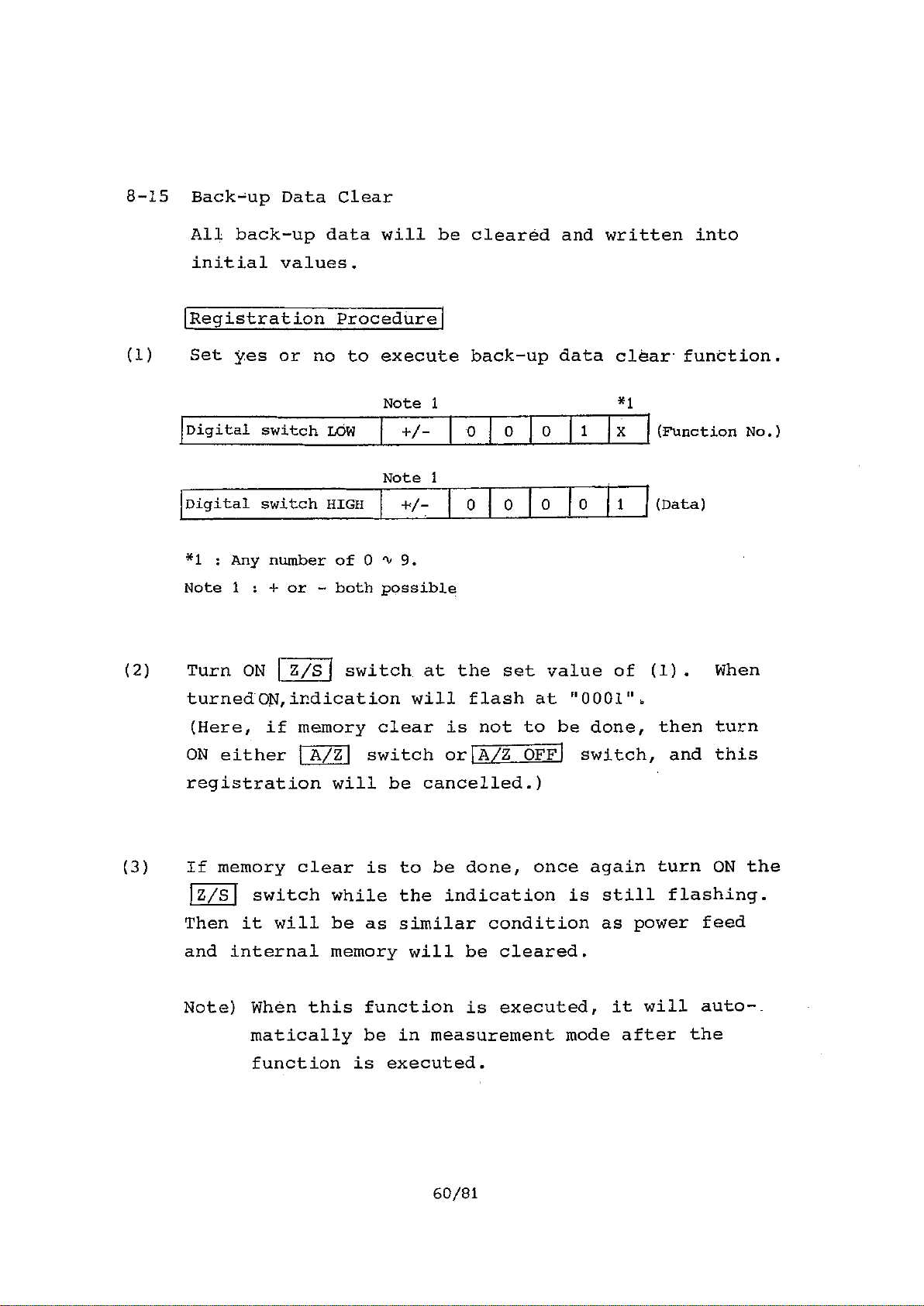
8-15 Back-up Data Clear
All back-up data will be cleared and written into
initial values.
Registration Procedure
(1) Set yes or no to execute back-up data clear function.
Note 1
Digital switch LOW
Digital switch HIGH
*1 : Any number of 0 9.
Note 1 : + or - both possible
+ / -
Note 1
+/:
0
0 0
0 0
*1
1
(Function No.)
(Data)
1
(2) Turn ON Z/S switch at the set value of (1). When
turnedON,indication will flash at "0001".
(Here, if memory clear is not to be done, then turn
ON either A/Z switch or
IA/Z OFF
switch, and this
registration will be cancelled.)
(3) If memory clear is to be done, once again turn ON the
Z/S
switch while the indication is still flashing.
Then it will be as similar condition as power feed
and internal memory will be cleared.
Note) When this function is executed, it will auto-
matically be in measurement mode after the
function is executed.
60/81
Artisan Technology Group - Quality Instrumentation ... Guaranteed | (888) 88-SOURCE | www.artisantg.com
Page 67

§9.
SELF-CHECK FUNCTION
At the time of power feed or by front panel
switch ON during set mode ("P" indication), self-check
can be made.
As the contents of self-check, followings will be done.
1) ROM check
2) RAM check
3) Back-up check
4) A/D check
5) Indication check
§10. ERROR INDICATION
When the following various errors should occur, each
[CHECK]
Program check
Memory check
Back-up check
Operation check of internal
A/D converter
Check abnormal indication
( 1 )
will be indicated and rear panel ERROR contact will
be ON. Also, the bit of BCD-OUT connector No.25 pin
(ERROR) will be ON.
Data over
Will be indicated when input data exceeds indication
maximum value. Normally, indication maximum value is
9999, but when multiplication function (see 8-4) is
used, it will be 4999 at x 1/2, 1999 at x 1/4 and
19998 at x 2.
61/81
Artisan Technology Group - Quality Instrumentation ... Guaranteed | (888) 88-SOURCE | www.artisantg.com
Page 68

(2)
E - 0
ROM error
Will be indicated when error is discovered during self-
check per Section 9. When this error is indicated, the
program will stop. Cut off the power then refeed.
If "E-0" is still indicated, please contact our sales
representative.
(3)
(4)
E - 1
RAM error
Will be indicated when error is discovered during self-
check per Section 9. When this error is indicated, the
program will stop. Cut off the power then refeed.
If "E-1" is still indicated, please contact our sales
representative.
E - 2
Back-up data error
Will be indicated when error is discovered during self-
check per Section 9. It will light and indicate for
about 1 second and then proceed to next operation.
When this indication is given, it will be judged that
there is abnormality in the back-up data, and all data
registered per Sections 7 and 8 will be cancelled, and
will be in standard specification condition. Therefore,
all digital functions should be registered again.
Normally, back-up data will remain memorized for about
1 month, even when the power is cut off.
If "E-2" indication is repeated many times, please
contact our sales representative.
62/81
Artisan Technology Group - Quality Instrumentation ... Guaranteed | (888) 88-SOURCE | www.artisantg.com
Page 69

(5)
E - 3
Key operation error
Will be indicated when a wrong digital switch is set,
(6)
(7)
while
Also,
mode, it could be indicated if
prior to turning the
mode).
Digital switch setting value error
Will be indicated when the setting value of digital
switch during measurement mode should exceed the
indication maximum value.
Reconfirm the setting value.
X XX X X
A/D error
Will be indicated if abnormality in internal A/D
registering the data in set mode of Section 8.
depending on the registration function during set
switch is ON just
E - 4
1SET MODE
Z/S1
switch ON (measurement
converter is discovered when self-check in set mode
is made.
Method of checking A/D converter is, first, input REF.
voltage of 1V to A/D and confirm if digital output is
within 10000 ± 10 count. In all, digital output
should be confirmed 10 times.
If more than ± 10 count is detected, its value and
number of confirmation order
Eg.) If the 5th confirmation
Indication will be
63/81
will be indicated.
is 9876,
98765
Artisan Technology Group - Quality Instrumentation ... Guaranteed | (888) 88-SOURCE | www.artisantg.com
Page 70

This indication will be released by
!CHECK
switch ON.
If there is no error thereafter, it will move to
indication check.
If error indication is repeated several times,
please contact our sales representative.
Artisan Technology Group - Quality Instrumentation ... Guaranteed | (888) 88-SOURCE | www.artisantg.com
Page 71

§11, SET MODE SETTING VALUE TABLE
Switch (HIGH) for setting the contents are expressed
as follows.
4/- 00000
10°
101
102
103
104
+/-
Data (HIGH)
Function Na (LOW)
+1- 00000
digit
10"
value Setting contents
0
1
ZIT OFF
ON
+1- 00001
+/- 00002
101
102
103
10" 0
lot
1O
101
102
0
Multiplication constant X 1/2
2
3
0
Preset (weight) cancellation OFF
1
0
Minimum effective digit setting OFF
1
X ..1
X 1/5
X 2
ON
ON
Z/T OFF Approx. 1 sec.
I
2
3
4
5
0
1
2
3
0
1
0
1
0
1
Z/Talme width Approx. 2.5 sec.
Approx. 4 sec.
Approx. 6 sec.
Approx. 8 sec.
Z/T OFF Less than 1
Z/T Data width
Less than 1.5
Less than 3
Comparative setting condition High limit
(LW) Inv/ limit
Comparative setting condition High limit
Low limit
Judgement fucntion OFF
ON
65/81
Artisan Technology Group - Quality Instrumentation ... Guaranteed | (888) 88-SOURCE | www.artisantg.com
Page 72

+/-
00003
10"
0
Minimum effective digit
1
2
10"
10'
102
00004
+/-
+/- 00005
10' 0
102
10"
10'
102
I0'
10" 0
101
102
0
0
0
2
0
1
0
1
2
:3
4
0
1
0
1
1
1
1
Below minimum effective 0 display
1
digit indication
Minimum 0,1,2,3,4,5,0,7,8,9
1
effective digit 0,2,4,6,8
indication 0,5
Dummy 0 ON
Decimal point 10-1
Sign inversion ON
Sign trnasfer OFF
BCD output logic,Net load data
BCD output logic,Total load dataHigh true
BCD output logic, Net load CaatriandHigh true
OFF
10-2
10-3
10-a
OFF
ON
High true
Irm true
I. true
Ta w true
+/-
+/-
00000
00007
103
10"
10'
°
1 command Lcw true
0
1
2
0
BCD output logic, To load High true
Unit TON
blank
Unused
1
2
9
+/-
00008
10" --
0 --
Z/S camel data
104
+I- .
+/-
0001X
10'
0
1
Ineffective
Back-up data clear _
Note 1 : Cannot register if IZ/SI switch is ON just prior to
turning on the set mode switch.
1
66/81
Artisan Technology Group - Quality Instrumentation ... Guaranteed | (888) 88-SOURCE | www.artisantg.com
Page 73

§12. ANALOG ADJUSTMENT
Although standard internal adjustments have been made
at the time of shipment from the factory, changes can
be made by the following procedure, if various changes
are required.
12-1 Standard parts adjustment
(1)
(2)
(3)
(4)
(5)
(6)
(7)
(8)
(9)
Bridge voltage
GAIN
Sensitivity
TARE cancel
CHECK value
Indication
Unit
Power voltage
BCD-OUT
(10) ZERO TRACKING
(11) Multiplication
(12) Comparative setting
DC5V
X2000 times
10V output at 1 mV/V input
0 mV/V
approx. 8V
10000 indication at 10V output
(in conversion)*
Select kg *
AC 100V ± 10% 50/60 Hz
Open collector
True
Total load data/command ... High true
Net load data/command ... High true *
Time width 0, data width 0
(no execution)
Constant 1
HIGH/LOW high limit setting *
Pre-set (weight) cancellation,
judgment function (no execution)*
(13) Minimum effective
digit setting
loe digit *
0,1,2,3,4,5,6,7,8,9
indication *
*: Can be changed by initial setting function
67/81
Artisan Technology Group - Quality Instrumentation ... Guaranteed | (888) 88-SOURCE | www.artisantg.com
Page 74
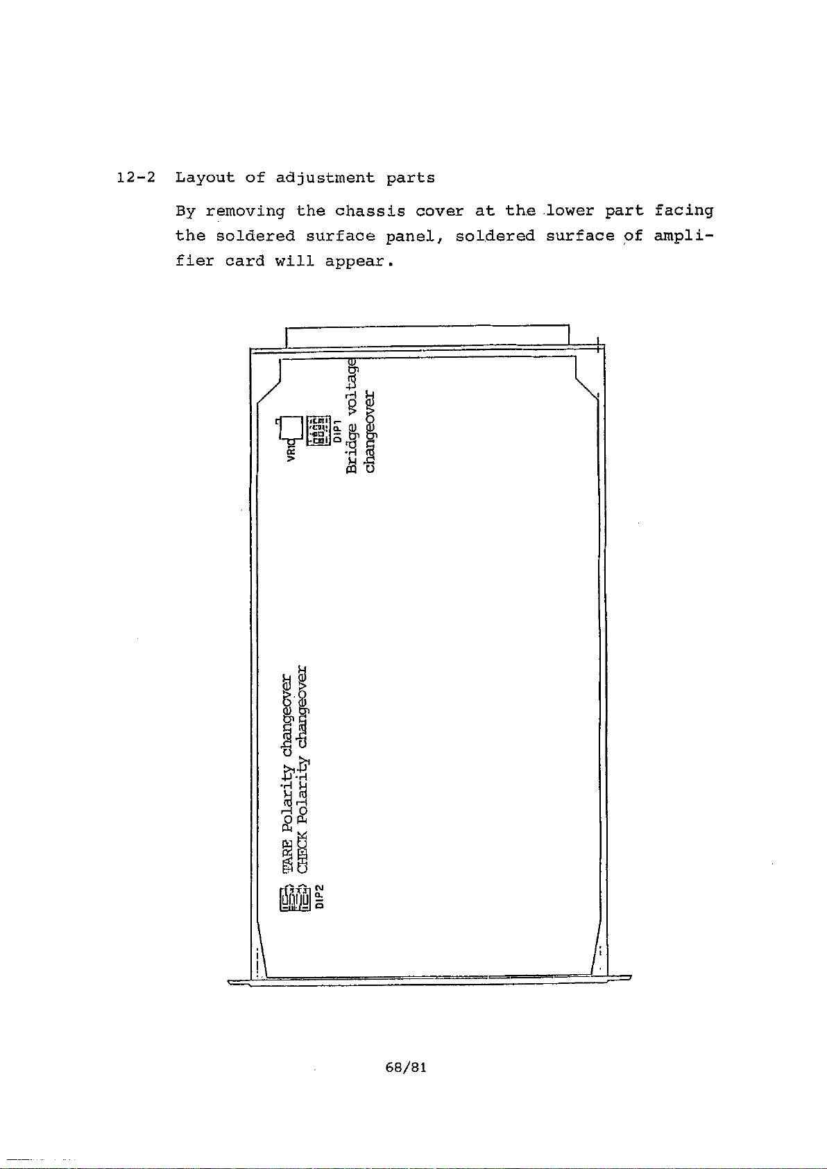
12-2 Layout of adjustment parts
By removing the chassis cover at the lower part facing
the soldered surface panel, soldered surface of ampli-
fier card will appear.
68/81
Artisan Technology Group - Quality Instrumentation ... Guaranteed | (888) 88-SOURCE | www.artisantg.com
Page 75
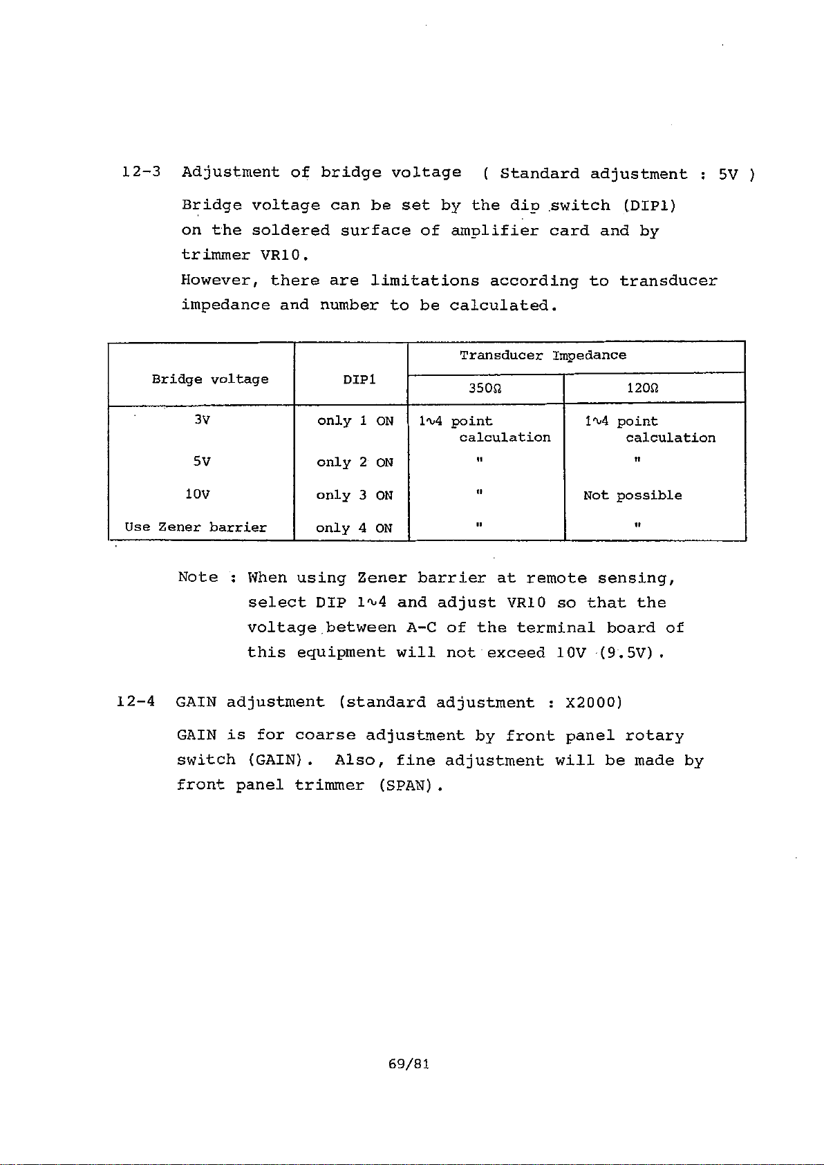
12-3 Adjustment of bridge voltage ( Standard adjustment : 5V )
Bridge voltage can be set by the dip switch (DIP1)
on the soldered surface of amplifier card and by
trimmer VR10.
However, there are limitations according to transducer
impedance and number to be calculated.
Transducer Impedance
Bridge voltage
DIP1
35012
120g
3V
5V
10V
Use Zener barrier
only 1 ON
only 2 ON
only 3 ON
only 4 ON
1'4 point
calculation
il
it
II
1"4 point
Not possible
Note : When using Zener barrier at remote sensing,
select DIP 1'4 and adjust VRIO so that the
voltage between A-C of the terminal board of
this equipment will not exceed 10V (9.5V).
12-4 GAIN adjustment (standard adjustment : X2000)
GAIN is for coarse adjustment by front panel rotary
switch (GAIN). Also, fine adjustment will be made by
front panel trimmer (SPAN).
calculation
ti
11
69/81
Artisan Technology Group - Quality Instrumentation ... Guaranteed | (888) 88-SOURCE | www.artisantg.com
Page 76

Required GAIN (G) can be obtained by the following
formula.
VA
G
Where,
Bridge voltage : Vb [V]
Output of used transducer (actual output) : E [mV/V]
Required output voltage Ve [mV]
Required GAIN : G [times]
Related formula of GAIN rotary switch setting and GAIN
are as the following table.
Vb X E
Setting
GAIN.
5
0
1
2
3 1275
4
5 765
6 510
7
8
9
For SPAN adjustment, adjust 1/1,‘,3/4 against each of
the above GAIN value.
2040
1785
1530
1020
255
2040
1785
0
GAIN setting switch
Note : GAIN values in this section are based on analog
output (V-Out).
Indicated data will be 1/10 values.
70/81
Artisan Technology Group - Quality Instrumentation ... Guaranteed | (888) 88-SOURCE | www.artisantg.com
Page 77
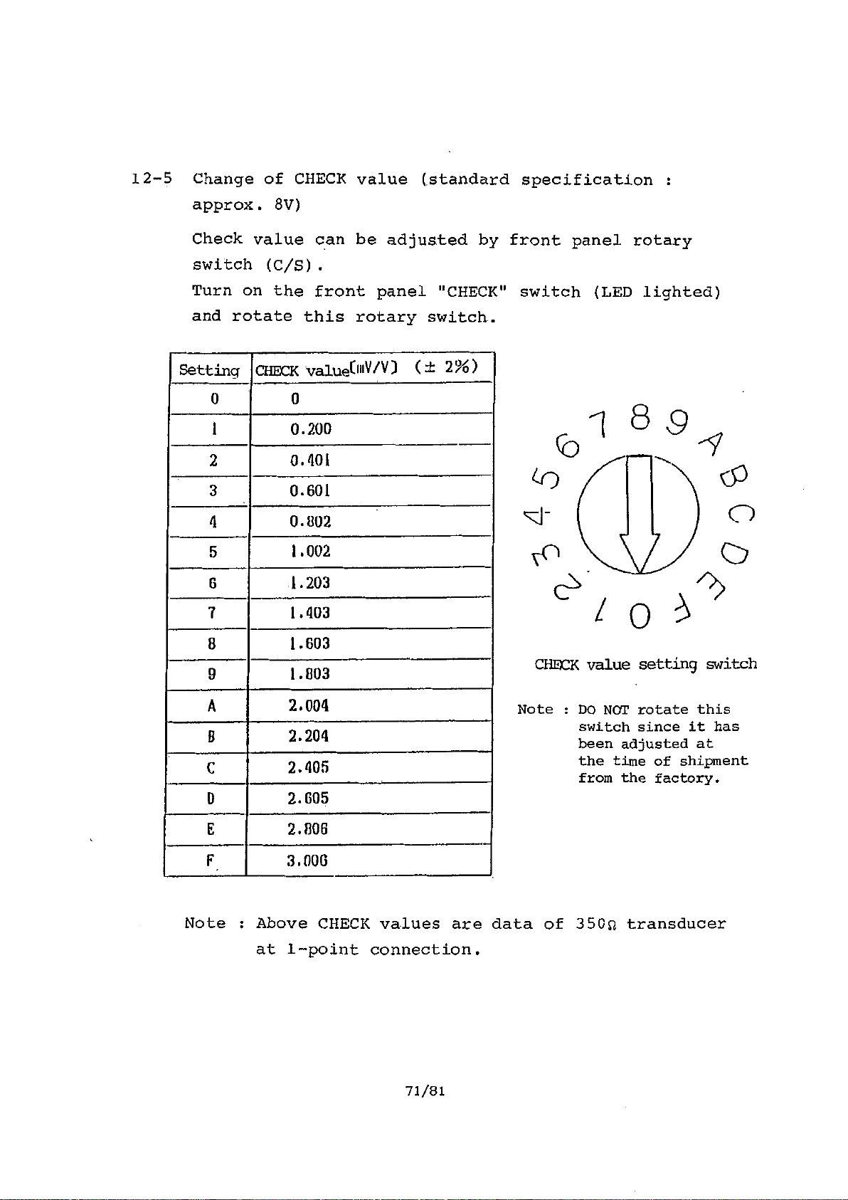
12-5 Change of CHECK value (standard specification :
approx. 8V)
Check value can be adjusted by front panel rotary
switch (C/S).
Turn on the front panel "CHECK" switch (LED lighted)
and rotate this rotary switch.
Setting
0 0
1
2 0.401
3
4
5
6
7
8
9
A
8
C
0
CHECK value(mV/V) (-± 2%)
0.200
0.601
0.1302
1.002
1.203
1.403
1.603
1.803
2.004
2.204
2.405
2.605
1 8 9 -1
cP
Z
CHECK value setting switch
Note : DO NOT rotate this
switch since it has
been adjusted at
the time of shipment
from the factory.
E
F 3.000
Note : Above CHECK values are data of 350Q transducer
Artisan Technology Group - Quality Instrumentation ... Guaranteed | (888) 88-SOURCE | www.artisantg.com
2.806
at 1-point connection.
71/81
Page 78
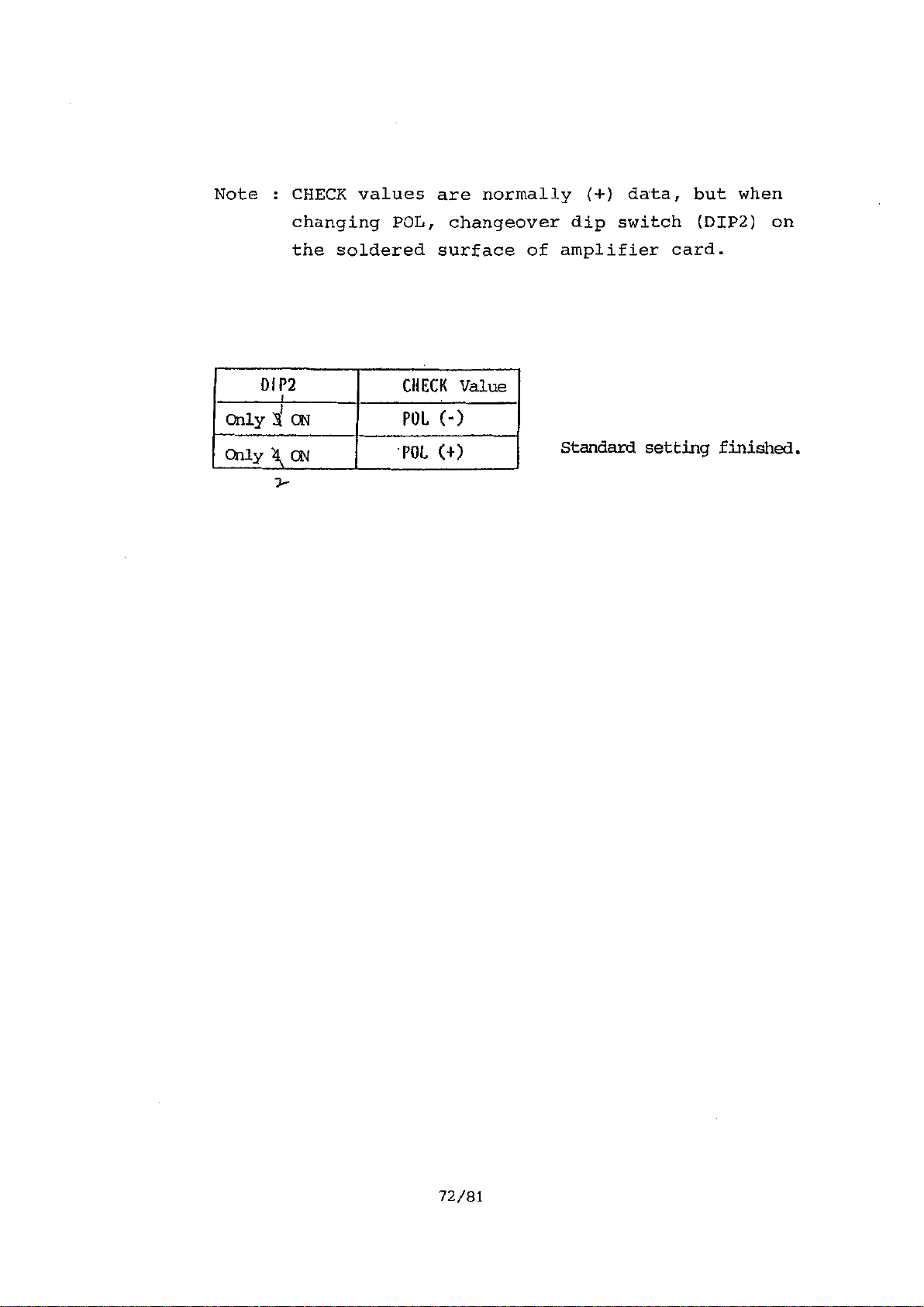
Note : CHECK values are normally (+) data, but when
changing POL, changeover dip switch (DIP2) on
the soldered surface of amplifier card.
D1P2
Only li ON
Only )4 ON
CHECK Value
POL (-)
'POL (+)
Standard setting finished.
72/81
Artisan Technology Group - Quality Instrumentation ... Guaranteed | (888) 88-SOURCE | www.artisantg.com
Page 79
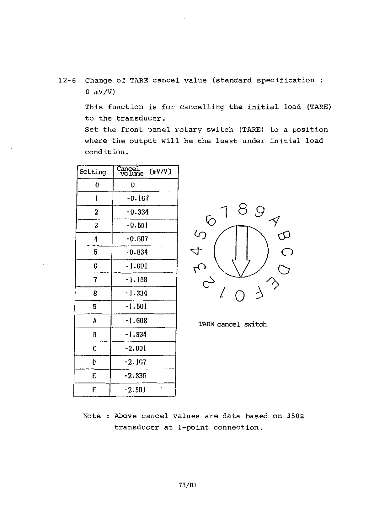
12-6 Change of TARE cancel value (standard specification :
0 mV/V)
This function is for cancelling the initial load (.TARE)
to the transducer.
Set the front panel rotary switch (TARE) to a position
where the output will be the least under initial load
condition.
Setting
0
1
2
3
4
5 -0.834
6
7
8
9
A -1.008
B
C -2.001
CETe ]. onv/v)
0
-0.107
-0.334
-0.501
-0.607
-1.001
-1.108
-1.334
-1.501
TARE cancel switch
-1.834
0
E
-2.167
-2.335
F -2.501
Note : Above cancel values are data based on 3502
transducer at 1-point connection.
73/81
Artisan Technology Group - Quality Instrumentation ... Guaranteed | (888) 88-SOURCE | www.artisantg.com
Page 80

Note : CHECK values are normally (-) data, but when
changing POL, changeover dip switch. (31132) on
the soldered surface of amplifier card.
01P2
Only 1 ON
Only 2 ON
CHECK value
POL (-)
POL (+)
Standard setting finished.
74/81
Artisan Technology Group - Quality Instrumentation ... Guaranteed | (888) 88-SOURCE | www.artisantg.com
Page 81

§13. SPECIFICATION
13-1 General specification
Analog section
Bridge voltage
DC10V +3%, within 150mA (Capable of 3V,
5V by DIP switch) attached with remote
sensing (capable of security response)
Signal input range
Number of load cell
connection
Maximum sensitivity
0.5mV/V ft, 3mV/V
Up to 4 sets of strain gauge type
converter (3500)
10V output at 0.5mV/V input (2000 times)
(provided that the bridge'voltage is 10V)
Output
+10V max. (more than 2K +S2 output
impedance)
4-20mA (option) (less than 5000 output
impedance)
GAIN
2000 times max. (8-steps adjustment by
the front panel rotary switch)
SPAN Adjust 1/1 1, 3/4 of F.S. by the front
(Gain fine adjustment) panel SPAN adjustment trimmer
TARE cancel
0 + approx. 2.5mV/V range to be
cancelled in 16 separations by the
front panel TARE cancellation switch.
ZERO
Nonlinearity
CHECK
Frequency
characteristic
Temper a t u re
characteristics
Approx. +0.1mV/V to be adjusted by the
front panel ZERO adjustment trimmer.
0.02% F.S .
Output by the front panel CHECK switch
ON, or by short of rear terminal board
CHECK terminal.
Adjusted to approx. 80% at the time of
shipment from the factory.
DC q, 1.5 Hz (-3dB)
ZERO +0.02pV/°C RTI
SPAN +0.01% reading/°C
75/81
Artisan Technology Group - Quality Instrumentation ... Guaranteed | (888) 88-SOURCE | www.artisantg.com
Page 82
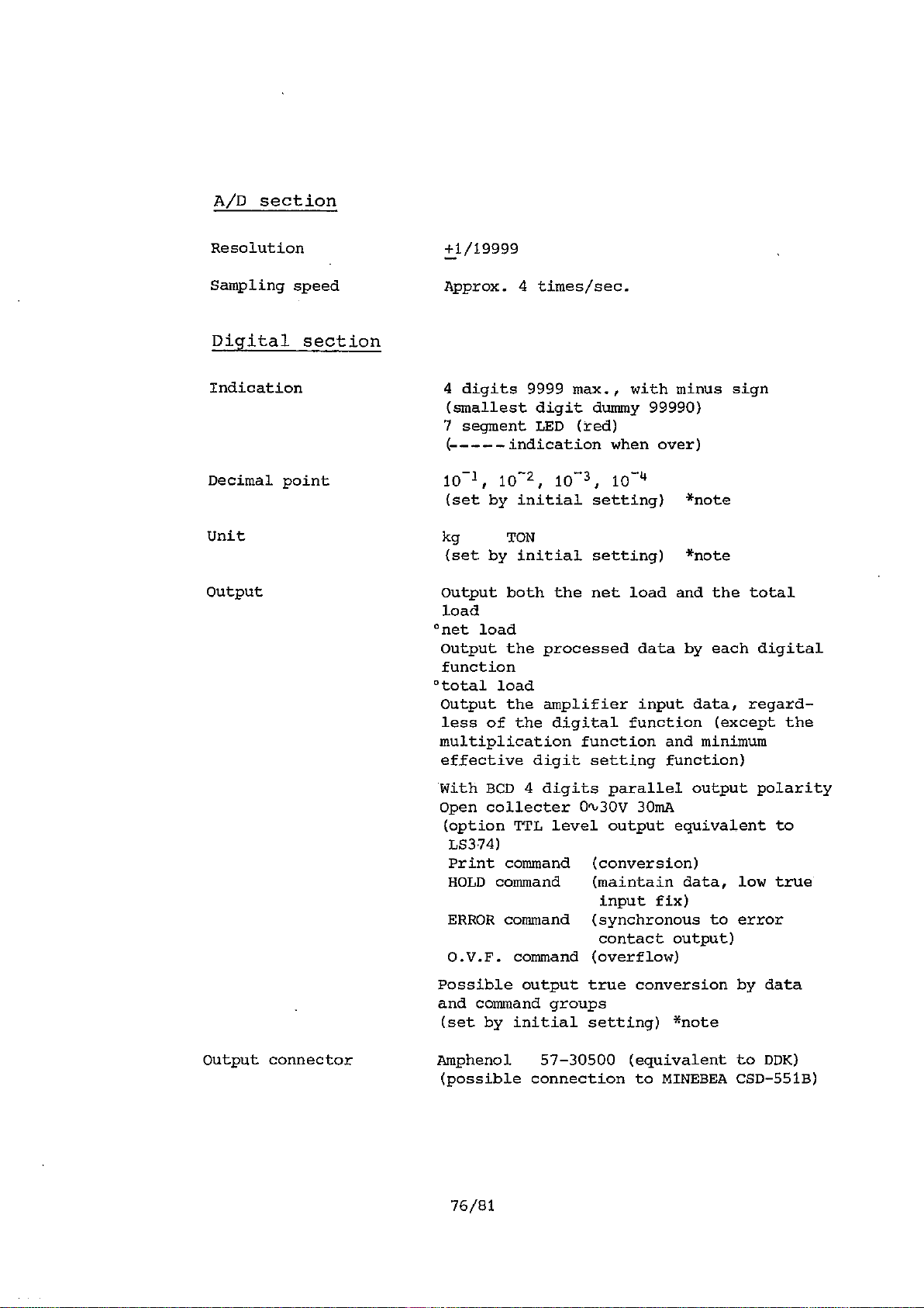
A/D section
Resolution
Sampling speed Approx. 4 times/sec.
+1/19999
Digital section
Indication
Decimal point 101, 10-2, 10-3, 10-4
Unit kg TON
Output Output both the net load and the total
4 digits 9999 max., with minus sign
(smallest digit dummy 99990)
7 segment LED (red)
(------ indication when over)
(set by initial setting) *note
(set by initial setting) *note
load
°net load
Output the processed data by each digital
function
°total load
Output the amplifier input data, regard-
less of the digital function (except the
multiplication function and minimum
effective digit setting function)
With BCD 4 digits parallel output polarity
Open collecter 04,30V 30mA
(option TTL level output equivalent to
LS374)
Print command (conversion)
HOLD command (maintain data, low true
input fix)
ERROR command (synchronous to error
contact output)
O.V.F. command (overflow)
Possible output true conversion by data
and command groups
(set by initial setting) *note
Output connector Amphenol 57-30500 (equivalent to DDK)
(possible connection to MINEBEA CSD-551B)
Artisan Technology Group - Quality Instrumentation ... Guaranteed | (888) 88-SOURCE | www.artisantg.com
Page 83
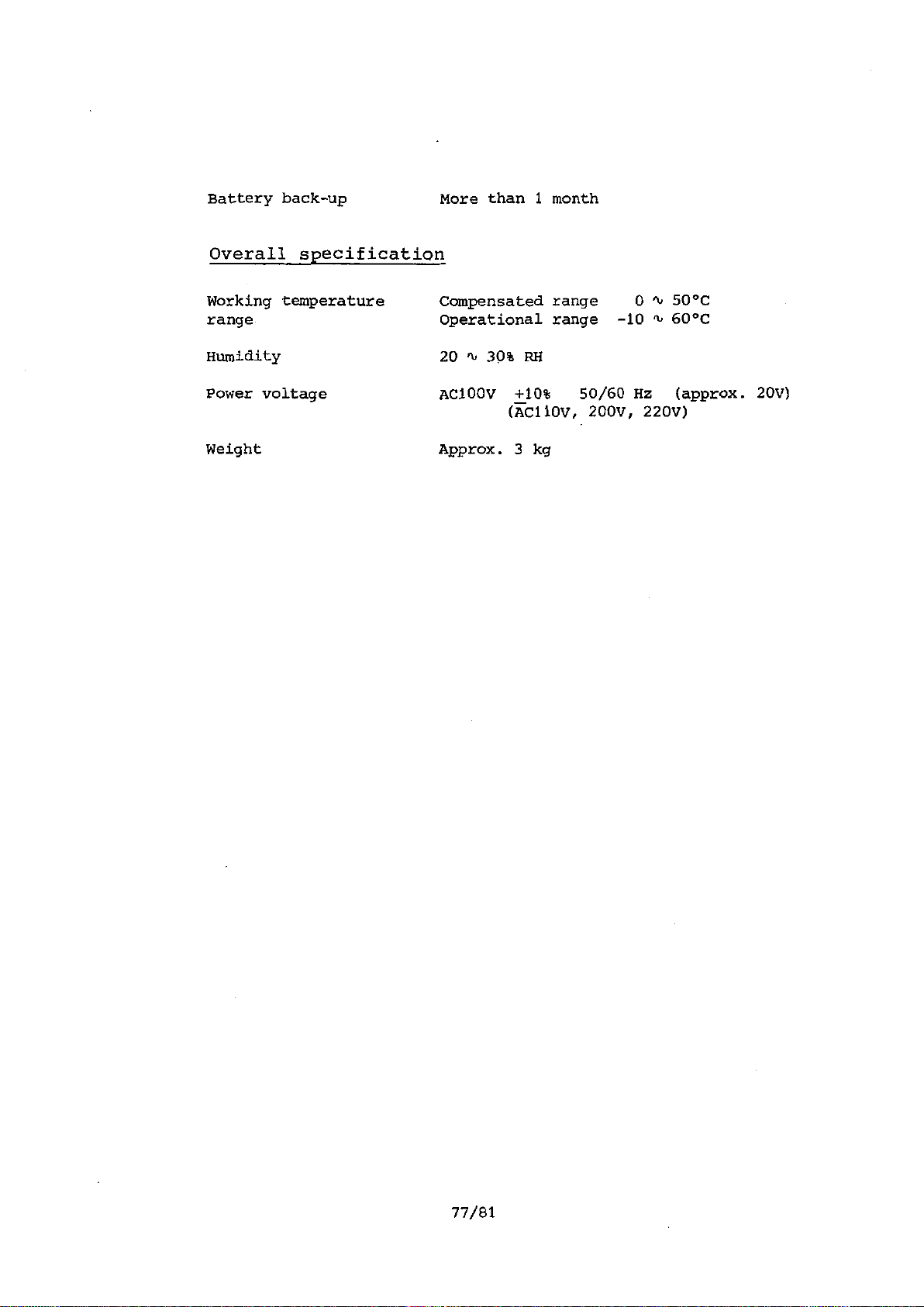
Battery back-up More than 1 month
Overall specification
Working temperature
range
Humidity
Power voltage
Compensated range 0 11, 50°C
Operational range -10 '10 60°C
20 '10 30% RH
AC100V +10% 50/60 Hz (approx. 20V)
(FAC110V, 200V, 220V)
Weight Approx. 3 kg
77/81
Artisan Technology Group - Quality Instrumentation ... Guaranteed | (888) 88-SOURCE | www.artisantg.com
Page 84

13-2 Block Diagram
(1) Amplifier section
INPUT
OUTPUT
CHOPPER AM P .
CHECK SW
TARE
HECK
ZERO Trimmer
voltage adjustment
FILTER
CM
CARD
4 SPAN Trimmer
G
A/D converte
V - OUT
F0
OUT
0
78/81
Artisan Technology Group - Quality Instrumentation ... Guaranteed | (888) 88-SOURCE | www.artisantg.com
Page 85

(2) Digital section
TO A/D
150 Hz
ROM
(27C256)
RAM
(6264)
BATT.
BACK UP
OSC. , 1
1.5MHz
RESET
CPU Z30
/e////,'
INT
<
PIO
PORT A
A/D DATA READ
STB FROM Ai/D
DISPLAY DATA
OUTPUT PORT
PORT B
KEY SWITCH
HOLD READ
79/81
AMP CARD
CONTROL PORT
DIG. SWITCH
READ PORT
CONTACT OUTPUT
PORT
BCD - OUT PORT
Artisan Technology Group - Quality Instrumentation ... Guaranteed | (888) 88-SOURCE | www.artisantg.com
Page 86

13-3 Appearance Drawing
•••I
o
leiontojejelJi.tnmgJ
—00-
0
illi.ic_litiiiisli12D:111'4E1i:77 7,..;
Q..0.0.0 riv„.
/56
/76
0
bribbtaLII.L=t
C
0 i ;Atb) ItITLIC*6t1
i•------.4.L.K
0
_0
-T777-7-1, ''` ,
CIFIR ClicirlFirliciwri
7
156
.
.4
0
0
•
0
,
....;
In case of nut lock,
prepare 04.5 hole.
Panel cut
4tV
/66
80/81
Artisan Technology Group - Quality Instrumentation ... Guaranteed | (888) 88-SOURCE | www.artisantg.com
Page 87

§14. ACCESSORIES
(1)
(3)
(4)
Fuse (05. x L20
Micro-driver
BCD-OUT connector (57-30500)
(5) Instruction manual (this book)
1A)
1
pc.
1
pc.
1
pc.
set
1
81/81
Artisan Technology Group - Quality Instrumentation ... Guaranteed | (888) 88-SOURCE | www.artisantg.com
Page 88

Artisan Technology Group - Quality Instrumentation ... Guaranteed | (888) 88-SOURCE | www.artisantg.com
Page 89

• The contents of this manual may subject to change without notice.
D The contents of this manual may subject to change without notice.
HEAD QUARTER : MINEBEA CO., LTD.
HEAD QUARTER : MINEBEA CO., LTD.
4106-73 Miyota, Miyota—machi, Kitasakugun, Nagano—ken 389-0293, Japan
4106−73 Miyota, Miyota−machi, Kitasakugun, Nagano−ken 389−0293, Japan
n0267-32-2200 FAx.0267-31— 1350
0267−32−2200 .0267−31−1350
Measuring Components Business Unit
Measuring Components Business Unit
FUJISAWA PLANT 1-1-1, Katase, Fujisawa—shi Kanagawa—ken, 251-8531 Japan
FUJISAWA PLANT 1−1−1, Katase, Fujisawa−shi Kanagawa−ken, 251−8531 Japan
n0466-22-7151 FAx. 046 6 —22 —1701
0466−22−7151 .0466−22−1701
KARUIZAWA PLANT 4106-73 Miyota, Miyota—machi, Kitasakugun, Nagano—ken 389-0293, Japan
KARUIZAWA PLANT 4106−73 Miyota, Miyota−machi, Kitasakugun, Nagano−ken 389−0293, Japan
n0267-31-1309 FAx.0267-31-13 50
0267−31−1309 .0267−31−1350
HOMEPAGE ADDRESS http://www.minebea-mcd.com
HOMEPAGE ADDRESS http://www.minebea−mcd.com
Artisan Technology Group - Quality Instrumentation ... Guaranteed | (888) 88-SOURCE | www.artisantg.com
Page 90

Artisan Technology Group is your source for quality
new and certied-used/pre-owned equipment
• FAST SHIPPING AND
DELIVERY
• TENS OF THOUSANDS OF
IN-STOCK ITEMS
• EQUIPMENT DEMOS
• HUNDREDS OF
MANUFACTURERS
SUPPORTED
• LEASING/MONTHLY
RENTALS
• ITAR CERTIFIED
SECURE ASSET SOLUTIONS
SERVICE CENTER REPAIRS
Experienced engineers and technicians on staff
at our full-service, in-house repair center
Instra
Remotely inspect equipment before purchasing with
our interactive website at www.instraview.com
Contact us: (888) 88-SOURCE | sales@artisantg.com | www.artisantg.com
SM
REMOTE INSPECTION
View
WE BUY USED EQUIPMENT
Sell your excess, underutilized, and idle used equipment
We also offer credit for buy-backs and trade-ins
www.artisantg.com/WeBuyEquipment
LOOKING FOR MORE INFORMATION?
Visit us on the web at www.artisantg.com for more
information on price quotations, drivers, technical
specications, manuals, and documentation
 Loading...