

Page 1
Digital Peak Holder
CSD-709
Start Guide
Thank you for choosing Digital Peak Holder CSD-709.
This start guide describes simply how to mount, wire, set, and operate CSD-709.
For further detailed information, please download the instruction manual from
our homepage.
From PC
http://www.minebea-mcd.com/en/product/i-amp/csd709.html
Accessories
(1) Unit sticker: 1 piece
(2) External control input/output connector:
1 piece
(3) Start guide (Japanese and English): 1 piece each
Safety Precautions
▼Safety Precautions
- Attach cables while power is NOT supplied to CSD-709
This unit is not equipped with a power ON/OFF switch.
Working with power supplied may cause electric shock or damage to CSD-709.
- The terminal block at the back of CSD-709 is made of resin.
Do not drop it or apply strong shock to it.
- Use shielded cables for all cables except power cable
. Keep CSD-709 away from noise sources such as a power supply line of peripheral equipment and
control I/O as much as possible.
- When a conduit is used for wiring, it should be dedicated for this unit.
Do not share a conduit with another line.
- Perform Class D grounding for this unit alone using the protective grounding terminal.
Grounding should not be shared with the power supply system.
* Be sure to read detailed information provided in the instruction manual.
▼Applicable Standard
EMC Directive (EN61326-1:2006)
“Electrical equipment for measurement, control and laboratory use – EMC requirements”
“Immunity test requirements for equipment intended for use in industrial location”Low Voltage
Directive (EN61010-1:2010)
“Safety requirements for electrical equipment for measurement, control, and laboratory use”
* To make CSD-709 compliant with this standard, the following use conditions need to be met.
- Cable: Use shielded cables for all cables except power cable.
- Shield processing: For the shield processing method, refer to the related sections.
Grounding: Ground this unit alone using the protective grounding terminal.
In this start guide, matters to be observed to avoid injury or accident,
instructions to maintain measurement accuracy, etc.,
and references for setting or operation are provided with mark.
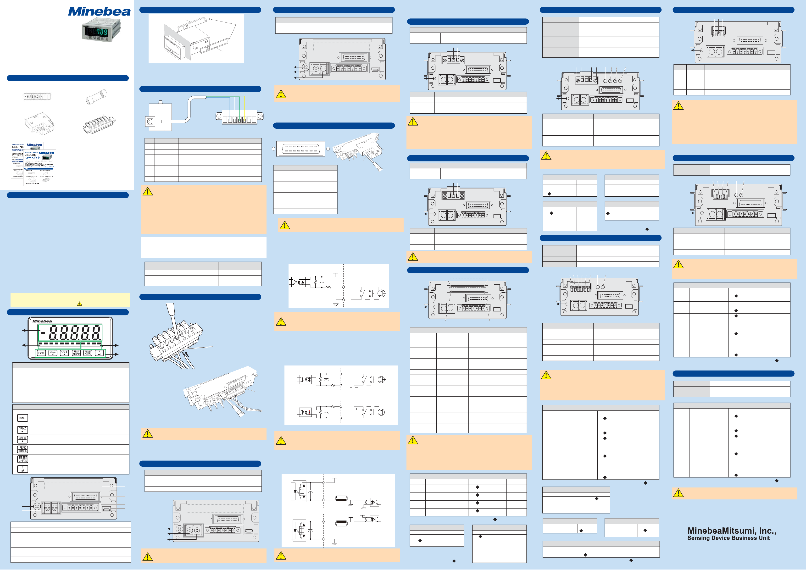
Names and Functions
(Front)
Load display
Status display
SEL1, SEL2
CHECK
HOLD
PEAK
MEAS
END
LOCK
SEL.1 SEL.2
Turns on according to the selected calibration number.
Turns on while CHECK value is output.
Turns on during hold.
Turns on during peak detection.
Turns on in non reset zones during peak detection.
Turns on while hold operation is performed during peak detection.
Turns on while keys are locked collectively.
Switches to a mode other than measurement mode,
such as function mode. Also, holding down this key more than
two seconds can execute simple numerical-input calibration.
Moves the cursol to the next digit. Also, holding down this key
more than two seconds can execute simple zero calibration.
ncreases the number of setting target by one. Also, holding down
this key more than two seconds can execute simple span calibration.
Switches between a tracking value and a peak detection.
Resets a peak value during peak detection or outputs a check value.
Executes a preset F key operation. It also confirms and registers
setting contents.
(Back)
(1)
(2)
(3) Connector for options
(4)
External control input/output connector
(5) Connector for strain gage based
transducer
CSD-709
CHECK HOLD
(4) Midget fuse: 1 piece (2.5 A)
(5) Connector for strain gage based transducer:
1 piece
Accessories for optional items
□ Voltage output plug (attached to CSD-709-29)
□ Current output plug (attached to CSD-709-07)
□ BCD output plug (attached to CSD-709-15/-16)
□ RS-232C plug (attached to CSD-709-74)
□ RS-422/485 plug (attached to CSD-709-76)
□ Serial interface plug (attached to CSD-709-77)
□ CC-Link plug (attached to CSD-709-73)
□ Application CD-ROM (attached to CSD-709-91)
□ USB cable (attached to CSD-709-91)
Digital Peak Holder
PEAK MEAS. END LOCK OUT1 OUT2 OUT3 OUT4
Status display
Keys
Connect a grounding wire.(1) Protective grounding terminal
Connect a power cable.(2) Power terminal block
Connect a cable according to the option
mounted.
Connect a cable according to the option mounted.
Connect the connector for strain gage type
transducer
Connect a USB cable.(6) USB interface connector
Judgment
display
Keys
How To Mount CSD-709 Option: Connecting DC Power Supply CSD-709-67 Option: CC-Link Card CSD-709-73 Option: Seiral I/F Card CSD-709-77
B
A
Screws
B
Panel mounting bracket
Panel
1. Remove two screws (A) at the back of CSD-709 and remove two panel mounting brackets (B) on
both sides.
2. Insert CSD-709 from the front of the panel.
3. Attach the panel mounting brackets (B) from the back of the panel and fix them with two screws (A).
Wiring the Connector for Strain Gage Based Transducer
3m
ABCDE+-
Load cell
Signal Description Cable color
+EXC
A
-SIG
B
-EXC
C
+SIG
D
SLD
E
MONI_OUT
+
MONI_GND
-
- The table shows Minebea’s standard signal cable colors.
Signal cables of a strain gage based transducer such as load cell are color-coded depending
on the manufacturer. Before connecting signal cables, check the manual or certificate of the
strain gage based transducer you use.
-
When you use a tension or compression/tension type load cell and use positive display for the
tension tensile direction, exchange +SIG (green) and –SIG (blue) cables and connect them.
- Keep the cable length between the junction box and this unit a maximum of 30 m.
If the cable is longer than 30 m, the input voltage to this unit drops due to resistance of the cable,
and the guaranteed accuracy may not be obtained.
- To comply with CE mark applicable standard,
connect the shield of the load cell cable to the protective grounding terminal.
The excitation voltage applied to this unit can be selected from those in the below table, and the number of
parallel-connected strain gage based transducers (350 Ω) and monitoring output are determined accordingly.
Do not short circuit the monitoring output and make the load resistance 2 kΩ or more.
Open the output when not used.
Excitation
DC2.5 V
DC5 V
DC10 V
Load cell excitation +
Load cell signal -
Load cell excitation -
Load cell signal +
Shield
Monitoring output (+)
Monitoring output (-)
Connectable units
in parallel
8
4
2
Monitoring output
(per sensor input of 1 mV/V)
Red
Blue
White
Green
Yellow
-
-
Approx. 0.5 V
Approx. 1 V
Approx. 2 V
Voltage
Consumption power
Back of CSD-709
Protective
grounding
terminal
+
-
- Check that power is NOT supplied to the cables.
- The polarity of power terminal is positive and negative from the left, facing the back of CSD-709.
Be sure to perform correct wiring.
External Control Input/Output
Connecting the External Control Input/Output Connector
Terminal block
A8 A7 A6 A5 A4 A3 A2 A1
B8 B7 B6 B5 B4 B3 B2 B1
Pin No. Pin No.Usage Usage
A1
INPUT1
A2
INPUT2
A3
INPUT3
A4
INPUT4
A5
INPUT5
A6
INPUT6
A7
A8
COM.1
- Non-voltage contact input type
For the external control input circuit, a non-voltage contact input type (standard) and voltage input type
(option) are available. With the non-voltage contact input type used, signals are input by causing a short
circuit/open between the input and COM1 terminals. To cause a short circuit, contact (relay, switch, etc.) or
non-contact (open collector output, etc.) is used.
Inside CSD-709
B1
B2
B3
B4
B5
B6
B7
B8
To comply with CE mark applicable standard, use a shielded cable and connect the shield
to the protective grounding terminal.
How To Wire
Wiring procedure
1. Peel off the covering of signal cable for a length
of 6 mm to 7 mm.
2. Insert a signal cable into a hole on the connector
(A) and tighten a screw on the top of the connector.
- To input signals using open collector output, use sink type (negative common) connection.
- With the non-voltage contact input type (standard) used, the internal power voltage is 12 VDC
and current at short circuit is approx. 5 mA.
- Option: Voltage input type CSD-709-44
A
B
B
3. Attach the connector to CSD-709 and tighten two screws (B) on both ends.
The connector of the same type used for each option is wired in the same manner.
Power Supply
Connecting AC Power Supply
Specifications
Voltage
(3)
(4)
(5)
(6)
Frequency
Power consumption
Back of CSD-709
Protective grounding
terminal
Check that power is NOT supplied to the cables.
100 VAC to 240 VAC
50/60 Hz
Approx. 10 W (at 100 VAC)
L
N
With the voltage input type used for external control input, signals are input by applying a voltage
between the input and COM1 terminals. At this time, contact (relay, switch, etc.) or non-contact
(transistor, etc.) is used with external power voltage to cause a short circuit and open. Either positive
common or negative common connection can be performed for the voltage input type.
To input signals using a transistor, use sink type for the positive common connection or source type for
the negative common connection. With the voltage input type used, the maximum rated voltage is 27.6
VDC, ON condition is 9 VDC or more (with 24 VDC external power voltage and approx. 10 mA load
current), and OFF condition is 3 VDC or less.
- Equivalent circuit of external control output
The external control output circuit is applied with photo MOS relay output.
Either positive common or negative common connection can be performed.
The following shows an equivalent circuit of external control output.
Inside CSD-709
Inside CSD-709
- In the external control output circuit, the maximum rated voltage is 30 VDC and the maximum rated
current is 100 mA per point.
Specifications
12 VDC to 24 VDC (10.6 VDC to 27.6 VDC)
Approx. 3.6 W (at 24 VDC)
A
OUTPUT1
OUTPUT2
OUTPUT3
OUTPUT4
OUTPUT5
How to mount
Attach the connector to CSD-709 and tighten two
screws (A) on both ends.
To check the connection, refer to
on the back page.
OUTPUT6
-
COM.2
+12 V
0.047 μ
470
2.2 k
Inside CSD-709
0.047 μ
430430
2.2 k
Surge removing element
Inside CSD-709
0.047 μ
0.047 μ
2.2 k
0.047 μ
+ Vext
COM2
Surge removing element
OUT 1 to 6
OUT 1 to 6
Surge removing element
COM2
Load
Load
IN 1
to
COM1
IN 1 to 6
COM1
DC12 V to 24 V
COM1
DC12 V to 24 V
IN 1 to 6
+ Vext
6
Positive common connection
Negative common connection
Positive common connection
+ Vext
Negative common connection
A
Check Mode
Option: Voltage Output Card CSD-709-29
Specifications
Output
Load resistance
Protective
grounding
terminal
±10 VDC
2 kΩ or more
123
Signal DescriptionPin No.
1
2
3
- Use a shielded cable for analog output and connect the shield to the F.G. terminal.
- To comply with CE mark applicable standard,
use a shielded cable and connect the shield to the protective grounding terminal.
- Insulated from the internal circuit via a photo coupler.
- Analog output has elements that fluctuate output after power-on.
For stable operation, leave CSD-709 for one hour or so after power-on before use.
- To check the connection, refer to
+
-
F.G.
Voltage output
Voltage output
Frame ground
Check Mode
on the back page.
Option: Current Output Card CSD-709-07
Specifications
Output
Load resistance
Protective
grounding
terminal
4 mA to 20 mA DC
510 Ω or less
123
Signal DescriptionPin No.
1
2
3
- Points to note are the same as those for the voltage output card. Check them.
- To check the connection, refer to
+
-
F.G.
Current output
Current output
Frame ground
Check Mode
on the back page.
Option: BCD Card CSD-709-15, -16
A1A16
Protective
grounding
terminal
B1B16
BCD output
Pin No.
Input/output
A1
A2
A3
A4
A5
A6
A7
A8
A9
A10
A11
A12
A13
A14
A15
A16
-
Output
Output
Output
Output
Output
Output
Output
Output
Output
Output
Input
Output
Output
Input
-
- Do not wire the N.C. pin.
- The COM.1 of external control input (standard) and COM. (sink type) of BCD output are shared.
- The COM.1 of external control input (standard) and 0V (source type) of BCD output are shared.
- Insulated from the internal circuit via a photo coupler.
- Output is turned OFF in the modes other than measurement mode.
- To comply with CE mark applicable standard, use a shielded cable and
connect the shield to the protective grounding terminal.
- To check the connection, refer to
BCD output logic (F-32): Set by 4-digit number
Digit Item Content Set value
1st digit
2nd digit
3rd digit
4th digit
Data output logic
Polarity output logic
Plug output logic
Print command output logic
BCD PC width (F-33)
Content
125 ms
25 ms
5 ms
Signal
COM. (sink type)
+24 V (source type)
1 x 100
4 x 100
1 x 101
4 x 101
1 x 10²
4 x 10²
1 x 10³
4 x 10³
1 x 10⁴
4 x 10⁴
SEL.1
POL.
ERROR
HOLD
N.C. (sink type)
0V (source type)
Check Mode on the back page.
Set value
0
1
2
Default is (0000).
Pin No.
Input/output
B1
B2
B3
B4
B5
B6
B7
B8
B9
B10
B11
B12
B13
B14
B15
B16
-
Output
Output
Output
Output
Output
Output
Output
Output
Output
Output
Input
Output
Output
Input
-
Negative logic
Positive logic
Negative logic
Positive logic
Negative logic
Positive logic
Negative logic
Positive logic
Default is (0000).
BCD output count (F-34)
Content
4 /s
20 /s
50 /s
100 /s
400 /s
1000 /s
4000 /s
Signal
COM. (sink type)
+24 V (source type)
2 x 100
8 x 100
2 x 101
8 x 101
2 x 10²
8 x 10²
2 x 10³
8 x 10³
2 x 10⁴
8 x 10⁴
SEL.2
OVER
P.C.
BCD-ENABLE
N.C. (sink type)
0V (source type)
0
1
0
1
0
1
0
1
Set value
0
1
2
3
4
5
6
CC-Link version
Connectable number
of units
Ver.1.10
Maximum of 64 units with one station occupied
Maximum of 32 units with two stations occupied
Maximum of 16 units with four stations occupied
Connected cable
Termination resistor
Use a cable dedicated for CC-Link.
External resistor
Status LED Show communication status with four LEDs
(RUN, SD, RD and ERROR).
RUN SD RD ERR
51234
Protective
grounding
terminal
Signal DescriptionPin No.
1
2
3
4
5
- Connect a termination resistor to the CC-Link connector farthest from PLC.
- Use a cable dedicated for CC-Link for connection.
- For the communication speed and cable length, refer to“Construction and specifications of network
system” of the latest version of “CC-Link Cable Wiring Manual” issued by CC-Link Partner Association.
DA
DB
DG
SLD
F.G.
CC-Link occupying stations (F-84)
Content Set value
1 station
2 stations
4 stations
CC-Link baud rate (F-86)
Content Set value
156 kbps
625 kbps
2.5 Mbps
5 Mbps
10 Mbps
Signal cable DA side
Signal cable DB side
Signal cable ground
Shield
Frame ground
0
1
2
0
1
2
3
4
CC-Link station No. (F-85)
Set value
01 to 64
1 station
CC-Link 32-bit data expression method (F-87)
Content Set value
Standard binary expression
Most significant bit sign01
Default is (0000).
Option: RS422/485 Card CSD-709-76
Transmission data
Cable length
Connected units
Termination resistor
Protective
grounding
terminal
1
2
3
4
5
6
- When multiple units are connected,
cause a short circuit between the TRM. and RDB terminals on CSD-709 farthest from the host
(personal computer, sequencer, etc.) and connect the internal termination resistor.
- The COM.1 of external control input (standard) and S.G. of RS-422/485 are shared.
- Insulated from the internal circuit via a photo coupler.
- To comply with CE mark applicable standard, use a shielded cable and connect the shield
to the protective grounding terminal.
Communication setting (F-47): Set by 5-digit number
Digit Item Content
1st digit
2nd digit
3rd digit
4th digit
5th digit
Data bit length
Parity bit
Stop bit
Baud rate
Terminator
Operation mode (F-45)
Content Set value
Command mode
Stream mode
Print command synchronization
Modbus interface
Address setting (F-50)
Content Set value
RS-422/485 ID setting
Reply data delay time for RS-485 (F-52)
ASCII code
Approx. 1km
Maximum of 32 units (RS-422: 10 units)
Included (presence selected by terminal block connection)
RXD TXD
561234
Signal DescriptionPin No.
SDA
SDB
RDA
RDB
TRM.
S.G.
Differential output (+)
Differential output (-)
Differential output (+)
Differential output (-)
Termination resistor
Signal ground
Set value
7bit
8bit
No parity
Even parity
Odd parity
1bit
2bit
1200 bps
2400 bps
4800 bps
9600 bps
19200 bps
38400 bps
57600 bps
115200 bps
CR
CR+LF
Default is (13020).
0
1
2
3
RS-422/485 switching (F-51)
Content Set value
00 to 31
RS-422
RS-485
Set value
0 to 99 (unit: 10ms)
indicates a default.
Protective
grounding
terminal
Signal DescriptionPin No.
1
Serial I/F+
2
Serial I/F-
3
F.G.
- As the equipment supporting two-wire serial interface,
the printer M252B manufactured by Unipulse Corporation can be used.
- Use a two-core, shielded cable and connect the shield to the F.G. terminal.
- Twist a cable when a shield is not used.
(Cable length should be a maximum of 100 m with a shield or a maximum of 20 m without a shield.)
- Up to around three units of two-wire serial interface supporting equipment can be connected in parallel.
(Maximum output power: Approx. 20 mA DC)
- Insulated from the internal circuit via a photo coupler.
- To comply with CE mark applicable standard, use a shielded cable and connect the shield
to the protective grounding terminal.
Option: RS232 Card CSD-709-74
Transmission data
Cable length
Protective
grounding
terminal
1
2
3
4
- The COM.1 of external control input (standard) and S.G. of RS-232C are shared.
- Insulated from the internal circuit via a photo coupler.
-
To comply with CE mark applicable standard, use a shielded cable and connect the shield
to the protective grounding terminal.
Communication setting (F-47): Set by 5-digit number
Digit Item Content
1st digit
2nd digit
3rd digit
4th digit
5th digit
Data bit length
Parity bit
Stop bit
Baud rate
Terminator
Communication via USB
Output connector
Communication data
Address
Communication setting (F-47): Set by 5-digit number
Digit Item Content
0
1
0
1
2
0
1
0
1
2
3
4
5
6
7
0
1
1st digit
2nd digit
3rd digit
4th digit
5th digit
Data bit length
Parity bit
Stop bit
Baud rate
Terminator
- To use a USB interface, a dedicated driver needs to be installed on a host PC.
- Optional EzCTS and memory option are required for USB communication.
0
1
1-1-1, Katase, Fujisawa-shi Kanagawa-ken, 251-8531 Japan
Fujisawa Plant
http://www.minebea-mcd.com/en/
Interface
123
Connect the serial interface terminal (+) of the device to be
connected.
Connect the serial interface terminal (-) of the device to be
connected.
Frame ground
ASCII code
15 m or less
1234
RXD TXD
Signal DescriptionPin No.
DTR
TXD
RXD
S.G.
Data terminal ready
Transmission data
Reception data
Signal ground
Set value
7 bit
8 bit
No parity
Even parity
Odd parity
1 bit
2 bit
1200 bps
2400 bps
4800 bps
9600 bps
19200 bps
38400 bps
57600 bps
115200 bps
CR
CR+LF
0
1
0
1
2
0
1
0
1
2
3
4
5
6
7
0
1
Default is (13020).
miniUSB connector B type
ASCII code
00 (fixed)
Set value
7 bit
8 bit
No parity
Even parity
Odd parity
1 bit
2 bit
1200 bps
2400 bps
4800 bps
9600 bps
19200 bps
38400 bps
57600 bps
115200 bps
CR
CR+LF
0
1
0
1
2
0
1
0
1
2
3
4
5
6
7
0
1
Default is (13020).
TEL +81-466-22-7151 / FAX +81-466-22-1701
294-1768
Page 2
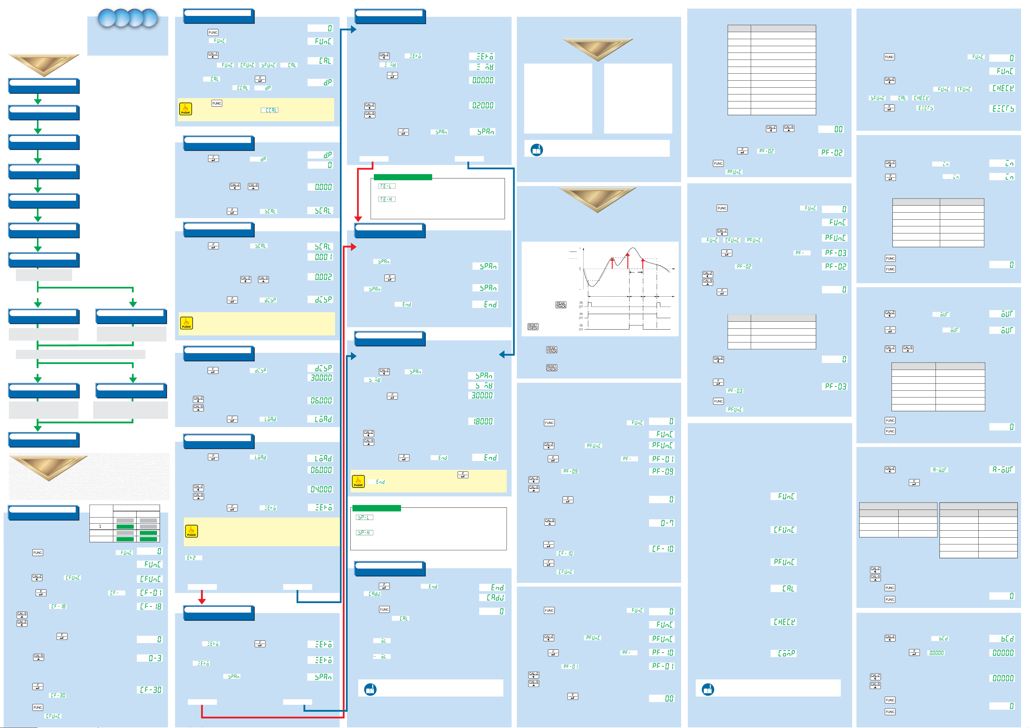
Calibration
Calibration
S
LED
SEL1
SEL2
Cal
ibr
ati
on
n
0
Reference
Reference
(1) Selecting Detection Condition Number
(3) Setting Detection Zone
● Checking External Control Input
● Checking External Control Output
● Checking Analog Output
● Checking BCD Output
(2) Setting Detection Operation
Reference
Calibration
Procedure
Calibration
Procedure
Detection Types
Detailed Detection Procedure
Detailed
Calibration
Procedure
Calibration
Procedure
Detection Procedure Detection Procedure Detection Procedure Detection Procedure
Check Mode Check Mode Check Mode Check Mode
ModesModesModesModes
Calibration
Procedure
Calibration
Procedure
Advanced preparation
Energizing power supply
(1)
Selecting Calibration Number
(2)
Input a power of 100 VAC to 240 VAC and frequency of
50/60 Hz (or 12 VDC to 24 VDC) and energize CSD-709 for
ten minutes or so to stabilize CSD-709 and measuring part
(load cell).
CSD-709 can retain four patterns of calibration result.
Select a calibration number to calibrate.
Switch from measurement mode to calibration mode.
The calibration is an operation that matches the
actual load of the sensor to the display of
CSD-709 to display the electrical signal from the
sensor (load cell) as an accurate load.
Switching to Calibration Mode
(3)
Set of Decimal Point Position
(4)
Set of Minimum Scale
(5)
Set of Rated Capacity
(6)
Set of Actual Load
Is it possible to create no-load state
(initial state)?
Yes No
(7) (7)
Zero Calibration (Actual Load)
Read a load cell output value in no-load state
and register a zero point.
Is it possible to apply a load two-thirds or more of the rated capacity?
Yes No
(8) (8)
Span Calibration (Actual Load)
Read a load cell output value while the load set
according to (6) Set of Actual Load is applied
and register a span point.
(9)
End of Calibration
Set the decimal point display position.
Setting range: [0 (None)], [0.0], [0.00], [0.000], and [0.0000]
Set the minimum scale (minimum unit for measurement).
Setting range: [1], [2], [5], and [10]
Set the rated capacity (maximum load that can be
measured).
Set the load actually applied in span calibration.
To minimize calibration error, use a load at least two-thirds
of the rated capacity.
If a load cannot be applied, input the same value as the rated
capacity.
Zero Calibration (Numerical Input)
When no-load state (initial state) cannot be created,
register the output [mV/V] equivalent to no-load
state by numerical input.
Span Calibration (Numerical Input)
Register a span point [mV/V] obtained by subtracting the output
[mV/V] equivalent to no-load stat e from the output [mV/V] equivalent
to the load equal to the rated capacity by numerical input.
Exit the calibration mode.
(2)
Switching to Calibration Mode
(1) Press the [***] key in the normal measurement mode
to display [xxx] .
(2) Press the [***] key three times. The display changes in the
following order: [xxx] -> [xxx] -> [xxx] -> [xxx] .
(3) When [CAL] is displayed, press the [***] key twice.
The display changes from [xxx] to [xxx] .
■
When the [***] key is pressed after taking the steps in (2) Switching to Calibration Mode,
the previous set value will be canceled and [xxx] will return on the display.
When you cancel the process halfway, the set value will not be saved.
(3)
(Measurement mode)
Setting Decimal Point Position
(1) When the [***] key is pressed while [xxx] is displayed,
a decimal point is displayed at the currently stored position.
(2) Set the position of decimal point.
Select the position using [***] and [***] keys.
The position of decimal point can be selected from [0 (None)], [0.0], [0.00],
[0.000], and [0.0000].
(3) After setting, press the [***] key to display [xx] .
(4)
Setting Minimum Scale
(1) When the [***] key is pressed while [xxx] is displayed,
the currently stored minimum scale is displayed.
(2) Set the minimum scale.
Select the minimum scale using [***] and [***] keys.
The last two digits change as follows: [01], [02], [05], and [10].
(3) After setting, press the [***] key to display [xxx] .
Example of display change caused by minimum scale setting
■
With the minimum scale set to [02], the load display changes as follows: [0.002] -> [0.004]
-> [0.006] (decimal point set to [0.000]).
(5)
Setting Rated Capacity
(1) When the [***] key is pressed while [xxx] is displayed,
the currently stored rated capacity is displayed.
(2) Set the rated capacity.
: Select a digit to change.
: Change the value of the selected digit.
(3) After setting, press the [***] key to display [xxx] .
Stored rated capacity
Set rated capacity
(6)
Setting Actual Load
Stored position
Set position
Stored position
Set position
(7)
Zero Calibration (Numerical Input)
Detection Procedure
Only when CSD-709 in use is replaced with another CSD-709 and also
all the following conditions are met, zero calibration is performed with numerical input.
- Zero calibration data (mV/V value) obtained before replacement remains.
- No-load state (initial state) cannot be created.
(1) Press the [***] key while [Zero] is displayed
to display [xxx] .
(2) Then press the [***] key to display the stored load cell output value.
Stored load cell output value
(3) Set the output value equivalent to no-load state in mV/V.
: Select a digit to change.
: Change the value of the selected digit.
(4) After setting, press the [***] key to display [xxx] .
Proceed to span calibration.
Is it possible to apply a load two-thirds or more of the rated capacity?
Yes No
Set load cell output value
mV/V
mV/V
Detection Types
Detection operation Detection zone
- Peak hold
- Bottom hold
- Peak/bottom hold
- Peak-to-peak hold
- Maximum value hold
- Minimum value hold
- Maximum-minimum difference hold
- Average value hold
- 4-inflection points hold
Reference
For detailed information,
refer to the instruction manual which can be found on our website.
- All zones
- Specified zone
- Time specified zone
- Automatic start time specified zone
http://www.minebea-mcd.com/en/
Zero calibration error display
This blinks for about two seconds when the load cell output exceeds
the zero adjustment range of negative side(-2.5 mV/V or less).
This blinks for about two seconds when the load cell output exceeds
the zero adjustment range of positive side(2.5 mV/V or more).
* To prevent the zero point from exceeding the adjustment range,
check the rated capacity of load cell, initial state, etc.
(8)
Span Calibration (Actual Load)
Read a load cell output value while the actual load set according to
(6) Setting Actual Load is applied and register a span point.
(1) While [xxx] is displayed,
apply the load set according to (6) Setting Actual Load
and press the [***] key
(2) [xxx] starts blinking and reading starts.
(3) When reading ends, [xxx] appears.
Proceed to
(9)
Blinks
(8)
Span Calibration (Numerical Input)
Register a span point by inputting a value obtained by subtracting the load cell output value at
the zero point from the load cell output value expected when the load equal to the rated
capacity is applied.
(1) Press the [***] key while [xxx] is displayed to display
kg
kg
[ .
(2) Then press the [***] key to display the stored load cell output
value.
(3) Set a value obtained by subtracting the output value equivalent
to the zero point of load cell from the load cell output
value equivalent to the set rated capacity in mV/V.
: Select a digit to change.
: Change the value of the selected digit.
Stored load cell output value
Set load cell output value
mV/V
mV/V
product/i-amp/csd709.html
Detailed Detection Procedure
Detection operation: Peak hold (hold a detected maximum load)
Detection zone: All zones The following describes the case using above conditions.
Actual load
Displayed value
Time
0
Load
Detection
Detection zone (1)
key
PEAK/TRACK input
key or RESET input
ON: Detects and displays a peak value. (Detection zone (1))
OFF: Displays the current load. (Load display zone)
During peak detection
ON: Displays 0. (RESET zone)
OFF: Resumes peak value detection. (Detection zone (2))
(1) Selecting Detection Condition Number
This unit can retain up to eight detection conditions using the detection condition numbers 0 to 7.
The following describes the setting procedure.
(1) Press the [***] key in the normal measurement mode to display [xxx] .
(2) Press the [***] key twice to display [xxx] .
RESET
zone
display
zone (2)
zone
(Measurement mode)
Detection operation numbers and corresponding detection operations
Detection operationNo.
00
Peak
Bottom
01
Peak/bottom
02
Peak-to-peak
03
Minimum value
04
Maximum value
05
Maximum-minimum difference
06
Inflection point A
07
Inflection point B
08
Inflection point C
09
Inflection point D
10
Average value
11
(6) Display the detection operation number using [***] and [***] keys.
* As an example,
[00] is selected to set the detection operation to peak hold.
(7) After displaying, press the [***] key. [xxx] appears.
(8) Press the [***] key twice to return to the measurement mode.
The display shows [xxx] and then the measurement mode returns.
(3) Setting Detection Zone
(1) Press the [***] key in the normal measurement mode to display [xxx] .
(2) Press the [***] key twice. The display changes in the following order:
[xxx] -> [xxx] -> [xxx] .
(3) Pressing the [***] key displays a two-digit number following [xxx] .
(4) Change the display to [xxx] .
: Select a digit to change.
: Change the value of the selected digit.
(5) Press the [***] key.
The current detection zone number will be displayed.
Stored detection
zone number
Detection zone numbers and corresponding detection zones
Detection zoneNo.
0
All zones
1
Specified zone
2
Time specified zone
3
Automatic start time specified zone
(6) Press the [***] key and
select the number corresponding to desired detection zone
* As an example, [0] is selected to set the detection zone to all zones.
(7) Press the [***] key to confirm the detection zone.
The display shows [xxx] .
(8) Press the [***] key twice to return to the measurement mode.
The display shows [xxx] and then the measurement mode returns.
Modes
Check Mode
Switching to Check Mode
This unit allows the user to check various items via check mode.
(1) Press the [***] key in the normal measurement mode to display [xxx] .
(Measurement mode)
(2) Press the [***] key four times.
The display changes in the following order: [xxx] -> [xxx] ->
[xxx] -> [xxx] -> [xxx] .
(3) Press the [***] key to display [xxx] .
Select an item to check from the following items and take the procedure.
● Checking External Control Input
(1) Press the [***] key four timesto display [xxx] .
(2) When the [***] key is pressed after displaying, [xxx] blinks and
the LED corresponding to the external control input turns on.
External control input LED name
INPUT1 turns ON
INPUT2 turns ON
INPUT3 turns ON
INPUT4 turns ON
INPUT5 turns ON
INPUT6 turns ON
(3) Press the [***] key to complete the check of external control input.
(4) Press the [***] key twice to return to the measurement mode.
● Checking External Control Output
(1) Press the [***] key five times to display [xxx] .
(2) When the [***] key is pressed after displaying, [xxx] blinks and
the LED “OUT1” at the status display turns on.
(3) Using the [***] and [***] keys, turn on the followingLEDs to turn on
the corresponding external control outputs.
SEL1
SEL2
CHECK
HOLD
PEAK
MEAS.
External control outputLED name
OUT1
OUT2
OUT3
OUT4
SEL1
SEL2
(4) Press the [***] key to complete the check of external control output.
(5) Press the [***] key twice to return to the measurement mode.
OUTPUT1 turns ON
OUTPUT2 turns ON
OUTPUT3 turns ON
OUTPUT4 turns ON
OUTPUT5 turns ON
OUTPUT6 turns ON
Blinks
(Measurement mode)
Blinks
(Measurement mode)
Calibration with actual load assumes
Detailed
Calibration
Procedure
(1)
Selecting Calibration Number
This unit can retain calibration results using four
calibration numbers: 0 to 3.
The LED ON/OFF state at the status display
indicates the current calibration number.
(1) Press the [***] key in the normal measurement mode to display [xxx] .
(2) Press the [***] key to display [xxx] .
(3) Pressing the [***] key displays a two-digit number following [xxx] .
(4) Change the display to [xxx] .
: Select a digit to change.
: Change the value of the selected digit.
(5) After displaying, press the [***] key.
The current calibration number (0 to 3) appears.
(6) Press the [***] key to select a calibration number with which you want to
save the calibration result. A calibration number changes
in the following order: [0] -> [1] -> [2] -> [3].
(7) Press the [***] key to confirm the calibration number.
The display becomes [xxx] .
(8) Press the [***] key twice to return to the measurement mode.
The display shows [xxx] and then it returns to the measurement mode.
Calibration with actual load assumes a rated capacity
of 6.000 kg in the state where a load of 4 kg can be
applied and a minimum scale of 0.002 kg.
Calibration with numerical input assumes
Calibration with numerical input assumes 0.2 mV/V as
the output equivalent to no-load state (initial state) and
2 mV/V as the output equivalent to the rated capacity.
Calibration
number
umber
0
1
2
3
Status display LED
tatus display
SEL1 SEL2
(Measurement mode)
Set calibration number
Proceed to step
(2)
(1) When the [***] key is pressed while [xxx] is displayed,
the currently stored actual load is displayed.
(2) Set the actual load value.
: Select a digit to change.
: Change the value of the selected digit.
(3) After setting, press the [***] key to display [xxx] .
■
Set the actual load value used for calibration to a value at least two-thirds of the rated capacity.
■
When the load which is the same as the rated capacity can be applied, set the actual load
equal to the rated capacity.
■
When span calibration is performed with numerical input according to (8) Span Calibration
(Numerical Input), set the actual load equal to the rated capacity.
Error display in rated capacity/actual load setting
* Correct settings so that “Rated capacity ≥ Actual load” is met.
This blinks for about two seconds when you set a value meeting [Rated capacity] < [Actual load].
Proceed to zero calibration.
Is it possible to create no-load state (initial state)?
Yes No
(7)
Zero Calibration (Actual Load)
Read a load cell output value in no-load state (initial state) and
register a zero point.
(1) While [xxx] is displayed, press the [***] key
without applying a load.
(2) [xxx] starts blinking and reading starts.
(3) When reading ends, [xxx] appears.
Proceed to span calibration.
Is it possible to apply a load two-thirds or more of the rated capacity?
Yes No
Stored actual load
Set actual load
Blinks
(4) After setting, press the [***] key to display [End] .
kg
kg
■
A set value remains in provisionally-registered state until the [***] key is pressed with
[xxx] displayed to confirm the value. When you cancel the process halfway,
the set value will not be saved.
Span calibration error display
* To prevent the span point from exceeding the adjustment range,
check the rated capacity of load cell, actual load, etc.
This blinks for about two seconds when the load cell output falls short of the span
adjustment range(Load cell output voltage at span point - Load cell output voltage at
zero point ≤ 0.0 mV/V).
This blinks for about two seconds when the load cell output exceeds the span
adjustment range(larger than 3.1 mV/V).
(9)
End of Calibration
(1) When the [***] key is pressed while [End] is displayed,
[xxx] appears and the set data is stored in the internal memory.
(2) Press the [***] key twice to return to the measurement mode.
The display shows [CAL] and then the measurement mode returns.
Measurement error display
* To display an overload error, any of the following conditions can be set.
When the load display
- exceeds “(+ Rated capacity) + 9 divisions”
- exceeds “+110 % of rated capacity”
When the load display
- falls below “(- Rated capacity) - 9 divisions”
- falls below “-110 % of rated capacity”
- falls below “-20 divisions”
Reference
For detailed information,
refer to the instruction manual which can be found on our website.
(Measurement mode)
http://www.minebea-mcd.com/en/
(3) Pressing the [***] key displays a two-digit number following [xxx] .
(4) Change the display to [xxx] .
: Select a digit to change.
: Change the value of the selected digit.
(5) After setting, press the [***] key.
The current detection condition number (0 to 7) will be displayed.
(6) Press the [***] key to select a detection condition number you want to save.
A calibration number changes in the following order: [0] -> [1] -> [2] ... [7].
(7) Press the [***] key to confirm the detection condition number.
The display shows [xxx] .
(8) Press the [***] key twice to return to the measurement mode.
The display shows [xxx] and then the measurement mode returns.
(2) Setting Detection Operation
(1) Press the [***] key in the normal measurement mode to display [xxx] .
(2) Press the [***] key twice to display [xxx] .
(3) Pressing the [***] key displays a two-digit number following [xxx] .
(4) Change the display to [xxx] .
: Select a digit to change.
: Change the value of the selected digit.
(5) After displaying, press the [***] key.
The current detection operation number will be displayed.
Stored detection
condition number
Set detection
condition number
(Measurement mode)
Stored detection
operation number
product/i-amp/csd709.html
The following modes are used to perform measurement or operate CSD-709.
Measurement mode
Displays the current measurement value. The measurement mode is divided into two modes.
- Tracking mode: Displays an input value from measuring instrument which varies with time.
- Peak mode: Detects and retains a maximum/minimum point, etc. in measurement values.
Function mode
Allows the user to set the following functions or check the setting contents.
- Measurement function (AD sampling count, digital filter, etc.)
- Comparison function (comparator operation, etc.)
- Operation function (key lock, hold target, etc.)
C function mode
Allows the user to set the following functions or check the setting contents.
- Calibration number selection
- Decimal point display position
- Current calibration data, etc.
P function mode
Allows the user to set the following functions or check the setting contents.
- Detection zone
- Detection operation, etc.
CAL selection mode
This mode is divided into the following four modes.
- CCAL mode: Calibration
- CADJ mode: Fine adjustment of calibration results
- VCAL/VADJ mode: Calibration or adjustment for options such as current/voltage output card
CHECK mode
Used to check the following items.
- ROM version of CSD-709
- Mounted options
- Externally controlled operation, etc.
COMP selection mode
Used to check the following items.
- Comparison value setting contents
- Setting contents related to the comparator, etc.
Reference
For detailed information,
refer to the instruction manual which can be found on our website.
http://www.minebea-mcd.com/en/
product/i-amp/csd709.html
● Checking Analog Output
(1) Press the [***] key six times to display [xxx] .
(2) After displaying, press the [***] key.
As shown in the tables, the display varies
depending on the mounted card and output value.
Current output card
DisplayOutput value
4 mA
12 mA
20 mA
(3) Change the current or voltage value to be output.
: Change the sign
: Change the display.
(4) Press the [***] key to complete the check of analog output.
(5) Press the [***] key twice to return to the measurement mode.
● Checking BCD Output
(1) Press the [***] key six times to display [xxx] .
(2) After displaying, press the [***] key. [xxx] appears.
* “0” on the first digit blinks.
(3) Change the digit of blinking “0”.
: Blinking digit moves toward the smallest digit.
: Blinking digit moves toward the largest digit.
(4) Press the [***] key to complete the check of BCD output.
(5) Press the [***] key twice
to return to the measurement mode.
LOW
MID
HI
0 V
10 V
-5 V
-10 V
Voltage output card
DisplayOutput value
LOW
5 V
0 V
MID
HI
-LOW
-MID
-HI
(Measurement mode)
(Measurement mode)
Blinks
 Loading...