

Page 1
MINEBEA CO., LTD.
INSTRUCTION MANUAL
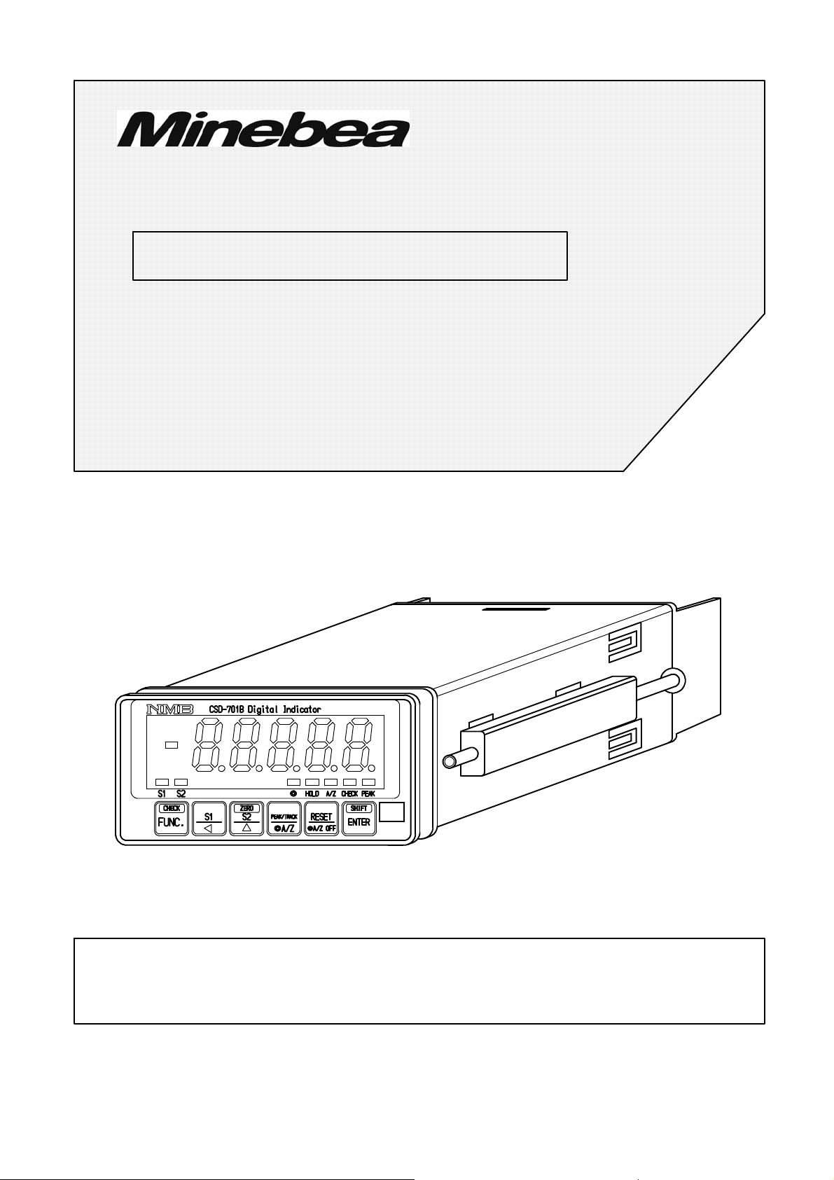
DIGITAL INDICATOR
CSD−701B
Note : Please read this Instruction Manual carefully before use.
Be sure to follow the items that require attention described in the manual.
Keep the manual at hand so that you can pick it up and read it as soon as
necessity requires.
EN294−1127−K
Page 2

Forwards
Thank you very much for your purchasing Minebea’s Digital Indicator CSD−701B.
This manual explains installation procedures and connecting method and also operating
method for the Digital Indicator CSD−701B. Make use of it properly after reading through
the manual carefully.
Be sure to deliver the manual to the end user. Moreover, the end user should keep the
manual at hand after reading it over.
This manual is intended for the technical experts to read.
●The contents of the manual may subject to change for improvement without notice.
I
Page 3
Marks and arrangements used in this manual
The following marks are attached to the explanation on the matters that indicate “Don’t do
this.”, “Take care.” and “For reference”.
Be sure to read these items where these marks are attached.
Warning ● Warning may cause injury or accident that may harm to the operator.
Don’t do these things described here.
● Caution during operation and working.
Be sure to read the item to prevent malfunction.
Mark during operation.
● Press the switch.
II
Page 4

For safe operation
Be sure to read this instruction manual before use.
1. Installation place
● Use the instrument where the temperature/humidity specifies with
the range as follows:
Environmental temperature :−10 ℃ to 50 ℃
Environmental humidity :Less than 85 %R.H. (Non condensing)
(1) Location where installation is not allowed.
Warning ● Don’t locate the instrument on the places as follows :
It may cause an unexpected faulty in the instrument.
・ Don’t locate the instrument in direct and/or high temperature area.
・ Don’t use the instrument in a high humid area.
・ Don’t install the instrument where there are vibrations and shocks.
・ Don’t use the instrument where there is excess of dusts and fine particles.
・ Don’t use the instrument where there are corrosive gas and salt and like
that.
・ Don’t install the instrument where there is rapid change of temperature
and humidity.
・ Don’t install the instrument near the devices that are magnetized or
generate an electromagnetic field.
・ Don’t install the instrument where the instrument may be affected by
radioactivity or radial rays.
・ Avoid the location where chemical reaction may take place such as in a
laboratory, or like that.
III
Page 5
(2) Installation
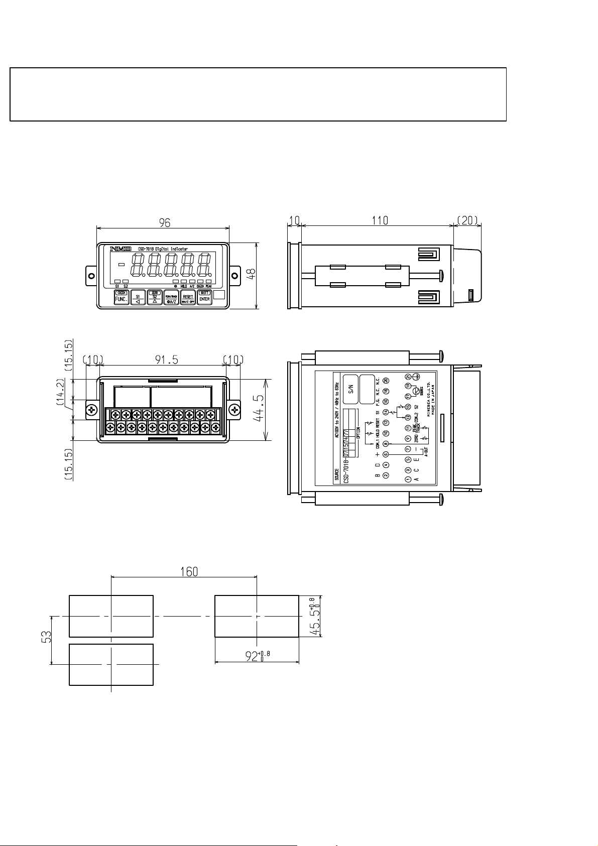
● When installing the instrument, install as referring to the following
figures and secure the space around the instrument.
Each dimensions of the instrument and required dimensions for the environmental
spaces are as follows:
Outline dimensions
Front
Rear
Side
Upper
Panel cut size
Unit:mm
IV
Page 6

2. Power supply
Warning ● Be sure to check that the power supply is off in connecting each cable.
If the work is done while the power is on, there may have the case that
electric shock to the operator or even may have damage to the
instrument.
● Before supplying the power, check that the indication of power supply
voltage/specifications for the instrument and the power going to
supply should be the same.
If they are not equal, contact with Minebea.
If you use the instrument without checking them, it may cause a
damage in the instrument or electric shock to the operator.
● Earth wire should be grounded securely.
When earth wire is not connected, it may cause a malfunction of the
instrument or electric shock to the operator.
3. Application note
Warning ● Before using a new instrument or exchanging the strain gage applied
transducer for a new one, be sure to make calibration. If calibration
will not be made, the correct measuring results may not be obtained
nor which may cause malfunction in the instrument and there may
exist damage in peripheral equipments.
Besides, even though calibration has been made, there may occur the
similar case when the results are not correct, so make calibration,
again.
Warning ● In case of using the instrument, check that the connections are
executed properly. If not connected properly, the correct measuring
result will not be obtained, nor it may cause malfunctions of the
instrument, damage to the peripheral equipments or even more
serious accidents.
V
Page 7

Warning ● When change of setting is made carelessly on the instrument during
measurement, correct measured results may not be obtained and it
may cause malfunction in the instrument and even have the
possibility of damage in peripheral instruments.
Warning ● Do not shock the instrument such as throwing something on it.
If neglected, it may cause destruction of the parts and damage to the
electrical circuits.
Warning ● Do not push the panel sheet on the instrument with the excessive
strong force nor push it with sharp edge object such as a driver.
If neglected, it may cause a damage to the panel switch and even have
the possibility of damage to resist to environments or operational
performances.
Warning ● Don’t remove the cover of the case of the instrument, nor peel off the
panel sheet nor take the instrument into pieces.
If neglected, it may cause a damage to the case and the panel sheet
and even have the possibility of damage to resist to environments or
operational performances.
● At the time of shipment from the factory, the instrument has been
plated with a clear sheet on the panel sheet for protective purpose.
In case of application, use the instrument after removing the
clearsheet first.
VI
Page 8
History of revision
Date Instruction Manual No. Details of revised point
Dec. 2000
Mar. 2001
Mar. 2001
DRW.NO.EN294−1127 First Version ROM Ver. 1.000 or later
ECN No.FN01−02042
− Correction −
P.49 7−1−1. Input signal for external control
“During the holding operation, it is reset condition by short
DRW.NO.EN294−1127−A
DRW.NO.EN294−1127−B
circuit.”→“During the peak hold operation, reset condition
is made by short circuit.”
P.91 9−2−6 Output condition at Positive logic
Output data “Yes”→Condition of transistor “OFF”
Output data “No”→Condition of transistor “ON”
ECN No.FN01−02041 ROM Ver.1.300 or later
− Correction −
5−2−1. 6th step.
Add the clause “
5−2−3. 12th step.
Change the display of “SP−L” and “SP−H”
11−1. Specifications for analog Input filter
“2 Hz”→ “1 Hz(At the “0” setting of the digital filter and
stabilized filter)”
− Change −
7−13. “Key lock”→ “Lock of key function”,
According to this change, following sentence is corrected.
8−2. F−06 “Setting key lock”
→ “Setting the lock of key function”
According to this change, following setence is also
corrected.
It can be increased 〜”
Jun. 2001
Jul. 2001
Sep. 2001
May. 2003
Aug. 2003
DRW.NO.EN294−1127−C
DRW.NO.EN294−1127−D
DRW.NO.EN294−1127−E
DRW.NO.EN294−1127−F
DRW.NO.EN294−1127−G
ECN No.FN01−02085
− Correction ‐
Change the outline dimensions (upper part)
− Additions ‐
9−6−2., 9−7−2, 11−11−6. add the “Power consumption”.
−Correction−
9−2−4.
(1)Equivalent circuit of input section “COM.1”→ “COM.”
(2)Equivalent circuit of output section “▼”→ “▽”
Due to ECN No.FN01−02134
−Changeー
Operating temperature range
“0 ℃ to 50 ℃”→ “−10 ℃ to 50 ℃”
Due to ECN No.FN03−02040
−Correction−
4−3−5.(2) “4mA to 20mA” to “DC4mA to 20mA”
7−2−4., (1), 7−15−4., 6−2., 9−1−1., 9−2−1., 9−2−2.
9−3−1., 11−7., “Display interlock”→“PEAK/Net weight”
Due to ECN No.FN03−02118
− Correction −
11−2. Specifications for digital section
Display range “−99 999”→ “9 999”
VII
Page 9

Date
Apr. 2005
Nov. 2007
Instruction Manual No. Details of revised point
Due to ECN No.FN05−02035
− Addition −
DRW.NO.EN294−1127−H
DRW.NO.EN294−1127−I
At the warning column in the wiring section, the clause of “
As there is a case which standard wiring color is different,
please confirm the inspection data sheet of the load cell
being used.” is added.
Due to ECN No.FN07−02126
− Correction −
9−2−3. “DC−37P−N made by JAE”
to “Equivalent to DC−37P−NR made by JAE”
9−3−4. “DE−9S−N (JAE)”
to “Equivalent to DE−9S−NR made by JAE”
May, 2010
Oct. 2010
DRW.NO.EN294−1127−J
DRW.NO.EN294−1127−K
Due to ECN No.FN10−01019A
− Addition −
11−10.Accessories panel mounting gasket is added.
Due to ECN No.FN10−02140
− Change −
Minebea logo is changed.
VIII
Page 10

INDEX
Forwards Ⅰ.......................................................
Marks and arrangements used in this manual Ⅱ....................................
For safe operation Ⅲ............................................................
1. Installation place Ⅲ.........................................................
2. Power supply Ⅴ............................................................
3. Application note Ⅴ.........................................................
History of revision Ⅶ............................................................
1. General 1.................................................................
1−1. Features 1............................................................
2. Name and function of each point 2..........................................
2−1. Front panel 2.........................................................
2−2. Rear panel 3..........................................................
3. Installation procedures 4...................................................
3−1. Installation place 4....................................................
3−2. Location where installation is not allowed. 4.............................
3−3. Installation 5.........................................................
3−4. Applicable environment 6..............................................
4. Connecting method 7......................................................
4−1. Layout of the terminal boards 7.........................................
4−2. Note on connection 8..................................................
4−3. Connection 9..........................................................
4−3−1. Connection with strain gage applied transducers 9..................
4−3−2. Connection with external control inputs 13..........................
4−3−3. Connection with contact outputs 14.................................
4−3−4. Connection with the power supply and the earth 15...................
4−3−5. Connection with analog outputs 16.................................
5. Calibration procedures 18...................................................
5−1. Preparations 18........................................................
5−2. Calibration procedures 18...............................................
5−2−1. Calibration method to register the output of strain gage applied transducer
at the time of maximum display after setting the load to zero 19........
5−2−2. Calibration procedures to register the output of strain gage applied
transducer at the time of zero and the maximum display 24............
5−2−3. Calibration method to register by reading output value of
strain gage applied transducer in the conditions of
zero/actual load application individually 29..........................
5−2−4. Zero fine adjustment 35............................................
5−2−5. Span fine adjustment 37...........................................
5−2−6. Calibration procedure to apply registration again for zero point only 39
5−3. Selection of calibration methods on each condition 41......................
5−3−1. In case of executing the calibration on the instrument newly. 41.......
5−3−2. When the calibration is executed again. 45...........................
5−4. Setting the prohibition against calibration 45..............................
6. Operation procedure 46.....................................................
6−1.
key 46............................................................
6−1−1. Operations in Measurement mode 46...............................
6−2.
key 46............................................................
Page 11

6−2−1. When operating in the measurement mode 46........................
6−2−2. Operation is made in another mode 47..............................
6−3.
key 47............................................................
6−3−1. When operated in the Measurement mode. 47........................
6−3−2. When operated in another modes 48................................
6−4.
key 48............................................................
6−4−1. When operated in the Measurement mode. 48........................
6−4−2. When operated in another modes 48................................
6−5.
key 49............................................................
6−5−1. When operated in the Measurement mode 49........................
6−5−2. When operated in another modes. 49................................
6−6.
key 49............................................................
7. Function and operation 50...................................................
7−1. External control input signal and contact output signal 50..................
7−1−1. Input signal for external control 50.................................
7−1−2. Contact output signal 51...........................................
7−1−3. Equivalent circuit 51..............................................
7−2. Comparator 52.........................................................
7−2−1. ON/OFF of comparator S1 and S2 52................................
7−2−2. Change of set value 52.............................................
7−2−3. Operation on comparator S1 and S2 54..............................
7−2−4. Comparative target for comparator S1 and S2 55.....................
7−2−5. Hysteresis on comparator 56.......................................
7−3. How to use the filter 58.................................................
7−3−1. Digital filter 58...................................................
7−4. Zero tracking 58........................................................
7−4−1. What is zero tracking? 58..........................................
7−4−2. Setting related with zero tracking. 59...............................
7−4−3. Cancellation for compensation by zero tracking 59...................
7−5. Stabilized filter 60
7−5−1. What is the Stabilized filter? 60.....................................
7−5−2. Setting related with the Stabilized filter. 60..........................
7−6. Change of Peak function and A/Z function 61..............................
7−7. How to use the peak hold. 62.............................................
7−8. Various functions concerning display 63..................................
7−8−1. Selection of target of display 63.....................................
7−8−2. Selection of position of decimal point display 63......................
7−8−3. Load display range 63.............................................
7−9. Selection the target for HOLD 63.........................................
7−10. Change of bridge power supply voltage 64.................................
7−11. Tare weight cancellation (A/Z) 64........................................
7−12. Zero set 64.............................................................
7−13. Lock of key function 65.................................................
7−14. CHECK value 65.......................................................
7−15. How to use the analog output 66.........................................
7−15−1. Scaling of analog output 66........................................
7−15−2. Fine adjustment 1 on analog output 67..............................
7−15−3. Fine adjustment 2 on analog output 70..............................
......................................................
Page 12

7−15−4. Selection of the target of analog output 72...........................
7−16. Memory location for setting data and so on 72.............................
7−17. Prohibition of calibration 72.............................................
7−18. Check mode 73.........................................................
7−18−1. Operating procedure for the check mode 73..........................
7−19. Monitor mode 78.......................................................
8. Function mode 80..........................................................
8−1. Setting method for function mode 80.....................................
8−2. Function of Function data 82............................................
9. Options 88.................................................................
9−1. Current output 88......................................................
9−1−1. Related functions 88..............................................
9−1−2. Specifications for the current output 88.............................
9−2. BCD output 89.........................................................
9−2−1. Related function 89...............................................
9−2−2. Specifications for BCD output 89...................................
9−2−3. Pin configurations for the BCD output connector 89..................
9−2−4. Equivalent circuit for input/output 90...............................
9−2−5. Timing chart 91..................................................
9−2
−6. Output condition 92...............................................
9−2−7. Selection of output logic for P.C.(Print command),
and selection of its width 93........................................
9−3. RS−232C interface 94..................................................
9−3−1. Related function 94...............................................
9−3−2. Specifications for interface 94......................................
9−3−3. Procedures of data transfer 95......................................
9−3−4. Pin configurations for connector pin 96.............................
9−3−5. Data format 97...................................................
9−3−6. Communication error process 100...................................
9−4. RS−422 interface 101....................................................
9−4−1. Related functions 101..............................................
9−4−2. Specifications on interface 102......................................
9−4−3. Procedure of data transmission 102..................................
9−4−4. Pin layout and wiring of Connector 103..............................
9−4−5. Data format 104...................................................
9−4−6. Process of communication error 106.................................
9−5. Serial interface 107......................................................
9−
5−1. Related function 107...............................................
9−5−2. Specifications for Interface 107......................................
9−5−3. Connecting method and internal equivalent circuit 108................
9−5−4. Data format 109...................................................
9−5−5. Explanation of format data 110......................................
9−5−6. Explanation of output type 110......................................
9−6. Power supply voltage DC12 V(CSD701B−P66) 111........................
9−6−1. Layout of the terminal boards 111...................................
9−6−2. Connection with the power supply and the earth 112...................
9−7. Power supply voltage DC24 V(CSD701B−P67) 113........................
9−7−1. Layout of the terminal boards 113...................................
9−7−2. Connection with the power supply and the earth 114...................
10. Trouble shooting 115........................................................
Page 13

10−1. Execute trouble shooting 116.............................................
10−2. Optional check 125......................................................
10−3. Error display 131........................................................
11. Specifications 132...........................................................
11−1. Specifications for analog section 132.......................................
11−2. Specifications for digital section 132.......................................
11−3. Front panel sheet key function 133........................................
11−4. External control function 133.............................................
11−5. Comparator function 134.................................................
11−6. Contact output signal 134................................................
11−7. Various kinds of functions 134............................................
11−8. General specifications 134................................................
11−9. Standard specifications at the shipment 135................................
11−10. Accessories 135..........................................................
11−11. Options 135.............................................................
11−11−1. Current output 135................................................
11−11−2. BCD output 135...................................................
11−11−3. RS−232C interface 135.............................................
11−11−4. RS−422 interface 137..............................................
11−11−5. Serial interface 137................................................
11−11−
11−12. Outline dimensions 138..................................................
6. Power supply voltage 137...........................................
12. Warranty 139................................................................
12−1. Warranty 139...........................................................
12−2. Repair 139..............................................................
13. Appendix 140................................................................
13−1. Replacement of fuse 140..................................................
13−2. Character’s pattern for display 142........................................
13−3. Setting table for functions 143............................................
Page 14

1. General
The instrument is a digital indicator for the application of strain gage applied transducer.
1−1. Features
Main features for CSD−701B are as follows :
(1) Compact size and light weight
48 mm×96 mm×120 mm Approx.0.3 kg (Without any options)
(2) The A/Z function and the peak holding function can be used by the selection.
1
Page 15
2. Name and function of each point
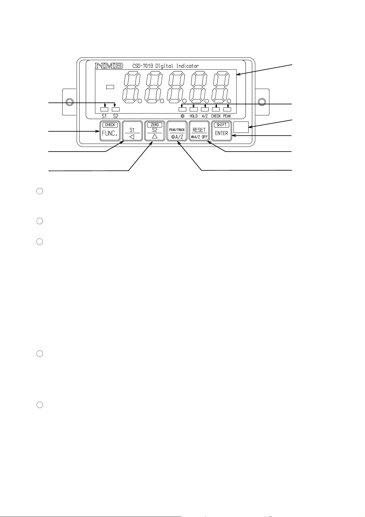
2−1. Front panel
①
②
④
⑤
⑥
1
Load display section
The load data is shown in the Measurement mode, and status or set value is shown in various
kinds of Calibration mode and Setting mode.
2
Judgement display
Compared results by comparator function can be displayed.
3
Status display
◎ Lights up when selecting A/Z or A/Z OFF function in the Function mode.
In the same way, light off when selecting Peak hold function in the Function
mode.
HOLD Lights up when between the HOLD and COM.1 at the external control input is
shorted.
A/Z Lights up at the time of executing Tare weight cancellation(A/Z ON).
Lights off with the tare weight cancellation clear.
(Effective when selecting the A/Z or A/Z OFF function in the function mode.)
CHECK Lights up when the CHECK is ON.
PEAK Lights up when selecting the Peak mode.
③
⑩
⑨
⑧
⑦
4
key
Used when shifting to the Function mode.
Also, by pressing this key and the
turned on and off
5
key
Used when calling the S1 set value changeover mode, or carrying digit at the time of various
kinds of settings.
key together, it is used when the CHECK value is
2
Page 16
6
key
Used when calling the S2 set value changeover mode, or for the increment of values at the time
of various kinds of settings.
Also, by pressing this key and the
zero adjustment).
7
key
Used for making the changeover mode of Peak/Track, or executing the Tare weight
cancellation (A/Z ON).
(Changeover of Peak hold function and A/Z function depends on the setting of Function mode.)
8
key
Used for the reset of Peak value, or for Tare weight cancellation clear(A/Z OFF).
(Changeover of Peak hold function and A/Z function depends on the setting of Function mode.)
9
key
Used for registering set values at the time of various kinds of settings.
Also, by pressing this key and the
turned on and off.
Also, by pressing this key and
adjustment).
key together, it will execute the set of zero(One−touch
key together, it is used when the CHECK value is
key together, it will execute the set of zero(One−touch zero
10
Position of pasting the Unit seal
As necessity requires, paste the Unit seal attached.
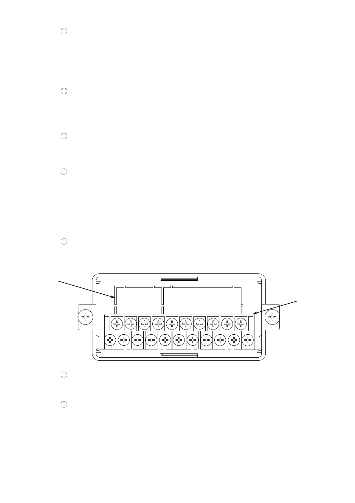
2−2. Rear panel
②
1
Terminal board
Connects with external control input, contact output, various kinds of strain gage applied
transducer such as load cell, analog output, AC power supply, and a grounding wire.
2
Installing section for options
Whichever one can be installed from the optional BCD−OUT, RS−232C, RS−422 or serial
interface.
①
3
Page 17

3. Installation procedures
3−1. Installation place
● Use the instrument where the temperature/humidity specifies within
the range as follows:
Environmental temperature :−10 ℃ to 50 ℃
Environmental humidity :85 %RH or less(Non condensing.)
3−2. Location where installation is not allowed.
Warning ● Don’t locate the instrument on the places such as follows:
It may cause an unexpected faulty in the instrument.
D Do n ot expose the instrument in direct sunlight and/or high temperature area.
D Do n ot use the instrument in a high humid area.
D Do n ot install the instrument where there is high mechanical vibrations and shock.
D Do n ot use the instrument where there are excess of dusts and fine particles.
D Do n ot install the instrument where there include any corrosive gas or any salty
atmosphere.
D Do not install the instrument where there is rapid change of temperature and humidity.
D Do n ot install the instrument near the devices that are magnetized or generate an
electromagnetic field.
D Do n ot install the instrument where there may suffer radioactivity or radioactive rays.
D Avoid the location where chemical reaction may take place such as in a laboratory, or like
that.
4
Page 18
3−3. Installation
● When installing the instrument, install as the following figures and
secure the space around the instrument.
Each dimensions of the instrument and required dimensions for the environmental spaces are as
follows:
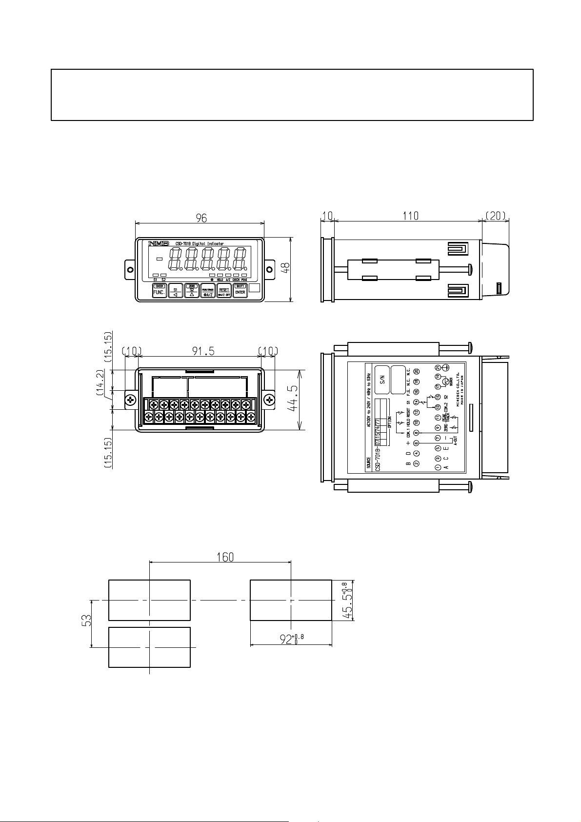
Outline dimensions
Front
Side
Rear
Panel cut size
Upper
Unit:mm
5
Page 19
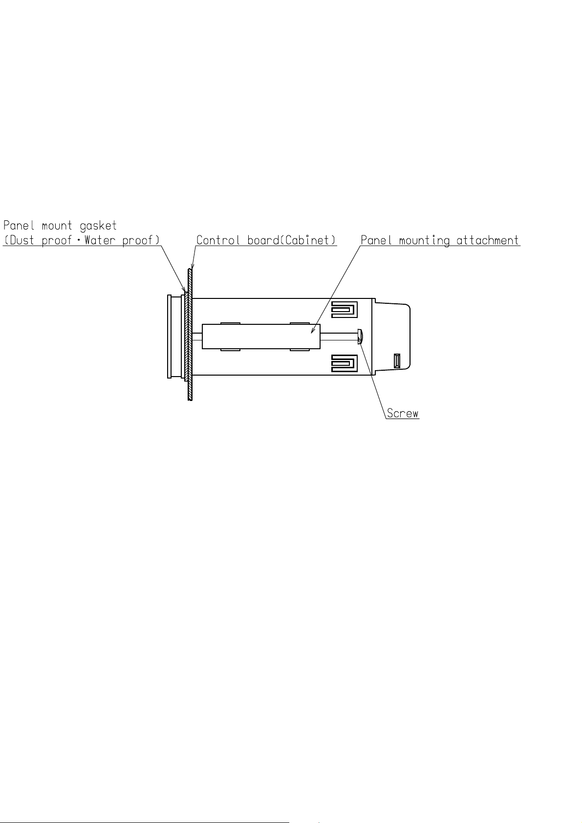
3−4. Applicable environment
Warning: The instrument may subject to use in a highly humid area or in full of powder dust.
In such a case, use the instrument by inserting the panel mount gasket attached between the con-
trol panel (cabinet) and the main body
.
By inserting the panel mount gasket, the front panel section becomes IP65 (Inter-
national Protection Code) or equivalent in dust−proof and water−proof construc-
tion.
* Care should be taken when handling the panel mount gasket, since there are up
and down directions.
6
Page 20
4. Connecting method
External
control
applied
p
Anal
input
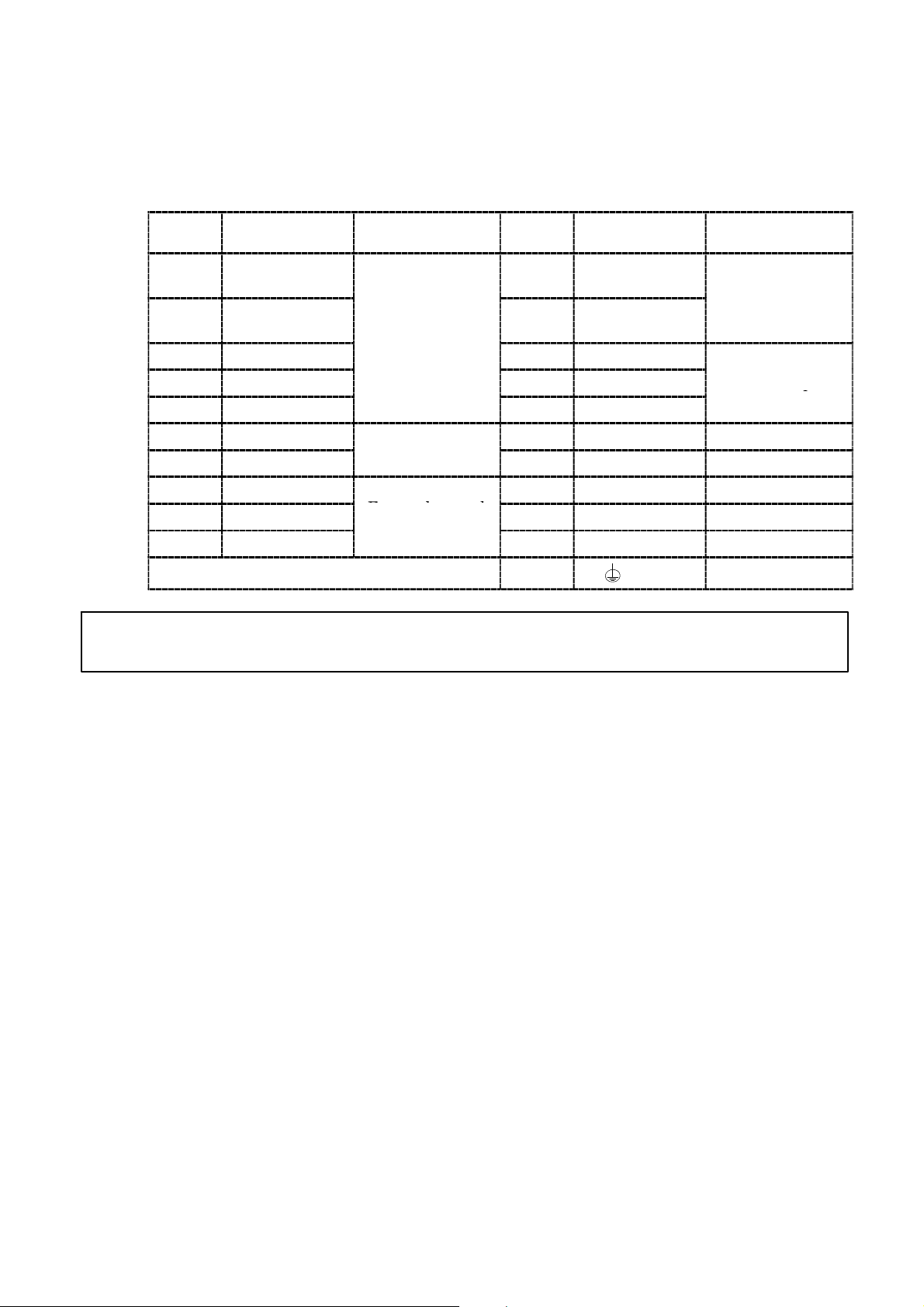
4−1. Layout of the terminal boards
There is one terminal board containing 21 point of terminals in the panel.
Layout of terminal boards are shown in the following figure.:
Termin
al No.
1 A 11
2 B Strain gage
3 C
4 D 14 S1
5 E 15 S2
6 A−OUT +
7 A−OUT −
8 COM.1
9 ZERO
10 HOLD
Descriptions Applications
transducer
og output
External control
Termin
al No.
12
13 COM.2
16 F. G Frame ground
17 SOURCE AC power supply
18 N.C.
19 SOURCE AC power supply
20 N.C.
21 Ground
Descriptions Applications
PEAK/TRACK
or A/Z
RESET or A/Z
OFF
External control
input
Contact output
● The COM.1(Terminal No.8) and COM.2(Terminal No.13) are isolated.
7
Page 21
4−2. Note on connection
Warning ● In case of connection with the instrument, keep strictly to the
following items. If neglected, it may cause an unexpected failure
or a damage to the instrument.
D Be sure to set the power supply to OFF, when the connection will be made.
D Since the terminal boards at rear side of the instrument is made of resin, take care not to
drop it down or not to apply strong impact.
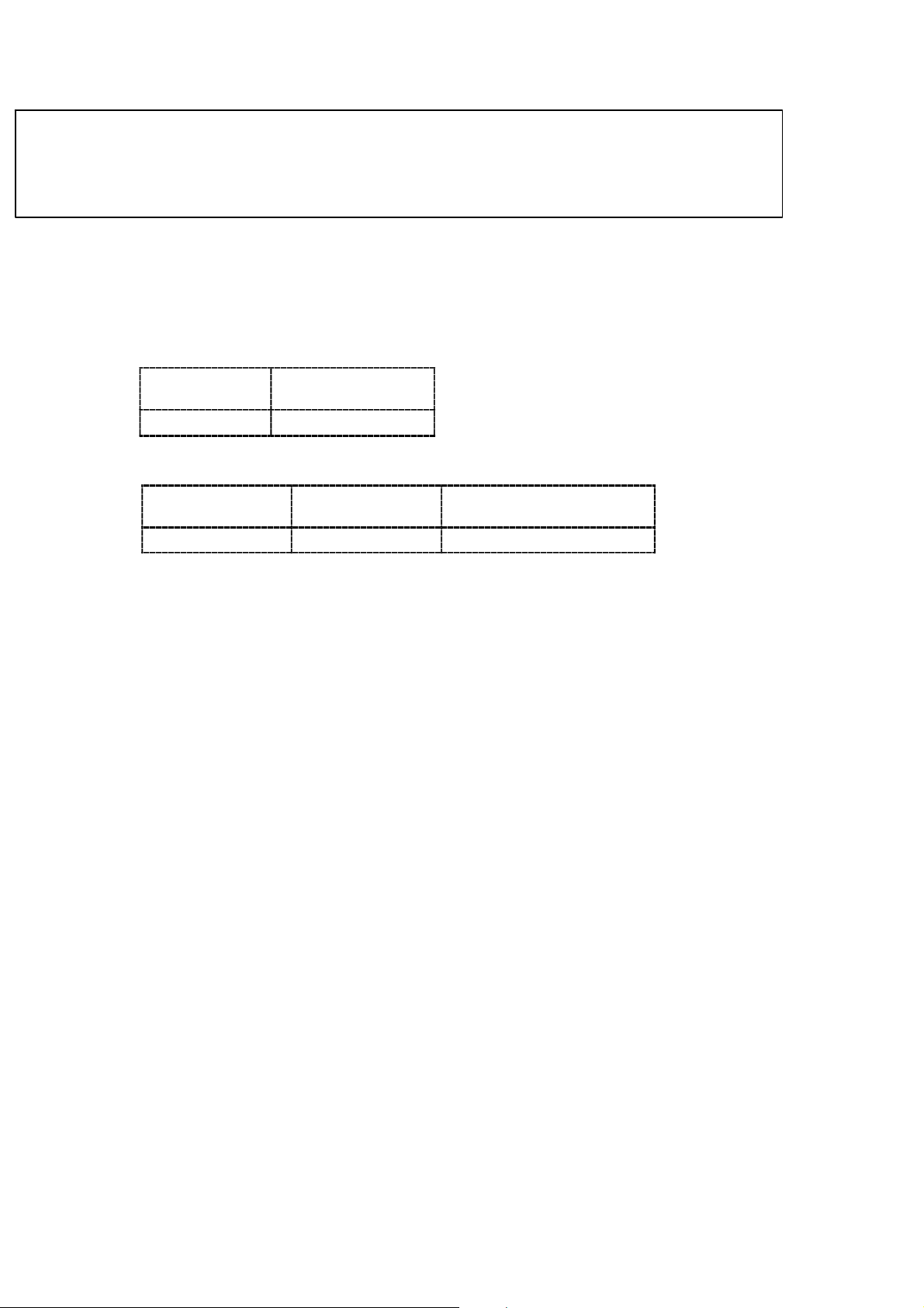
D Recommended torque to tighten the terminal screws for terminal board should be as
follows:
Torque to tighten
the terminal screws
Terminal board 0.6 N・m
D The suitable crimp type terminal lugs for the terminal board are as follows:
Width of crimp
type terminal lugs
Terminal board 6.2 mm or less 1.25−3 or Y type 1.25−3.5
D Connecting cable with the instrument should be away from the noise source such as power
supply line and/or I/O line for control and so on as far as possible.
D Conduit wiring should be the type of exclusive one, and avoid using with another line
together.
D All of the connections should be executed securely by referring to the Instruction manual
for the instrument.
Suitable crimp type
terminal lugs
8
Page 22
4−3. Connection
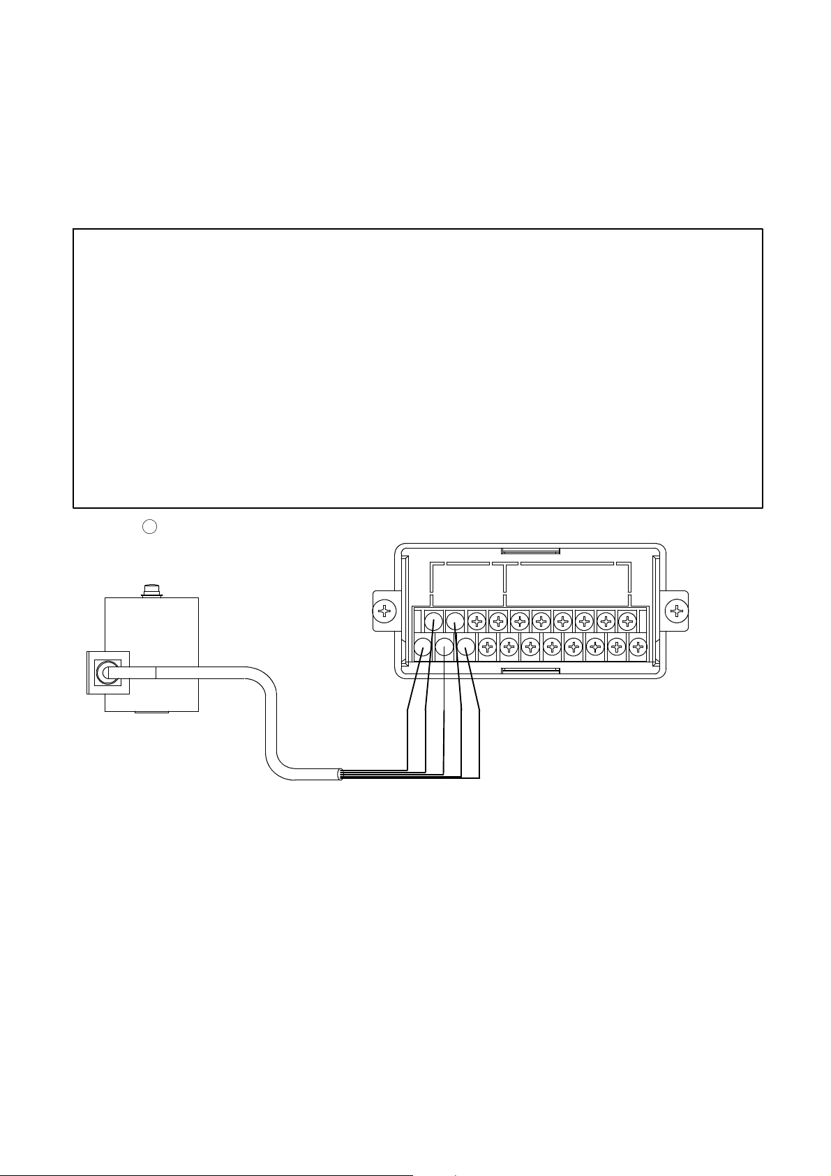
4−3−1. Connection with strain gage applied transducers
The instrument can connect with strain gage applied transducers, such as load cell, pressure
transducer and so on. Here, we will describe the example of connections with load cell, so the
connection with other type of strain gage applied transducers shall be proceeded in the same
way.
※1 When tension is applied with the application of tension type or
universal(compression/tension) type of load cell, and display of “+”
direction is required, connect “Green” with Terminal No.2 and
“Blue” with Terminal No.4 individually. As there is a case which
standard wiring color is different, please confirm the inspection data
sheet of the load cell being used.
※2 When the length of CAB−502 is more than 30 m totally, there may
have the case that the accuracy is out of warranty because the
resistance of cable makes the input voltage of the instrument
decreased.
1
Connection with 1 piece of load cell and CSD−701B
3m
※1※
1
RED
WHT
BLU
GRN
Shield
9
Page 23
※1 When tension is applied with the application of tension type or
universal(compression/tension) type of load cell, and display of “+”
direction is required, connect “Green” with Terminal No.2 and
“Blue” with Terminal No.4 individually. As there is a case which
standard wiring color is different, please confirm the inspection data
sheet of the load cell being used.
※2 When the length of CAB−502 is more than 30 m totally, there may
have the case that the accuracy is out of warranty because the
resistance of cable makes the input voltage of the instrument
decreased.
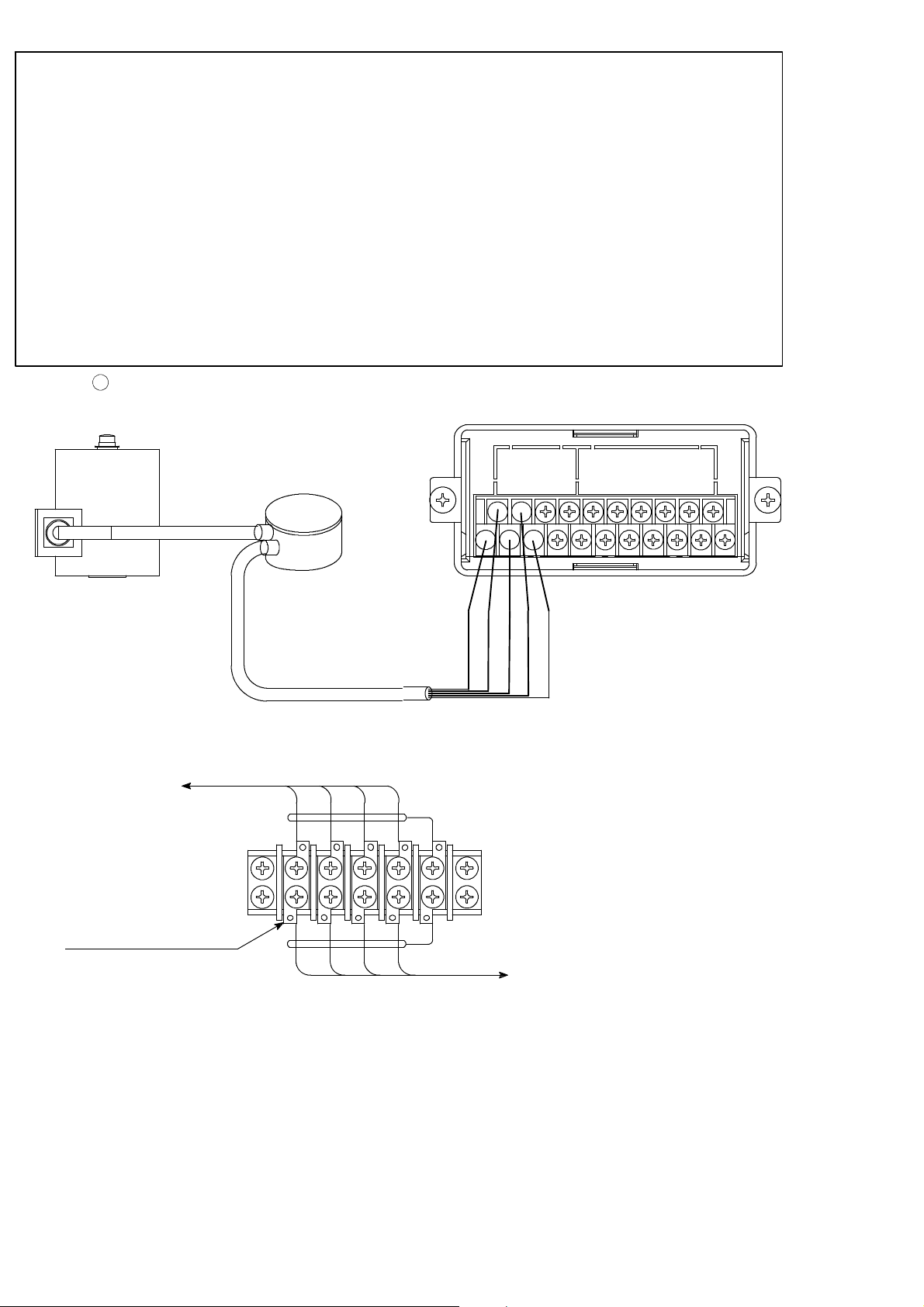
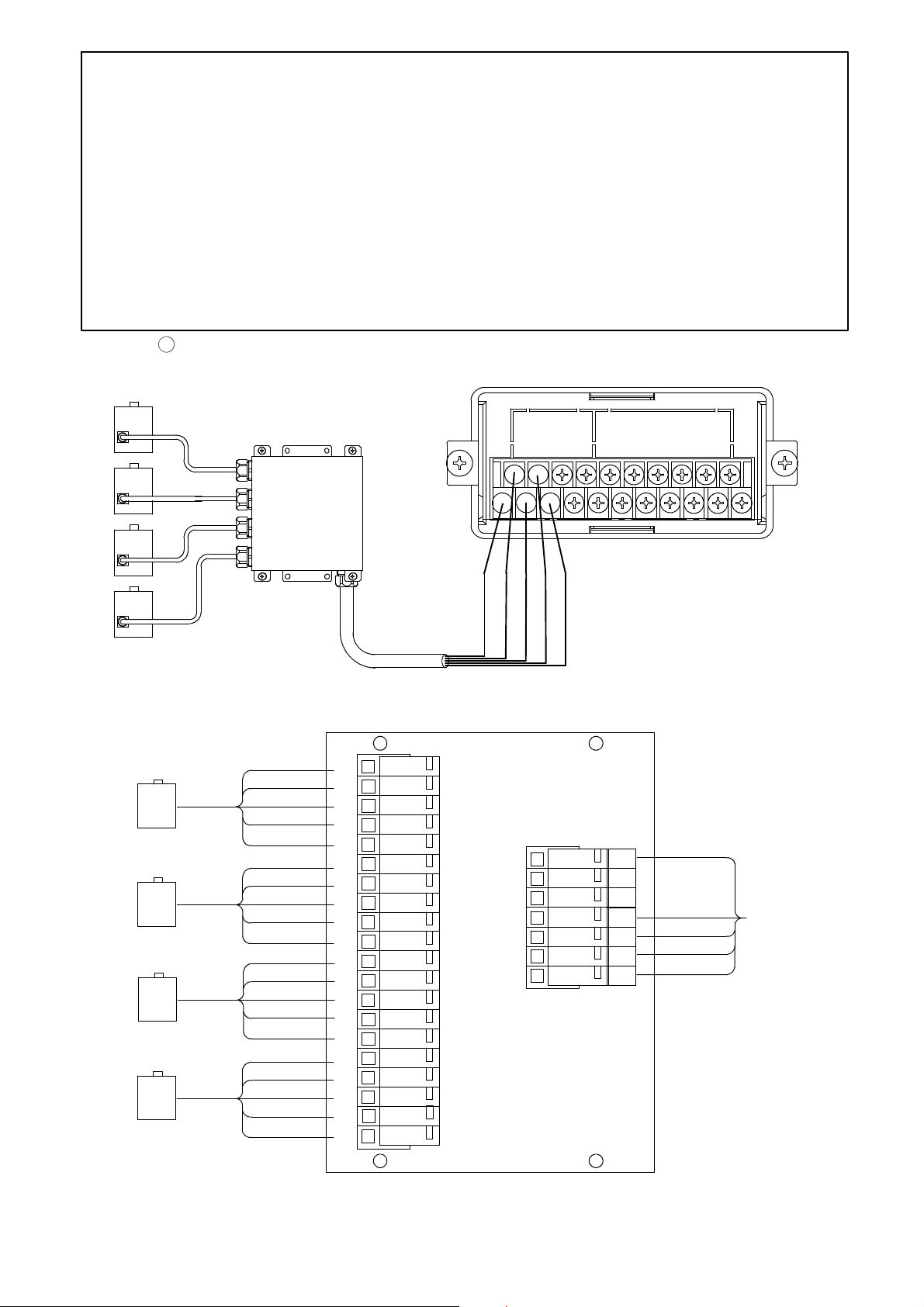
2
Connection with 1 piece of load cell and Junction box for extension use(B−304) and
CSD−701B.
Junction box
3m
※2 (Total length of CAB−502 is within 30 m)
Internal wiring diagram of B−304
to load cell
Terminal pitch 9.5 mm
B−304
CAB−502
RED WHTBLU
RED WHTBLU
※1※
RED
BLU
GRN YEL(Shield)
Suitable crimp type terminal lugs
:1.25−4or2−4
YEL(Shield)
GRN
1
WHT
GRN
Shield
to CSD−701B
10
Page 24
※1 When tension is applied with the application of tension type or
universal(compression/tension) type of load cell, and display of “+”
direction is required, connect “Green” with Terminal No.2 and
“Blue” with Terminal No.4 individually. As there is a case which
standard wiring color is different, please confirm the inspection data
sheet of the load cell being used.
※2 When the length of CAB−502 is more than 30 m totally, there may
have the case that the accuracy is out of warranty because the
resistance of cable makes the input voltage of the instrument
decreased.
3
Connection with 2 to 4 pieces of load cells, Summing type junction box(B−307) and
CSD−701B.
Junction box
B−307
CAB−502
※2 (Total length of CAB−502 is within 30 m)
Internal wiring diagram of B−307
WHT
RED
GRN
BLU
YEL(Shield)
WHT
RED
GRN
BLU
YEL(Shield)
WHT
RED
GRN
BLU
YEL(Shield)
WHT
RED
GRN
BLU
YEL(Shield)
1W
1R
1G
1B
1Y
2W
2R
2G
2B
2Y
3W
3R
3G
3B
3Y
4W
4R
4G
4B
4Y
※1※
RED
BLU
1
WHT
GRN
Shield
RED
RD
OR
BK
WHT
WH
GN
BL
YE
GRN
BLU
YEL(Shield)
to CSD−701B
11
Page 25
※1 When tension is applied with the application of tension type or
universal(compression/tension) type of load cell, and display of “+”
direction is required, connect “Green” with Terminal No.2 and
“Blue” with Terminal No.4 individually. As there is a case which
standard wiring color is different, please confirm the inspection data
sheet of the load cell being used.
※2 When the length of CAB−502 is more than 30 m totally, there may
have the case that the accuracy is out of warranty because the
resistance of cable makes the input voltage of the instrument
decreased.
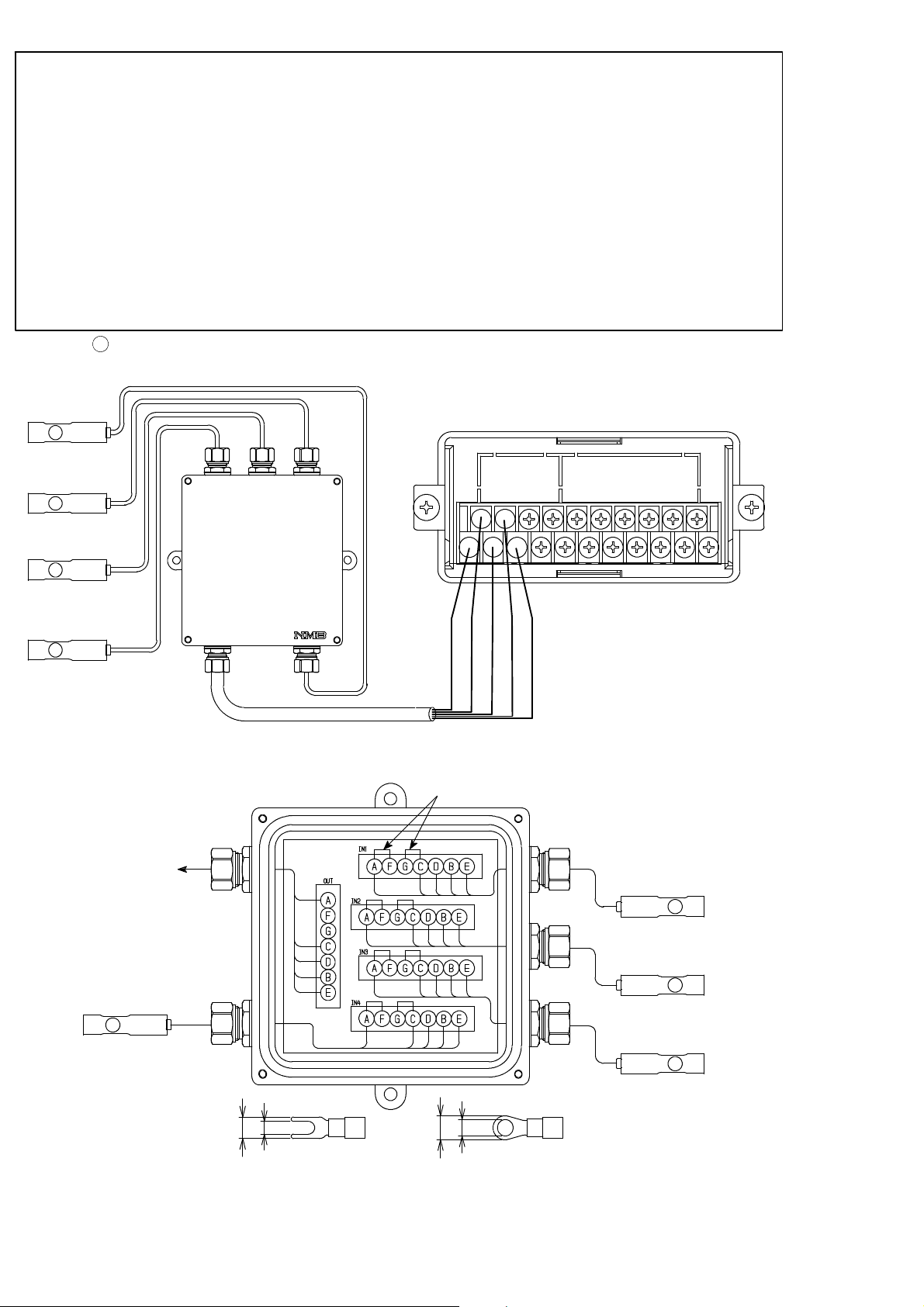
4
Connection with 2 to 4 pieces of load cells, Summing type junction box(SB−310) and
CSD−701B.
SB−310
CAB−502
※2 (Total length of CAB−502 is within 30 m)
Internal wiring diagram of SB−310
Output port
to CSD−701B
RD
WH
GR
Input port
No.4
BL
YE
※1※
RED
BLU
Short bar
YERD WH BLGR
YERD WH BLGR
YERD WH BLGR
YERD WH BLGR
1
WHT
GRN
Shield
Input port No.1
Input port No.2
Input port No.3
Suitable crimp type
terminal lugs:
A
B
or
φB
φA
A:3.2 mm or less
B:7 mm or less
・Y type ・Round type
12
Page 26
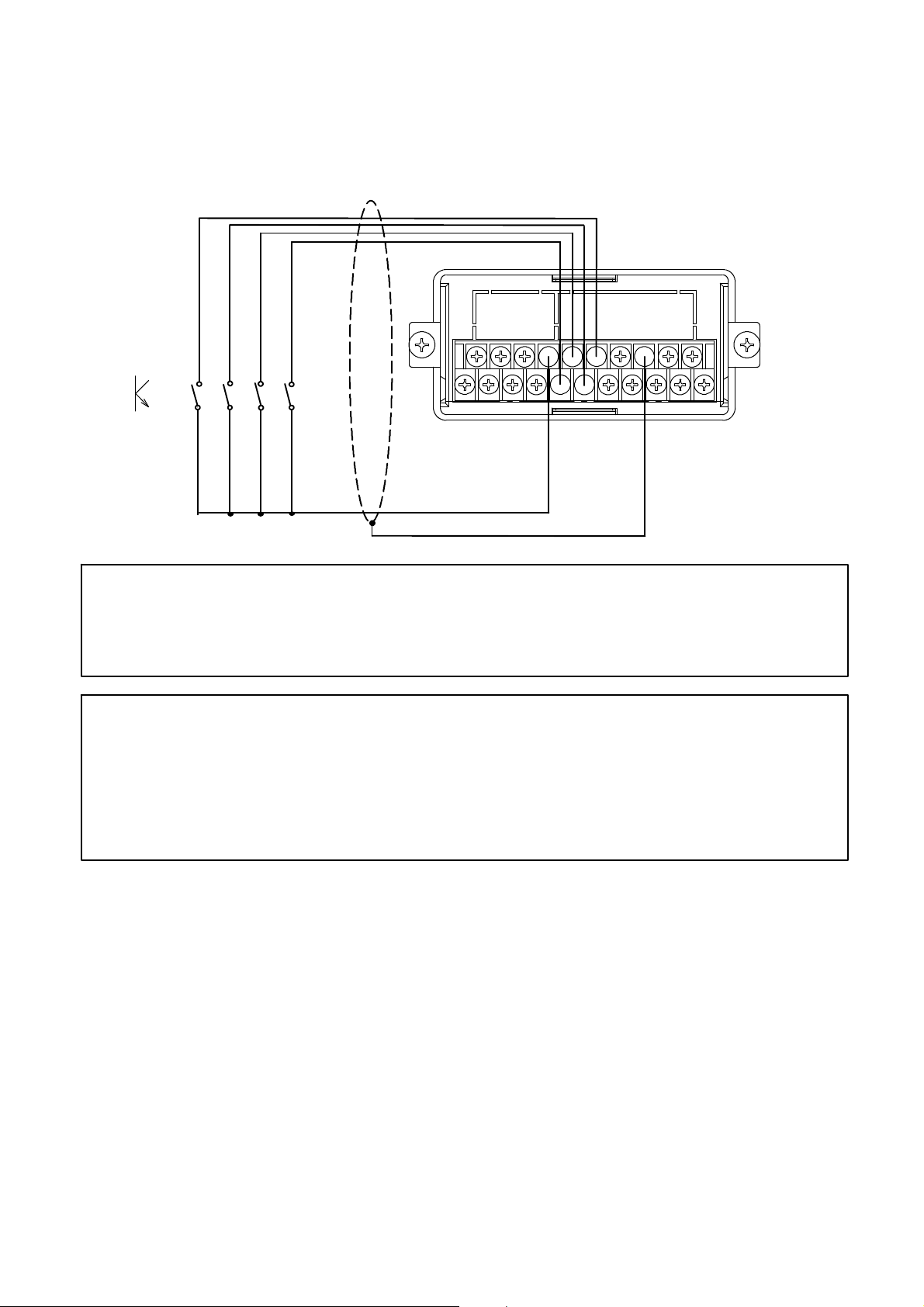
4−3−2. Connection with external control inputs
Connections with external control input “ZERO”,“HOLD”, “PEAK/TRACK” and “RESET”
should be made according to the below figures by using a contact point or an open collector
between the each terminal and terminal No. 8 at “COM.1”
Refer to the paragraph 7−1 for the function of each input.
or
Shield
Warning ● Connections with external control outputs should be made securely
according to the figures. If neglected, it may cause an unexpected
failure and/or malfunction to the instrument.
● For the connections with external control inputs, be sure to apply
shielded cable, and the shielded cable should be connected with GND
terminal of the instrument.(Terminals No.16)
If not connected, it may cause malfunction due to the effects from
external noises and so on.
13
Page 27
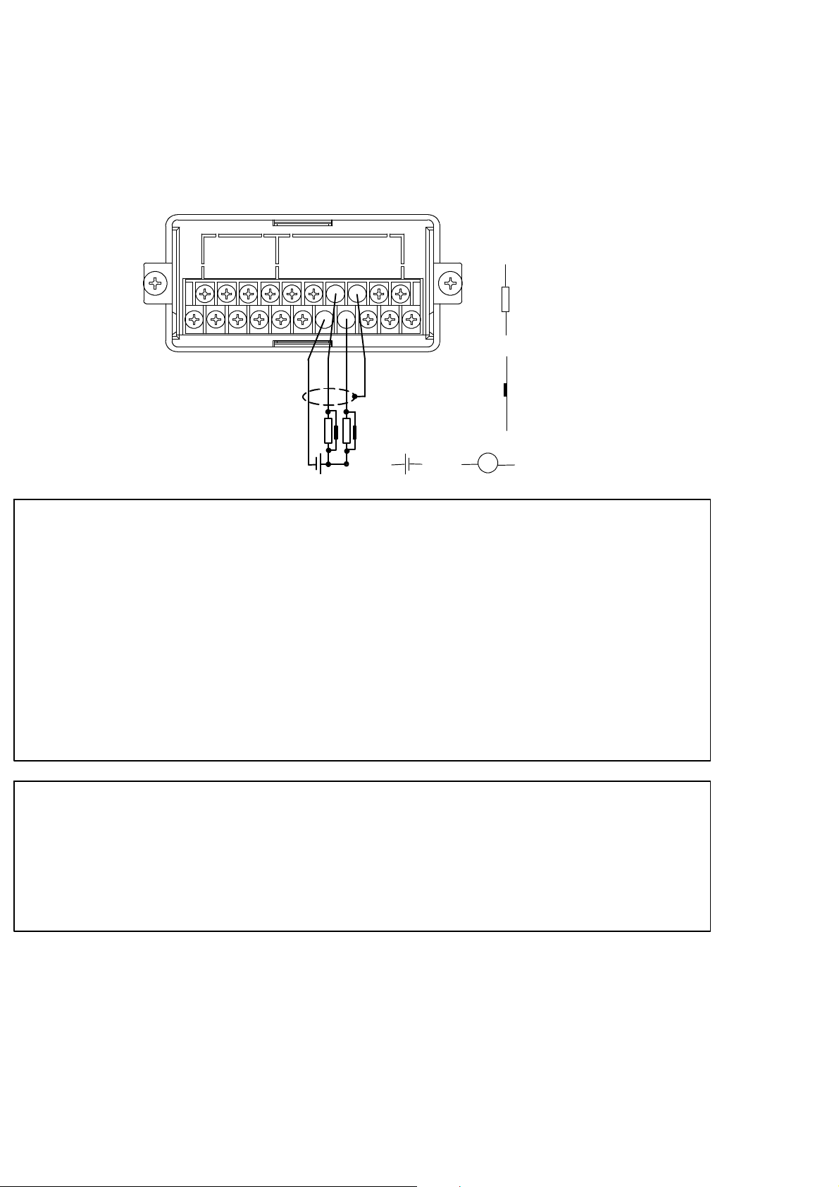
4−3−3. Connection with contact outputs
Connections with contact outputs “S1” and “S2” and external load should be made by using
each terminal and terminal No. 13 at “COM.2”.
At the same time, take care that the load should not exceed the rated load of contact output.
Rated load of contact output AC125 V 0.1 A (Resistance load)
DC30 V 0.5 A (Resistance load)
load
Surge preventive element
〜
or
Shield
or
Warning ● Connections with contact outputs should be made securely according
to the figures and also within the rated capacity of the instrument. If
neglected, it may cause an unexpected failure and/or malfunction to
the instrument.
● For the protection from the contact of the instrument, connect the
surge preventive element that satisfies the characteristics of external
load to connect. If neglected, it may cause unexpected failure and/or
malfunction due to the effects from damage/melt down of the contact
and so on.
● For the connections with contact outputs, be sure to apply shielded
cable, and the shielded cable should be connected with GND terminal
of the instrument.(Terminal No.16)
If not connected, it may cause malfunction due to the effects from
external noises and so on.
14
Page 28
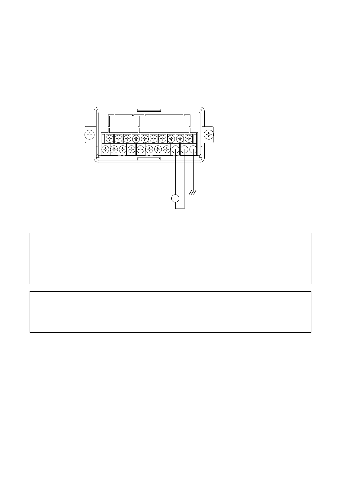
4−3−4. Connection with the power supply and the earth
Connections with the power supply and the earth should be made as the following figure.
Grounding should be the D class with single earth.
Power supply voltage AC100 V to AC240 V
(Allowable variable range:AC85 V to AC264 V)
Frequency for power supply 50/60 Hz
Power consumption Approx.11 VA at maximum. (at AC100 V)
D class with single earth
〜
AC100 V to AC240 V
(Allowable variable range
:AC85 V to AC264 V)
Warning ● Connections with the power supply and the earth should be made
securely according to the figures and also within the rated capacity of
the instrument. If neglected, it may cause an unexpected cause of
failure.
● Grounding should be the D class with single earth.
If neglected, it may cause an unexpected malfunction due to the
effects of noise from other equipments.
15
Page 29
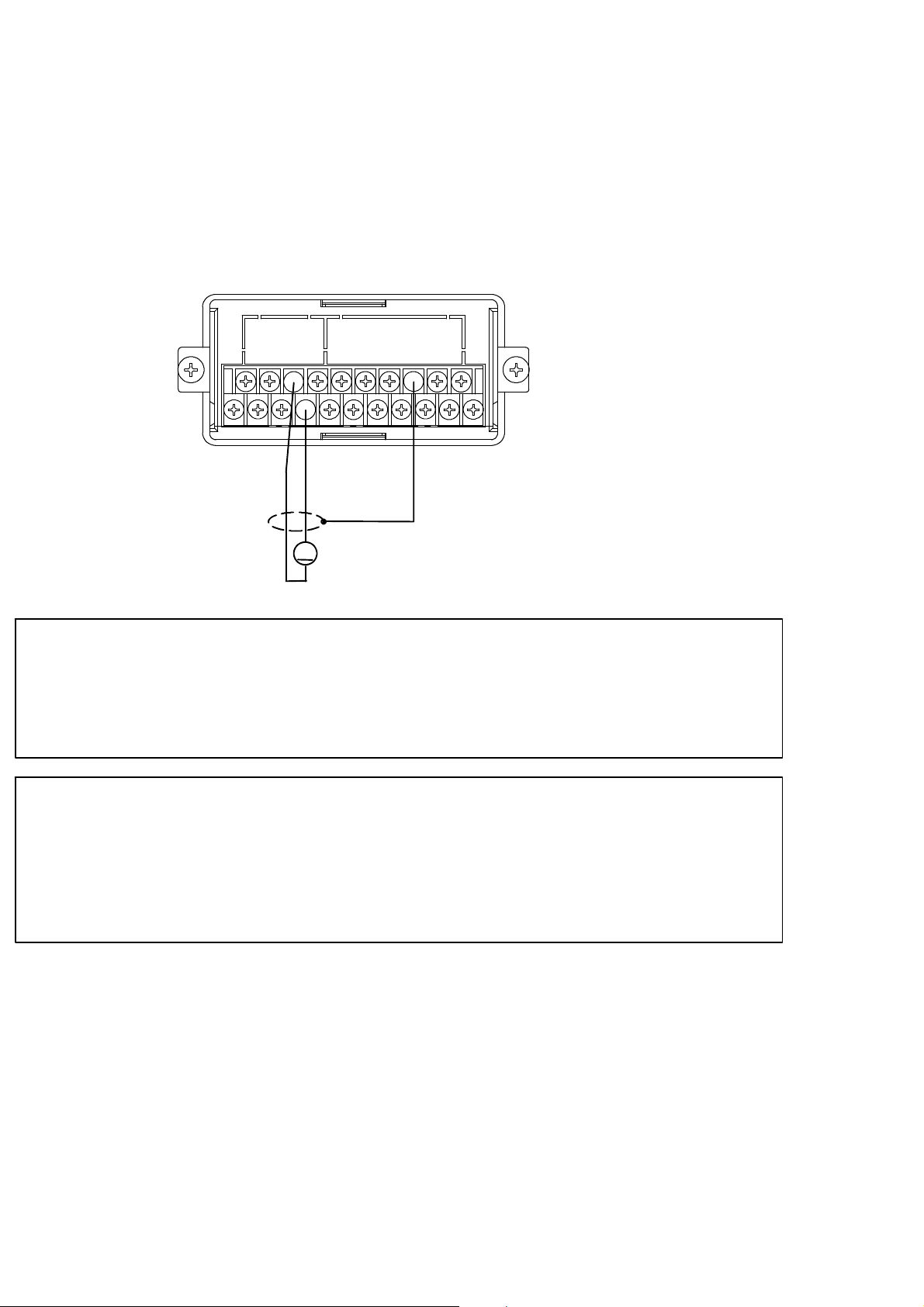
4−3−5. Connection with analog outputs
(1) In case of standard instrument (voltage output)
The instrument prepares output voltage for analog outputs as a standard.
Connections with voltage output should be made as the following figure.
Voltage output DC0 V to 5 V
Over−range At “−OL” display Approx.−1.25 V
At “OL” display Approx.6.25 V
Load resistance 5 kΩ or more
Shield
−
V
+
Warning ● Connections with voltage outputs should be made securely according
to the figures and also within specified load resistance.
If neglected, it may cause an unexpected failure and/or malfunction to
the instrument.
● For the connections with voltage outputs, be sure to apply shielded
cable, and the shielded cable should be connected with the F.G.
terminal of the instrument(Terminal No.16).
If not connected, it may cause malfunction due to the effects from
external noises and so on.
16
Page 30
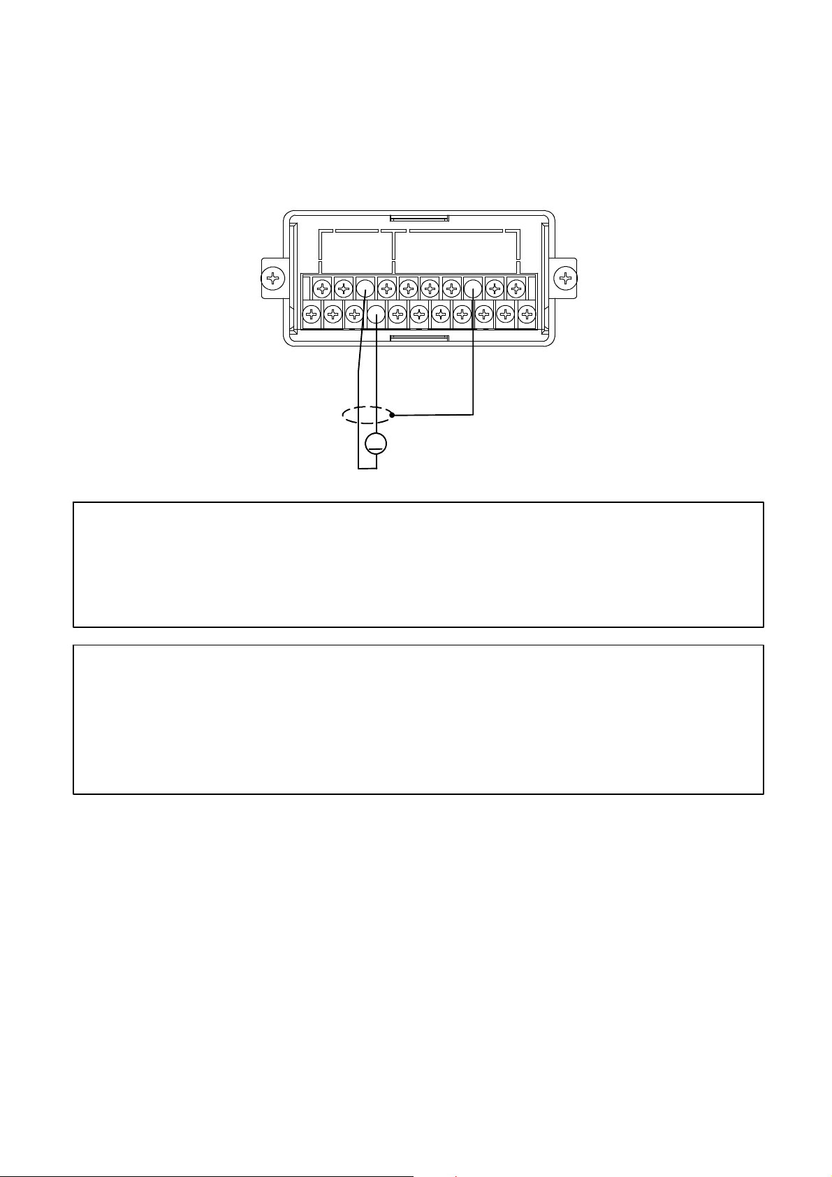
(2) In case of option (current output)
Connections with current output should be made as the following figure.
Current output DC4 mA to 20 mA
Over−range At “−OL” display Approx.0 mA
At “OL” display Approx.24 mA
Load resistance 260 Ω or less
Shield
−
A
+
Warning ● Connections with current outputs should be made securely according
to the figures and also within the specified load resistance.
If neglected, it may cause an unexpected failure and/or malfunction to
the instrument.
● For the connections with current outputs, be sure to apply shielded
cable, and the shielded cable should be connected with the F.G.
terminal of the instrument.(Terminal No.16)
If not connected, it may cause malfunction due to the effects from
external noises and so on.
17
Page 31

5. Calibration procedures
Warning ● Before using the new instrument or after exchanging the strain gage
applied transducer with a new one, be sure to make calibration.
If calibration is not made, correct measured results may not be
obtained, or it may cause malfunction to the instrument and it may
damage the peripheral equipment.
Moreover, even if calibration has made, there may occur the similar
case as above when the result is not correct. So make precise
calibration again.
● The calibration for the instrument and “Display value at the time of
minimum analog output”(F−21) and “Display value at the time of
maximum analog output” (F−22) are not interlocked. In due course,
make check on the setting for F−21 and F−22 securely.
If neglected, correct outputs may not be obtained, or it may cause
malfunction to the instrument and it may damage the peripheral
equipment.
5−1. Preparations
According to the Chapter 4. Connecting method, connect the instrument and the strain gage
applied transducer properly, then supply the power.
5−2. Calibration procedures
Load calibration procedures for the instrument are as follows:
1
Calibration method to register the output (conversion with mV/V) of strain gage applied
transducer at the time of maximum display (weighing capacity) after setting the load to zero
(Initial load condition with tare weight).
2
Calibration method (Automatic calibration for Zero and Span) to register the output of strain
gage applied transducer (conversion with mV/V) at the time of zero load(Initial load
application with tare) at the optional load condition, and also to register the output
(conversion with mV/V) of strain gage applied transducer at the time of maximum display
(weighing capacity).
3
Calibration method (Actual load calibration) to register by the reading output of strain gage
applied transducer, when setting in the condition of zero load applied (Initial load application
with tare) and in the condition of actual load applied individually.
4
Fine adjustment on Zero
5
Fine adjustment on Span
6
Calibration procedures to apply registration again for zero point only(Tare weight
cancellation).
18
Page 32

● The accuracy of calibration obtained from ① and ② is 1/1 000 or so.
If more than the accuracy 1/1 000 is required, make calibration of ③
type.
In the following paragraphs, we will describe each calibration procedure by showing the
examples with load cell applied.
5−2−1. Calibration method to register the output of strain gage applied transducer at the time
of maximum display after setting the load to zero.
Warning ● Before using a new instrument or exchanging the strain gage applied
transducer for a new one, be sure to make calibration.
If calibration shall not be made, correct measured results may not be
obtained nor it may cause malfunction in the instrument and there
may exist damage to the peripheral equipment.
Besides, even though the calibration has been made, there may occur
the similar case when the result is not correct, so make calibration
again.
● During the calibration is executing, be sure to set Tare weight
cancellation clear, and to make cancellation (Execution of F−98) for
compensated data on zero set and set the OFF position of Zero
tracking(Setting “00000” on F−07 and F−08), and also set the OFF
position o Peak.
● During calibration procedures, press the key in case of
interrupting the calibration is required. The calibration data will be
kept as they are before entering the calibration and then returns to
the Measurement mode.
● Every time the
the display will change as the following arrow marks. However, every
time the
direction of the following arrow marks.
key is pressed, the display will change as the reverse
key is pressed with the load display of ”FUNC”,
“FUNC”→“CCAL”→“ACAL”→“LCAL”→“ZERO”→“SPAN”→
“TARE”→“TARE”→“CHEK”→“MONT”→“VCAL”→“VADJ”→
“FUNC”→“CCAL”→・・・・・ (Hereinafter, it will repeat.)
19
Page 33

Procedures
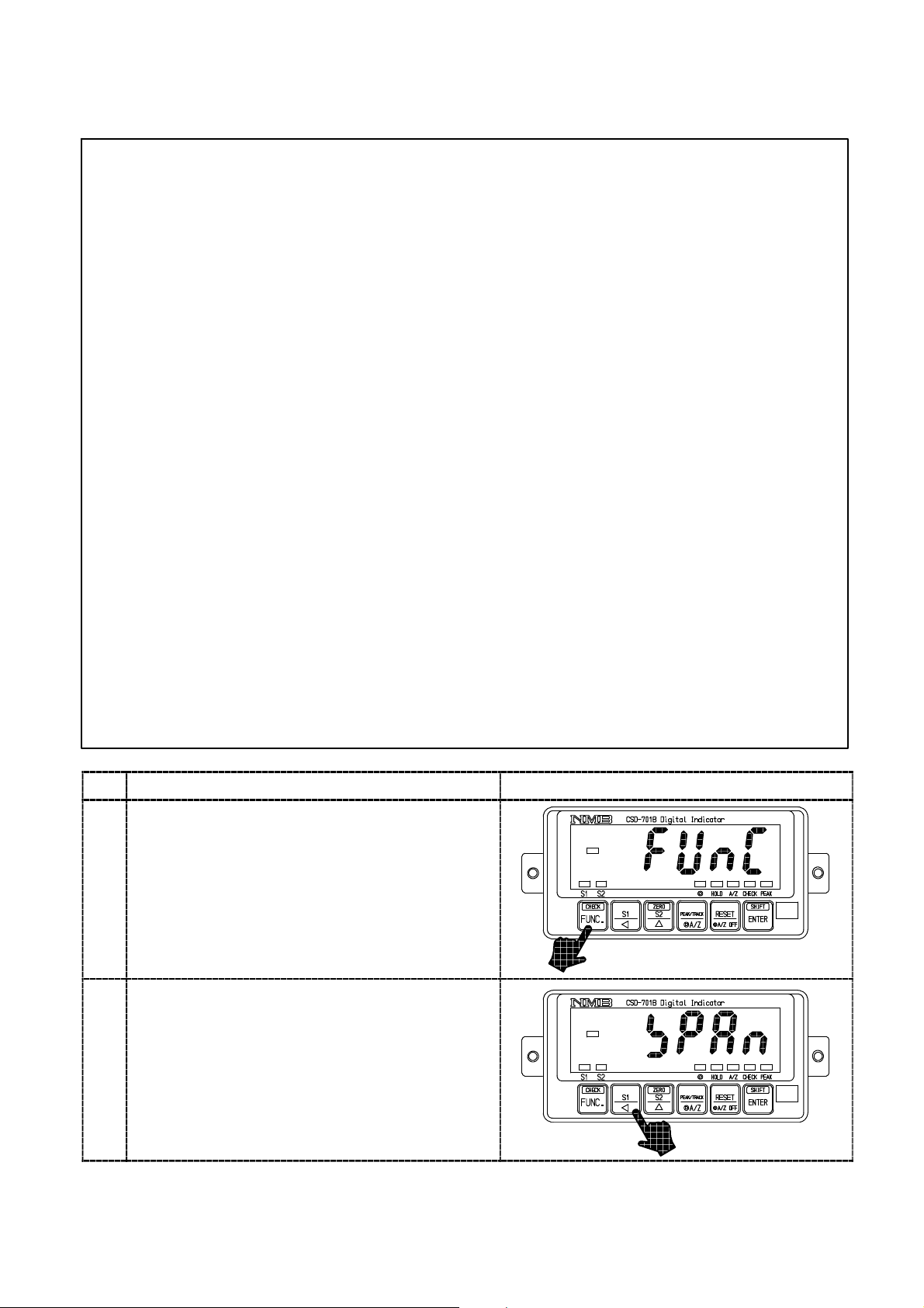
Press the key for approx. one second.
The load display will show “FUNC”.
1
Press the key once.
The load display will show “CCAL”.
2
Press the key.
“CCAL” mode can be entered, then the load
display will show “SCAL”.
3
Press the key.
The load display shows “D−01” and it will flash
on and off.
When the calibration has completed already, the
set value of minimum scale registered at that
4
time will be displayed.
Set the minimum scale with the right keys.
Setting value for the minimum scale will be 4
(four) as follows:
1, 2, 5, 10
Press the key.
The load display will show “DISP”.
5
key :Set value inclement key
20
Page 34

Procedures
Press the key.
The load display will show “2000”, and the digit
of minimum display will flash on and off.
When the calibration has completed already, the
registered value of maximum display at that time
will be displayed.
By the setting of minimum scale, the digit
of minimum display that flashes on and off
will be as follows:
The minimum scale 1, 2, 5 10
The minimum scale 10 10
Set the maximum display value with the right
keys. Setting range for the maximum display
value will be (the minimum scale×100)〜99 990.
In order to make effective use of the performance,
6
set within the following ranges.
When setting is made over the range as below,
there may have a possibility of unstable display
and so on.
Setting range for the
maximum display value
100〜10 000
200〜20 000
500〜50 000
1 000〜99 990
The minimum scale
1
2
5
10
It can be increased continuously by the
continuity press of the key.
0
1
digit
digit
key :Set value carry key
key :Set value inclement key
key :Set value initialization key
Press the key.
The load display will show “S MV”.
7
21
Page 35
Procedures
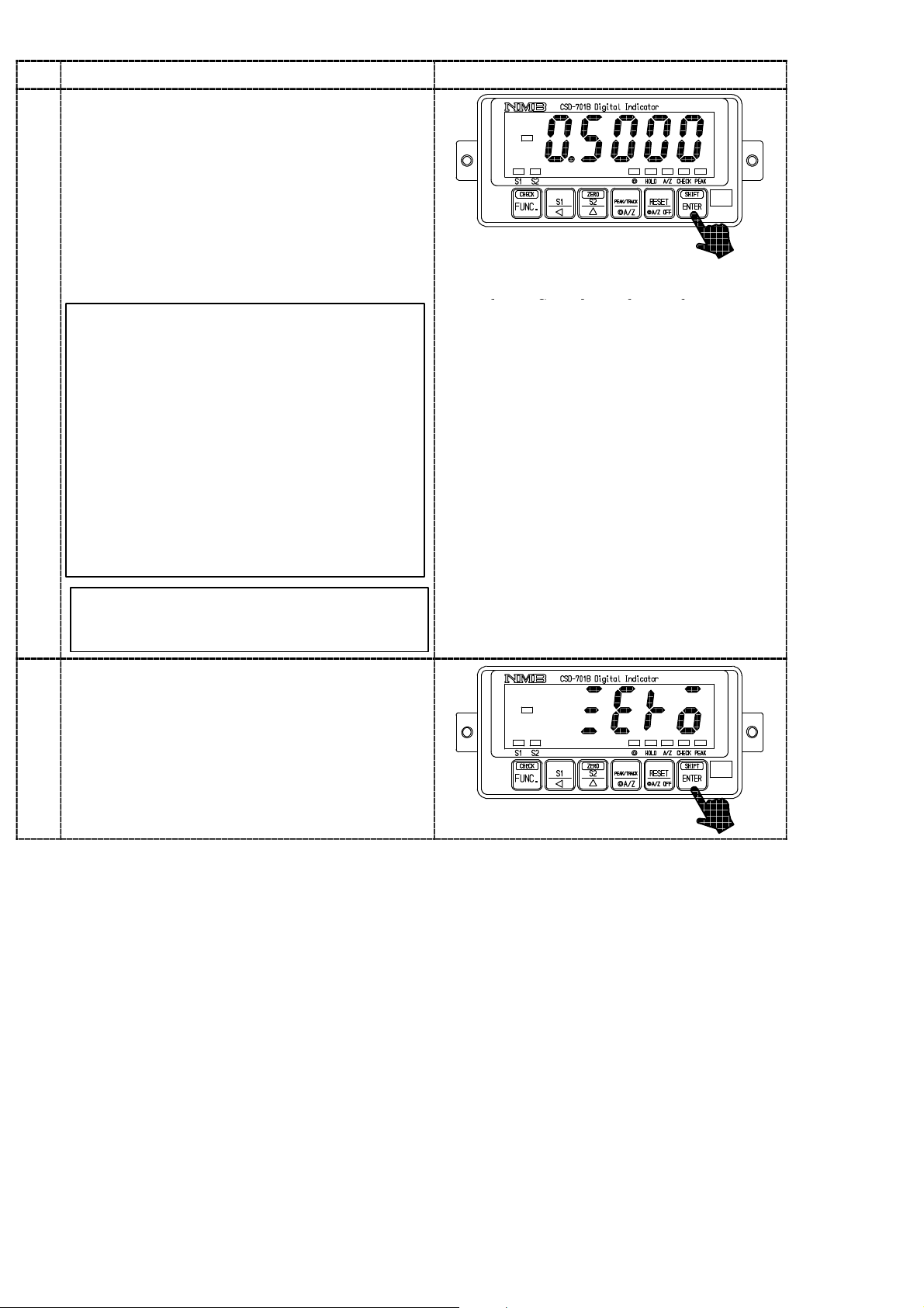
Press the key.
The load display will show “0.5000”, and the
digit of 10
In case that calibration has completed already,
the registered output value of load cell at that
time will be displayed.
Set the given value with the right keys, which is
subtracted the output value of load cell at the
time of initial load application from the output
value of load cell corresponding to the maximum
display value set in the step 6.
0
will flash on and off.
Though the number of digits has not
prepared in the “Inspection data” for load
8
cell so many as shown in the right figure,
extra digits are necessary for the
compensation with the standard point at
internal of the instrument.
In case of actual setting, insert “0”, into the
extra digits.
As for the value for extra digit, when tare
compensation and fine adjustment on load
are applied, it will be rewritten as a
compensated value automatically.
Setting range for the output of load cell is
from 0.400 0 mV/V to 3.100 0 mV/V.
key :Set value carry key
key :Set value inclement key
key :Set value initialization key
It can be increased continuously by the
continuity press of the key.
Press the key.
The load display will show “ZERO”.
Here, set the instrument with initial load
application.
9
22
Page 36

Procedures
Press the key.
The load display will show “ZERO” with lighting
display on and off, then zero adjustment can be
started.
Warning :At the same time, take care not
to apply load variation due to vibration and
so on. When load variation is applied, there
10
will be possibilities that zero point is
unstable, and precise reading of zero will
not be obtained.
After completed, the load display will become
“END”.
However, when the initial load is not entered
within the range from −0.3 mV/V to 2.4 mV/V,
the error code shown in the right figure will
show for about 2 seconds, then load display will
show “ZERO” and return to step 9.
TE−L :Zero point −OVER
TE−H :Zero point +OVER
Press the key.
After “CCAL” mode is over, the load display will
showthepresent load.
11
Error Code
Error Code
23
Page 37

5−2−2. Calibration procedures to register the output of strain gage applied transducer at the
time of zero and the maximum display
(1) Procedure by key operation
Warning ● Before using a new instrument or exchanging the strain gage applied
transducer for a new one, be sure to make calibration.
If calibration shall not be made, correct measured results may not be
obtained nor may cause malfunction in the instrument and there may
exist damage in peripheral equipments.
Besides, even though calibration has been made, there may occur the
similar case when the result is not correct, so make calibration again.
● During the calibration is executing, be sure to set Tare weight
cancellation clear, and to make cancellation (Execution of F−98) for
compensated data on zero set and set the OFF position of Zero
tracking(Setting “00000” on F−07 and F−08), and also set the OFF
position of Peak.
If neglected, correct measured results may not be obtained.
● During calibration procedures, press the key in case of
interrupting the calibration is required. The calibration data will be
kept as they are before entering the calibration and then returns to
the Measurement mode.
● Every time the key is pressed with the load display of “FUNC”,
the display will change as the following arrow marks. However, every
time the
direction of the following arrow marks.
“FUNC”→“CCAL”→“ACAL”→“LCAL”→“ZERO”→“SPAN”→
“TARE”→“CHEK”→“MONT”→“VCAL”→“VADJ”→“FUNC”→
“CCAL”→・・・・・ (Hereinafter, it will repeat.)
is pressed, the display will change as the reverse
24
Page 38

Procedures
Press the key for about one second
The load display will show “FUNC”.
1
Press the key twice.
It will make the load display proceed as
“FUNC”→“CCAL”→“ACAL”.
2
Press the key.
“ACAL” mode can be entered, then the load
display will show “SCAL”.
3
Press the key.
The load display shows “D−01”.
When the calibration has completed already, the
set value of minimum scale which has registered
at that time will be displayed.
4
Set the minimum scale with the right keys.
Setting value for the minimum scale will be 4
(four) as follows:
1, 2, 5, 10
Press the key.
The load display will show “DISP”.
5
key :Set value inclement key
25
Page 39

Procedures
Press the key.
The load display shows “2000” and the minimum
display digit will flash on and off.
When the calibration has completed already, the
maximum display value which has registered at
that time will be displayed.
By the setting of minimum scale, the digit
of minimum display that flashes on and off
will be as follows:
The minimum scale 1,2,5 10
The minimum scale 10 10
Set the maximum display value with the right
keys. Setting range for the maximum display
value will be (the minimum scale×100)〜99 990.
In order to make effective use of the performance,
6
set within the following ranges.
When setting is made over the range as below,
there may have a possibility of unstable display
and so on.
Setting range for the
maximum display value
100〜10 000
200〜20 000
500〜50 000
The minimum scale
1
2
5
0
digit
1
digit
key :Set value carry key
key :Set value inclement key
key :Set value initialization key
1 000〜99 990
It can be increased continuously by the
continuity press of the key.
Press the key.
The load display will show “Z MV”.
7
10
26
Page 40

Procedures
y
:
y
8
extra
digits
are
necessary
for
the
key:Set
value
initialization
key
Press the key.
The load display will show “0.0000”, and the
digit of 10
calibration has completed already, the registered
output value of load cell at that time will be
displayed.
Set the output value for load cell with the initial
load application with the right keys.
0
will flash on and off. In case that
Though the number of digits has not
prepared in the ”Inspection data” for load
cell so many as shown in the right figure,
compensation with the standard point at
internal of the instrument.
In case of actual setting, insert “0”, into the
extra digits.
As for the value for extra digit, when tare
compensation and fine adjustment on load
are applied, it will be rewritten as a
compensated value automatically.
Setting range for the output of load cell is
from −0.3 mV/V to 2.400 0 mV/V.
key :Set value carry key
key :Set value inclement key
ke
Setvalue initialization ke
It can be increased continuously by the
continuity press of the key.
Press the key.
The load display will show “S MV”.
9
27
Page 41

Procedures
yyy
Press the key.
The load display will show “0.5000” and the digit
0
will flash on and off.
at 10
In case that calibration has completed already,
the registered output value of load cell at that
time will be displayed.
The output value of the load cell which
corresponds to the maximum indicated value set
according to the procedure 8 is set with the right
keys.
key :Set value carry key
The set value to be set here should be
0.4 mV/V or more than the set value in the
step 8.
10
Though the number of digits has not
prepared in the Inspection data for load cell
as many as the digits in the right figure,
extra digits are necessary for the
compensation for the internal standard
point of the instrument.
In case of actual setting, insert “0” into the
extra digits.
As for the value of extra digits, when tare
compensation and fine adjustment on load
are applied, it will be written as a
compensated value automatically.
It can be increased continuously by the
continuity press of the key.
Press the key.
The load display will show the “END”.
11
key :Set value inclement key
key :Set value initialization key
Press the key.
After “ACAL” mode is over, the load display will
show the present load.
12
28
Page 42

5−2−3. Calibration method to register by reading output value of strain gage applied
transducer in the conditions of zero/actual load application individually.
(1) Procedures by the key operation
Warning ● Before using a new instrument or exchanging the strain gage applied
transducer for a new one, be sure to make calibration.
If calibration shall not be made, correct measured results may not be
obtained nor may cause malfunction in the instrument and there may
exist damage in peripheral equipments.
Besides, even though calibration has been made, there may occur the
similar case when the result is not correct, so make calibration again.
● During the calibration is executing, be sure to set Tare weight
cancellation clear, and to make cancellation (Execution of F−98) for
compensated data on zero set and set the OFF position of Zero
tracking(Setting “00000” on F−07 and F−08), and also set the OFF
position of Peak.
● During calibration procedures, press the key in case of
interrupting the calibration is required. The calibration data will be
kept as they are before entering the calibration and then returns to
the Measurement mode.
● Every time the key is pressed with the load display of “FUNC”,
the display will change as the following arrow marks. However, every
time the is pressed, the display will change as the reverse
direction of the following arrow marks.
“FUNC”→“CCAL”→“ACAL”→“LCAL”→“ZERO”→“SPAN”→
“TARE”→“CHEK”→“MONT”→“VCAL”→“VADJ”→“FUNC”→
“CCAL”→・・・・・ (Hereinafter, it will repeat.)
29
Page 43

Procedures
Press the key for about one second.
The load display will show “FUNC”.
1
Press the key three times.
It will make the load display proceed as
“FUNC”→“CCAL”→“ACAL”→“LCAL”.
2
Press the key.
“LCAL” mode can be entered, then the load
display will show “SCAL”.
3
Press the key.
The load display shows “D−01”.
When the calibration has completed already, the
set value of minimum scale registered at that
time will be displayed.
4
Set the minimum scale with the right keys.
Setting value for the minimum scale will be 4
(four) as follows:
1, 2, 5, 10
Press the key.
The load display will show “DISP”.
5
key :Set value inclement key
30
Page 44

Procedures
Press the key.
The load display shows “2000” and the minimum
display digit will flash on and off.
When the calibration has completed already, the
maximum display value which has registered at
that time will be displayed.
By the setting of minimum scale, the digit
of minimum display that flashes on and off
will be as follows:
The minimum scale 1,2,5 10
The minimum scale 10 10
0
1
digit
digit
key :Set value carry key
key :Set value inclement key
Set the maximum display value with the right
keys. Setting range for the maximum display
value will be (the minimum scale×100)〜99 990.
In order to make effective use of the performance,
6
set within the following ranges.
When setting is made over the range as below,
there may have a possibility of unstable display
and so on.
Setting range for the
maximum display value
100〜10 000
200〜20 000
500〜50 000
1 000〜99 990
The minimum scale
1
2
5
10
It can be increased continuously by the
continuity press of the key.
Press the key.
The load display will show “LOAD”.
key :Set value initialization key
7
31
Page 45

Procedures
pp
The
load
value
applied
on
the
load
cell
should
be
key:Setvalueinitializati
y
Press the key.
The load display will show “2000”, and the digit
0
will flash on and off.
of 10
In case that calibration has completed already,
the registered output value of load cell at that
time will be displayed.
By thesettingof minimum scale, thedigit
of minimum display that flashes on and off
will be as follows:
The minimum scale 1,2,5 10
8
The minimum scale 10 10
0
digit
1
digit
key :Set value carry key
Set the actual load value going to apply on the
load cell with the right keys.
The load value a
less than the maximum display value set in the
step 6 and should be the maximum load that can
apply on the load cell with the range of (the
minimum scale ×100)〜99 999 as well.
lied on theload cell shouldbe
It can be increased continuously by the
continuity press of the key.
Press the key.
The load display will show “ZERO”.
Here, set the initial load application.
9
key :Set value inclement key
onke
32
Page 46

Procedures
e
Press the key.
The “ZERO” on load display will flash on and
off, and zero adjustment can be started.
Warning :Take care not to apply load
variations due to vibrations and so on.
If load variation is applied, the zero point
will not stabilized, in due course there is a
possibility that correct reading of zero
won’t be obtained.
When completed, the display on the load display
will show “SPAN”.
However, when the initial load is not entered the
10
range of −0.3 mV/V to 2.4 mV/V, the right Error
code will be shown for about 2 seconds, then the
display on the load display section will be shown
as “ZERO”, and then the procedure 9 can be
entered.
TE−L:Zero point −OVER
TE−H:Zero point +OVER
Error code
Apply thesame load on theload cell as setin th
11
step 8.
Error code
33
Page 47

12
Procedures
Press the key.
The “SPAN” on the load display will flash on
and off, and span adjustment can be started.
Warning :Take care not to apply load
variations due to vibrations and so on.
If load variation is applied, the span will
not stabilized, in due course there is a
possibility that correct reading of span
won’t be obtained.
When completed, the display on the load display
will show “END”.
However, when the value corresponding to the
maximum display value does not satisfy the
range from 0.4 mV/V to 3.1 mV/V, the right
Error code will light up for about 2 seconds, then
the display on the load display section will show
“SPAN”, and then returns to the step 10.
SP−L:Span − Over
SP−H:Span + Over
Error code
Press the key.
After “LCAL” mode is over, the load display will
showthepresent load.
13
Error code
34
Page 48

5−2−4. Zero fine adjustment
(1) Procedures by key operation
● During the Tare weight cancellation(A/Z) or Zero set is executed, and
also during effective for Zero tracking and Peak ON, Zero fine
adjustment mode can’t be entered into. (Displays ER−5.)
The Zero fine adjustment can be entered after Tare weight
cancellation clear(A/Z OFF), cancellation of the Compensated data at
Zero set (Execution of F−98), set OFF the Zero tacking (Set the
F−08 and F−09 to “00000”.) and set the Peak OFF.
● During the calibration procedure, press the key to interrupt the
calibration. The calibration data will keep the same condition as it is
entered before, then returns to the Measurement mode.
● When the key is pressed with the load display of “FUNC”, the
display will change as the following arrow marks indicate at every
time the key is pressed. However, every time the is pressed, the
display will change as the reverse direction of the following arrow
marks.
“FUNC”→“CCAL”→“ACAL”→“LCAL”→“ZERO”→“SPAN”
→“TARE”→“CHEK”→“MONT”→“VCAL”→“VADJ”→“FUNC”
→“CCAL”→・・・・・(Hereinafter, it will repeat.)
Procedures
Press the key for about one second.
The load display will show “FUNC”.
1
Press the key four times.
It will make the load display proceeded as
“FUNC”→“CCAL”→“ACAL”→“LCAL”
→“ZERO”.
2
Here, set the initial load application.
35
Page 49

Procedures
5
Press the key.
Zero fine adjustment mode can be entered, then
the display on load display will show the present
load value and lights on and off. At the same
time, set the present load value to “0” with the
right keys.
It can be increased continuously by the
3
continuity press of the key.
key :Zero fine adjustment
display decreasing key
The variation of load value for one push of
the right key is less than 1 digit of display.
Therefore, a few pushes of these keys are
required to get the change of 1 digit of
display value.
Press the key.
The indication of load display will show “END”.
4
Press the key.
After quitting from zero fine adjustment mode,
the load display will show the present load value.
key :Zero fine adjustment
display increasing key
36
Page 50
5−2−5. Span fine adjustment
(1) Procedures by key operation
● During the Tare weight cancellation(A/Z) or Zero set is executed, and
also during effective for Zero tracking and Peak ON, Span fine
adjustment mode can’t be entered into. (Displays ER−5.)
The Span fine adjustment can be entered after Tare weight
cancellation clear(A/Z OFF), cancellation of the Compensated data at
Zero set (Execution of F−98), set OFF the Zero tacking (Set the F−08
and F−09 to “00000”.) and set the Peak OFF.
● During the calibration procedure, press key to interrupt the
calibration. The calibration data will keep the same condition as it is
entered before, then returns to the Measurement mode.
● When the key is pressed with the load display of “FUNC”, the
display will change as the following arrow marks indicate at every
time the key is pressed. However, every time the is pressed, the
display will change as the reverse direction of the following arrow
marks.
“FUNC”→“CCAL”→“ACAL”→“LCAL”→“ZERO”→“SPAN”
→“TARE”→“CHEK”→“MONT” →“VCAL”→“VADJ”→“FUNC”
→“CCAL”→・・・・・(Hereinafter, it will repeat.)
Procedures
Press the key for about one second.
The load display will show “FUNC”.
1
Press the key five times.
It will make the load display proceeded as
“FUNC”→“CCAL”→“ACAL”→“LCAL”
→“ZERO”→“SPAN”.
2
Please give the maximum load which can be
applied to the load cell here below the maximum
indicated value.
37
Page 51

Procedures
5
Press the key.
Span fine adjustment mode can be entered, then
the display on load display will show the present
load value and lights on and off. At the same
time, adjust the present load value to be the same
load applied on the load cell with the right keys.
It can be increased continuously by the
3
continuity press of the key.
The variation of load value for one push of
the right key is less than 1 digit of display.
Therefore, a few pushes of these keys are
required to get the change of 1 digit of
display value.
Press the key.
The indication of load display will show “END”.
4
key :Span fine adjustment
display decreasing key
key :Span fine adjustment
display increasing key
Press the key.
After quitting from zero Span fine adjustment
mode, the load display will show the present load
value.
38
Page 52
5−2−6. Calibration procedure to apply registration again for zero point only
(1) Procedures by key operation
Warning ● During the execution of calibration, be sure to set the Tare weight
cancellation clear, cancellation of the Compensated data at Zero set
(Execution of F−98), and set OFF the Zero tacking (Set the F−08 and
F−09 to “00000”.) and set the Peak OFF.
● During the calibration procedure, press the key to interrupt the
calibration. The calibration data will keep the same condition as it is
entered before, then returns to the Measurement mode.
● When the key is pressed with the load display of “FUNC”, the
display will change as the following arrow marks indicate at every
time the key is pressed. However, every time the is pressed, the
display will change as the reverse direction of the following arrow
marks.
“FUNC”→“CCAL”→“ACAL”→“LCAL”→“ZERO”→“SPAN”
→“TARE”→“CHEK”→“MONT” →“VCAL”→“VADJ”→“FUNC”
→“CCAL”→・・・・・(Hereinafter, it will repeat.)
Procedures
Press the key for about one second.
The load display will show “FUNC”.
1
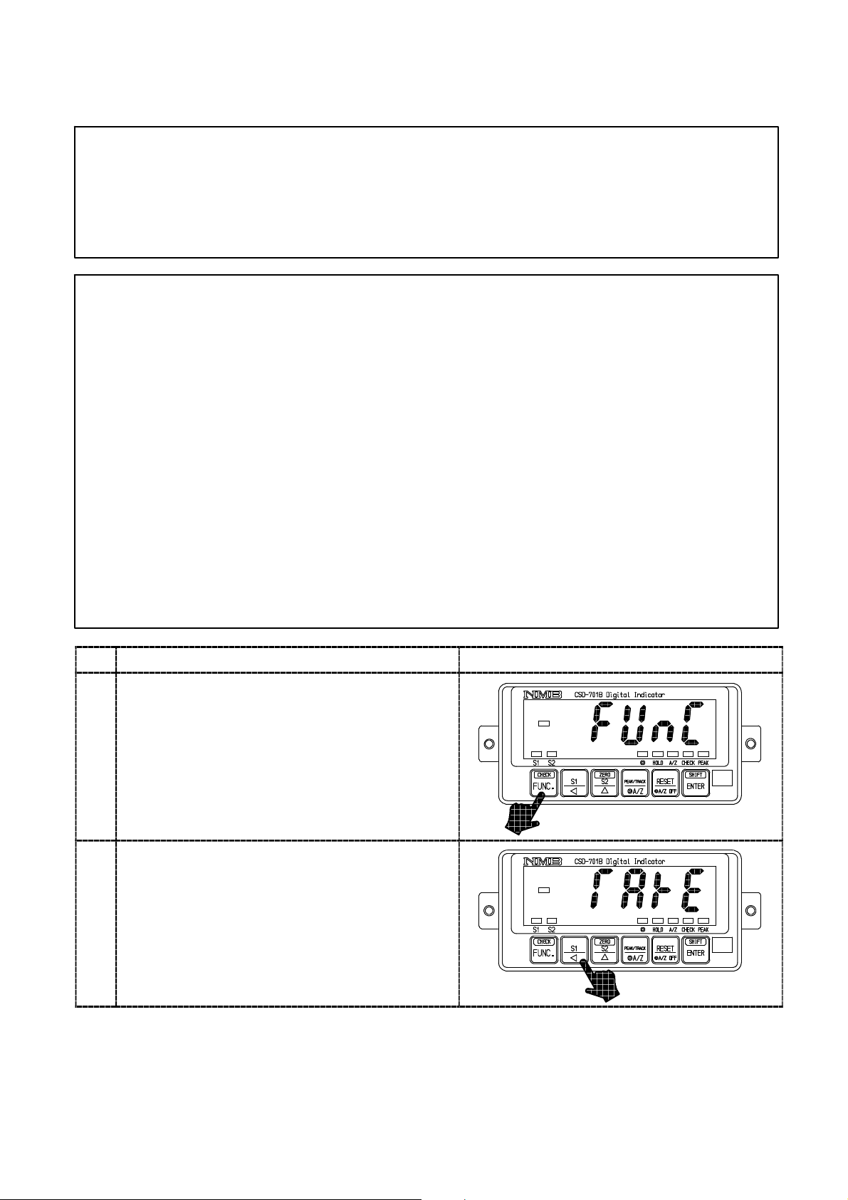
Press the key six times.
It will make the load display proceeded as
“FUNC”→“CCAL”→“ACAL”→“LCAL”
→“ZERO”→“SPAN”→“TARE”.
2
Here, set the initial load application.
39
Page 53

Procedures
Press the key.
The “TARE” mode can be entered.
The display on the load display section will show
“ZERO”.
3
Press the key.
The display of “ZERO” on the load display
section will flash on and off, and Tare weight
cancellation will be entered.
Warning :At the same time, care should
be taken not to apply load variation due to
vibration and so on.
If load variation is applied, zero point
becomes unstable, so there is a possibility
that correct zero can’t be read.
When completed, the indication of load
display will show “END”.
However, when the initial load isn’t entered
4
within the range of −0.3 mV/V and 2.4 mV/V,
the error code in the right will be shown for
about 2 seconds, then the display on the load
display will show “TARE”, and returns to the
step 2.
TE−L:Zero point −OVER
TE−H:Zero point +OVER
Press the key.
After quitting from the “TARE” mode, the load
display will showthepresent load value.
5
Error code
Error code
40
Page 54

5−3. Selection of calibration methods on each condition
The instrument prepares calibration methods shown in the paragraph in **タグなし**.
Calibration procedures, we’ll explain some conditions to execute actual calibration here.
(1) When executing calibration on the new instrument.
(In case that Combined Inspection at Minebea has not executed.)
D When load condition and output condition of load cell are clarified.
(Required accuracy is less than 1/1 000 or so.)
→Proceed to the paragraph 5−3−1(1)
D When load condition and output condition of load cell are clarified.
(Required accuracy is more than 1/1 000 or so.)
→Proceed to the paragraph 5−3−1(2)
D When load condition is clarified, but output condition of load cell is unclear.
→Proceed to the paragraph 5−3−1(3)
D When exchanging with existing CSD−701B is required.
→Proceed to the paragraph 5−3−1(4)
(2) When making calibration again.
D When calibration only for tare weight is required.
(In case that the combined Inspection at Minebea has already executed, and the calibration
only for tare weight is required.)
D When fine adjustment on zero and span is required.
5−3−1. In case of executing the calibration on the instrument newly.
When the new instrument is purchased or reuse is desired with the new specific conditions,
execute the calibration with whichever procedure as follows:
(1) When the load condition and the output condition of load cell are clarified.
(In case of desired accuracy is less than 1/1000 or so.)
Warning ● The calibration accuracy obtained in this procedure is less than
1/1 000 or so. When precise accuracy more than 1/1 000 is necessary,
make calibration with actual load according to the paragraph 5−3−1
(2).
Besides, the accuracy described here is a combined accuracy of the
instrument and the strain gage applied transducer connected.
If there may exist another factors of error such as mechanical
elements and so on, it will become out of warranty, so care should be
taken fully.
● The rated output value for load cell applicable by the calculation
should be assumed as the value described on the “Inspection data”
individually.
41
Page 55

5−2−1For example, we will show the calibration procedures as follows, that is, 3 points of load
cells with 3 mV/V of rated output and 5 t of rated capacity.
Tare weight 1.5 t
Weighing capacity 5 t
Maximum display 5 000
1
Calculate the output of load cell at maximum display from the above conditions. Check that
the calculated value should be within the range from 0.4 mV/V to 3.1 mV/V. If the value is out
of the range, calibration can’t be executed.
(Output of load cell at maximum display)
(Rated output)+(Rated output)+(Rated output)
=
3 mV/V+3 mV/V+3 mV/V
=
1 mV/V
=
2
After making the load cell to the initial load condition (tare weight), execute the calibration
according to the paragraph 5−2−1. In this case, input “5000” in the step 6, and input “1.0000”
in the step 8 individually.
3
If necessity requires, apply zero/span fine adjustment according the paragraph 5−2−4, and
5−2−5.
(2) When the both conditions of load and the output of load cell are clarified.
(In case that required accuracy is more than 1/1 000 or so.)
Number of load cells
3 points
×
3 points×5t
5t
×
(No. of load cells)×(Rated load)
Weighing capacity
Warning ● The accuracy obtained through the procedures of this calibration
consists from combined accuracy with the instrument and combined
strain gage applied transducer, the accuracy of weight used during the
calibration, error factors on mechanical and also error factors on
calibration works, that is, the total accuracy of these. If high accuracy
is required, full considerations should be made on each factor. If
neglected, there will be a case that desired accuracy may not be
obtained, so care should be taken fully.
When high accuracy is required, actual load calibration by using the weight and so on are
required.
For example, we’ll show the calibration procedures in the following conditions, that is, 3 points
of load cell with 3 mV/V of rated output and 5 t of rated capacity.
Tare weight 1.5 t
Weighing capacity 5 t
Maximum display 5 000
42
Page 56

1
Calculate the output of load cell at the maximum display from the above conditions.
Check that the calculated value at this point is within the range from 0.4 mV/V to 3.1 mV/V.
If the value is out of the range, calibration cant’ be executed.
(Output of load cell at maximum display)
(Rated output)+(Rated output)+(Rated output)
=
Number of load cells
3 mV/V+3 mV/V+3 mV/V
=
1 mV/V
=
2
After making the load cell to the initial load condition (tare weight), execute the calibration
3 points
×
5t
3 points×5t
×
Weighing capacity
(No. of load cells)×(Rated load)
according to the paragraph 5−2−3. In this case, input “5000” in the step 6, and input the load
value applied on the load cell in the step 8 individually.
3
If necessity requires, apply zero/span fine adjustment according the paragraph 5−2−4, and
5−2−5.
(3) When the load condition is clarified but the output condition of load cell is not clarified.
In the case of using the existing load detecting section, and adopting the new digital indicator
only, it is necessary to execute calibration after checking the output of load cell when its
output is not clarified.
For example, followings are calibration procedures when weighing capacity is 5 t and the
others are not clarified.
1
Set the instrument in the monitor mode according to the paragraph 7−19. In this condition,
the output level of load cell connecting with the instrument can be monitored up to approx.
3.100 0 with the unit of mV/V.
2
After making the load cell section to the initial load condition (tare weight), record the display
value on load display. This value is the output of load cell at the time of initial load condition.
3
Record the display value on load display after applying 5 t load on the load cell section. This
value is the output of load cell with weighing capacity applied.
4
4. From the load cell output at the time of initial load application recorded at ②, and load cell
output recorded at ③ at the time of application of weighing capacity, output of load cell at the
time of maximum display can be calculated according to the below formula.
Check that the calculated value is within the range from 0.4 mV/V to 3.1 mV/V. The
calibration can’t be executed if the value is out of the range.
(Output of load cell at the time of maximum display)
=(Output of load cell at weighing capacity)−(Output of load cell at initial load application)
5
Quit the monitor mode of the instrument.
6
After making the load cell to the initial load condition (Tare weight), execute calibration
according to the paragraph 5−2−1. In this case, the accuracy is less than 1/1 000 or so.
At this moment, input each value, “5000” in the step 5 and another input is the value of
“Output of load cell at the maximum display” calculated from the ④ in the step 8. If the
accuracy more than of 1/1 000 or so is required, execute calibration according to the paragraph
5−2−3. And at the same time, input “5000” in the step 6 and also input “Load value going to
apply on load cell” in the step 8 individually.
7
As necessity requires, make fine adjustment on Zero and Span according to the paragraph
5−2−4 and 5−2−5.
43
Page 57

(4) 5−3−1When replacing the existing CSD−701B with a new one.
Warning ● The accuracy in this procedure is less than 1/1 000 or so.
If higher accuracy is required, make calibration by using the actual
load according to the paragraph 5−3−1(2).
Moreover, the accuracy described here is a combined accuracy with the
instrument and strain gage applied transducer connected.
When another error factors may exist, such as constructional error
factors or so, it will become out of warranty for accuracy, so care
should be taken fully.
When the load at the section of load cell can’t make it with initial load application due to
failure on the existing CSD−701B, execute calibration by referring to the procedures as below.
However, in case that the initial load condition can be obtained, make calibration according to
the procedures of (1) and (2).
1
According to the paragraph 8−1, read out and write down the function F−90 “Increment
value”, the F−91 “Maximum display value”, the F−93 “Zero calibration value”, and the F−94
“Span calibration value” in the existing CSD−701B.
2
According to the paragraph 4, replace the exiting CSD−701B with a normal instrument and
make connections.
3
After turning ON the normal instrument, make calibration according to the paragraph
5−2−2. In case of this, input the “Increment value” recorded at ① in the step 3, the
“Maximum display value” in the step 5 and the “Zero calibration value” in the step 7 and in
the same way, input “Span calibration value” in the step 9.
44
Page 58

5−3−2. When the calibration is executed again.
When purchasing a new instrument and the combined inspection has executed at Minebea,
however, the tare weight has changed, or fine adjustment on zero and span are required, make
calibration with whichever the following methods.
(1) Calculation on tare weight only
(When combined inspection has completed at Minebea and calibration on only tare weight is
required.)
When the initial load (tare weight) has changed after completing the calibration, or when the
combined inspection at Minebea has been made and the calibration only for the initial
load(tare weight) is required after the installation, proceed the calibration in the following
steps.
1
After setting the initial load (tare weight) on load cell section, execute calibration according to
the paragraph 5−2−6.
(2) In case of executing fine adjustment on zero and span
Make adjustment according to the paragraph 5−2−4(Fine adjustment on zero), and 5−2−5
(Fine adjustment on span).
Warning ● The accuracy obtained through the calibration procedures consists
from combined accuracy with the instrument and strain gage applied
transducer, the accuracy of weight used during the calibration, error
factors on mechanical and also error factors on calibration works, that
is , total accuracy of these.
If high accuracy is required, full considerations should be made on
each factor. If neglected, there will be a case that the desired accuracy
shall not be obtained.
5−4. Setting the prohibition against calibration
After completing all of the calibration procedures, setting can be made to prohibit any more
calibration again by setting the funciton(Related function F−97).
For details, refer to the paragraph 7−17.
45
Page 59

6. Operation procedure
We’ll show the operating procedures with keys located on the front panel.
Warning ● Each key operation should be made after interrupting the
measurement. If it is made during measurement, it may cause an
unexpected malfunction.
● Key operation in Measurement mode can be effective by pressing it for
about one second or so.
6−1. key
6−1−1. Operations in Measurement mode
(1) When it is operated alone.
The Function mode can be entered, and the “FUNC” is shown on the load display section.
In this condition, setting on the Function or shifting to another modes can be available.
(2) When it is operated while the press of key.
If you will operate while the press of
on, and “CHECK” in the condition display section lights. At the same time, the load value
which corresponds to the value set in the load indicated value with F−11 is added.
After operating while the press of
former status.
6−2. key
6−2−1. When operating in the measurement mode
The set value of comparator S1 is displayed at the same time as S1 LED blinking, 100digits
blink, and setting the set value of comparator S1 becomes possible.
Moreover, the display automatically returns to the measurement mode when leaving without
operating key of anything under such a condition for about 20 seconds.
The changed set value is registered internally when do the press of
comes off the status where the S1 set value can be set.
key, the CHECK value set in function F−11 is turned
key, the CHECK value is turned off, and returns to the
key, and the operation
46
Page 60

6−2−2. Operation is made in another mode
(1) Carrying up the set value.
By pressing the
flashing digits for set value will carry up from 10
(However, the range of carry differs depending on the number of digits of set values and yes/no
of polarity sign.)
(2) Change of function and so on.
Executes change of various kinds of functions in Function mode, and also change of function
during Check mode.
(3) Decrement at the time of fine adjustment.
When the
analog output, the targeted value will decrease.
key with the condition of displaying various kinds of set values, the
0
,101,102,103to 104in order.
key is pressed at the time of making fine adjustment on ZERO, SPAN and
● In the operation method of the paragraph 6−2−2(3), when the key is
pressed for more than about 1 second, each operation will be executed
continuously at a constant interval without ON/OFF operation of the
key.
6−3. key
6−3−1. When operated in the Measurement mode.
(1) When it is operated alone.
At the same time the LED for S2 is flashing on and off, the Comparator S2 set value will
display and the 10
Comparator S2. And if you keep the instrument untouched for approx. 20 seconds, the
Measurement mode can be re−entered automatically. Pressing the key makes to register
the set values internally, then the condition of “Possible to set value for S2” can be over.
(2) When it is operated while the press of
If you operate while the press of
the display value in the load display section is within 10 % of the maximum indicated value
(Refer to the paragraph 5) and makes the display “0” compulsorily .
Please refer to details by the paragraph 7−12.
0
digit will flash on and off that makes to possible to set the set value for
key.
key, the zero set function works by this operation when
47
Page 61

6−3−2. When operated in another modes
(1) Increment of set value
By pressing the
value will increase per one count from 0, 1, 2, 3, 4, 5, 6, 7, 8, 9 and 0 again in order.
(2) Increment at the time of fine adjustment
When the
analog output, the targeted value will increase.
key with the condition of displaying various kinds of set values, the set
key is pressed at the time of making fine adjustment on ZERO, SPAN and
● In the operation method of the paragraph 6−3−2(2), when the key is
pressed for more than about 1 second, each operation will be executed
continuously at a constant interval without ON/OFF operation of the
key.
6−4. key
6−4−1. When operated in the Measurement mode.
(1) When the peak function is selected (Lighting off the Status display “◎”).
Changeover the display of peak value/track value.
(2) When the A/Z function is selected (Lighting up the Status display “◎”).
At the same time the Tare weight cancellation (A/Z) works and the load display value become
the net weight display value, the “A/Z” on the status display will light up and load display
becomes “0”.
6−4−2. When operated in another modes
(1) Calibration
The set value is initialized in each procedure of the calibration method.
(2) Function mode
In the function mode, the function number and the set value of the function are compulsorily
made “0”.
(3) Comparator setting
The set value is compulsorily made “0” with the set value of the comparator can set.
48
Page 62

6−5. key
6−5−1. When operated in the Measurement mode
(1) When the peak function is selected (Lighting off the Status display “◎”).
Set the display ”0”, and reset the peak value.
(2) When the A/Z function is selected (Lighting up the Status display “◎”).
At the same time the Tare weight cancellation clear(A/Z OFF) works and the load display
value become the gross weight display value, the “A/Z OFF” on the status display will light up.
6−5−2. When operated in another modes.
When the key is pressed while entered in various kinds of modes, you can shift to the
Measurement mode.
6−6. key
Pressing the key makes to register the set values internally, then the condition of “Possible to
set” will be over.
49
Page 63

7. Function and operation
7−1. External control input signal and contact output signal
The instrument is available to the external control through various kinds of input signals.
7−1−1. Input signal for external control
Activates by shortening with COM.1 (Terminal No. 8).
Terminal
No.
9 ZERO When the indicated value on load display is within 10 % against the
10 HOLD While inputting the signal, the target selected with Function F−10
11 PEAK
12 RESET
8 COM.1 The common for the input signal (Terminal No. 9 to 12)
Name Operation
maximum display value, zero set function will activate by the
operation and make the display “0” compulsively. (Same key
operation in the paragraph 6−3−1.) As for the operational details,
refer to the paragraph 7−12.
among display, contact output, analog output and options will be
frozen. As for the operational details, refer to the paragraph 7−9.
Changeover of track value and peak holding value.
/TRACK
/A/Z
/A/Z OFF
Moreover, when the A/Z function is selected with F−70, it executes
the tare weight cancellation.(A/Z ON)
Open :Track value
Short:Peak holding value
During the peak hold operation, the reset condition is made by short
circuit. And tare weight cancellation clear(A/Z OFF) when A/Z
function is selected with F−70.
● Operation of input signal will be executed after shortening for more
than 100 ms approximately.
● Only A/Z and the A/Z OFF function are pulse input, and it is effective
once in the pulse width of 100 ms or more.
● When the ZERO signal(or the + key on the front panel) is
input while inputting the HOLD signal, the operation of ZERO is
executed simultaneously with the release of the HOLD signal.
● When the HOLD signal is input in the status of power supply OFF,
and the power supply is turned on, it is displayed in load display panel
as “HOLD”. The load is displayed simultaneously with the release of
the HOLD signal.
● The COM. 1 (terminal No. 8) and the COM.2 (terminal No. 13) are
isolated.
50
Page 64

7−1−2. Contact output signal
Terminal
No.
14 S1 The contact output for comparator S1. 1a contact.
15 S2 The contact output for comparator S2. 1a contact.
13 COM.2 The common for the contact output(terminal No.14 to No.15).
Name Operation
● COM.1 (terminal No. 8) and COM.2 (terminal No.13) are insulated.
● The comparator of the instrument executes the comparison operation
synchronizing with the display.
● The delay time starting from preparing the output conditions to the
contact output ON, will be 5 ms approximately.
7−1−3. Equivalent circuit
(1) External control input section
+5V
to the inside
+5V
2.2 kΩ
2.2 kΩ
200 Ω
INPUT
COM.1
(2) Contact output section
AC125 V 0.1 A (Resistance load)
DC30 V 0.5 A (Resistance load)
OUTPUT
COM.2
51
Page 65

7−2. Comparator
The instrument provides with the comparator by two set values of S1 and S2.
● The comparator of the instrument executes the comparison operation
synchronizing with the display.
7−2−1. ON/OFF of comparator S1 and S2
Operational selection of ON/OFF can be made for each comparator S1 and S2. These selections
are done by the function (related function F−30). Default has selected both S1 and S2 turning
on.
7−2−2. Change of set value
Warning ● When the set value for the comparator is set wrong, or set in the
wrong procedures, it may not obtain the correct results from the
comparator, and it may cause malfunctions in peripheral equipments
and also cause a damage as well.
Procedures
Change of S1 set value
In the Measurement mode, pressing the
makes the 10
on the front panel load display will flash on and
off, then change of S1 setting can be available.
Every time the
digit will change from 10
2
digit→103digit→104digit→Polarity(POL)→
10
0
digit.
10
1
Change the set value by the
flashing the digit which is desired to change.
0
digit and the judgement display S1
key is pressed, the flashing
0
digit→101digit→
key after
If you keep the instrument untouched for
approx. 20 seconds in the condition of change
of setting is available, the Measurement mode
can be re−entered automatically.
After fixing up the change, press the
Make the set value effective, then the
Measurement mode can be entered again.
key
:Set value carry key
:Set value inclement key
:Set value initialization key
(Make the set value to “0”.)
key.
52
Page 66
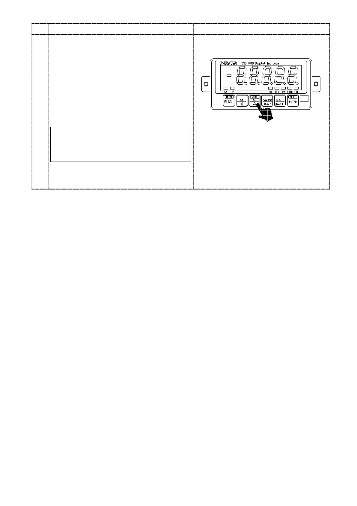
Procedures
Change of S2 set value
In the Measurement mode, pressing the
makes the 10
on the front panel load display flashing on and
off, then change of S2 setting can be available.
Every time the
digit will change from 10
2
digit→103digit→104digit→Polarity(POL)→
10
2
0
10
digit. Change the set value by the key
after flashing the digit which is desired to change.
0
digit and the S2 judgement display
key is pressed, the flashing
0
digit→101digit→
If you keep the instrument untouched for
approx. 20 seconds in the condition of change
of setting is available, the Measurement mode
can be re−entered automatically.
After fixing up the change, press the
Make the set value effective, then the
Measurement mode can be entered again.
key
:Set value carry key
:Set value inclement key
:Set value initialization key
(Make the set value to “0”.)
key.
53
Page 67

7−2−3. Operation on comparator S1 and S2
The comparator in the instrument, S1 and S2 can select the operation whichever “contact ON
at more than the set value”, or “contact ON at less than the set value”. This selection can be
made in the Function mode. (Related function F−32)
As for default, the “contact ON at more than the set value” is selected for both of S1 and S2.
Warning ● Depending on the operational selection for comparator, ON/OFF
condition for each contact output may differ. If wrong operation is
selected, ON/OFF condition for contact output becomes inadequate
and it may cause an unexpected accident due to malfunctions on
peripheral instruments, so care should be taken fully.
● When the load display is “OL” or “−OL”, the “display value” for the
comparison of comparator is assumed as “+∞(infinity)” and “−∞
(infinity)” individually.
Operation on judgement display section and contact output will be shown as an example of S1
below. The operation becomes similar as for S2.
(1) When the operation of “contact ON at more than the set value” is selected.
S1 judgement display, S1 contact output ON at (S1 set value)≦(Display value)
Display (small)
S1 set value
S1 judgement display,
S1 contact output
(2) When the operation of “contact ON at less than the set value” is selected.
S1 judgement display, S1 contact output ON at (S1 set value)≧(Display value)
Display (small)
S1 set value
S1 judgement display,
S1 contact output
Display (large)
Display (large)
ON
OFF
ON
OFF
54
Page 68

7−2−4. Comparative target for comparator S1 and S2
The comparator in the instrument, S1, S2 individually can select the comparative target from
the two, that is, “PEAK/Net weight”, “TRACK/Gross weight”. This selection can be made in the
Function mode. (Related function FUNC−31) As for default, the “TRACK/Gross weight” is
selected for both of S1 and S2.
Warning ● The ON/OFF condition of each contact output is different according to
the comparison target selection of the comparator. If wrong operation
is selected, ON/OFF condition for contact output becomes inadequate
and it may cause an unexpected accident due to malfunctions on
peripheral instruments, so care should be taken fully.
Operation on judgement display section each comparative target and the operation of contact
output will be shown as follows when the operation of “contact ON at more than the set value”
is selected by the S1, for an example. The same is the operation of S2.
(1) When the operation of “PEAK/Net weight” is selected.
S1 judgement display, S1 contact output ON at (S1 set value)≦(Display load)
Load display (small)
Load display (large)
S1 judgement display,
S1 contact output
(2) When the “TRACK/Gross weight” is selected.
S1 judgement display, S1 contact output ON at (S1 set value)≦(TRACK/Gross weight)
TRACK/Gross weight (small)
S1 judgement display,
S1 contact output
S1 set value
ON
OFF
TRACK/Gross weight (large)
S1 set value
ON
OFF
55
Page 69

7−2−5. Hysteresis on comparator
Comparator S1 and S2 of the instrument can set the hysteresis because of the chattering
prevention of the output relay.
Hysteresis can be used by combining setting by the width of data and combining setting by the
time width. Moreover, effective directions of hysteresis can be selected from either ”Off delay” or
”On delay”.
These selections are done in the function mode (related function F−34, F−35, and F−36).
Default has set hysteresis “OFF”.
Warning ● Depending on the setting of comparator hysteresis, ON/OFF condition
for each contact output may differ. If wrong mode is selected, ON/OFF
condition for contact output becomes inadequate and it may cause an
unexpected accident due to malfunctions on peripheral instruments,
so care should be taken fully.
The operation of judgement display panel and the contact output when the hysteresis of the
comparator is set is shown as an example of S1 below.
The operation becomes similar as for S2.
(1) When the operation of “contact ON at more than the set value” is selected at S1 and also
effective direction for hysteresis is set as “On delay”.
Hysteresis time width
Hysteresis
Display
data width
S1 set value
Time
S1 judgement
display
S1 contact
output
ON
OFF
56
Page 70

(2) When the operation of “contact ON at more than the set value” is selected at S1 and also
effective direction for hysteresis is set as “Off delay”.
Hysteresis time width
S1 set value
Hysteresis
Display
data width
Time
S1 judgement
display
S1 contact
output
(3) When the operation of “contact ON at less than the set value” is selected at S1 and also
effective direction for hysteresis is set as “On delay”.
Hysteresis time width
ON
OFF
S1 set value
Hysteresis
Display
data width
Time
S1 judgement
display
S1 contact
output
ON
OFF
(4) When the operation of “contact ON at less than the set value” is selected at S1 and also
effective direction for hysteresis is set as “Off delay”.
Hysteresis time width
Hysteresis
Display
data width
S1 judgement
display
S1 contact
output
S1 set value
Time
ON
OFF
57
Page 71

7−3. How to use the filter
The instrument has the digital filter to which the data converted into digital is stabilized by the
calculation processing.
Warning ● When setting filter is not suitable, correct measurement can’t be made
and it may cause an unexpected accident, so care should be taken
fully.
7−3−1. Digital filter
The digital filter for the instrument can be set from “00000” to “00007”.
The averaged−out times of digital filter can be decided from the set value (Related function
F−04)
As for default, “00004” is selected.
The relations between the setting and the averaged−out times are as follows:
(Averaged−out times)=2
For example, when “00004” is selected, averaged out times is as follows:
(Averaged−out times)=2
The tendency to the characteristic by the leveling frequency is shown in the table below.:
n
4
=16(Times)
n:Set value
Averaged out times
Resist to noise rapid stable
Response speed quick slow
low high
7−4. Zero tracking
The instrument prepares the zero tracking in order to compensate for slow drift of zero.
● Effective only when the A/Z mode is selected. (Related function
F−70)
7−4−1. What is zero tracking?
D Zero tracking is a function to cancel the slow drift of zero within the constant conditions,
and also to follow the zero point of the instrument in order to stabilize zero point.
D When the data variation within the set time with function F−09 is within the set value set
with the function F−08 against the zero point, then the input will be cancelled as the zero
point. However, when the zero point compensation for the total “±10 % of the maximum
display value” at the zero tracking and zero set are completed until that time, the further
directional zero tracking will not executed.
58
Page 72

7−4−2. Setting related with zero tracking.
D Set the data width that performs zero tracking with the function F−08. The zero tracking
width per setting value “n” will be obtained by the calculation of display according to the
below formula.
(Zero tracking data width) =(Set value of F−08)×0.5×(Increment value for display)
For example, when the setting of function F−08 is “00010” and the increment value for
display is “D=5”, then (Zero tracking data width) will be as follows:
(Zero tracking data width) =10×0.5×5
=25D
D Set the time width performs zero tracking with the function F−08.
● The zero tracking will not operate whichever the function F−09 or the
function F−70 is set as “0”, or the function F−70 is “0”.
Zero tracking
+
data width
Zero tracking
−
data width
Display
Zero point
Setting of F−09
Setting of F−09
Less than F−09
Setting of F−09
Time
● When the load shows slow vibration in the vicinity of zero, never use
the zero tracking.
● When the variation of load display becomes moderate due to the
strength/weakness of the digital filter and stabilized filter, there may
have the case that the zero tracking becomes effective even when the
actual load variation is rapid, so care should be taken fully.
7−4−3. Cancellation for compensation by zero tracking
Cancellation for compensated data by zero tracking can be executed with the function F−98.
● When changing the target for zero tracking is required, be sure to
cancel the compensated portion by zero tracking once using the
function F−98.
The zero tracking of the instrument will become effective at the time of the load display will be
the gross weight. In due course, at the time of A/Z ON, the zero tracking will not work.
59
Page 73

7−5. Stabilized filter
The instrument prepares the Stabilized filter that can filter through digital filter strongly when
variable width for load is within the constant value and also the same condition is frozen for more
than a constant period.
7−5−1. What is the Stabilized filter?
When the variable width of load is within the set value by the function F−17 and also the same
condition is frozen for more than the set value with the F−16, the digital filter for stabilized
filter will become effective set with the function F−15. That is, the digital filter will be applied
only when the load is stable for more than a constant value, and then stabilizes the load display.
7−5−2. Setting related with the Stabilized filter.
D Set the data to apply the Stabilized filter with the function F−17. The stabilized filter
width per set value “n” can be obtained through the display conversion by using the
following formula.
[Stabilized filter data width]=[Set value of F−17]×[Display increment value]
For example, when the setting of function F−17 is “00010” and the display increment is
“D=5”, then
[Stabilized filter data width]=10×5
=50
D Data width supervisory time for the Stabilized filter can be set with the function F−16.
D The digital filter for Stabilized filter can be set with the function F−15.
D The averaged−out times for the digital filter for Stabilized filter per set value “m” can be
obtained by the following formula.
[Stabilized filter averaged−out times]=2
m
For example, when the setting of function F−15 is “00002”,
[Stabilized filter times]=2
2
=4(Times)
D Moreover, when the digital filter has set with the function F−04, the averaged−out times
will be “Stabilized filter averaged−out times” and “Averaged−out times” with the function
F−04. (Refer to the paragraph 7−3.)
That is,
[Averaged−out times]
=[Averaged−out times with the F−04]×[Averaged−out times of stabilized filter]
For example, setting for the function F−04 is “00004” and the function F−15 is “00002”
as well, it will be as follows:
[Averaged−out times]=2
4×22
=16×4
=64(times)
60
Page 74

Load
variation
width
Load
Stabilized filter
data width
Stabilized filter
time width
Stabilized filter
time width
Load variation
width
Stabilized filter
data width
Digital filter for
stabilized filter
Effective
Ineffective
7−6. Change of Peak function and A/Z function
We can use the instrument by selecting one whichever the “peak function” or the “A/Z function”.
This selection can be performed in the Function mode. (Related function F−70.)
Stabilized filter
time width
Load variation
width
Stabilized filter
data width
Time
61
Page 75

7−7. How to use the peak hold.
The instrument provides the peak holding function.
The maximum value of the load is held.
+
0
−
PEAK LED
key
PEAK/TRACK
input
key
HOLD input
ON
OFF
ON
OFF
ON
OFF
ON
OFF
ON
OFF
Load
Load display
Load display
during HOLD
● At the time of short of PEAK/TRACK input, the peak hold condition
will not change even if the key is pressed ON.
62
Page 76

7−8. Various functions concerning display
7−8−1. Selection of target of display
The instrument can select the display frequency from 4 times/s and 20 times/s. This selection is
done in the function mode (related function F−03). Default has selected 4 times/s.
● The comparator of the instrument executes comparative operation
synchronous with the display. Besides, the conversion of analog
output is synchronous with the display.
In due course, when changing of conversion times of comparator, and
also conversion times of analog output is/are required, execute the
change of display times with the function F−03.
7−8−2. Selection of position of decimal point display
The instrument can display the decimal point at the “Load display section” of the instrument.
The selection of display can be made in the Function mode. (Related function F−01) Default has
selected “No decimal point display”.
7−8−3. Load display range
The load display range for the instrument is fixed from the −10 % to 110 % of the maximum
display value at the time of setting during calibration. When less than the range, “−OL”
displays and over the range “OL” displays. For example, when the maximum display value is
“1 000”, the load display range will be from −100 to 1 100.
Besides, when under −100, the “−OL” displays, and over 1 100, the “OL” will display.
7−9. Selection the target for HOLD
The instrument can select the target for HOLD function among “load display”, “comparator
contact output of S1 and S2, LED display”, “Analog output” and “Options”.
This selection can be made in the Function mode(Related function F−10).
As for the default, “All is selected.” Layout of setting for the F−10 are as follows:
0
10
digit:Load display
1
10
digit:Contact output of comparator S1 and S2, LED display
2
10
digit:Analog output
3
10
digit:Optional output
※With the “0” setting, out of the target, and with “1” setting, target of HOLD.
● When HOLD target ”Load display” is selected, key, key and
key becomes invalid.
63
Page 77

7−10. Change of bridge power supply voltage
The instrument can select the bridge power supply from “5 V” and “2.5 V”. This selection can be
made in the Function mode(Related function F−12). Default has selected “5 V”.
● When the bridge power supply voltage is changed, please execute the
calibration again.
7−11. Tare weight cancellation (A/Z)
The instrument prepares Tare weight cancellation (A/Z) function.
Pressing the
display becomes net weight display, at the same time, the “A/Z” lights up on the status display and
load display value becomes “0”.
Moreover, when the
activate and at the same time when the load display value becomes gross weight, the “A/Z” on the
status display will put off.
key makes Tare weight cancellation (A/Z) function operated and when the load
key is pressed, Tare weight cancellation clear(A/Z OFF) function will
● When tare weight cancellation (A/Z) function is required, select
“00001:A/Z function effective” by function F−70.
Upon this selection, “◎” on the status display will be light on, and
A/Z function will be active.
7−12. Zero set
The instrument prepares zero set function.
When the display value on load display is within 10 % against the maximum display value (Refer to
the chapter 5.), by press of the
works and the display is made “0” compulsorily.
However, zero set will not be accepted when zero compensation for total ±10 % is executed with
zero set and zero tracking until that time. (ERR−0 display)
Also, the same operation can be made with the operation of “ZERO” at the input signal of external
control. Cancellation for data applied zero compensation by zero set can be executed with Function
F−98.
key together with the press of key, the zero set function
● When tare weight cancellation (A/Z) is executed (during A/Z display
lights up), zero set will not be accepted. It will display “ER−5”.
When zero set is desired to execute, execute after making the Tare
weight cancellation clear (A/Z OFF).
64
Page 78

7−13. Lock of key function
The instrument prepares the lock of key function.
With the Function F−06, execute the lock OFF of key function by setting each digit=0, and
executes lock ON of key funciton by setting each digit=1. As for default, “all is lock OFF of key
function”. Besides, the correspondence between the target of key funciton and setting digits are as
follows:
0
10
digit :ON/OFF of CHECK value(Press the key in the condition of pressing the
key.)
1
digit :ON/OFF of Peak Hold function, A/Z ON(), Reset of the peak value,
10
2
digit :Reading out the change mode of S1 setting(), Reading out the change mode of
10
3
10
digit :Execute the zero setting(Press the key in the condition of pressing the
4
digit :Reading out the function mode()
10
Moreover, when the reading out the function mode is locked, the function mode can be
proceeded after pressing the
key for over 1 second.
7−14. CHECK value
By press of key together with the press of key in the Measurement mode, CHECK value
equivalent to the set value with the Function F−11 will be ON. And at the same time when the “
CHECK” on status display lights up, the load value equivalent to the set value with Function F−11
will be added to the load display value. As for default, 0.4 mV/V has set.
A/Z OFF(
S2 setting(
key.)
)
)
key for over 2 seconds in the condition of pressing the
By press of the
and returns to the former condition as it is.
key together with the press of key again, the CHECK value will be OFF
● When the setting of Function F−11 is “00000”, load display value will
not vary even if the “CHECK” lights up on the status display.
(Because CHECK is 0.0 mV/V.)
65
Page 79

7−15. How to use the analog output
Warning ● When the power supply is turned on with shorting the external
HOLD signal, the analog output will be made as follows:
When the target of HOLD by F−10 is the analog output, the analog
output will become the minimum value.
● Be careful on the following point when CHECK function is used.
The “OL” error display(Analog output at OVR.) will be displayed by
making CHECK effective.
● The analog outputs for the instrument are 2 type of “Voltage output”
(Standard) and “Current output”(Optional).
● The analog output of the instrument executes re−writing the outputs
synchronous with the display.
● The resolution of the analog output of the instrument is approx.
1/10 000 against the voltage output from 0 V to 5 V, and the current
output from 4 mA to 20 mA.
● The analog output has possibility of the output variation when the
power is turned on. To take the stable condition, use the instrument
about one hour after the power has been turned on.
7−15−1. Scaling of analog output
The analog output for standard specifications is set between the minimum value and the
maximum value with the output of 0 to 2 000.
By changing the F−21 and F−22, optional value can be decided.
Analog output
Approx.24 mA
Approx.6.25 V
The maximum
value
20 mA
5V
−10 % of the
maximum display
The minimum
value
4mA
0V
0 display
Approx.0 mA
Approx.−1.25 V
The maximum
display
66
Display
+110 % of the
maximum display
Page 80

F−21 sets the display when the minimum value is desired to output.
F−20 sets the display when the maximum value is desired to output.
(Example) F−21:Set as 1 000
F−22:Set as 5 000
When the display is 5 000, the maximum value outputs.
When the display is 1 000, the minimum value outputs.
Analog output
Approx.24 mA
Approx.6.25 V
The maximum value
The minimum value
20 mA
5V
4mA
0V
1 000
Approx.0 mA
Approx.−1.25 V
5 000
Display
5 500
Warning ● Setting F−22 must not exceed the maximum indicated value set in
chapter 5.
● In F−21, please set smaller value than the value set with F−22.
If neglected, the correct output can’t be obtained.
7−15−2. Fine adjustment 1 on analog output
Fine adjustment described here, is the one to arrange each “the minimum value” and “the
maximum value” without applying the actual load during the procedures. Refer to the
paragraph 7−15−3, for the fine adjustment with actual load applied.
● During the application on fine adjustment, if you want to suspend,
press the key. The minimum value data and the maximum value
data are kept as they were before entering the fine adjustment, and
the Measurement mode can be re−entered.
● Please execute the fine adjustment after about one hour has passed
since the power supply was turned on. The fine adjustment can be
executed in the status of the stable or more.
67
Page 81

Procedures
Press the key for about one second.
The load display will show “FUNC”.
1
Press the key 9 times.
The load display will change as “FUNC”
→“CCAL”→“ACAL”→“LCAL”→“ZERO”
→“SPAN”→“TARE”→“CHEK”→“MONT”
2
→“VCAL”.
Press the key.
The load display will show “ALOW”.
3
Press the key.
The load display will flash on and off showing
“ALOW”.
At the same time, the analog output equivalent
to the minimum value of analog output will be
obtained.
Adjust so the output will become the minimum
value with the right keys.
4
Current output
(Optional)
Minimum
value
Voltage output
(Standard)
0V 4mA
It can be increased continuously by the
continuity press of the key.
key :Decrease the analog output
key :Increase the analog output
68
Page 82

Procedures
7
te
u/a u
output
o
aaog
output
Fine adjustment on the maximum value of
analog output
Press the key.
The load display will flashing display showing
5
“A_HI”.
Press the key.
The load display will flash on and off showing
“A_HI”.
At the same time, the analog output equivalent
to the maximum value of analog output will be
obtained.
Adjust so the output will become the maximum
value with the right keys.
6
Current output
(Optional)
Maximum
value
Voltage output
(Standard)
5 V 20 mA
key :Decrease the analog output
key :Increase the analog output
It can be increased continuously by the
continuity press of the key.
Press the key.
The load display will show “END”.
By pressing the
Measurement mode can be returned through the
VCAL mode, then the present load will be
shown.
At this moment, the result of fine adjustment on
the minimum/maximum output of analog output
can be renewed.
key again, the
69
Page 83

7−15−3. Fine adjustment 2 on analog output
The fine adjustment explained in this paragraph is the procedures with applying the actual
weight.
Warning ● Before making the fine adjustment, be sure to make scaling for the
analog output by referring to the paragraph 7−15−1.
If neglected, deviation of output can’t be adjusted during the fine
adjustment.
● During the application on fine adjustment, if you want to suspend the
fine adjustment, press the key. The zero data, the span data are
kept as they were before entering the fine adjustment, and the
Measurement mode can be re−entered.
● Please execute the fine adjustment after about one hour has passed
since the power supply was turned on. The fine adjustment can be
executed in the status of the stable or more.
Procedures
Press the key for one second.
The load display will show “FUNC”.
1
Press the key 10 times.
The load display will change as “FUNC”
→“CCAL”→“ACAL”→“LCAL”→“ZERO”
→“SPAN”→“TARE”→“CHEK”→“MONT”
2
→“VCAL”→“VADJ”.
Press the key.
The load display will show “ALOW”.
At the same time, set the weight equivalent to
the minimum output value of the analog output.
3
70
Page 84

Procedures
7
Press the key.
The load display will flash on and off showing
the current load value.
At the same time, adjust the deviation with the
right keys so the analog output will meet with
the actual weight.
4
It can be increased continuously by the
continuity press of the key.
Fine adjustment on the maximum value of
analog output
Press the key.
The load display will show “A_HI”.
5
At the same time, set the weight equivalent to
the maximum output value of the analog output.
key :Decrease the analog output
key :Increase the analog output
Press the key.
The load display shows the current load value
and flashes on and off.
At the same time, adjust the deviation of analog
output against the load with the right keys.
6
It can be increased continuously by the
continuity press of the key.
Press the key.
The load display will show “END”.
By pressing the
Measurement mode can be returned through the
VADJ mode, then the present load will be shown.
At this moment, the result of fine adjustment on
the minimum/maximum output of analog output
can be renewed.
key again, the
key :Decrease the analog output
key :Increase the analog output
71
Page 85

7−15−4. Selection of the target of analog output
The instrument can select the target of analog output from the “TRACK/gross load” and the
“PEAK/Net weight”.
This selection can be made in the Function mode(Related function F−20).
Besides, during the “Gross/TRACK” is selected, the target of analog output will become normal
“TRACK value” and normal “Gross weight” each, that is, at the time of selection of the “Peak
function” with the Function F−70 and also the “A/Z function” is selected each.
7−16. Memory location for setting data and so on
In the instrument, each data is recorded in RAM and EEPROM as follows:
Data is preserved when almost permanent. because of nonvolatile EEPROM.
Moreover, because RAM is not backed up, RAM data disappears in power supply OFF.
1
Data recorded in RAM
・A/Z data Data can clear with A/Z OFF.
・ZERO tracking data Data can clear by the F−98 execution.
2
Data recorded in EEPROM
・FUNC data Data can be initialized by the F−99 execution.
・Calibration data Data can be rewritten by the re−calibration.
・Fine adjustment data for the analog output
Data can be rewritten by the fine adjustment again.
・ZERO data Data can clear by the F−98 execution.
・Each set value for the comparator S0, S1 and S2
Data can clear by the change in each set value.
● The memory locations for the A/Z data and the ZERO data can be
changed to whichever the “RAM” or the “EEPROM” with the setting
Function F−71.
7−17. Prohibition of calibration
The instrument can set the prohibition of the calibration for the excessive calibration.
This setting can be made in the Function mode.
(Related Function F−97.) As for the default, “Possible to calibrate” has selected. The targets of
prohibition are each calibration described in the Chapter 5, and each fine adjustment on the analog
output described in the paragraph 7−15−2 and the paragraph 7−15−3.
When executing the calibration with the setting of Prohibition of calibration, the “ER−6” will be
displayed.
72
Page 86

7−18. Check mode
The following confirmations can be made in the Check mode.
・Check of ROM version
・Check of the mounting option
・Check of bridge voltage
・Check of the external control input
・Check of the contact output
・Check of the analog output
・Check of the BCD output (option)
● The check on the BCD output will be operated only when the BCD
output is installed.
● The instrument can return to the Measurement mode by pressing the
key even in the halfway of the Check mode.
7−18−1. Operating procedure for the check mode
● When the key is pressed with the load display of “FUNC”, the
display will change as the following arrow marks indicate at every
time the key is pressed. However, every time the key is pressed,
the display will change as the reverse direction of the following arrow
marks.
“FUNC”→“CCAL”→“ACAL”→“LCAL”→“ZERO”→“SPAN”
→“TARE”→“CHEK”→“MONT”→“VCAL”→“VADJ”→“FUNC”
→“CCAL”・・・・・(Hereinafter over and over again.)
73
Page 87

Procedures
k
Press the key for one second.
The load display will show “FUNC”.
1
Press the key 7 times.
The load display will change as “FUNC”
→“CCAL”→“ACAL”→“LCAL”→“ZERO”
→“SPAN”→“TARE”→“CHEK”.
2
・Chec
Press the
The Check mode can be entered, and the
display on the load display section will show
“ROM”. By pressing the
ROM version will be shown on the load display
section.
of theROM version
key.
key again, the
In the Check mode, when the display on
the load display section will be the one in
the below, the display can be changed by
the
key operation.
「ROM」
3
↓
「OP」
↓
「BV」
↓
「IN」
↓
「S−OUT」
↓
「A−OUT」
↓
「BCD」
↓
「END」
↓
「ROM」
↓
key:↓
74
Page 88

Procedures
4
5
・Check of the options
Press the
The load display will show “OP”.
Check on bridge power supply voltage
By pressing the
display will show the optional number of the
option installed at present on the load display.
When no option is installed, the “P−−−−”
4
will be appeared.
Display
・Check of the bridge power supply voltage
Press the
The load display will show “BV”.
By pressing the
power supply voltage selected at present will
be seen on the load display section.
key.
key again, the load
Installed options
07
15
74
76 RS−422 interface
77 Serial interface
Current output
BCD output
RS−232C interface
key.
key again, the bridge
・Check on the external control input
Press the
The load display will show “IN”.
By pressing the
6
display section will change into the “IN”
flashing display.
At the same time, the ON/OFF condition of
external control input signal can be monitored
on the Status display LED.
key.
key again, the load
A/Z display :ZERO input
HOLD display :HOLD input
PEAK display :PEAK/TRACK input
◎ display :RESET input
75
Page 89

Procedures
output
and
the
load
display
section
will
the
illch
the
・Check on the contact output
Press the
The load display will show “S−OUT”.
By pressing the
display will flash “−S0−”.
At the same time, by the operations of right
keys, each judgement display for each contact
output and the load display section will
change as below:
7
key.
key again, the load
「S1」
↓↑
「S2」
key :Each contact output is sequentially
turned on from a left chart below.
key :Each contact output is sequentially
turned on from the left chart under
up.
S1 display:S1 output
S2 display:S2 output
・Check on the analog output
Press the
The load display will show “A−OUT”.
By pressing the
show “LOW” and also flashes on and off.
At this moment the analog output will output
the value equal to the “LOW” value shown in
the below table.
Every time
change as the arrow marks indicate, and also
below table.
8
Display
LOW
MID
HIGH
key.
key again, display will
key is pressed, the display will
analog outputw
「LOW」
「MID」
「HIGH」
Standard
(Voltage output)
0V
2.5 V
5V
ange as shownin
↓↑
↓↑
(Current output)
The output values here reflect the values
adjusted in the paragraph 7−15−2, and
7−15−3.
Option
4mA
12 mA
20 mA
key :The analog output is sequentially
switched from a left chart below.
key :The analog output is sequentially
switched from a left chart under up.
76
Page 90

Procedures
・Check of the BCD output
In case that the BCD output isn’t installed,
shift to the step 10.
Press the key.
The load display will show “BCD”.
9
By pressing the
show “00000” and the digit of 10
off.
At this moment, the same value as the display
will output from the BCD output. When changing
the display with the right keys, the BCD output
will change corresponding to it.
Press the key.
The load display will show “END”.
key again, the display will
0
flashes on and
key :Set value carry key
key :Set value inclement key
10
By pressing the
Check mode and returns to the Measurement
mode to show the load value.
key again, it will over the
77
Page 91

7−19. Monitor mode
In the Monitor mode, the applied load on the strain gage applied transducer at present can be
displayed with the converted unit to mV/V.
For example, in case that the load cell is used, and its output value is unclear, apply actual load in
order to read the output value at the time of initial load application and also at the time of the
maximum load application by using the function and then make calibration with the obtained
value as a base.
● The display value in the Monitor mode is a reference value.
The accuracy of display is 0.5 % approximately.
● In the Monitor mode, the range which can be monitored is from
−0.5 mV/V to 3.1 mV/V approximately.
● When the key is pressed with the load display of “FUNC”, the
display will change as the following arrow marks indicate at every
time the key is pressed. However, every time the is pressed, the
display will change as the reverse direction of the following arrow
marks.
“FUNC”→“CCAL”→“ACAL”→“LCAL”→“ZERO”→“SPAN”
→“TARE”→“CHEK”→“MONT”→“VCAL”→“VADJ”→“FUNC”
→“CCAL”・・・(Hereinafter, over and over again.)
Procedures
Press the key for one second.
The load display will show “FUNC”.
1
Press the key 8 times.
The load display will change as “FUNC”→
“CCAL”→“ACAL”→“LCAL”→“ZERO”→
“SPAN”→“TARE”→“CHEK”→“MONT”.
2
78
Page 92

Procedures
Press the key.
The Monitor mode can be entered, and the
converted value into mV/V for the present input
value for the transducer will flash on and off on
3
the load display.
Press the key.
The load display will show “END”.
4
Press the key.
The Monitor mode can be over, and the present
load is shown on the load display.
5
79
Page 93

8. Function mode
Warning ● During the Function mode, the instrument suspends measurement.
In due course, even when input of strain gage applied transducer may
change, various kinds of outputs will not change, which may cause
destruction in equipment due to malfunction in peripheral
equipments.
● When the display is treated as a target of HOLD (F−10), the Function
mode can’t be entered with the condition of inputting the HOLD
signal. Before entering Function mode, be sure to cancel the input of
HOLD.
8−1. Setting method for function mode
Procedures
Press the key for about one second.
The load display will show “FUNC”.
1
Press the key. Function mode can be
entered, then the load display will show “F−**”,
and the digit of 10
The last called Function No. is shown at **.
2
Suspend the setting of Function mode, then press
key when returning to the Measurement
the
mode is required.
Select the Function No. desired to set with the
right keys.
Suspend the setting of Function mode, then
Measurement mode can be re−entered by
3
pressing the
0
will flash on and off.
key.
It can be increased continuously by the
continuity press of the key.
key :Set value carry key
key :Set value inclement key
key :Set value initialization key
80
Page 94

Procedures
y
t
y
key:Set
value
carry
key
Press the key.
Content of setting Function that has selected will
be displayed and the digit of 10
off.
Change the setting with the right keys.
0
will flash on and
Press the
4
Function mode, then return to the measurement
mode.
key to suspend the setting of
It can be increased continuously by the
continuity press of the key.
Press the key.
The set contents are registered, then the load
display will return to the registered Function
No., and the 10
5
Press the
Setting another Function No. is desired, return
to step 3.
Press the key.
Quitting the Function mode, the Measurement
mode can be returned.
6
0
digit will flash on and off.
key.
ke
:Se
value carryke
key :Set value inclement key
key :Set value initialization key
81
Page 95

8−2. Function of Function data
D F−01 Selection of decimal point at display position
Initial value=00000 00000=Non
D F−03 Selection of display rate
Initial value=00000 00000=4 times/s
D F−04 Setting digital filter
Initial value=00003 Setting range:=00000〜00008, Average of 2
※Select the average times for digital filter. When the figure grows larger, the filter will
become stronger, then effects from vibrations and so on are shown scarcely on the
display. However, if too large figure is selected, the response to variation of input
sensor will become worse.
※Using the digital filter where vibrations and so on may exist is effective for removing
the deflection on the display.
00001=10
00002=10
00003=10
00004=10
00001=20 times/s
1
2
3
4
(n)
times
D F−06 Setting key lock
Initial value=00000 10
※The setting of “0” makes the lock OFF of key function, and the setting of “1” makes
the lock ON of key function. Moreover, when the reading out the function mode is
locked, the function mode can be proceeded after pressing the
0
digit :ON/OFF of CHECK value(Press the key in the
condition of pressing
1
digit :ON/OFF of Peak Hold function, A/Z ON(),
10
Reset of the peak value, A/Z OFF(
2
digit :Reading out the change mode of S1 setting(),
10
Reading out the change mode of S2 setting(
3
digit :Execute the zero setting(Press the key
10
in the condition of pressing the
4
digit :Reading out the function mode()
10
key.)
)
key.)
key for over 2
)
seconds in the condition of pressing the
D F−08 Setting zero tracking data width
Initial value=00000 00000=Zero tracking OFF
Setting range:00000〜00099
Unit:0.5D
Data width of 49.5D with the setting “00099”.
※Effective only when the value of 00001〜00099 is set with the F−07.
key for over 1 second.
82
Page 96

D F−09 Setting zero tracking time width
Initial value=00020 00000=Zero tracking OFF
Setting range:00000〜00099
Unit:0.1 s
Time width of 9.9 s with the setting “00099”.
※Effective only when the value of 00001〜00099 is set with the F−08.
D F−10 Setting of the target of HOLD
Initial value=01111 10
0
digit:Load display
1
10
digit:Comparator S1, S2 contact output, LED display
2
10
digit:Analog output
3
10
digit:Optional output
※Out of the target at the setting “0”, and the target of HOLD is available at the setting
“1”.
D F−11 Setting the CHECK value
Initial value=00004 Setting range:00000〜00014
Unit:0.2 mV/V(Setting can be made by every 0.2 mV/V)
Approx. 1.4 mV/V CHECK value at the setting “00014”.
D F−12 Setting bridge power supply voltage
Initial value=00000 00000:5V
00001:2.5 V
D F−15 Setting digital filter for stabilized filter
Initial value=00003 00000=Stabilized filter OFF
Setting range:00000〜00005
Average of 2
m
times
※Selects average times of digital filter for stabilized filter.
When the figure grows larger, the filter will be stronger, then the effects from
vibrations and so on are scarcely shown on the display.
※Effective only when setting is made with the value from 00001 to 00999 with the
F−16, and the value from 00001 to 00999 is set with the F−17.
D F−16 Setting time width for stabilized filter
Initial value=00020 00000=Stabilized filter OFF
Setting rage:00000〜00999
Unit:0.01 s
Time width of 9.99 s at the setting of “00999”.
※Effective only when the value from 00001 to 00005 with the F−15 and the value from
00001 to 00999 with the F−97 are set.
D F−17 Setting data width for stabilized filter
Initial value=00020 00000=Stabilized filter OFF
Setting rage:00000〜00999
Unit:1D
Data width of 999D at the setting of “00999”.
※Effective only when the value from 00001 to 00005 with the F−15 and the value from
00001 to 00999 with the F−16 are set.
83
Page 97

D F−20 Setting the target of analog output
Initial value=00000 00000:TRACK/Gross weight
00001:PEAK/Net weight
D F−21 Display value at the time of the minimum analog output
Initial value=00000 Setting rage −99999〜99999
D F−22 Display value at the time of the maximum analog output
Initial value=02000 Setting rage −99999〜99999
D F−30 Setting comparator operation
Initial value=00011 0=OFF
1=ON
0
10
digit:Comparator S1
1
10
digit:Comparator S2
D F−31 Setting the target of comparator
Initial value=00000 0=TRACK/Gross weight
1=Synchronous with display
0
10
digit:Comparator S1
1
10
digit:Comparator S2
D F−32 Setting the direction of comparator
Initial value=00000 0=Greater or equal
1=Less or equal
0
10
digit:Comparator S1
1
10
digit:Comparator S2
D F−34 Setting the condition of Hysteresis operation for comparator
Initial value=00001 00000=ON delay
00001=OFF delay
D F−35 Setting the hysteresis data width for comparator
Initial value=00000 00000=Hysteresis data width OFF
Setting rage:00000〜00099
Unit:1D
Data width of 99D at the setting of “00099”.
D F−36 Setting Hysteresis time width for comparator
Initial value=00000 00000=Hysteresis time width OFF
Setting rage:00000〜00099
Unit:0.1 s
Data width of 9.9 s at the setting of “00099”
D F−40 Setting the target of BCD output(Effective when the option is installed.)
Initial value=00000 00000=TRACK/Gross weight
00001=PEAK/Net weight
D F−41 Setting the logic of BCD output (Effective when the option is installed.)
Initial value=00000 00000=Negative logic
00001=Positive logic
84
Page 98

D F−42 Setting the polarity of BCD output (Effective when the option is installed.)
Initial value=00000 00000=Negative logic
00001=Positive logic
D F−43 Setting the logic of BCD flag output (Effective when the option is installed.)
Initial value=00000 00000=Negative logic
00001=Positive logic
D F−44 Setting the logic of BCD P.C. output (Effective when the option is installed.)
Initial value=00000 00000=Negative logic
00001=Positive logic
D F−45 Setting the BCD P.C. width(Effective when the option is installed.)
Initial value=00000 00000=125 ms
00001=25 ms
D F−50 Setting the operation mode of RS−232C
(Effective when the option is installed.)
Initial value=00001 00000=Stream mode
00001=Command mode
D F−51 Setting the target of output at the time of stream mode of RS−232C
(Effective when the option is installed.)
Initial value=00000 00000=TRACK/Gross weight
00001=PEAK/Net weight
※In the Command mode, the data are transferred from the host to the command.
In the Stream mode, the latest data will be output continuously.
D F−52 Setting the baud rate of RS−232C/RS−422
(Effective when 3the option is installed.)
Initial value=00003 00000=1 200 bps
00001=2 400 bps
00002=4 800 bps
00003=9 600 bps
00004=19 200 bps
D F−53 Setting the data bit length and parity of RS−232C/RS−422
(Effective when the option is installed.)
Initial value=00021 10
0
digit:Setting data bit length
0=8 bit
1=7 bit
1
10
digit:Setting parity
0=No parity
1=Even number parity
2=Odd number parity
D F−54 Setting the stop bit of RS−232C/RS−422
(Effective when the option is installed.)
Initial value=00000 00000:1 bit
00001:2 bit
85
Page 99

D F−55 Setting the terminator of RS−232C/RS−422
(Effective when the option is installed.)
Initial value=00001 00000:CR
00001:CR+LF
D F−56 Setting the decimal point of sending code of RS−232C/RS−422
(Effective when the option is installed.)
Initial value=00000 00000:No decimal point
00001:Yes of Decimal point
D F−57 Setting the ID number of RS−422(Effective when the option is installed.)
Initial value=00000 Setting range:00000〜00031
D F−70 Changing Peak function / A/Z function
Initial value=00000 00000:Effective in the Peak function
00001:Effective in the A/Z function
D F−71 Setting the area of ZERO, A/Z and stored data
Initial value=00001 0=RAM
1=EEPROM
1
10
digit:A/Z data
0
10
digit:ZERO data
※Selects whether the data at the time of ZERO A/Z will be recorded at the EEPROM or
not. In case that the high frequency of use of ZERO, A/Z and A/Z OFF, the durability
times will be over, so set “0”. The durability times for the EEPROM will be approx. one
million times.
D F−88 Selection of serial interface operation mode
(Effective when the option is installed.)
Initial value=00000 00000=Stream
00001=Stream+Automatic print
00002=Stream+Manual print
D F−90 Increment value (For reference)
※The increment value set when the calibration is applied can be referred to.
※The setting can’t be changed in the function.
D F−91 The maximum display value (For reference)
※The maximum display value set when the calibration is applied can be referred to.
※The setting can’t be changed in the function.
D F−92 The actual load value (For reference)
※The actual load value set when the calibration is applied(LCAL) can be referred to.
※When the calibration except LCAL is made, this value will not change.
※The setting can’t be changed in the function.
D F−93 Zero calibration value (For reference)
※The input voltage value that has read as the initial load value at the time of executing
calibration can be referred to.
※The setting can’t be changed in the function.
D F−94 Span calibration value (For reference)
※The input voltage value at the time of the maximum display can be referred to.
※The setting can’t be changed in the function.
86
Page 100

D F−97 Prohibition of calibration
Initial value=00000 00000=Possible to calibrate
00001=Prohibition from calibration
D F−98 ZERO clear
Zero compensated data by zero set function can be cancelled.
When the
(At the same time, the display lights on and off.)
At this point, press the
Measurement mode can be returned and Zero clear will not be executed.
When the
be returned. Now, ZERO clear has completed.
D F−99 Memory clear
Setting from F−01 to F−97 recorded at EEPROM will return to the default value.
When the
obtained. (At the same time, the display lights on and off.) At this point, press the
key when suspending memory clear is desired. Measurement mode can be returned and
Memory clear will not be executed.
When the key is pressed during “FCLR” load display lights on and off, and after
about 1 second, it will become “F−00” display and the operation of Memory clear has
completed.
key is pressed with “F−98” displayed, “ZCLR” can be displayed.
key when suspending the ZERO clear is desired.
key is pressed while “ZCLR” display lights on and off, “F−98” display can
key is pressed with the display of F−99, then “FCLR” display can be
Warning ● Never use the following functions because they may destroy the
functions at internal of the instrument.
F−00 F−02 F−05 F−07 F−13 F−14 F−18 F−19
F−23 F−24 F−25 F−26 F−27 F−28 F−29 F−33
F−37 F−38 F−39 F−46 F−47 F−48 F−49 F−58
F−59 F−60 F−61 F−62 F−63 F−64 F−65 F−66
F−67 F−68 F−69 F−72 F−73 F−74 F−75 F−76
F−77 F−78 F−79 F−80 F−81 F−82 F−83 F−84
F−85 F−86 F−87 F−89 F−95 F−96
87
 Loading...