

Page 1

DIGITAL INDICATOR
CSD-581-15
Instruction Manual
EN294-1107-M
Page 2

Page 3

FOREWORD
Thank you very much for your purchasing our Digital Indicator CSD−581−15.
This manual explains installation procedures and connecting method and also operating
method for Digital Indicator CSD−581−15. Make use of it properly after reading through
the manual carefully.
Be sure to deliver the manual to the end user. Moreover, the end user should keep the
manual at hand after reading it over.
I
Page 4
Marks and arrangement used in this manual
The following marks are attached to the explanation on the matters that indicate
“Don’t do this.”, “Take care.” and “For reference”.
Be sure to read these items where these marks are attached.
Warning
● It means a precaution which must be followed to prevent the
possibility of accident or
To avoid possible hazard, don’t perform any procedure described
here.
serious injury to the operators.
● It means precautions and important informations for safe operation
and service personnels. Be sure to read to prevent from malfunction.
Mark during operation
● Press the switch.
II
Page 5

For safe operation
Be sure to read this manual before use.
1. Installation place
● Use the instrument where the temperature/humidity specifies within
the range as follows:
Environmental temperature:−10 ℃ to 50 ℃
Environmental humidity:Less than 85 %R.H.(Non condensing.)
(1) Location where installation is not allowed.
Warning ●Don’t locate the instrument on the places such as follows:
It may cause an unexpected faulty in the instrument.
D Don’t expose the instrument in direct sunlight and/or high temperature
area.
D Don’t use the instrument in a high humid area.
D Don’t install the instrument where there is high mechanical vibration.
D Don’t use the instrument where there is an excess of dusts and fine
particles.
D Don’t install the instrument where there includes any corrosive gas or any
salty atmosphere.
D Don’t install the instrument where there is rapid change of temperature
and humidity.
D Don’t install the instrument near the devices that are magnetized or
generate an electromagnetic field.
D Don’t install the instrument where there may suffer radioactivity or
radioactive rays.
D Avoid the location where chemical reaction may take place such as in a
laboratory.
III
Page 6
(2) Installation
Warning ●There are a lot of electrical parts installed on the P.C. board of the
instrument, so there have fears to occur electrostatics destruction.
Because of this, operator should discharge electricity from him/her by
touching to some metal sections other than the instrument before
use. Besides, take care not to touch to electrical parts when you
operate.
● When installing the
dimensions and secure the space around the instrument.
● When installing the instrument, we recommend you to prepare for
the cover considering the following items.
Besides, we prepares installation to cover for this instrument as an
option.
1
There are a lot of ICs on the P.C. board of the instrument that may
be destroyed eternally due to static electricity, so in order to
prevent the human from touching them directly.
2
The battery is installed on the P.C. board of the instrument, so in
order to prevent from shorting between the polarities of battery
carelessly.
3
There are some places that have high temperature around 50 ℃ or
more in the room temperature, so in order to prevent the operator
from touching to the areas carelessly.
instrument, install as referring to the following
● The protection tape for the battery polarities is applied on the part of
battery(front side) and battery terminal(rear side) of this instrument.
When you will use the instrument, peel them off
● The bag for packaging this instrument is made from the conductive
material, so don’t use this bag with the protection tape for each
battery polarities removed.
IV
Page 7
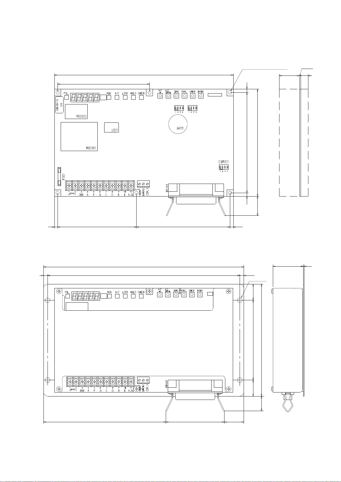
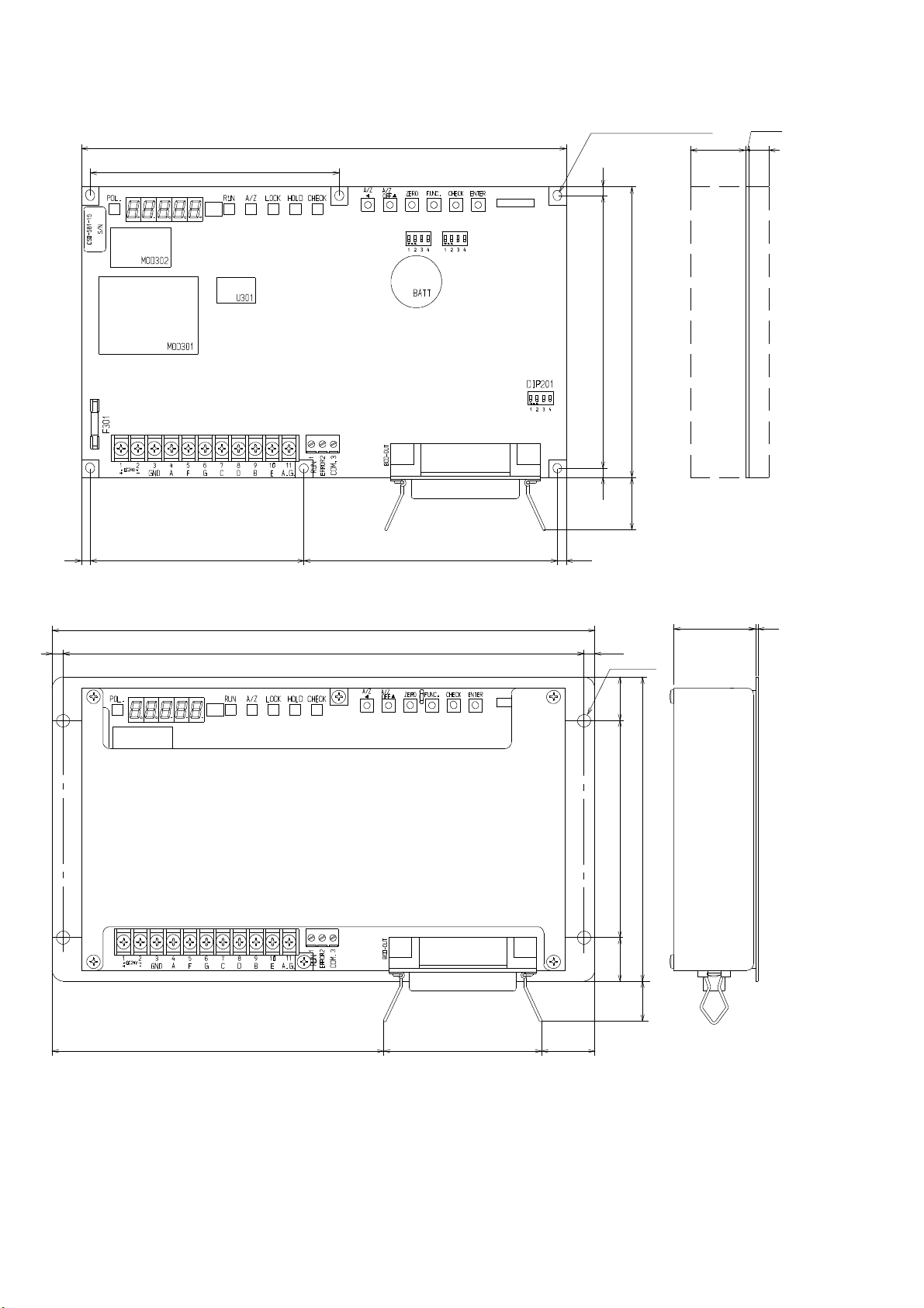
Each dimensions of the instrument and required dimensions for the environmental
spaces are as follows:
Dimensions for installation
113
220
DIP202
DIP203
CN202
6−φ4 land □6
4
122
130
25
Required space for application
1.6
9
Required space for application
4
(25)
4
97
115
4
Unit:mm
Dimensions when the optional metal cover(CSD581−P80) is installed.
250
5
240
(5)
4−φ6
20(20)
100
140
(37.6)
1
(152.5)
(19)
(73)
(24.5)
Unit:mm
V
Page 8

2. Power supply
Warning ●Be sure to check that power supply is off when installing each cable.
If the work is done with the power fed, there may have the possibility
of electric shock to the operator or even the possibility of destroying
the instrument.
● Before supplying the power, check that the indication of power supply
voltage/specifications for the instrument and the power going to
supply should be the same. If they are not equal, contact us.
If you use the instrument without checking them, it may
cause a damage in the instrument or electric shock to the operator.
● Grounding wire should be grounded securely. When grounding wire is
not connected, it may cause a malfunction of the instrument or
electric shock to the operator.
3. Application note
Warning ●Before using a new instrument or exchanging the strain gage applied
transducer for a new one, be sure to make calibration.
If calibration shall not be made, correct measured results may not be
obtained nor it may cause a malfunction in the instrument and there
may exist damage in peripheral equipments.
Besides, even though calibration had been made, there may occur the
similar case when the result is not correct, so make calibration again.
Warning ●In case of using the instrument, check that the connections are
executed properly. If not connected properly, correct measured result
will not be obtained, nor it may cause malfunctions of the
instrument, damage to the peripheral equipments or even worse
serious accidents.
Warning ●When change of setting is made carelessly on the instrument during
measurement, it may cause malfunction in the instrument and also
possibility of damage in peripheral equipments.
VI
Page 9

Warning ●Do not shock the instrument such as throwing something on it.
If neglected, it may cause destruction of the parts and damage to the
electrical circuits.
Warning ●Don’t push the key switch section on the instrument with
unnecessary strong force nor push it with sharp−edge object such as
driver. If neglected, it may cause a damage to the key switch and even
have the possibility of damage to operational performance.
Warning ●Don’t remove the parts of the instrument, nor take the instrument
into pieces. If neglected, it may cause a damage to the parts and even
have the possibility of damage to the electric circuits.
Warning ●There are a lot of electrical parts installed on the P.C. board of the
instrument, but take care not to touch them. If neglected, there may
cause electrostatics destruction.
Warning ●The P.C. board of the instrument have some sections that have high
temperatures around 50 ℃ or more in room temperature for a while
during supplying power or shutting off power supply (”MOD301”,
“U301”, “TR1, TR3 and radiator” indicated on the Fig. in the next
page.) , so care should be taken not to touch them. If neglected, it
may cause unexpected burns on your skin.
Warning ●The battery is installed on the P.C. board of the instrument, so care
should be taken not to short between the polarities of batteries
unnecessary. If neglected, there may cause remarkable deterioration
of the battery life, damage in the instrument or electric shock to the
operator.
VII
Page 10
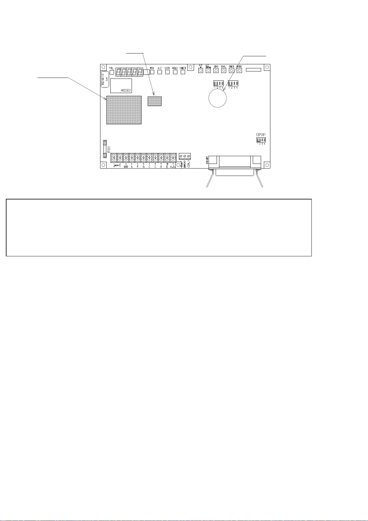
U301
Battery
MOD301
DIP202
DIP203
CN202
Warning ●Don’t supply the power when the instrument is placed directly on the
conductive material such as metal, and also when it is covered in
conductive bag for packaging. If neglected, it may cause the damage
in the instrument or electric shock to the operator.
VIII
Page 11

Conformity of CE standard
The instrument has conformed to the following standard.
EN61326−1:
EN50581:2012
The condition of the instrument to conform to this standard is as follows.
2013 “Electrical instruments for measurement, control, and
laboratory use−EMC request”
“Immunity test require ments for equipment intended for
use in industrial locations”
"Technical documentation for the assessment of electrical
and electronic products with respect to the restriction of
hazardous substances" (RoHS Directive)
Warning ●Please observe the following conditions strictly when the instrument
conforms to the above−mentioned standard. If neglected, there is a
possibility not to conform to the above−mentioned standard.
1. Storage case
The case to store the instrument must use the shielding case where EMC solution was
given. The main point of EMC solution of the case is shown below.
D Please exclude the insulating material such as “Painting”, and energize
electricity to all the contact sides such as the main body of the case, the case
cap, ducts, the instrument clamp, power supplies, and noise filters.
D “Packing” to bury “Space” of the main body of the case and the case cap
must use the one with energizing for EMC solution.
D Please exclude the insulating material such as “Painting”, and energize all
the contact sides of “Connector” and “Case” to “Connector” installed in the
case after using the one of “Metallic shell”.
D Please connect the main body of the case and the case cap with the electric
wire to keep energizing when the cap is opened.
D Please exclude an unnecessary opening as much as possible. Please give
some shield processing when you unavoidably install the opening.
D Please do not set up the deleterious noise source in the same case.
IX
Page 12
2. Connecting wires
(1). Shield processing
Please give certain shield processing by using “Shielded cable”, “Conduit piping”,
and “Shield wiring material besides” for connecting the I/O cables of the
instrument. The main point to shield is shown below.
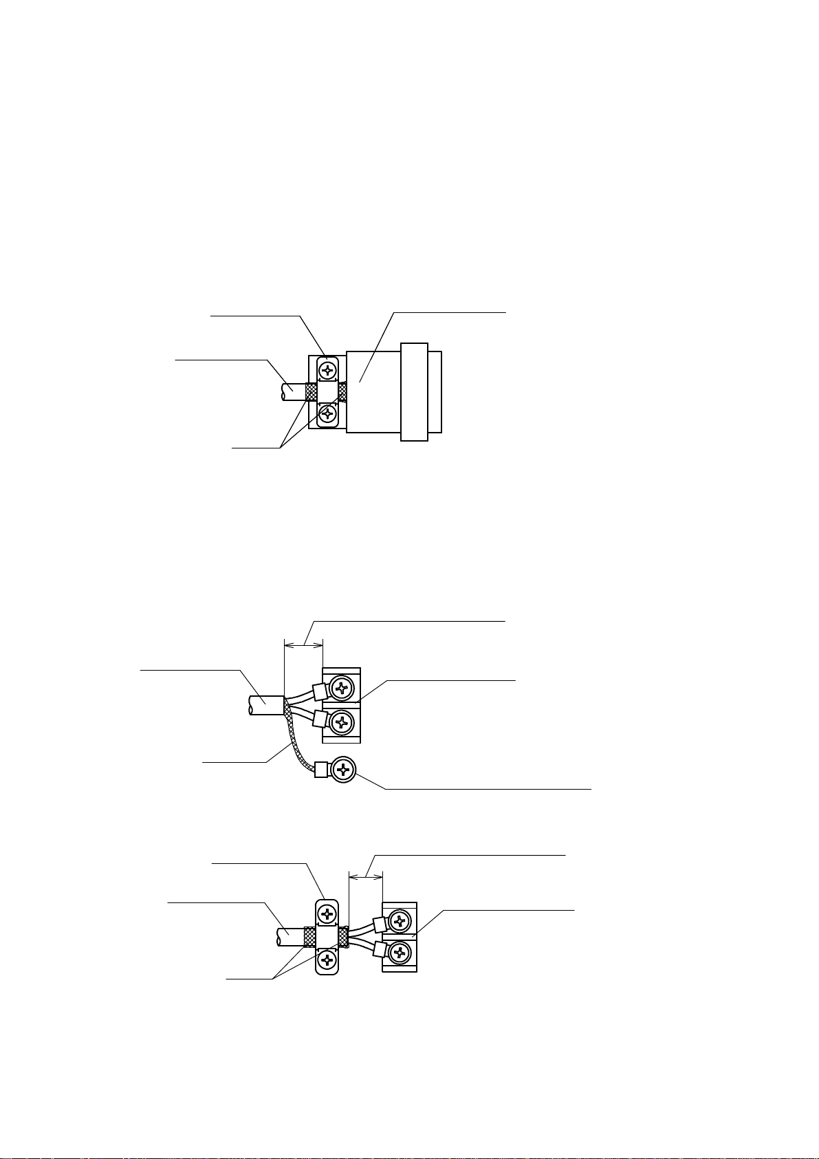
D When you use the shield connector plug of a shielded cable and a metallic
shell, the shield must be touched directly with the cable clamp section of
the connector as shown in the figure below.
Cable clump
Shielded cable
Shield
Connector plug
D When you install the connector receptacle and crimp−type terminal lugs in
the point of the shielded cable, the shield is left for the cable point as much
as possible, and connect the shield with the case as shown in the figure
below.
・When connecting directly with the case
Shortens as much as possible.
Shielded cable
Terminal block etc.
Shield
Connects directly with the case.
・When connecting with the case by the metal clamping
Cable clump
Shielded cable
Shield
Shortens as much as possible.
Terminal block etc.
X
Page 13
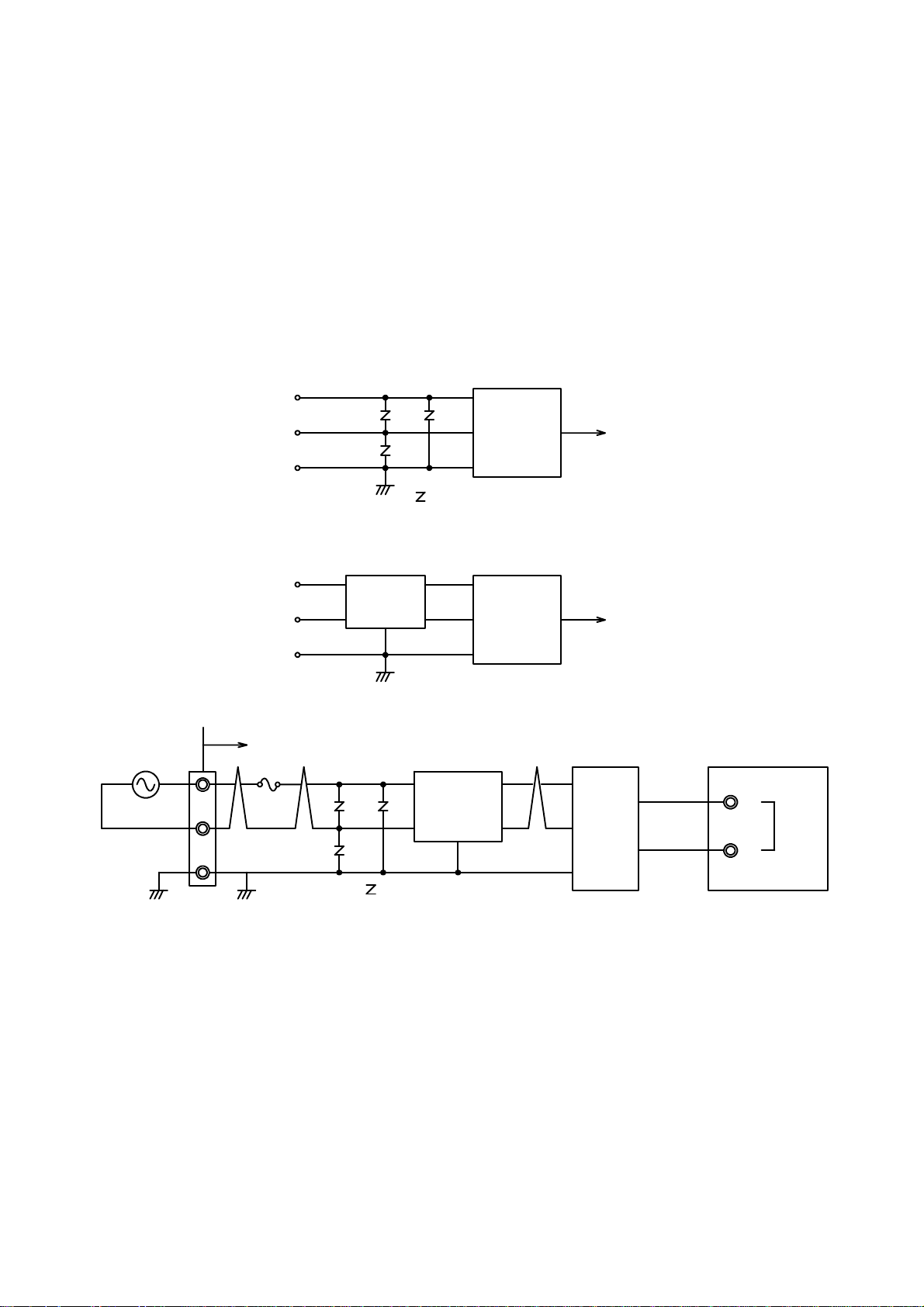
(2). Power supply
Please execute the following items for the power supply and wiring by which
DC24 V is supplied to the instrument.
D Please set up the DC24 V power supply used in the same storage case as the
instrument.
D The supplied DC24 V power supply must use “Conformed product of CE
standard”.
D Please install the serge solution element such as ”Varistor” which
correspond to the first side power supply voltage in the first side of the
DC24 V power supply.
AC
AC
F. G.
Power
supply
:Varistor
DC24 V
D Please install ”Noise filter” which corresponds to the first power supply
AC230 V 50 Hz
voltage in the first side of the DC24 V power supply if necessary.
AC
AC
F. G.
Noise
filter
Power
supply
DC24 V
The example of the power circuit section reference is shown below.
In storage case
FUSE
V1
V3
V2
:Varistor
Noise
filter
Power
supply
24 V
0V
CSD−581−15
1
+
2
−
V1 :Surge absorber/ERZV 9D 391 (Matsushita)
V2、V3 :Surge absorber/ERZV 10D 751 (Matsushita)
NF :Noise filter/ZHG 2203−11S (TDK)
DC24 V
PS :Switching power supply/JAW24−OR5C (TDK)
XI
Page 14

(3). Ground
Please execute the ground of the instrument surely according to the following
items.
D Please make the single ground of the instrument, or make the single
ground of the storage case after connecting the instrument with the storage
case when you store only the DC24 V power circuit for the instrument and
the instrument in the storage case.
D Please give the earth of the instrument as a single earth when you store
equipment other than the instrument in the storage case.
XII
Page 15

History of revision
Date Instruction manual No. Details of revised point
AUG, 1999 DRW. NO.EN294-1107
May. 2000 DRW. NO.EN294-1107-A
Nov. 2000 DRW. NO.EN294-1107-B
Mar. 2001 DRW. NO.EN294-1107-C
July, 2001 DRW. NO.EN294-1107-D
Sep. 2001 DRW. NO.EN294-1107-E
Dec. 2003 DRW. NO.EN294-1107-F
First version ROM Ver.1.000 or later
Due to ECN No. FN00−02060.
−Correction−
−The size in the Outline dimensions in P. Ⅴ, 6 and 96 is
changed.
Due to ECN NO.FN00−02109
- Additional -
Add the Details and conditions of comformance to CE
standard
Due to ECN No.FN01−02042
- Correction -
P.55 7−2−6 Output condition at Positive logic
Output data “Yes ”→Condition of transistor “OFF”
Output data “No”→Condition of transistor “ON”
Due to ECN No.FN01−02105
-Change-
Change the unit of power consumption from “VA” to “W”.
Due to ECN No.FN01−02134
-Changeー
Operating temperature range
“0 ℃ to 50 ℃”→ “-10 ℃ to 50 ℃”
Due to ECN No.FN03−02188
-Changeー
12−2. Screw size for attachment/removal of metal cover
“6−bind machine screw M3x6”→“6−bind machine screw
M3x10”
Due to ECN No.FN04−02111
Sep. 2004 DRW. NO.EN294-1107-G
Apr. 2005 DRW. NO.EN294-1107-H
June. 2009 DRW. NO.EN294-1107-I
Feb. 2010 DRW. NO.EN294-1107-J
Oct. 2010 DRW. NO.EN294-1107-K
-Changeー
7−13. “Back−up life will be about 10 years or more...” has
changed to “Back−up life will be about 10 years...”.
Due to ECN No.FN05−02035
− Addition −
At the warning column in the wiring section, the clause of ”As
there is a case which standard wiring color is different, please
confirm the inspection data sheet of the load cell being used.”
is added.
Due to ECN.FN09−02035
Changed CE conformity standard EN61326−1:2006
−Addition−
”Immunity test requirements for equipment intended for use
in industrial locations”
Due to ECN.FN10−02026
− Change −
Front cover’s logo is changed.
Due to ECN.FN10−02140
− Change −
Minebea logo is changed.
XIII
Page 16

Date
Instruction manual No.
Details of revised point
Due to ECN FN15-02132B
2. Each name and function
Jan.2018 DRW. NO.EN294 -1107-L
Mar.2018 DRW. NO.EN294 -1107-M
Due to ECN FN17-02017
・Delete the company name in the contents.
Due to FN17-02066E
Add and correct the applicable standard.
- Add [EN50581・2012]
- Correct from [EN61326-1:2006] to [EN61326-1:2013]
-Correct miswriting-
1. Installation place
・Dimensions for installation
・Dimensions when the optional metal cover(CSD581−P80)
is installed.
3. Application note
2. Each name and function
3−3. Installation
1E
4−3−1.○
4−3−1.
AConnection with strain gage applied transducers
2E
A○
Ai) In case of application of CAB−502 (4 cores cable)
ii) In case of application of CAB−501(6 cores cable)
3E
A○
4−3−1.
Ai) In case of application of CAB−502(4 cores cable)
ii) In case of application of CAB−501(6 cores cable)
4E
A○
4−3−1.
Ai) In case of application of CAB−502 (4 cores cable)
ii) In case of application of CAB−501(6 cores cable)
4−3−2. Connection with external control input
4−3−3. Connection with open collector output
4−3−4. Connection with power supply and ground
7−2−7. Selection of output logic for P.C.
(Print command), and its width
7−7. Change of bridge power supply voltage
10−11. Outline dimensions
12−1. Replacement of fuse
12−2. Attachment/removal of optional metal cover
(CSD581−P80)
- Additional-
XIV
Page 17

CONTENTS
FORWARD Ⅰ.......................................................
Marks and arrangement used in this manual Ⅱ.......................
For safe operation Ⅲ...............................................
1. Installation place Ⅲ.........................................................
2. Power supply Ⅵ.............................................................
3. Application note Ⅵ..........................................................
Conformity of CE standard Ⅸ....................................................
1. Storage case Ⅸ.............................................................
2. Connecting wires Ⅹ.........................................................
Record of revision ⅩⅢ.............................................................
1. General 1.................................................................
1−1. Features 1..........................................................
2. Each name and function 2.................................................
3. Installation procedures 4..................................................
3−1. Installation place 4....................................................
3−2. Location where installation is not allowed. 4.............................
3−3. Installation 5.........................................................
4. Connecting method 7......................................................
4−1. Layout of terminals and BCD output connector 7.........................
4−2. Note on connection 8..................................................
4−3. Connections 9.........................................................
4−3−1. Connection with strain gage applied transducers 9..................
4−3−2. Connection with external control input 17...........................
4−3−3. Connection with open collector output 18............................
4−3−4. Connection with power supply and ground 19........................
5. Calibration procedures 20...................................................
5−1. Preparations 20........................................................
5−2. Calibration procedures 20...............................................
−2−1. Calibration method to register the output of strain gage applied transducer at the time of
5
maximum display after setting the loa 21...........................................
5−2−2. Calibration method to register the output of strain gage applied transducer at the time of
zero and the maximum display 26.................................................
5−2−3. Calibration method to register by reading output value of strain gage applied transducer in
the conditions at zero and actual lo 31.............................................
5−2−4. Fine adjustment on zero 37........................................
5−2−5. Fine adjustment on span 39........................................
5−2−6. Calibration procedure to apply registration again for zero point only 41
5−3. Selection of calibration procedures on each condition 43....................
5−3−1. In case of executing the calibration on new instrument. 43............
5−3−2. In case of executing re−calibration 46...............................
6. Operating procedures 47....................................................
6−1. “A/ZA” key 47..........................................................
6−1−1. Operations in Measurement mode 47...............................
6−1−2. Operations in another modes 47....................................
6−2. “A/Z OFF Y” key 47....................................................
6−2−1. Operation in Measurement mode 47................................
Page 18

6−2−2. Operation in another modes 48.....................................
6−3. “ZERO” key 48.........................................................
6−3−1. Operation in the Measurement mode 48.............................
6−4. “FUNC.” key 48........................................................
6−4−1. Operation in the Measurement mode 48.............................
6−4−2. Operation in another modes 48.....................................
6−5. “CHECK” key 48.......................................................
6−5−1. Operation in the Measurement mode 48.............................
6−5−2. Operation in another modes 48.....................................
6−6. “ENTER” key 48.......................................................
7. Function and operation 49..................................................
7−1. External control input signal and open collector output signal 49............
7−1−1. External control input signal 49....................................
7−1−2. Open collector output signal 50.....................................
7−1−3. Equivalent circuit 50..............................................
7−2. BCD output 51.........................................................
7−2−1. Related function 51...............................................
7−2−2. Specifications for BCD output 51...................................
7−2−
3. BCD output connector pin configuration 52..........................
7−2−4. Equivalent circuit for input/output 53...............................
7−2−5. Timing chart 53..................................................
7−2−6. Output condition 55...............................................
7−2−7. Selection of output logic for P.C.(Print command), and its width 55....
7−3. How to use filter 57.....................................................
7−3−1. Digital filter 57...................................................
7−4. Zero tracking 58........................................................
7−4−1. What is zero tracking? 58..........................................
7−4−2. Setting related with zero tracking 58................................
7−4−3. Target of zero tracking 58..........................................
7−4−4. Cancellation for data compensation by Zero tracking 59...............
7−5. Stabilizing filter 60.....................................................
7−5−1. What is stabilizing filter? 60........................................
7−5−2. Setting related with stabilizing filter 60.............................
7−6. Various kinds of functions related with display 62..........................
7−6−1. Selection of target of display on load display 62.......................
7−6−2. Selection of target of HOLD 62.....................................
7−6
−3. Range of load display 62...........................................
7−7. Change of bridge power supply voltage 63.................................
7−8. Tare weight cancelation (A/Z) 64.........................................
7−9. Zero set 64.............................................................
7−10. Digital Tare weight cancellation 64.......................................
7−11. Key lock 65............................................................
7−12. CHECK value 65.......................................................
7−13. Memory position for setting data and so on 66.............................
7−14. Check mode 66.........................................................
7−14−1. Operating procedures for the Check mode 67.........................
7−15. Monitor mode 72.......................................................
8. Function mode 74..........................................................
8−1. Setting method for Function mode 74.....................................
8−2. Function on Function data 76............................................
Page 19

8−3. Target for BCD output 80...............................................
9. Trouble ・shooting 81......................................................
9−1. Executing trouble・shooting 82..........................................
9−2. Error display 91........................................................
10. Specifications 93...........................................................
10−1. Specifications for analog 93..............................................
10−2. Specifications for digital 93..............................................
10−3. Key SW function 93.....................................................
10−4. Output signal for open collector 93.......................................
10−5. BCD output 94.........................................................
10−6. Various kinds of functions 94............................................
10−7. General specifications 94................................................
10−8. Standard specifications at the shipment 95................................
10−9. Accessories 95..........................................................
10−10. Options 95.............................................................
10−10−1. Metal cover 95....................................................
10−11. Outline dimensions 96..................................................
11. Warranty 97................................................................
11−1. Warranty 97...........................................................
11−2. Repair 97..............................................................
12. Appendix 98...............................................................
12−1. Replacement of fuse 98..................................................
12−2. Attachment/removal of optional metal cover(CSD581−P80) 99
12−3. Character’s pattern for display 100........................................
..............
Page 20

Page 21

1. General
The instrument is a digital indicator for the application of strain gage applied transducers.
1−1. Features
Main features for CSD−581−15 are as follows :
(1) P.C. board type
Only one piece of P.C. board can perform the function of digital indicator with BCD output
applied, and it is suitable for the application inside of control panel.
(2) Automatic calibration function
By the registration for rated output data (X.XXXX mV/V) for strain gage applied transducer,
calibration can be performed automatically.
1
Page 22
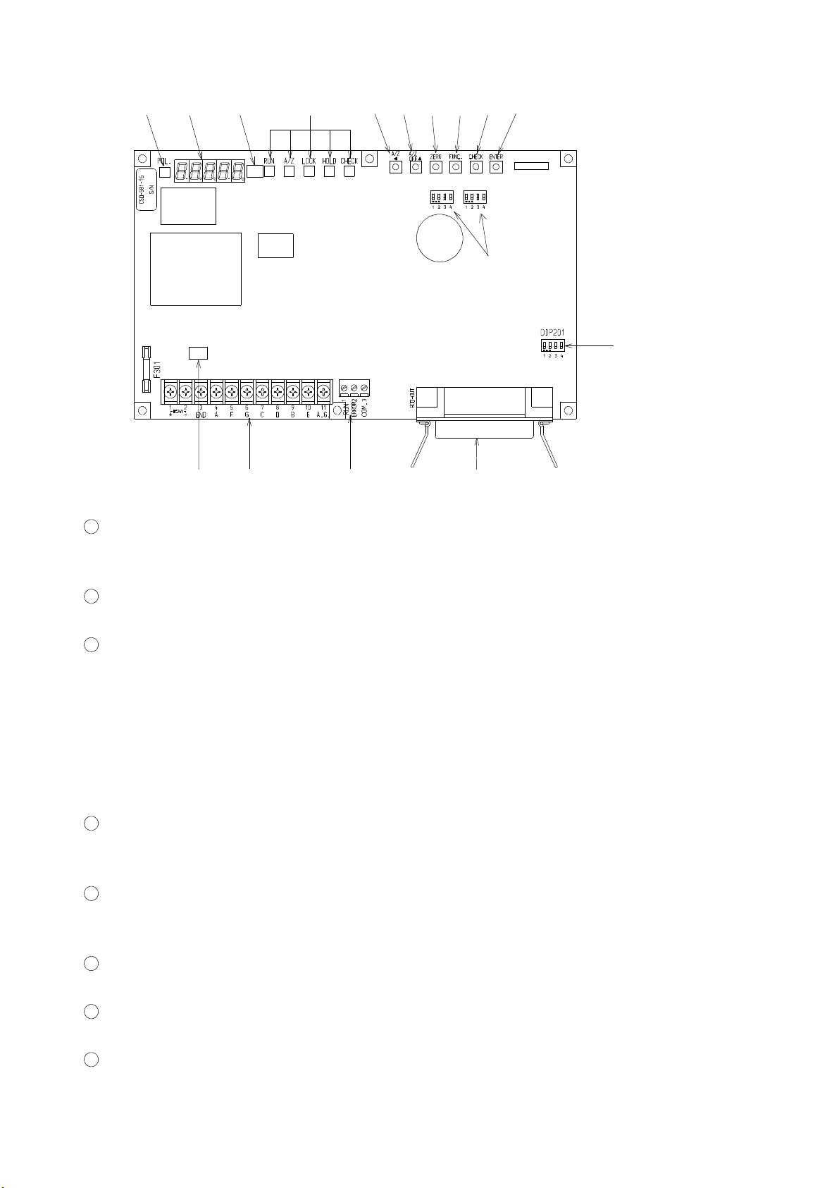
2. Each name and function
②
①
⑩
③
④⑤⑥⑦⑧⑨
DIP202
DIP203
⑯
⑭⑪ ⑫ ⑬
CN202
⑮
1
Load display
The load data is shown in Measurement mode, and status display will be shown in various
kinds of Calibration modes and Setting mode.
2
POL. (Polarity) display
Displays polarities for load data. Lights up when the load data is minus “−”.
3
Status display
RUN Lights up when the instrument is in the Measurement mode.
A/Z Lights up when Tare weight cancellation is performed(A/Z ON). And puts off when
Tare weight cancellation is cleared. (A/Z OFF)
LOCK Lights up when between the LOCK at external control input and COM. is shorted.
Key switch operation can’t be made during lighting up.
HOLD Lights up when between the HOLD at external control input and COM. is shorted.
CHECK Lights up when CHECK is ON with the “CHECK” key pressed.
4
“A/Z A ” key
Executes Tare weight cancellation (A/Z). Moreover, it is applied when carrying up various
kinds of setting values are required.
5
“A/Z OFF Y” key
Executes Tare weight cancellation clear(A/Z OFF). Moreover, it is applied for numerical
increment at the time of various kinds of setting.
6
“ZERO” key
Executes Zero set (One touched zero adjustment).
7
“FUNC.” key
Used for shifting to the Function mode.
8
“CHECK” key
2
Page 23

Used when ON/OFF operation of CHECK value is required.
9
“ENTER” key
Used for registering the set value at the time of various kinds of settings.
10
Position of pasting the Unit seal
As necessity requires, paste the Unit seal attached.
11
Terminals 1
Connects with various kinds of strain gage applied transducer such as load cell, ground earth
wire and DC power supply.
12
Terminals 2
Connects with “RUN” and “ERROR” for open collector output.
13
BCD output connector
Connects with BCD output, “ZERO”, “A/Z”, “A/Z OFF”, “HOLD”, “LOCK”, “SEL1” and
“SEL2” for external control input.
14
Bridge power supply voltage changeover switch
Used when the bridge power voltage is selected from “10 V” and “2.5 V ”.
15
DIP switch for P.C. output settings
Used for setting the P.C. output logic and the P.C. width at BCD output.
⑯ DIP switch for operation change when program is written
Use it at the time of the program rewriting.
Do not change the setting. When the setting is changed, it doesn't operate.
Only SW208-1 is turned on when the customer is used, and the other seven poles are turning off.
3
Page 24

3. Installation procedures
3−1. Installation place
● Use the instrument where the temperature/humidity specifies within
the range as follows:
Environmental temperature :−10 ℃ to 50 ℃
Environmental humidity :Less than 85 %R.H.(Non condensing.)
3−2. Location where installation is not allowed.
Warning ● Don’t locate the instrument on the places such as follows:
It may cause an unexpected faulty in the instrument.
D Don’t expose the instrument in direct sunlight and/or high temperature area.
D Don’t use the instrument in a high humid area.
D Don’t install the instrument where there is high mechanical vibration.
D Don’t use the instrument where there is an excess of dusts and fine particles.
D Don’t install the instrument where there include any corrosive gas or any salty
atmosphere.
D Don’t install the instrument where there is rapid change of temperature and humidity.
D Don’t install the instrument near the devices that are magnetized or generate an
electromagnetic field.
D Don’t install the instrument where there may suffer radioactivity or radioactive rays.
D Avoid the location where chemical reaction may take place such as in a laboratory.
4
Page 25
3−3. Installation
Warning ● There are a lot of electrical parts installed on the P.C. board of the
instrument, so there have fears to occur electrostatics destruction.
Because of this, operator should discharge electricity from him/her by
touching some conductive metal sections before use.
Besides, take care not to touch electrical parts when you operate.
● Please observe the condition shown in the paragraph of “Conformity
of CE standard in the FORWARD” strictly when conforming to
conformity of CE standard. There is a possibility not to conform to
the standard when these are neglected.
● When installing the instrument, install
dimensions and secure the space around the instrument.
● When installing the instrument, we recommend you to prepare for
the cover considering the following items.
Besides, we prepares fitting metal to cover the instrument as an
option.
1
There are a lot of ICs on the P.C. board of the instrument that may
be destroyed eternally due to static electricity, so in order to
prevent the human from touching them directly.
2
The battery is installed on the P.C. board of the instrument, so in
order to prevent from shorting between the polarities of battery
carelessly.
3
There are some places that have high temperature around 50 ℃ or
more in the room temperature, so in order to prevent the operator
from touching the areas carelessly.
as referring to the following
● The protection tape for the battery polarities is applied on the part of
battery(front side) and battery terminal(rear side) of this instrument.
● The bag for packaging used for the instrument is made from the
conductive material, so don’t use this bag with the protection tape for
each battery polarities removed.
5
Page 26
Each dimensions of the instrument and required dimensions for the environmental spaces are as
follows:
113
220
DIP202
DIP203
CN202
6−φ4 land □6
4
122
130
25
Required space for application
1.6
9
Required space for application
4
(25)
4
97
115
4
Unit:mm
Dimensions when the optional metal cover(Option:CSD581−P80) is installed
250
5
(152.5)
240
(73)
(24.5)
(5)
4−φ6
20(20)
100
140
(19)
(37.6)
Unit:mm
1
6
Page 27
4. Connecting method
m
T
transducer
l
m
4−1. Layout of terminals and BCD output connector
There are 2 pieces of terminals, one has 11 pieces of terminal points (Terminals 1)
and the other has 3 pieces of terminal points (Terminals 2) and also attached BCD output
connector.
Layout of terminals and BCD output connector are shown in the following figure.
D Terminals
Terminal NO. Name Applications
1 DC24 V(+)
2 DC24 V(−)
3 GND
4 A (Bridge power supply +)
ls 1
ina
er
5 F (Sensing +)
6 G (Sensing −)
7 C (Bridge power supply −)
8 D (Amplifier input +)
9 B (Amplifier input −)
10 E (Shield)
11 A.G.
l2
mina
Ter
1 RUN
2 ERROR
3 COM.
D BCD output connector
1
2 1×10
3 2×10
4 4×10
5 8×10
6 1×10
7 2×10
8 4×10
9 8×10
10 1×10
11 2×10
12 4×10
COM. 13 8×10
0
0
0
0
1
1
1
1
2
2
2
Power supply
Strain gage applied
Analog ground
Open collector output
14 1×10
15 2×10
16 4×10
17 8×10
18 1×10
2
3
3
3
3
4
25 ERROR
26 P.C.
27 HOLD
28 LOCK
29 SEL.1
30 SEL.2
19 COM. 31 ZERO
20 2×10
21 4×10
22 8×10
4
4
4
32 A/Z
33 A/Z OFF
34 N.C.
23 POL. 35 N.C.
24 OVR. 36 N.C.
● Don’t connect with the N.C. pin at the BCD output connector.
● The COM. on the terminals 2 and COM. on BCD output connector
are connected internally.
7
Page 28
4−2. Note on connection
Warning ● In case of connection with the instrument, keep strictly to the
following items. If neglected, it may cause an unexpected failure
or a damage to the instrument.
●Please observe the condition shown in the paragraph of “Conformity
of CE standard in the FORWARD” strictly when conforming to
conformity of CE standard. There is a possibility not to conform to
the standard when these are neglected.
D Be sure to set the power supply to OFF position, when connection is made.
D Since the terminals of the instrument is made of resin, take care not to drop it down
or not to apply strong impact.
D When you will use, be sure to apply the attached acrylic cover located on the terminals.
D Recommended torque to tighten the terminal screws for terminals should be as follows :
① Terminals 1:0.8 N・m at maximum
② Terminals 2:0.6 N・m at maximum
D The suitable crimp−type terminal lugs for the terminals 1 should be as follows:
Width of crimp−type terminal lugs
6.0 mm or less 1.25−3 or Y type 1.25−3.5
D Suitable ranges of wire for terminals 2 are as follows:
Stranded wire from 0.14 mm
D Suitable plug for BCD output connector is as follows:
57−30360 made by DDK.
D Connecting cable with the instrument should be away from the noise source such as power
supply line and I/O line for control and so on as far as possible.
D Conduit wiring should be the type of exclusive one, and avoid using with another line
together.
D Since the A.G. terminal (Terminals 1: Terminal number 11) is internal analog ground for
the purpose of maintenance, so don’t connect with externals.
D All of the connections should be executed securely according to the Instruction manual.
2
to 1.5 mm2(AWG26 to AWG16)
Suitable crimp−type terminal lugs
8
Page 29
4−3. Connections
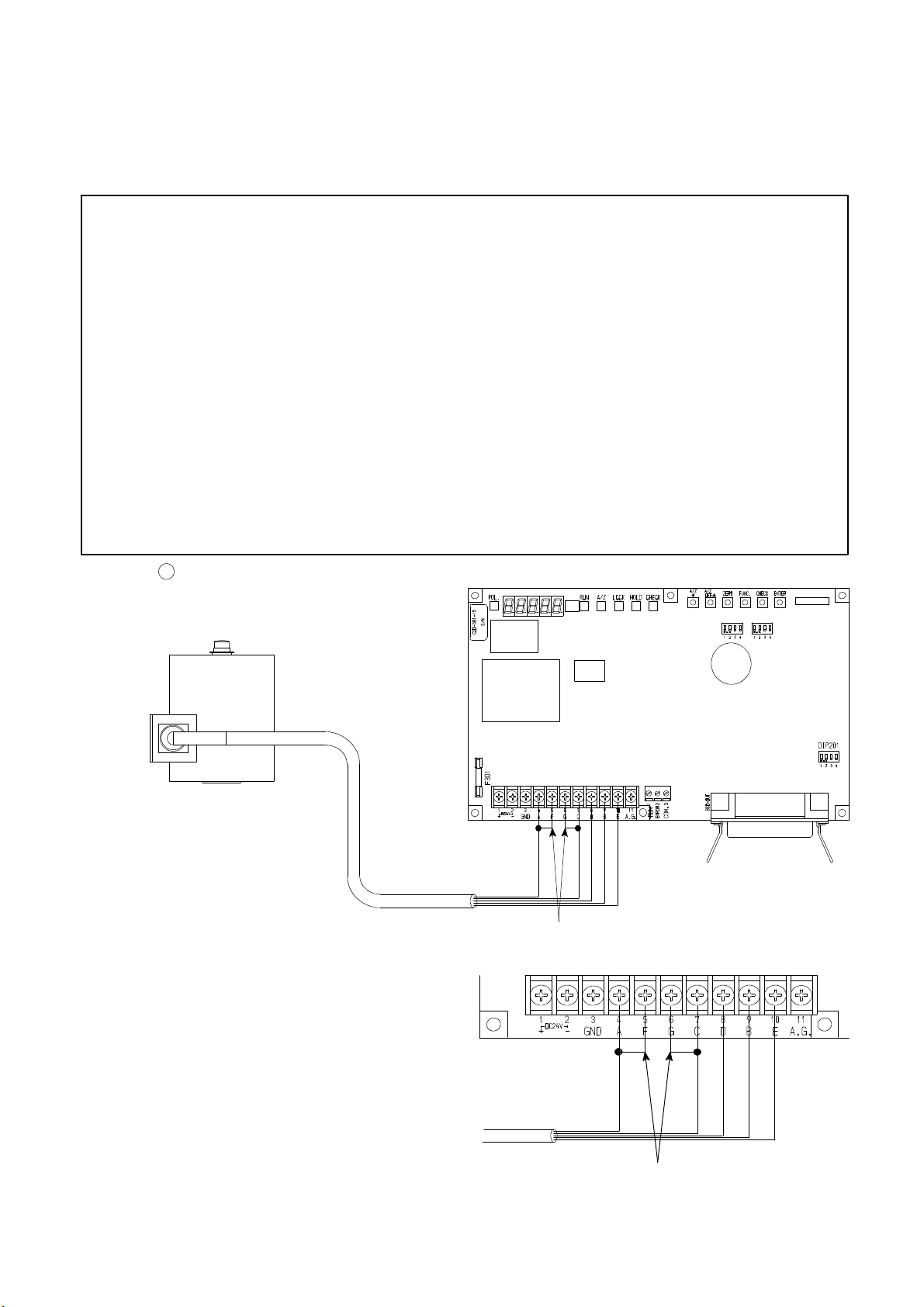
4−3−1. Connection with strain gage applied transducers
The instrument can connect with strain gage applied transducers, such as load cell, pressure
transducer and so on. Here, we will describe the example of connections with load cell, so
connect with another type of strain gage applied transducers in the same way.
※1 When tension is applied with the application of tension type or
universal(compression/tension) type of load cell, and display of “+”
direction is required, connect “Green” with Terminal No.9 at
terminals 1, and “blue” with Terminal No.8 at terminals 1
individually. As there is a case which standard wiring color is
different, please confirm the inspection data sheet of the load cell
being used.
※2 When the total length of CAB−502 specifies more than 30 m, the
accuracy may be out of warranty because the resistance of cable
makes the input voltage of the instrument decreased.
※3 When the total length of CAB−501 specifies more than 100 m, the
accuracy may be out of warranty, because the resistance of cable
makes the remote sensing function of the instrument deteriorated.
1
Connection with one set of Load cell and CSD−581−15
3m
Attached short bars
Enlarged figure for connecting section
RED
DIP202
DIP203
WHT
Shield
※1GRN
※1BLU
CN202
RED
Attached short bars
9
WHT
※1GRN
Shield
※1BLU
Page 30
※1 When tension is applied with the application of tension type or
universal(compression/tension) type of load cell, and display of “+”
direction is required, connect “Green” with Terminal No.9 at
terminals 1, and “Blue” with Terminal No.8 at terminals 1
individually. As there is a case which standard wiring color is
different, please confirm the inspection data sheet of the load cell
being used.
※2 When the total length of CAB−502 specifies more than 30 m, the
accuracy may be out of warranty because the resistance of cable
makes the input voltage of the instrument decreased .
※3 When the total length of CAB−501 specifies more than 100 m, the
accuracy may be out of warranty, because the resistance of cable
makes the remote sensing function of the instrument deteriorated.
2
Connection with one set of Load cell and Junction box for extension use B−304 and
CSD−581−15
i) In case of application of CAB−502 (4 cores cable)
Junction box
3m
※2 (Length of CAB−502 should be
within 30 m totally.)
B−304
CAB−502
DIP202
WHT
RED
Shield
※1BLU
※1GRN
Attached short bars
Enlarged figure for connecting section
DIP203
CN202
10
RED
WHT
Attached short bars
※1GRN
Shield
※1BLU
Page 31

B−304 Internal terminal connection
To Load cell
RED BLU
Terminal pitch 9.5 mm
BLU WHT GRN YEL(shield)
RED
ii) In case of application of CAB−501(6 cores cable)
Junction box
3m
B−304
WHT
GRN
YEL(shield)
Suitable crimp−type
terminal lugs:1.25−4or2−4
To CSD−581−15
DIP202
DIP203
CN202
CAB−501
※3 (Length of CAB−501 should be
within 100 m totally.)
B−304 Internal terminal connections
to Load cell
Terminal pitch 9.5 mm
ORN
WHT
ORN
RED
BLK
Shield
※1GRN
※1BLU
Enlarged figure for connecting section
ORN
RED
BLK
GRN
YEL(shield)
Suitable crimp−type
terminal lugs:1.25−4or2−4
YEL(shield)
GRN
WHT
to CSD−581−15
RED BLU WHT
BLU
RED
BLK
WHT
※1GRN
Shield
※1BLU
11
Page 32

※1 When tension is applied with the application of tension type or
universal(compression/tension) type of load cell, and display of “+”
direction is required, connect “Green” with Terminal No.9 at
terminals 1, and “Blue” with Terminal No.8 at terminals 1
individually. As there is a case which standard wiring color is
different, please confirm the inspection data sheet of the load cell
being used.
※2 When the total length of CAB−502 specifies more than 30 m, the
accuracy may be out of warranty because the resistance of cable
makes the input voltage of the instrument decreased.
※3 When the total length of CAB−501 specifies more than 100 m, the
accuracy may be out of warranty, because the resistance of cable
makes the remote sensing function of the instrument deteriorated.
3
Connection with 2 to 4 points of Load cells and Summing type Junction box with balance
adjustment applied (B−307) and Digital indicator CSD−581−15
i) In case of application of CAB−502(4 cores cable)
Junction box
B−307
※2 (Length of CAB−502 should be
30 m totally.)
CAB−502
DIP202
DIP203
WHT
RED
Attached short bars
Shield
※1GRN
※1BLU
Enlarged figure for connecting section
CN202
12
RED
Attached short bars
WHT
※1GRN
Shield
※1BLU
Page 33

B−307 Internal terminal connections
WHT
RED
GRN
BLU
YEL(shield)
WHT
RED
GRN
BLU
YEL(shield)
WHT
RED
GRN
BLU
YEL(shield)
WHT
RED
GRN
BLU
YEL(shield)
1W
1R
1G
1B
1Y
2W
2R
2G
2B
2Y
3W
3R
3G
3B
3Y
4W
4R
4G
4B
4Y
ii) In case of application of CAB−501(6 cores cable)
RD
OR
BK
WH
GN
BL
YE
RED
WHT
GRN
BLU
YEL(shield)
To
CSD−581−15
Junction box
B−307
CAB−501
※3 (Length of CAB−501 should be
100 m totally.)
DIP202
BLK
WHT
RED
ORN
Shield
※1GRN
※1BLU
Enlarged figure for connecting section
DIP203
CN202
13
RED
ORN
WHT
BLK
※1GRN
Shield
※1BLU
Page 34

B−307 Internal terminal connections
WHT
RED
GRN
BLU
YEL(shield)
WHT
RED
GRN
BLU
YEL(shield)
WHT
RED
GRN
BLU
YEL(shield)
WHT
RED
GRN
BLU
YEL(shield)
1W
1R
1G
1B
1Y
2W
2R
2G
2B
2Y
4W
4R
4G
4B
4Y
3W
3R
3G
3B
3Y
RD
OR
BK
WH
GN
BL
YE
RED
ORN
BLK
WHT
GRN
BLU
YEL(Shield)
to CSD−581−15
14
Page 35

※1 When tension is applied with the application of tension type or
universal(compression/tension) type of load cell, and display of “+”
direction is required, connect “Green” with Terminal No.9 at
terminals 1, and “Blue” with Terminal No.8 at terminals 1
individually. As there is a case which standard wiring color is
different, please confirm the inspection data sheet of the load cell
being used.
※2 When the total length of CAB−502 specifies more than 30 m, the
accuracy may be out of warranty because the resistance of cable
makes the input voltage of the instrument decreased.
※3 When the total length of CAB−501 specifies more than 100 m, the
accuracy may be out of warranty, because the resistance of cable
makes the remote sensing function of the instrument deteriorated.
4
Connection with 2〜4 points of Load cells and Summing type Junction box (SB−310), and
CSD−581−15
i) In case of application of CAB−502 (4 cores cable)
※2 (Length of CAB−502 should be
within 30 m totally.)
SB−310
CAB−502
DIP202
WHT
RED
Attached short bars
Shield
※1GRN
※1BLU
Enlarged figure for connecting section
DIP203
CN202
15
RED
WHT
※1GRN
Attached short bars
Shield
※1BLU
Page 36

SB−310 Internal terminal connections
Output Port
To CSD−581−15
RD
RD
Short bars
Input port No. 1
WHGN BLYE
WH
GN
BL
Input Port
No. 4
Suitable crimp−type
terminal lugs
B
YE
A
・Y type
ii) In case of application of CAB−501(6 cores cable)
SB−310
RD
RD
RD
or
WH
WH
GN
WHGN
φB
BL
YE
YE
BL
YE
BLGN
φA
Input port No. 2
Input port No. 3
A:3.2 mm or less
B:7 mm or less
・Round type
DIP202
DIP203
CN202
CAB−501
※3 (Length of CAB−501 should be
within 100 m totally.)
WHT
BLK
RED
ORN
Shield
※1GRN
※1BLU
Enlarged figure for connecting section
RED
ORN
WHT
BLK
※1GRN
Shield
※1BLU
16
Page 37

Internal terminal connections for SB−310
Output
Port
RD
To CSD−581−15
RD
OR
BK
WH
GN
Input Port
No.4
BL
YE
Short bars
Input port No.1
RD
WHGN BLYE
RD
RD
RD
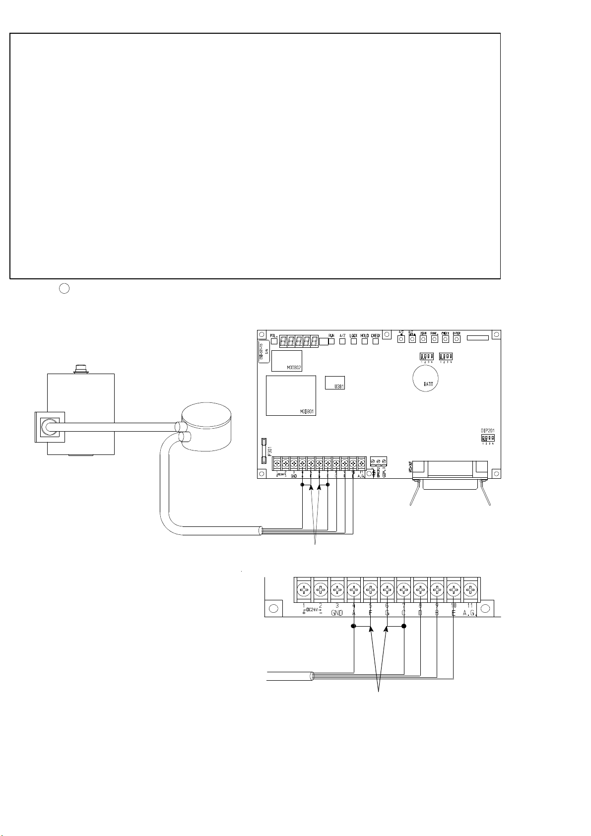
BL
YE
GN
WH
WH
YE
GN
BL
YE
BLGN
WH
Input port No.2
Input port No.3
Suitable crimp−type
terminal lugs
A
B
・Y type
4−3−2. Connection with external control input
Connection with external control input of “ZERO”, “A/Z”, “A/Z OFF”, “HOLD” , “LOCK”
“SEL 1” and “SEL 2” should be made by using contact or open collector as the below figure
indicates. Refer to the paragraph 7−1. External control input signal, open collector output
signal for each input functions.
DIP202
DIP203
CN202
or
φA
φB
A:3.2 mm or less
B:7 mm or less
・Round type
10
・
・
・
・
・
・
27
28
29
30
31
32
33
1.19
36
Connector
plug
57−30360
Shield
To connector plug case
or
Warning ● Connections with external control input should be made securely as
indicating in the above figure. If neglected, it may cause an
unexpected malfunction to the instrument.
● For the connection with external control input, be sure to apply
shielded cable, and shielded cable should be connected with the
connector plug case. If not connected, it may cause malfunction due
to the effect from external noises and so on.
17
Page 38

4−3−3. Connection with open collector output
Connection with open collector output “RUN” ,“ERROR” and external load should be made as
the following figure.
At the same time, care should be taken fully, so that the load doesn’t exceed the rated open
collector.
Rated open collector V
= DC30 V, IC= DC30 mA MAX.
CE
Enlarged figure for
connecting section
Shield
DIP202
DIP203
−
+
CN202
Load
Shield
−
+
Warning ● Connection with open collector output should be made securely
according to the figures and also use within the rated of open
collector. If neglected, it may cause an unexpected malfunction to the
instrument.
● For the connection with open collector output, be sure to apply
shielded cable, and the shielded cable should be connected with GND
terminal of the instrument.(Terminals 1:Terminal No.3).
If not connected, it may cause malfunction due to the effects from
external noises and so on.
18
Page 39

4−3−4. Connection with power supply and ground
Connection with power supply and ground should be made as follows:
Besides, grounding should be the D class with single ground.
Power supply voltage DC24 V (DC18 V to DC36 V)
Power consumption Approx. 9 W at maximum (At DC24 V)
DC24 V
(DC18 V to 36 V)
Enlarged figure for
connecting section
D class single ground
DIP202
DIP203
CN202
DC24 V
(DC18 V to 36 V)
D class single ground
Warning ● Connection with power supply and ground should be made securely
as the figure indicates, and also should be made within the specified
condition of power supply. If neglected, it may cause an unexpected
failure.
● Grounding for the instrument should be the D class with single
ground. If neglected, it may cause an unexpected malfunction due to
the effects of noise from another equipments.
● GND terminal (Terminals 1 : Terminal No.3) and land (F.G.) at the
installation hole for P.C. board of the instrument have connected on
the pattern of P.C. board .
19
Page 40

5. Calibration procedures
Warning ● Before using the new instrument or after exchanging the strain gage
applied transducer with a new one, be sure to make calibration.
If calibration is not made, correct measured results may not be
obtained, or it may cause malfunction to the instrument and it may
damage the peripheral equipment.
Moreover, even if calibration has made, there may occur the similar
case as above when the result is not correct. So make precise
calibration again.
5−1. Preparations
According to the section 4. Connecting method, connect the instrument and strain gage applied
transducer properly and supply the power.
5−2. Calibration procedures
There are 6 kinds of load calibration procedures for the instrument as follows:
1
Calibration method (Automatic calibration only for Span) to register the output (conversion
with mV/V) of strain gage applied transducer at the time of maximum display (weighing value)
after setting the load to zero (Initial load condition with tare weight).
2
Calibration method (Automatic calibration for Zero and Span) to register the output of strain
gage applied transducer (conversion with mV/V) at the time of zero(Initial load application
with tare) at the optional load condition, and also to register the output (conversion with
mV/V) of strain gage applied transducer at the time of maximum display (weighing capacity).
3
Calibration method (Actual load calibration) to register by reading output of strain gage
applied transducer, when setting in the condition of zero load (Initial load application with
tare) and in the condition of actual load applied individually.
4
Fine adjustment on Zero
5
Fine adjustment on Span
6
Calibration procedures to apply registration again for zero point only(Tare weight
cancellation).
● The accuracy of calibration obtained from ① and ② is 1/1 000 or so.
In the following paragraphs, we will describe each calibration procedure by showing the examples
with load cell applied.
20
Page 41

5−2−1. Calibration method to register the output of strain gage applied transducer at the time
of maximum display after setting the load to zero.
Warning ● Before using a new instrument or exchanging the strain gage applied
transducer for a new one, be sure to make calibration.
If calibration shall not be made, correct measured results may not be
obtained nor may cause malfunction in the instrument and there
may exist damage in peripheral equipments.
Besides, even though calibration had been made, there may occur the
similar case when the result is not correct, so make calibration again.
● During the calibration is executing, be sure to set Tare weight
cancellation clear, and to make cancellation (Execution of F−98) for
compensated data on zero set and also set the OFF position of Zero
tracking (Setting “00000” on F−07 and F−08 each.) If neglected,
correct measured results may not be obtained.
● During calibration procedures, press the “FUNC.” key in case of
interrupting the calibration is required. The calibration data will be kept as
they are before entering the calibration and then returns to the
Measurement mode.
● When the “A/Z A ” key is pressed with the load display of “FUNC.”,
the display will change as the following sequence at every time the
key is pressed. “FUNC”→“CCAL”→“ACA L ”→“LCAL”→“ZERO”→
“SPAN”→“TARE”→“CHECK”→“MONIT”→“F−END”→“FUNC”→
“CCAL”→・・・・・(Hereinafter, it will repeat.)
Procedures
Press the “FUNC.” key for approx. one second.
The load display will show “FUNC”.
1
21
Page 42

Procedures
Press the “A/Z A ” key once.
The load display will show “CCAL”.
2
Press the “ENTER” key. “CCAL” mode can be
entered, then the load display will show “D−01”
and it will light on and off.
When the calibration has completed already, the
set value of minimum scale which has registered
at that time will be displayed.
3
Set the minimum scale with “A/Z OFF Y” keys.
Setting value for the minimum scale will be 4
(four) as follows:
1, 2, 5, 10
“A/Z OFF Y” key :Set value increment key
Press the “ENTER” key.
The load display will show “DISP”.
4
22
Page 43

Procedures
Press the “ENTER” key.
The load display will show “2000”, and the digit
of minimum display will lights on and off.
When the calibration has completed already, the
registered value of maximum display at that time
will be displayed.
By the setting of minimum scale, the digit
of minimum display that lights on and off
will be as follows:
The minimum scale 1,2,5 10
The minimum scale 10 10
0
1
digit
digit
“A/Z A” key :Set value carry key
Set the maximum display value with “A/Z A”,
“A/Z OFF Y” and “CHECK” keys. Setting range
for the maximum display value will be (the
minimum scale×100)〜99 990.
5
In order to make effective use of the performance,
set within the following ranges.
When setting is made over the range as below,
there may occur unstable display and so on.
Setting range for max.
display value
100〜10 000
200〜20 000
500〜50 000
1 000〜99 990
Minimum scale
10
By pressing the key continuously, increment
can be provided continuously.
Press the “ENTER” key.
The load display will show “S MV”.
“A/Z OFF Y” key :Set value Increment key
“CHECK” key :Set value Initialization key
1
2
5
6
23
Page 44

Procedures
Press the “ENTER” key”.
The load display will show “0.3000”, and the
digit of 10
In case that calibration has completed already,
the registered output value of load cell at that
time will be displayed.
Set the output value for load cell corresponding
to the maximum display value that has set in
step 5 with “A/Z A”, “A/Z OFF Y” and
“CHECK” keys.
0
will flash on and off.
Though the number of digits has not
prepared in the “Inspection data” for load
cell so many as shown in the right figure,
7
extra digits are necessary for the
compensation with the standard point at
internal of the instrument.
In case of actual setting, insert “0”, into the
extra digits.
As for the value for extra digit, when tare
compensation and fine adjustment on load
are applied, it will be rewritten as a
compensated value automatically.
Setting range for the output of load cell is
from 0.200 0 mV/V to 3.100 0 mV/V.
By pressing the key continuously,
increment can be provided continuously.
Press the “ENTER” key.
The load display will show “ZERO”.
Here, set the instrument with initial load
application.
8
“A/Z A ” key :Set value carry key
“A/Z OFF Y” key :Set value Increment key
“CHECK” key :Set value Initialization key
24
Page 45

Procedures
Press the “ENTER” key.
The load display will show “−−−−−” with
lighting display on and off, then zero adjustment
can be started.
Warning :At the same time, take care
not to apply load vibration due to
vibration and so on. When load vibration
is applied, there will be possibilities that
zero point is unstable, and precise
9
reading of zero will not be obtained.
After completed, the load display will become
“T−END”.
However, when the initial load is not entered
within the range from −0.1 mV/V to 2.4 mV/V,
the error code shown in the right figure will
show for about 2 s, then load display will show
“ZERO” and return to step 8.
TER−L :Zero point − over
TER−H :Zero point + over
Press the “ENTER” key.
After “CCAL” mode is over, the load display will
show the present load.
10
Error code
Error code
25
Page 46

5−2−2. Calibration method to register the output of strain gage applied transducer at the time
of zero and the maximum display
Warning ● Before using a new instrument or exchanging the strain gage applied
transducer for a new one, be sure to make calibration.
If calibration shall not be made, correct measured results may not be
obtained nor may cause malfunction in the instrument and there
may exist damage in peripheral equipments.
Besides, even though calibration had been made, there may occur the
similar case when the result is not correct, so make precise calibration
again.
● During the calibration is executing, be sure to set Tare weight
cancellation clear, and to make cancellation (Execution of F−98) for
compensated data on zero set and also set the OFF position of Zero
tracking(Setting “00000” on F−07 and F−08 each).
If neglected, correct measured results may not be obtained.
● During calibration procedures, press the “FUNC.” key to interrupt
the calibration. It will hold the calibration data before interrupting
and will return to the Measurement mode.
● When the “A/Z A ” key is pressed with the load display of “FUNC.”,
the display will change as the following sequence at every time the
key is pressed. “FUNC”→“CCAL”→“ACA L ”→“LCAL”→“ZERO”→
“SPAN”→“TARE”→“CHECK”→“MONIT”→“F−END”→“FUNC”→
“CCAL”→・・・・・(Hereinafter, it will repeat.)
26
Page 47

Procedures
Press the “FUNC.” key for about one second.
The load display will show “FUNC”.
1
Press the “A/Z A ” key twice.
It will make the load display proceed as “FUNC”
→“CCAL”→“A C A L ” .
2
Press the “ENTER” key.
The ACAL mode can be entered, then the load
display will show “D−01” and lights on and off.
When the calibration has been already
completed, the registered set value of minimum
scale will be displayed.
3
Set the minimum scale with “A/Z OFF Y” key.
Set values for the minimum scale are 4(four)
kinds showing as follows:
1, 2, 5, 10
Press the “ENTER” key.
The load display will show “DISP”.
4
“A/Z OFF Y” key :Set value Increment key.
27
Page 48

Procedures
Press the“ENTER” key.
The load display will become “2000”, and the
digit of minimum display will light on and off.
When the calibration has been already completed,
maximum display value registered at that time
will be displayed.
By the setting of minimum scale, the digit
of minimum display that lights on and off
will be as follows:
The minimum scale 1,2,5 10
The minimum scale 10 10
Set the maximum display value with “A/Z A ”,
“A/Z OFF Y” or “CHECK” keys.
Setting range for the maximum display value will
5
be (the minimum scale×100)〜99 990.
In order to make effective use of the performance,
set within the following ranges.
0
digit
1
digits
“A/Z A ” key :Set value carry key
“A/Z OFF Y” key :Set value Increment key
“CHECK” key :Set value Initialization key
Setting range for max.
display value
100〜10 000
200〜20 000
500〜50 000
1 000〜99 990
By pressing the key continuously,
increment can be provided continuously.
Press the “ENTER” key.
The load display will show “Z MV”.
6
Minimum scale
1
2
5
10
28
Page 49

Procedures
Press the “ENTER” key.
The load display will become “0.0000”, and the
0
digit will light on and off.
10
When the calibration has been already
completed, the output value of load cell
registered at that time will be displayed.
Set the output value of load cell with the initial
load application by using “A/Z A ”, “A/Z OFF Y”
or “CHECK” keys.
Though the number of digits has not
prepared in the “Inspection data” for load
cell so many as shown in the right figure,
extra digits are necessary for the
7
compensation with the standard point at
internal of the instrument.
In case of actual setting, insert “0” into the
extra digits.
As for the value for extra digit, when tare
compensation and fine adjustment on load
are applied, it will be written as a
compensated value automatically.
Setting range for the output of load cell is
from −0.100 0 mV/V to 2.400 0 mV/V with
initial load applied.
By pressing the key continuously,
increment can be provided continuously.
Press the “ENTER” key.
The load display will show “S MV”.
“A/Z A ” key :Set value carry key
“A/Z OFF Y” key :Set value Increment key
“CHECK” key :Set value Initialization key
8
29
Page 50

Procedures
Press the “ENTER” key.
The load display will become “3.0000”, and the
digit of 10
When calibration has been already completed,
the output value of load cell registered at that
time will be shown.
Set the output value for load cell corresponding
to the maximum display value set in step 5 with
the “A/Z A”, “A/Z OFF Y” or “CHECK” key
0
will light on and off.
The setting value to be set here should be
at 0.2 mV/V or more than the set value in
the step 7.
Though the number of digits has not
9
prepared in the “Inspection data” for load
cell as many as the digits in the right
figure, extra digits are necessary for the
compensation for the internal standard
point of the instrument.
In case of actual setting, insert “0” into
the extra digits.
As for the value of extra digit, when tare
compensation and fine adjustment on load
are applied, it will be written as a
compensated value automatically.
By pressing the key continuously,
increment can be provided continuously.
Press the “ENTER” key.
The load display will show “T−END”.
“A/Z A ” key :Set value carry key
“A/Z OFF Y” key :Set value Increment key
“CHECK” key :Set value Initialization key
10
11
Press the “ENTER” key.
Quitting from the “ACAL” mode, the present load
value will show on the load display.
30
Page 51

5−2−3. Calibration method to register by reading output value of strain gage applied transducer in the
conditions at zero and actual load applied individually.
Warning ● Before using a new instrument or exchanging the strain gage applied
transducer for a new one, be sure to make calibration.
If calibration shall not be made, correct measured results may not be
obtained nor may cause malfunction in the instrument and there
may exist damage in peripheral equipments.
Besides, even though calibration had been made, there may occur the
similar case when the result is not correct, so make calibration again.
● During the calibration is executing, be sure to set Tare weight
cancellation clear, and to make cancellation (Execution of F−98) for
compensated data on zero set and also set the OFF position of Zero
tracking(Setting “00000” on F−07 and F−08 each.).
If neglected, correct measured results may not be obtained.
● During calibration procedures, press the “FUNC.” key to interrupt
the calibration. It will hold the calibration data before interrupting
and will return to the Measurement mode.
● When the “A/Z A ” key is pressed with the load display of “FUNC.”,
the display will change as the following sequence at every time the
key is pressed. “FUNC”→“CCAL”→“ACA L ”→“LCAL”→“ZERO”→
“SPAN”→“TARE”→“CHECK”→“MONIT”→“F−END”→“FUNC”→
“CCAL”→・・・・・(Hereinafter, it will repeat.)
31
Page 52

Procedures
Press the “FUNC.” key for about one second.
The load display will show “FUNC”.
1
Press the “A/Z A ” key three times.
It will make the load display proceed as “FUNC”
→“CCAL”→“A C A L ”→“LCAL”.
2
Press the “ENTER” key.
“LCAL” mode can be entered, and the load
display shows “D−01” and lights on and off.
When the calibration has been already
completed, the set value of minimum scale
registered at that time will be displayed.
3
Set the minimum scale with “A/Z OFF Y” key.
Set values for the minimum scale are 4 (four)
kinds as follows:
1, 2, 5, 10
Press the “ENTER” key.
The load display will show “DISP”.
4
“A/Z OFF Y” key :Set value Increment key
32
Page 53

Procedures
Press the”ENTER” key.
The load display will show “2000”, and the digit
of minimum display will lights on and off.
When the calibration has been already completed,
that maximum display value registered at that
time will be displayed.
By the setting of minimum scale, the digit
of minimum display that lights on and off
will be as follows:
The minimum scale 1,2,5 10
The minimum scale 10 10
Set the maximum display value with “A/Z A”,
“A/Z OFF Y” or “CHECK” keys.
Setting range for the maximum display value will
5
be (the minimum scale×100)〜99 990.
In order to make effective use of the
performance, set within the following ranges.
0
digit
1
digit
“A/Z A ” key :Set value carry key
“A/Z OFF Y” key :Set value Increment key
“CHECK” key :Set value Initialization key
Setting range for max.
display value
100〜10 000
200〜20 000
500〜50 000
1 000〜99 990
By pressing the key continuously,
increment can be provided continuously.
Press the “ENTER” key.
The load display will show “LOAD”.
6
Minimum scale
1
2
5
10
33
Page 54

Procedures
yg,
g
e
Press the “ENTER” key.
The load display will show “2000”, and the digit
0
will light on and off.
of 10
When the calibration has been already completed,
the output value of load cell registered at that
time applied actual load will be displayed.
By the setting of minimum scale, the digit
of minimum display that lights on and off
will be as follows:
The minimum scale 1,2,5 100digit
The minimum scale 10 10
7
Set the load value which is applied actually on
the load cell with the right keys.
The load value applied on the load cell should
be less than th
step 5, and at the same time within the range
of (the minimum scale ×100)〜99 990 which
can be applied on the load cell as the
maximum load value.
maximum display value setin
By pressing the key continuously,
increment can be provided continuously.
1
digit
”A/Z A ” key :Set value carry key
“A/Z OFF Y ” key :Set value Increment key
“CHECK” key :Set value Initialization key
Press the “ENTER” key.
The load display will show “ZERO”.
Now, set the initial load application.
8
34
Page 55

Procedures
Press the “ENTER” key.
The load display will become “−−−−−” with
flashing display on and off, then zero adjustment
can be started.
Warning :At the same time, be careful
not to apply load vibration due to
vibration and so on.
When load vibration is applied, it may
9
have the possibilities that zero point
becomes unstable, and precise reading of
zero will not be obtained.
After completing above, the indication on load
display will become “SPAN”.
However, when the initial load is not entered
within the range from −0.1 mV/V to 2.4 mV/V,
the error code shown on the right figure will be
displayed for about 2 s, and the load display will
show “ZERO”, then will return to step 8.
TER−L :Zero point − over
TER−H :Zero point + over
Apply thesame weight on theload cell as setin
10
the step 7.
Error code
Error code
35
Page 56

Procedures
figure
will
display
for
about
2
s,and
afterwards
Press the “ENTER” key.
The load display will show “−−−−−” with
lighting on and off, and Span adjustment will be
started.
Warning :At the same time, be careful
not to apply load vibration due to vibration
and so on.
11
When load vibration is applied, it may have
the possibilities that span will become
unstable, and precise reading of span will
not be obtained.
After completing above, the load display will
become “T−END”.
However, when the load corresponding to the
maximum display value is out of the range from
0.2 mV/V to 3.1 mV/V, the error code in the right
load display will be “SPAN”, then will returns to
step 9.
SPN−L :Span point − over
SPN−H :Span point + over
Press the “ENTER” key.
Quitting from the “ACAL” mode, the present load
value will show on the load display.
12
Error code
Error code
36
Page 57

5−2−4. Fine adjustment on zero
● During tare weight cancellation (A/Z) and zero set is executed, and
also during zero tracking is effective, zero fine adjustment mode can’t
be entered.(Displays ERR−5.) After executing tare weight
cancellation clear (A/Z OFF) and cancellation for compensated data
for zero set (Executes F−98.) and setting OFF the zero tracking
(F−07 & F−08 to show “0000”), enter in zero adjustment mode.
● When interrupting the calibration is required, press the “FUNC.” key
during the calibration procedures. The calibration data keeps the
same condition as it is entered before, then Measurement mode can
be entered.
● When the “A/Z A ” key is pressed with the load display of “FUNC.”,
the display will change as the following sequence at every time the
key is pressed. “FUNC”→“CCAL”→“ACA L ”→“LCAL”→“ZERO”→
“SPAN”→“TARE”→“CHECK”→“MONIT”→“F−END”→“FUNC”→
“CCAL”→・・・・・(Hereinafter, it will repeat.)
Procedures
Press the “FUNC.” key for about one second.
The load display will show “FUNC”.
1
Press the “A/Z A” key 4 times.
It will change the display of the load display as
“CCAL”→“A C A L ”→“LCAL”→“ZERO”.
At the same time, set the initial load condition.
2
37
Page 58

Procedures
5
Press the “ENTER” key.
Zero fine adjustment mode can be entered, then
display of load will show the present load value
and light on and off. At the same time, set the
present load value to “0” with “A/Z A” key or
“A/Z OFF Y” key.
By pressing the key continuously,
3
increment can be provided continuously.
The variation of load value for one push of
“A/Z A” or “A/Z OFF Y” key is less than
1 digit of display.
Therefore, a few pushes of those keys are
required to get the 1 digit of display value.
Press the “ENTER” key.
The indication of load display will show
“T−END”.
4
Press the “ENTER” key.
After quitting from zero fine adjustment mode,
the load display will show the present load.
“A/Z A” :Zero fine adjustment
Display Decrement key
“A/Z OFF Y” :Zero fine adjustment
Display Increment key
38
Page 59

5−2−5. Fine adjustment on span
● During Tare weight cancellation (A/Z) and zero set is executed, and
also during zero tracking is effective, span fine mode can’t be entered
(Displays ERR−5). After executing tare weight cancellation clear (A/Z
OFF) and cancellation for compensated data for zero set (Executes
F−98) and setting OFF the zero tracking (F−07 & F−08 to show
“0000”), enter in zero adjustment mode.
● When interrupting the calibration is required, press the “FUNC.” key
during the calibration procedures. The calibration data keeps the
same condition as it is entered before, then Measurement mode can
be entered.
● When the “A/Z A ” key is pressed with the load display of “FUNC.”,
the display will change as the following sequence at every time the
key is pressed. “FUNC”→“CCAL”→“ACA L ”→“LCAL”→“ZERO”→
“SPAN”→“TARE”→“CHECK”→“MONIT”→“F−END”→“FUNC”→
“CCAL”→・・・・・(Hereinafter, it will repeat.)
Procedures
Press the “FUNC.” for about one second.
The load display will show “FUNC.”.
1
Press the “A/Z A” key 5 times.
It will change the display of the load display as
“CCAL”→“A C A L ”→“LCAL”→“ZERO”→“SPAN”.
Here, apply the maximum load on the load cell
that can be applicable within the maximum
2
display value.
39
Page 60

Procedures
5
Press the “ENTER” key.
It will proceed to the fine adjustment mode of
span, and then indication of load display will
become the actual load value and light on and off.
At this time, adjust the indication of load value
to be equal to the value applied on the load cell.
By pressing the key continuously,
3
continuous increase can be provided.
The variation of load value with one push
on “A/Z A” or “A/Z OFF Y” key is less
than 1 digit of display.
Therefore, a few pushes of those keys are
required to get the 1 digit of display value.
Press the “ENTER“ key.
The indication of load display will show
“T−END”.
4
Press the “ENTER” key.
After quitting from Span fine adjustment mode,
the present load will be shown on the load
display.
“A/Z A ” key :Span fine adjustment
Display Decrement key
“A/Z OFF Y” key :Span fine adjustment
Display Increment key
40
Page 61

5−2−6. Calibration procedure to apply registration again for zero point only
Warning ● At the time of executing the calibration, be sure to set tare weight
cancellation clear, cancellation of compensated data at zero set
(Execution of F−98) and zero tracking OFF(Setting of F−07, and
F−08 to “00000”). If neglected, there may be the case that correct
calibration is not executed.
● During the calibration procedure, press ”FUNC.” key to interrupt the
calibration. It will hold the calibration data before interrupting and
will return to the Measurement mode.
● When the “A/Z A ” key is pressed with the load display of “FUNC.”,
the display will change as the following sequence at every time the
key is pressed. “FUNC”→“CCAL”→“ACA L ”→“LCAL”→“ZERO”→
“SPAN”→“TARE”→“CHECK”→“MONIT”→“F−END”→“FUNC”→
“CCAL”→・・・・・(Hereinafter, it will repeat.)
Procedures
Press the “FUNC.” for about one second.
The load display will show “FUNC”.
1
Press the “A/Z A” key 6 times.
It will make the load display as “CCAL”→“A C A L ”
→“LCAL”→“ZERO”→“SPAN”→“TARE”.
Here, set to apply the initial load on it.
2
41
Page 62

Procedures
3
3
Press the “ENTER” key.
The TARE mode can be entered, then the
indication on the load display will light on and
off, and tare cancellation will be started.
Warning :At the same time, care should
be taken not to apply load variation due to
vibration and so on.
If load variation is applied, zero point
becomes unstable, so there is possibility
that correct zero can’t be read.
Upon completing, the indication on the load
display will become “T−END”.
However, when the initial load isn’t within the
range of −0.1 mV/V to 2.4 mV/V, the error code
in the right will be shown for about 2 s, then the
display on the load display will show “TARE”,
and return to the step 2.
TER−L :Zero point − over
TER−H :Zero point + over
Press the “ENTER” key.
After quitting from the ”TARE” mode, the
present load value will show on the load display.
Error code
Error code
4
42
Page 63

5−3. Selection of calibration procedures on each condition
The instrument prepares calibration procedures shown in the paragraph in 5−2. Calibration
methods, here we’ll show some conditions to execute actual calibration.
(1) When executing calibration on the new instrument (In case that our combined inspection
has not executed.)
D When load condition and output condition of load cell are clarified. (Required accuracy is
less than 1/1 000 or so.)
D When load condition and output condition of load cell are clarified.(Required accuracy is
more than 1/1 000 or so.)
D When load condition is clarified, but output condition of load cell is unclear.
D When exchanging with existing CSD−581−15 is required.
(2) When making calibration again
DWhen calibration only for tare weight is required.(When our combined inspection
has already executed, and calibration only for tare weight is required.)
DWhen fine adjustment on zero and span is required.
5−3−1. In case of executing the calibration on new instrument.
When the new instrument is purchased or re−use is desired with the new specific conditions,
execute the calibration with whichever method as follows:
(1) When load condition and output condition of load cell are clarified.
(In case of desired accuracy is less than 1/1000 or so.)
Warning ● The calibration accuracy in this procedure is less than 1/1 000 or so.
When precise accuracy more than 1/1 000 is required, make
calibration with actual load according to the paragraph 5−3−1(2).
Besides, the accuracy described here is combined accuracy of the
instrument and the strain gage applied transducer to be connected
with. If there may exist another factors of error such as mechanical
elements and so on, it will become out of warranty, so care should be
taken fully.
● Rated output value for load cell applied on calculation should be the
same value are described on the “Inspection data” individually.
43
Page 64

For example, we will show the calibration procedures in the following procedures, that is, 3
points of load cells with 3 mV/V of rated output and 5 t of rated capacity.
Tare weight 1.5 t
Weighing capacity 5 t
Maximum display 5 000
1
Calculate the output of load cell at maximum display from the above conditions.
Check that the calculated value should be within the range from 0.2 mV/V to 3.1 mV/V.
If the value is out of the range, calibration can’t be executed.
(Output of load cell at maximum display)
(Rated output)+(Rated output)+(Rated output)
=
=
=
2
After making the load cell to the initial load condition(tare weight), execute the calibration
3 mV/V+3 mV/V+3 mV/V
1 mV/V
Number of load cells
3 points
×
3 points×5t
5t
×
(No. of load cells)×(Rated capacity)
Weighing capacity
according to the paragraph 5−2−1. In this case, make input to “5 000” in step 5, and “1.000 0”
in step 7 each.
(2) When both load condition and output condition for load cell are clarified.
(In case that required accuracy is more than 1/1 000 or so.)
Warning ● The accuracy obtained through the procedures of this calibration
consists from combined accuracy with the instrument and combined
strain gage applied transducer, the accuracy of weight used during the
calibration, error factors on mechanical and also error factors on
calibration works, that is , total accuracy of these. If high accuracy is
required, full considerations should be made on each factors. If
neglected, there will be a case that desired accuracy shall not be
obtained.
When high accuracy is required, actual load calibration by the weight and so on are required.
For example, we’ll show the calibration procedures in the following conditions, that is, 3 points
of load cells with 3 mV/V of rated output and 5 t of rated capacity.
Tare weight 1.5 t
Weighing capacity 5 t
Maximum display 5 000
1
Calculate the output of load cell at the maximum display from the above conditions.
Check that the calculated value at this point is within the range from 0.2 mV/V to 3.1 mV/V.
If the value is out of the range, calibration cant’ be executed.
(Output of load cell at maximum display)
(Rated output)+(Rated output)+(Rated output)
=
3 mV/V+3 mV/V+3 mV/V
=
1 mV/V
=
2
After making the load cell to the initial load condition(tare weight), execute the calibration
Number of load cells
3 points
×
3 points×5t
5t
×
(No. of load cells)×(Rated capacity)
according to the paragraph 5−2−3. In this case, make input “5 000” in step 5, and also input
“Load value on the load cell” in step 7 each.
Weighing capacity
44
Page 65

3
As necessity requires, execute fine adjustment on Zero and Span according to the paragraph
5−2−4 and 5−2−5.
(3) When load condition is clear, but output condition of load cell is unclear
In the case of using the existed load detecting instrument, and only adopting this digital
indicator newly, it is necessary to execute calibration after checking the output of load cell of
which output is not clarified.
For example, following are calibration procedures when weighing capacity is 5 t and the others
are not clarified.
1
Set the instrument in monitor mode according to the paragraph 7−15. In this condition, the
output level of load cell connecting with the instrument can be monitored up to X.XXXX with
the unit of mV/V.
2
After making the load cell to the initial load condition(tare weight), note the display value on
load display. This value is output of load cell at the time of initial load condition.
3
Note the display value on load display after applying 5 t load on the load cell section.
This value is output of load cell on the condition of weighing capacity.
4
From the load cell output at the time of initial load application recorded at ②, and load cell
output recorded at ③ at the time of application of weighing capacity, output of load cell at the
time of maximum display can be calculated according to the below formula.
Check that this calculated value will exist within the range from 0.2 mV/V to 3.1 mV/V.
Calibration can’t be executed if the value is out of the range.
(Output of load cell at the time of maximum display)
=(Output of load cell at weighing capacity) − (Output of load cell at initial load application)
5
Quit the monitor mode of the instrument.
6
After making the load cell to the initial load condition(Tare weight), execute calibration
according to the paragraph 5−2−1. In this case, the accuracy is less than 1/1 000 or so.
At this moment, input each value that one is “5000” in the step 5 and another is the value by
“Output of load cell at maximum display” calculated by ④ in the step 7. If the accuracy more
than of 1/1 000 or so is required, execute calibration according to the paragraph 5−2−3.
And at the same time, input “5000” in the step 5 and “Load value to be applied on load cell” in
the step 7 individually.
7
As necessity required, make fine adjustment on Zero and Span according to the paragraph
5−2−4 and 5−2−5.
(4) In case of replacing the existed CSD−581−15 with a new one
Warning ● The accuracy in this procedure is less than 1/1 000 or so.
If higher accuracy is required, make calibration by using actual load
according to the paragraph 5−3−1(2). Moreover, the accuracy
described here is a combined accuracy with the instrument and
connected strain gage applied transducer. When another error factors
may exist, such as constructional error factors or so, it will become
out of warranty of accuracy, so care should be taken fully.
45
Page 66

When the load at the section of load cell can’t make it initial load application due to failure on
the existing CSD−581−15, execute calibration, execute calibration by referring to the
procedures as below. However, when initial load condition can be obtained, make
calibration according to the procedures of (1) and (2).
1
According to the paragraph 8−1, read and note the “Increment value” of Function F−70,
“Maximum display value” of F−71, “Zero calibration value” of F−73, and “Span calibration
value” of F−74.
2
According to the paragraph 4, replace the exiting CSD−581−15 with a normal product and
make connections.
3
After turning ON the normal instrument, make calibration according to the paragraph
5−2−2. At the same time, input each “Increment value” noted at ① in the step 3, “Maximum
display value” in the step 5 and “Zero calibration value” in the step 7 and in the same way,
input “Span calibration value” each.
5−3−2. In case of executing re−calibration
When purchasing the new instrument, and also executing our combined inspection,
Tare weight has changed, fine adjustment on zero and span are required, make calibration with
whichever method as follows:
(1) Calculation on tare weight only
(When
Though calibration has completed, initial load (tare weight) has changed, or our combined
inspection is made and calibration only for the initial load(tare weight) is required
after installation, make calibration according to the following procedures.
1
After setting the initial load (tare weight) for load cell section, execute calibration according to
the paragraph 5−2−6.
(2) In case of executing fine adjustment on zero and span
Make adjustment according to the paragraph 5−2−4(Fine adjustment on zero), and 5−2−5
(Fine adjustment on span).
our combined inspection has completed and only calibration on tare weight is
required.)
Warning ● The accuracy obtained through the procedures of this calibration
consists from combined accuracy with the instrument and combined
strain gage applied transducer, the accuracy of weight used during the
calibration, error factors on mechanical and also error factors on
calibration works, that is , total accuracy of these. If high accuracy is
required, full considerations should be made on each factors. If
neglected, there will be a case that desired accuracy shall not be
obtained.
46
Page 67

6. Operating procedures
We’ll show the operating procedures for the instrument on each key on the front panel.
Warning ● Operation with each key should be made after interrupting the
measurement. If it is made during measurement, it may cause an
unexpected malfunction.
● Key operation in Measurement mode can be effective by pressing it
for about one second or so.
6−1. “A/ZA” key
6−1−1. Operations in Measurement mode
At the same time the Tare weight cancellation(A/Z) function activates and load display value
changes into the net weight display value, “A/Z” on the status display will light up and load
display will become “0”.
6−1−2. Operations in another modes
(1) Carrying set value
By pressing the “A/Z A” key with the condition of displaying various kinds of set values, the
flashing digits for set value will carry from 10
(However, the range of carry differs depending on the number of digits of set values and yes/no
of polarity sign.)
(2) Change of function and so on
Executes change of various kinds of functions in Function mode, and also changes of function
during Check mode.
0
,101,102,103to 104in order.
● During the operation in the paragraph 6−1−2, the key is pressed for
more than 2 s, each key operation will be executed continuously at a
constant interval without the operation of ON/OFF.
6−2. “A/Z OFF Y” key
6−2−1. Operation in Measurement mode
Only when the Tare weight cancellation (A/Z) function is operating, tare weight cancellation
clear (A/Z OFF) operates and at the same time when load display value becomes gross weight
display value, “A/Z” on status display will put off.
47
Page 68

6−2−2. Operation in another modes
When the “A/Z OFF Y” key is pressed with the displaying condition of various kinds of set
values, set value makes increment one count by one from 0, 1, 2, 3, 4, 5, 6, 7, 8, 9, and 0 again
continuously.
● In the operation method of the paragraph 6−2−2, when the key is
pressed for more than about 2 s, each operation will be executed
continuously at a constant interval without ON/OFF operation of key.
6−3. “ZERO” key
6−3−1. Operation in the Measurement mode
When the display value on load display is within 10 % against the maximum display value
(Refer to the paragraph 5.), the “0” display will be shown compulsively by the operation due to
the zero set function. As for details, refer to the paragraph 7−9.
6−4. “FUNC.” key
6−4−1. Operation in the Measurement mode
Function mode can be entered, and “FUNC” is shown on load display. From this condition,
setting function or shifting to another mode can be provided. When the “FUNC” key is pressed
during each mode, shifting to the Measurement mode can be available.
6−4−2. Operation in another modes
When the “FUNC” key is pressed in each mode, shifting to the Measurement mode can be
available.
6−5. “CHECK” key
6−5−1. Operation in the Measurement mode
When the CHECK value set with F−43 is ON and the “CHECK” on status display lights on,
load value corresponding to the set value with F−43 will be added to the load display value.
By pressing again, CHECK value will become OFF position and returns to the former condition.
6−5−2. Operation in another modes
(1) Calibration
Set value can be initialized compulsively in each step of calibration procedures.
(2) Function mode
In Function mode, Function No. and set value for Function No. are made to “0” compulsively.
6−6. “ENTER” key
Pressing the “ENTER” key makes the changed set value internally registered, and the condition of
possible to set will be over.
48
Page 69

7. Function and operation
Both
SEL.1and
SEL.2
:
Interlock
ith
load
displ
7−1. External control input signal and open collector output signal
The external control through various kinds of input/output signals is available on this instrument.
7−1−1. External control input signal
Activates by shortening with COM. (pin No. 1,19) in the output connector of BCD.
BCD output
connector pin No.
31 ZERO When the indicated value on load display is within ±10 % against the
32 A/Z At the same time when Tare weight cancellation (A/Z) function activates
33 A/Z OFF Only while Tare weight cancellation(A/Z)function activates, Tare weight
27 HOLD While inputting this signal, the target selected with Function F−50 is
28 LOCK During inputting this signal, all the key input can be locked (prohibition)
29 SEL.1 When “00003=External selection” is selected in the Function F−20, the
30 SEL.2
1,19 COM. Common for input signals (Pin No. 27,28,29,30,31,32,33)
Name Operation
maximum display value, zero set function will activate by the operation and
make the display “0” compulsively. (Same operation as key operation in the
paragraph 6−3−1.) As for the operational details, refer to the paragraph 7−9.
and load display value will become Net weight display (Only when “Net
weight” is selected in Function F−02.), “A/Z” on status display will light up
and load display value will light up and load display value will become “0”.
(Same operation as the key operation in the paragraph 6−1−1.)
As for the operational details, refer to the paragraph 7−8.
cancellation clear(A/Z OFF)will activate and at the same time the load
display will become the Gross weight, the “A/Z” on status display will put
off.
(Same operation as the key operation in the paragraph 6−2−1.)
As for the operational details, refer to the paragraph 7−8.
frozen among display and BCD output, and at the same time the “HOLD”
on status display will light on. As for the operational details, refer to the
paragraph 7−6−2.
and the “LOCK” on status display will light up as well.
target of BCD output will be changed by the combination with 2 input
conditions as follows:
are open.
Short for only SEL.1 :A/Z cancelled portion
Short for only SEL.2 :Net weight
Short for both of SEL.1 and SEL.2 :Gross weight
w
ay
● Operation of input signal will be executed after shortening for more
than 100 ms approximately.
● During the input of HOLD signal, when ZERO signal, A/Z signal, and
A/Z OFF signal(or “ZERO” key, “A/Z A” key, “A/Z OFF Y” key) are
input, operation of ZERO, A/Z and A/Z OFF will be executed at the
same time of cancellation of HOLD signal.
● After inputting the HOLD signal in power−off condition, turn on the
power. Then status display of ”HOLD” will be light on, and load
display will clear the indication at the same time. The load value will
be shown simultaneous with the cancellation of HOLD signal.
49
Page 70

7−1−2. Open collector output signal
Terminal 2
Terminal No.
1 RUN ON when the instrument is in the Measurement mode.
2 ERROR ON when various kinds of errors are occurred.
3 COM. Common for open collector output
Name Operation
OFF at the time of CHECK ON.
(Terminals 2: Terminal No. 1 and 2)
● The COM. Port for the signal of external control input and open
collector output are connected internally.
● Open collector output synchronizes with display rate.
7−1−3. Equivalent circuit
(1) External control input section
+5V
680Ω
470Ω
(2) Open collector output section
VCE=DC30 V, Ic=30 mA MAX.
0.1μ
INPUT
COM.
OUTPUT
COM.
50
Page 71

7−2. BCD output
Warning ● When the instrument will be turned on with the condition of shorting
the HOLD signal of external control input, BCD output will be as
follows:
1
When the display is set as the target of HOLD with F−50, and the
target of BCD output is set as display, BCD output will output
“00000”.
2
When BCD output is set as the target of HOLD with F−50, BCD
output will output “00000”.
3
Other than the case of ① and ②, present load value will be output
after the output of “00000” is applied.
● Other than the modes in Measurement mode, (RUN display lights
out. RUN output OFF.), BCD output will not be renewed.
In due course, ”ERROR” for BCD output will not be ON out of the
Measurement mode if it will be occurred, so care should be taken
fully.
● When the CHECK switch is ON status, take care on the following
points.
1
When CHECK switch is ON status, it will be out of Measurement
mode(RUN display lights off, and RUN output off), but BCD
output runs continuously even in this case.
2
By ON operation of CHECK, there may be a case that “OL” error
display (BCD output is OVR.) is shown.
7−2−1. Related function
F−20 Selection of target of BCD output
F−21 Selection of output logic for BCD data Negative logic, Positive logic
F−22 Selection of output logic for polarity of BCD Negative logic, Positive logic
F−23 Selection of output logic for BCD flag Negative logic, Positive logic
Display, Net weight
Gross weight, External selection
7−2−2. Specifications for BCD output
(1) Output logic
Related function Negative logic or positive logic can be changed with the related
function of F−21, F−22 and F−23.
51
Page 72

(2) Output data BCD 5 digits of parallel output
POL.(Polarity) output ON at minus, output OFF at plus
P.C.(Print command)
ERROR
OVR.(over)
(3) Input data Refer to the paragraph 7−1−1 External control input signal.
(4) Output target Changeable for display(Setting of F−02), Net weight, Gross weight
and external selection (SEL.1, SEL.2).
SEL.1
SEL.2 Output data
Open Open Display
Short Open A/Z cancelled portion
Open Short Net weight
Short Short Gross weight
(5) Output rate Synchronous with display rate(F−03).
4 times/s, 20 times/s, 50 times/s
7−2−3. BCD output connector pin configuration
1 COM. 13 8×10
2 1×10
3 2×10
4 4×10
5 8×10
6 1×10
7 2×10
8 4×10
9 8×10
10 1×10
11 2×10
12 4×10
0
0
0
0
1
1
1
1
2
2
2
14 1×10
15 2×10
16 4×10
17 8×10
18 1×10
19 COM. 31 ZERO
20 2×10
21 4×10
22 8×10
23 POL. 35 N.C.
24 OVR. 36 N. C.
2
3
3
3
3
4
4
4
4
25 ERROR
26 P.C.
27 HOLD
28 LOCK
29 SEL.1
30 SEL.2
32 A/Z
33 A/Z OFF
34 N. C.
Suitable plug 57−30360 Made by DDK.
● Don’t connect with N.C. pins.
52
Page 73

7−2−4. Equivalent circuit for input/output
(1) Equivalent circuit for input section
680Ω
0.1μ
470Ω
(2) Equivalent circuit for output section
OUTPUT
COM.
VCE=DC30 V,Ic=20 mA MAX.
+5V
INPUT
COM.
7−2−5. Timing chart
Warning ● When reading each output data of BCD output through sequencer
and so on, read with the timing that P.C.(Print command) is “at the
edge from ON to OFF”. Moreover, take full consideration on “Input
response delay time” for reading instrument such as sequencer and so
on. If neglected, there may have the case that reading data is not
performed correctly.
(1) Normal
50 times/s:Approx.20 ms
20 times/s:Approx.50 ms
4 times/s:Approx.250 ms
DATA
POL.
P.C.
ON
ON
ON
Changeable into approx. 5 ms, approx. 15 ms and
approx. 100 ms. with the dip switch.
ON
ONON
ON
ON
● At the time of data output of all of P.C., DATA and POL., output
transistor will be ON (Negative logic electrically.).
53
Page 74

(2) When data is over.
DATA
POL.
P.C.
OVR.
ON
ON
ON
ON
ON
ON
● At the time of OVR output, output transistor of OVR signal will
become ON (Negative logic electrically). Moreover, all of P.C., DATA
and POL. will OFF condition of output transistor at the time of
ERROR output(Positive logic electrically).
(As for P.C., it will be OFF after one shot of operation, and POL. will
be normal OFF at the time of “OL”, and normal ON at the time of
“−OL”.)
(3) In case of occurrence of error
DATA
POL.
ON
P.C.
ERROR
ON
ON
ON
● Output transistor of ERROR signal will become ON (Negative logic
electrically) at the time of ERROR output. Moreover all of P.C., DATA
and POL. will be OFF condition of output transistor at the time of
ERROR output. (Positive logic electrically)
(As for P.C., it will be OFF after one shot of operation is over.)
(4) At the time of HOLD signal input
50 times/s : Approx. 120 ms at Max.
20 times/s : Approx. 150 ms at Max.
4 times/s : Approx. 350 ms at Max.
ON
HOLD
DATA
POL
ON
P.C.
50 times/s : Approx. 120 ms at Max.
20 times/s : Approx. 150 ms at Max.
4 times/s : Approx. 350 ms at Max.
54
Page 75

● P.C. output transistor will be OFF (Positive logic electrically) at the
r
S
O
Transistor
N
Positi
time of HOLD signal input. However, as for P.C., it will be OFF
condition after one shot of operation is over.
● After inputting HOLD signal, the following response times will be
required until DATA and POL. are frozen or HOLD is cancelled.
At 50 times/s:Approx.120 ms at max.
At 20 times/s:Approx. 150 ms at max.
At 4 times/s:Approx. 350 ms at max.
7−2−6. Output condition
etting outputlogic
egativelogic
velogic
utputdata
Ye s ON L
No OFF H
Ye s OFF H
No ON L
Transisto
condition
7−2−7. Selection of output logic for P.C.(Print command), and its width
The selection of P.C. logic, width for the instrument can be performed with the DIP201 “DIP SW
for the setting of P.C. output” on the P.C. board. (Refer to the below figure.)
DIP202
DIP203
Pin−COM level
when voltageis
supplied externally.
CN202
Enlarged Fig.
ON
UP↑
Down↓
OFF
55
Page 76

(1) Selection of P.C. logic
Displ
03)
Selection can be made by the ON/OFF at DIP201:1,2 as the below table.
Negative logic Positive logic
DIP201:1 ON OFF
DIP201:2 OFF ON
Warning ● Never set ON or OFF both of 1 and 2 on DIP201 at the same time.
If neglected, P.C. output will not operate correctly.
(2) Selection of P.C. width
By the ON/OFF operation at 3 and 4 on DIP201, following selection can be made.
Approx. 100 ms Approx. 15 ms Approx. 5 ms
DIP201:3 OFF ON OFF ON
DIP201:4 OFF OFF ON ON
Apply suitable selection corresponding to the display rate set with F−03.
ay rate(F−
Approx. 100 ms Approx. 15 ms Approx. 5 ms
4 times/s ○ ○ ○
20 times/s × ○ ○
50 times/s × ○ ○
○:Available ×:Unavailable(P.C. output will not operate properly.)
Width of P.C.
Warning ● For the selection of P.C. width, apply suitable selection corresponding
to the display rate set with F−03. If neglected, P.C. output will not
operate properly.
56
Page 77

7−3. How to use filter
The instrument prepares digital filter that can stabilize transferred data into digital through
processor.
Warning ● When setting filter is not adequate, correct measurement can’t be
made and it may cause unexpected accident, so care should be taken
fully.
7−3−1. Digital filter
The digital filter in the instrument can be set from “00000” to “00077”.
Averaged−out times of digital filter can be decided from the set value (Related function F−04).
As for default, “00033” has set. The relations between setting and average−out times are as
follows:
(Averaged−out times)=2
For example, when the setting is “00033”, averaged−out times are as follows :
(Averaged−out times)=2
Characteristics tendency due to averaged−out time is listed as below:
Averaged−out times
Resist to noise rapid stable
Response speed quick slow
m+1×2n+1
3+1×23+1
=16×16
=256 times
few
m :Value of 10
n :Value of 10
1
digit of set value
0
digit of set value
many
57
Page 78

7−4. Zero tracking
The instrument prepares zero tracking function in order to compensate for slow drift of zero.
7−4−1. What is zero tracking?
D Zero tracking is a function to compensate slow drift of zero within the constant condition,
and also to follow the zero point of the instrument in order to stabilize zero point.
D When data variation width within the set time with Function F−08 is within range of set
value set with F−07 against zero point, then the input will be cancelled as zero point.
7−4−2. Setting related with zero tracking
D Set the data width that perform zero−tracking with F−07. Zero tracking data width per
setting value “n” will be obtained by the calculation of display according to the below
formula.
[Zero tracking data width]=[Set value for F−07]×0.5×[Display increment value]
For example, when the setting of F−07 is “00010”, and display increment is “D=5”
[Zero tracking data width]=10×0.5×5
=25D
D Set time width to perform zero tracking with Function F−08.
● Zero tracking will not operate whichever Function F−07 or F−08 is
set to “0”.
Setting of F−08
time
Zero tracking
+
data width
Zero tracking
−
data width
Display
Zero
point
Setting of F−08
Setting of F−08
Less than the setting of F−08
● When the load shows slow variations in the vicinity of zero, never use
zero tracking.
7−4−3. Target of zero tracking
Zero tracking of this instrument can select the target from “Gross weight” or “Net weight”.
This selection can be proceeded by the Function mode(related function F−62).
Default setting is “Gross weight”.
58
Page 79

7−4−4. Cancellation for data compensation by Zero tracking
Cancellation for data compensated by zero tracking can be executed with the function F−98.
● To change the target of Zero tracking, be sure to cancel the data
compensated by Zero tracking at first with the function F−98.
59
Page 80

7−5. Stabilizing filter
This instrument prepares Stabilizing filter that can filter through digital filter strongly when
variable width for load is within the constant value and also when the condition is frozen for more
than a constant period.
7−5−1. What is stabilizing filter?
As for stabilizing filter, when the variation width of load is within the value set by Function
F−97 and also when the condition is continued for more than the set period by the Function
F−10, the digital filter for stabilizing filter set by the Function F−09 will become effective.
That is, digital filter is applied only when the load is stable more than a constant value and also
stabilizes the load than before.
7−5−2. Setting related with stabilizing filter
D Set the data to apply stabilizing filter with the Function F−97. The stabilizing filter width
per set value “n” can be obtained through the display conversion by using the following
formula.
[Data width of stabilizing filter]=[Set value of F−97]×[Display increment value]
For example, when the setting of F−97 is “00010” and display increment value is “D=5”,
it will be as follows:
[Data width of stabilizing filter]=10×5
=50D
D Supervisory time on data width for stabilizing filter can be set with the Function F−10.
D Set the digital filter for stabilizing filter with the Function F−09.
D Averaged−out times for digital filter for stabilizing filter per set value “m” can be obtained
by the following formula.
[Averaged−out times for stabilizing filter]=2
m+7
For example, when the setting for Function for F−09 is “00001”, it will be as follows:
[Times of stabilizing filter]=2
1+7
=256 times
Moreover, when digital filter has set with Function F−04, averaged−out times will become
“Averaged−out times of stabilizing filter” and also will be “Averaged−out times” with the
Function F−04. (Refer to the paragraph 7−3−1.)
That is,
[Averaged−out times]
=[Averaged−out times with F−04]×[Averaged−out times for stabilizing filter]
For example, setting for F−04 is “00033”, and setting for Function F−09 is “00001”,
they will be as follows:
[Averaged−out times]=2
3+1×23+1
×2
1+7
=16×16×256
=65536(times)
60
Page 81

Load variation
Load
width
Data width for
stabilizing filter
Setting of F−10
Setting of F−10
Load variation
width
Data width for
stabilizing filter
Digital filter for
stabilizing filter
Effective
Ineffective
Setting of F−10
Load variation width
Data width for
stabilizing filter
time
61
Page 82

7−6. Various kinds of functions related with display
7−6−1. Selection of target of display on load display
The load display on the instrument can select the target from “Net weight” and “Gross
weight”. These selections can be made in the Function mode. (Related Function F−02)
As for default, “Net weight” has been chosen.
Warning ● Depending on the selection of load display target, indication of load
display will differ when Tare weight cancellation (A/Z) function is
used. If wrong display target is selected, there may cause an
unexpected accident due to malfunction on peripheral equipment and
so on, caused by the mistake on load display.
7−6−2. Selection of target of HOLD
The instrument can select the target of HOLD by the combination with “Load display” and
“BCD output”.This selection can be made in Function mode. (Related Function F−50.)
As for default, “Selection of all”. The combination of setting of F−50 and the target of HOLD
will be as follows:
Setting of F−50
00000
00001
00002
00003
◯・・・HOLD ×・・・NO HOLD.
Load display BCD output
× ×
○ ×
× ○
◯ ○
Warning ● Even when only the display is target for HOLD, BCD output will be
frozen with the display together if the BCD output is interlocked with
display.
7−6−3. Range of load display
Load display range for the instrument is limited from −10 % to +110 % of maximum display
value which will be set during calibration. When it will be less than the range, display will show
“−OL” and if it will be over the range, display will show “OL”.
For example, when the maximum display value is 1 000, the load display range will become from
−100 to 1 100. Besides, display will show “−OL” under −100, and also will show “OL”
exceeding over 1 100.
62
Page 83

7−7. Change of bridge power supply voltage
Warning ● Prior to change the bridge power supply voltage, set the power OFF
for the instrument. If neglected, there may cause unexpected failure.
The instrument can select bridge power supply from “10 V“ and “2.5 V”.
This selection can be made with the SW1 “Changeover SW for bridge power supply” located on the
board. (Refer to the below figure.) When the SW1 is changed to the left side, it will become 10 V
and to the right side, it will become 2.5 V. As for default, “10 V” has set.
When the instrument is applied in the system when zener barrier is used, be sure to select 2.5 V for
bridge power supply beforehand.
Warning ● When using the instrument in the system with zener barrier applied,
be sure to use it at 2.5 V of bridge power supply voltage.
If neglected, there may cause failure in the instrument. However, the
case when the instrument and strain gage applied transducer(s) are
connected with 4 cores shielded cable, is excluded.
Above explanation is the case when CAB−501(6 wires) for the cable and 350 Ω type for the load
cell are applied.
CN202
Enlarged Fig.
DIP202
DIP203
10 V
SW1
Bridge Voltage
Left:10 V
Right:2.5 V
2.5 V
● When bridge power supply voltage has changed, apply calibration
again.
63
Page 84

7−8. Tare weight cancelation (A/Z)
The instrument prepares Tare weight cancellation (A/Z) function.
Pressing the “A/Z A” key makes Tare weight cancellation (A/Z) function operated and when the
load display becomes net weight display, the “A/Z” lights up on the display and load display value
becomes “0” at the same time.
Moreover, when the “A/Z OFF Y” key is pressed, Tare weight cancellation (A/Z OFF) function will
activate and at the same time when the load display value becomes gross weight, the “A/Z” on the
status display will put off. Also, executing the Function F−98 makes the same work as Tare weight
cancellation clear (A/Z OFF).
7−9. Zero set
The instrument prepares zero set function.
When the display value on load display is within 10 % against the maximum display value (Refer to
the chapter 5.), pressing the “ZERO” key makes zero set function operated and the display will
show “0” compulsively.
However, zero set will not be accepted after total ±10 % of zero compensation is executed with zero
set. (ERR−0 display)
Also, the same operation can be made with the operation of “ZERO” at the input signal of external
control. Cancellation for data which applied zero compensation by zero set can be executed with
Function F−98.
● When tare weight cancellation (A/Z) is executed(during A/Z display
lights up), zero set will not be accepted. Display will show “ERR−5”.
When zero set is desired to execute, execute after Tare weight
cancellation clear (A/Z OFF) has been completed.
7−10. Digital Tare weight cancellation
The instrument prepares digital Tare weight cancellation function.
When known tare weight is included to the load going to measure, the tare weight can be registered
by the function previously and cancellation can be made.
When “Effective” for digital Tare weight cancellation is selected with the Function F−59, the Net
weight will be the value that comes from “Digital Tare weight cancellation value” subtracted from
“Gross weight”.
(Indication when digital Tare weight cancellation is effective.)
= (Gross weight)−(Digital Tare weight cancellation value)
(EX.)
D When measuring the vessel of 500 kg of self−weight on the platform scale of 2000 kg,
(“2 000” display with the load display of 2 000 kg) and only the display of contents weight
of vessel is required, set the Function F−59 to be “0001” and also set the digital Tare
weight cancellation to be “Effective” and set the Function F−60 to be “00500”, then load
display will show “−500” without applying the vessel on the platform scale. (0 kg of load
condition) In due course, the load display shows “0” when empty vessel is applied.
64
Page 85

● When Tare weight cancellation (A/Z) is executed in effective condition
of digital Tare weight cancellation, the display value will be shown as
follows:
(Indication when Tare weight cancellation in effective condition of
digital tare weight cancelation)
=(Gross weight)−(Tare weight cancellation value)
7−11. Key lock
The instrument prepares key lock function.
With the Function F−06, each digit setting =0 execute key lock OFF , and each digit of setting =1
executes key lock ON. As for default, all are key lock OFF.
Besides, the correspondence between the target of key lock and setting digits are as follows:
0
10
digit:CHECK
1
10
digit:FUNC.
2
10
digit:ZERO
3
10
digit:A/Z OFF Y
4
10
digit:A/Z A
Moreover, when the “FUNC.” key is key locked , lock on “FUNC.” key will be cancelled only
once after the “FUNC.” key is pressed together with the “ENTER” key for more than 3 s.
7−12. CHECK value
When the “CHECK” key is pressed in the Measurement mode, CHECK value that are equivalent to
the set value with the Function F−43 will be ON. And at the same time when the “CHECK” on
status display lights up, the load value equivalent to the set value with Function F−43 will be
added to the load display value.
By pressing the “CHECK” key again, the CHECK value will be OFF and returns to the former
condition as it is. Moreover, when the CHECK value is ON, “RUN” output will be OFF and status
display of “RUN” will be put off, however, output of BCD will keep on outputting as same in the
Measurement mode.
● When the setting of Function F−43 is “00000”, load display value will
not vary even the “CHECK” lights up on the status display by
pressing the “CHECK” key. (Because the CHECK is 0.0mV/V.)
65
Page 86

7−13. Memory position for setting data and so on
The instrument memories each data into RAM and EEPROM as follows:
Since the EEPROM is non−volatile, it will be stored almost indefinitely.
Also, RAM is charged by battery. Back−up life will be about 10 years when it is stored in the room
temperature.
1
Data memorized at RAM
D A/Z data A/Z OFF or data clear is possible with the execution of F−98.
D ZERO data Data clear is possible with the execution of F−98.
D Zero tracking data Data clear with the execution of F−98.
2
Data memorized at EEPROM
D FUNC data Possible to initialize data with the execution of F−99.
D Calibration data Possible to re−write by re−calibration.
7−14. Check mode
The following confirmations can be made in the Check mode.
D Check on ROM version
D Check on bridge power supply voltage
D Check on control input
D Check on open collector output
D Check on BCD output
● In the Check mode, the instrument can return to the Measurement
mode on the way by pressing the “FUNC.” key.
66
Page 87

7−14−1. Operating procedures for the Check mode
● Every time the “A/Z A” key is pressed from the condition of “FUNC”
on load display, the indication will change as the following arrow
sequence.
“FUNC”→“CCAL”→”ACAL”→“LCAL”→“ZERO”→”SPAN“→
”TARE”→“CHECK”→“MONIT”→“F−END”→“FUNC”→
“CCAL”・・・・(Hereinafter over and over again.)
Procedures
Press the “FUNC.” key for about one second.
The load display will indicate “FUNC”.
1
Press the”A/Z A ” key 7 times.
The load display changes as follows:
“CCAL”→“A C A L ”→“LCAL”→“ZERO”→“SPAN”
→“TARE”→”CHECK”.
2
67
Page 88

Procedures
・Check on ROM version
Press the “ENTER” key.
Entering into Check mode, and “ROM” will
display on the load display.
By pressing the “ENTER” key again, ROM
version will be appeared on the load display.
In the Check mode, when the indication
on the load display shows whichever one
in the below, display can be changed with
the key operation of “A/Z A” key.
“ROM”
3
↓
“GV”
↓
“IN”
↓
“OUT”
↓
“BCD”
↓
“C−END”
↓
“ROM”
“A/Z A” key:↓
・Check on bridge power supply voltage
Press the “ENTER” key.
The load display will show “GV”.
By pressing the “ENTER” key again, the load
display will show the value of bridge power
supply voltage selected at present.
4
68
Page 89

Procedures
・Check the input signal for external control
Press the “ENTER” key.
The load display will show “IN”.
By pressing the “ENTER” key again, the load
display will change “−IN−0”.
At this time, ON/OFF condition for external
control input signal can be monitored on LED
for status display, and on load display section.
5
RUN display :ZERO input
A/Z display :A/Z input
CHECK display :A/Z OFF input
HOLD display :HOLD input
LOCK display :LOCK input
0
Load display 10
Load display 10
digit:SEL.1 input SEL.2 input
0
digit is “0”
:Open both SEL.1 and SEL.2.
0
Load display 10
Load display 10
Load display 10
digit is 1.:Short only SEL.1
0
digit is 2.:Short only SEL.2
0
digit is 3.
:Short both SEL.1 and SEL.2.
69
Page 90

Procedures
every
time
the
A/Z
OFF
Y
keyispressed
the
・Check on the output signal of open collector
Press the “ ENTER ” key.
The load display will show “OUT”.
Pressing the “ENTER” key again, indication
on the load display will change to “−OUT−”.
At this time, each open collector output will
vary by the right key operation and LED of
status display will light up as well.
“All are OFF.”
↓↑
“RUN”
↓↑
6
“A/Z A” key:↓ “A/Z OFF Y” key:↑
“ERROR”
↓↑
“All are ON”
“A/Z A” key :Each contact output will be
ON continuously from the
left from above to below.
“A/Z OFF Y” key :Output of each transistor
will be ON from the left
from below to above.
RUN display :RUN output
A/Z display :ERROR output
・Check on BCD output
Press the “ENTER” key.
“BCD” will show on the load display.
By pressing the “ENTER” key again, the
indication on load display will change to “0”,
and the digit of 10
This time, when display value changes with the
right keys, BCD output will vary accordingly.
While the digit of 10
after the “A/Z A” keys is pressed once, then
7
“POL.” LED will repeat “Lighting on and off ”
and “POL.” output for BCD output can be
confirmed.
0
will light on and off.
4
lights on and off, and
“
”
,
“A/Z A ” key :Set value carry key
“A/Z OFF Y” key :Set value increment key
70
Page 91

Procedures
8
Press the “ENTER” key.
The load display will show “C−END”.
By pressing the “ENTER” key again, it will quit
from the Check mode and will enter into the
Measurement mode, then displays load value.
71
Page 92

7−15. Monitor mode
In Monitor mode, the applied load on the strain gage applied transducer at present can be
displayed after it is converted into the unit of mV/V.
For example, when load cell is used, and the output value is unclear, apply actual load in order to
read the output value at the time of initial load application and also at the time of the maximum
load application by using this function and make calibration with the value as a base.
● The display value in the Monitor mode is a reference value.
The accuracy of display is 0.5 % approximately.
● In Monitor mode, the range which can be monitored is from
−0.4 mV/V to 3.4 mV/V approximately.
● When the “A/Z A ” key is pressed with the load display of “FUNC.”,
the display will change as the following sequence at every time the
key is pressed. “FUNC”→“CCAL”→“ACA L ”→“LCAL”→“ZERO”→
“SPAN”→“TARE”→“CHECK”→“MONIT”→“F−END”→“FUNC”→
“CCAL”→・・・・・(Hereinafter, it will repeat.)
72
Page 93

Procedures
Press the “FUNC.” key for about one second.
The load display will show “FUNC”.
1
Press the “A/Z A” key at 8 times.
The load display will change as “CCAL ”→
“A C A L ”→“LCAL”→“ZERO”→“SPAN”→“TARE”
→“CHECK”→“MONIT”.
2
Press the “ENTER” key.
Monitor mode can be entered, and converted
value into mV/V for the present input value for
the transducer will flashing display on the load
display.
3
When quitting the Monitor mode, press the
“ENTER” key. The Measurement mode can be
returned and load value will be shown.
4
73
Page 94

8. Function mode
Warning ● During the Function mode, the instrument suspends measurement.
In due course, even when input of strain gage applied transducer may
change, various kinds of outputs will not change, which may cause
destruction in equipment due to malfunction in peripheral
equipments.
● When the HOLD signal is input with the condition that the display or
BCD output is targeted to hold (F−50), the Function mode can’t be
entered. Before entering Function mode, be sure to cancel the input
of HOLD.
8−1. Setting method for Function mode
Procedures
Press the “FUNC.” key for about one second.
The load display will show “FUNC”.
1
Press the “ENTER” key. Function mode can be
entered, then the load display will show “F−**”.
The last registered Function No. is shown at **.
Suspend the setting of Function mode, then press
the “FUNC” key when returning to the
2
Measurement mode is required.
Select the Function No. that has desired to set
with the right keys.
Suspend the setting of Function mode, then
Measurement mode can be re−entered by
pressing the “FUNC.” key.
3
By pressing the key continuously,
continuous increase will be provided.
“A/Z A ” key :Set value carry key
“A/Z OFF Y” key :Set value Increment key
“CHECK” key :Set value Initialization key
74
Page 95

Procedures
Press the “ENTER“ key.
Contents of setting Function that has selected
will be displayed and the digit of 10
and off.
Change the setting with the right keys.
Suspend the setting of Function mode, then
Measurement mode can be returned by pressing
the “FUNC.” key.
4
0
will light on
By pressing the key continuously,
continuous increase will be provided.
Press the “ENTER” key.
Set contents are registered, then the load display
will return to the Function No. registered.
When returning to the Measurement mode
without registering the set contents, press the
5
“FUNC.” key.”
When setting another Function No. is desired,
return to step 3.
Press the “FUNC.” key.
Quitting the Function mode, Measurement mode
can be returned.
6
“A/Z A ” key:Set value carry key
“A/Z OFF Y” key:Set value increment key
“CHECK” key:Set value initialization key
75
Page 96

8−2. Function on Function data
D F−01 Selection of decimal point display position
Initial value=00000 00000=Non
D F−02 Selection of target for display
Initial value=00000 00000=Net weight (Interlocked with A/Z.)
※When “Net weight” is selected and Tare weight cancellation is executed as
well, the load display will become “Net weight” and in the next, when Tare
weight cancellation is cleared, the load display shows “Gross weight”.
※When “Gross weight” is selected, load display always shows fixed “Gross
weight”, whichever Tare weight cancellation is executed or not.
D F−03 Selection of display rate
Initial value=00000 00000=4 times/s
00001=10
00002=10
00003=10
00004=10
1
2
3
4
00001=Net weight (Interlocked with A/Z.)
00002=Gross weight
00001=20 times/s
00002=50 times/s
D F−04 Setting digital filter
Initial value=00033 Setting range:=00000〜00077
※Select the average times for digital filter. When the figure grows larger, the
filter will become stronger, then effects from vibrations and so on are
scarcely shown on the display. Conversely, if too large figure is selected, the
response of variation of input sensor will become worse.
※Using the digital filter where vibrations and so on may exist is effective for
removing the deflection on the display.
D F−06 Setting key lock
Initial value=00000 10
※Each “CHECK”, “FUNC.”,“ZERO”,“A/Z OFF Y” and “A/Z A” can be locked
individually. Key lock cancellation is made by setting “0”, and key lock is
made by setting “1”.
Moreover, when the “FUNC.” key is key locked , lock on “FUNC.” key will
be cancelled only once after the “FUNC.” key is pressed together with the
“ENTER” key for more than 3 s.
Average of 2
0
digit:“CHECK” key
1
10
digit:“FUNC.” key
2
10
digit:“ZERO” key
3
10
digit:“A/Z OFF Y” key
4
10
digit:“A/Z A ” key
(m+1)×2(n+1)
times
76
Page 97

D F−07 Setting data width of zero tracking
Initial value=00000 00000=Zero tracking OFF
Setting range :00000 to 00099
Unit :0.5D
Data width of 49.5D with the setting of “00099”.
※Effective only when the value from 00001 to 00099 is set with the F−08.
D F−08 Setting zero tracking time width
Initial value=00020 00000=Zero tracking OFF
Setting range :00000〜00099
Unit :0.1 s
Time width of 9.9 s with the setting “00099”.
※Effective only when the value of 00001〜00099 is set with the F−07.
D F−09 Setting digital filter for stabilized filter
Initial value=00001 00000=Stabilized filter OFF
Setting range :00000〜00002
Average of 2
(m+7)
※Selects average times of digital filter for stabilized filter.
When the figure grows larger, the filter will be stronger, then the effects
from vibration and so on are scarcely shown on the display.
※Effective only when setting is made with the value from 00001 to 00099 with
F−10, and the value from 00001 to 00999 is set with the F−97.
times
D F−10 Setting time width for stabilized filter
Initial value=00020 00000=Stabilized filter OFF
Setting rage:00000〜00999
Unit:0.01 s
Time width of 9.99 s with the setting of “00999”.
※Effective only when the value from 00001 to 00007 with F−09 and the value
from 00001 to 00999 with F−97 are set.
D F−20 Selection of target of BCD output
Initial value=00002 00000=Display
00001=Net weight
00002=Gross weight
00003=External selection
※When “Display” is selected, BCD output interlocks with the display.
And when “Net weight” is selected, BCD output will interlock with the value
of “Net weight” at the time of executed tare weight cancellation and also
BCD output interlocks with “Gross weight” individually at the time of Tare
weight cancellation clear.
When “Gross weight” is selected, BCD output will interlock with the value
of “Gross weight”, whichever Tare cancellation is executed or not.
When “External selection” is selected, the target of BCD output can be
chosen among “Display”, “Net weight” and “Gross weight” through the
input of SEL1 or SEL2 at external control input.
77
Page 98

D F−21 Selection of output logic of BCD data
Initial value=00000 00000=Negative logic
00001=Positive logic
D F−22 Selection of output logic of BCD polarity (POL)
Initial value=00000 00000=Negative logic
00001=Positive logic
D F−23 Selection of output logic for BCD flag(ERROR、OVR)
Initial value=00000 00000=Negative logic
00001=Positive logic
D F−43 Setting CHECK value
Initial value=00003 Setting range 00000〜00015
Unit:0.1 mV/V
Approx. 1.5 mV/V of CHECK value with the setting
of “00015”.
D F−50 Selection of the target of HOLD
Initial value=00003 00000=Ineffective for HOLD.
00001=HOLD only for display
00002=HOLD only for BCD output
00003=HOLD for both of display and BCD output
D F−59 Selection of digital Tare weight cancellation
Initial value=00000 00000=Ineffective
00001=Effective
※Selects whether digital Tare weight cancellation is to be effective or
ineffective.
D F−60 Setting digital Tare weight cancellation value
Initial value=00000 Setting range −99990 to 99990
※When digital Tare weight cancellation is to be “Effective” with F−
Tare cancellation for the set portion by this setting can be executed.
※The following calculation should be made for digital Tare weight
cancellation against “Gross weight”.
(Gross weight)−(Digital Tare weight cancellation value)
=(Display when digital Tare cancellation is effective.)
D F−62 Setting the target of zero tracking
Initial value=00000 00000=Gross weight
00001=Net weight
D F−70 Increment value (For reference)
※The increment value set when the calibration is applied can be referred to.
※In this function, change of setting can’t be made.
59, digital
D F−71 Maximum display value (For reference)
※The maximum display value set when the calibration is applied can be
referred to.
※In this function, change of setting can’t be made.
78
Page 99

D F−72 Actual load value (For reference)
※The actual load value set when calibration (LCAL) is applied can be referred
to.
※When the calibration except LCAL is made, this value will not change.
※In this function, change of setting can’t be made.
D F−73 Zero calibration value (For reference)
※The input voltage value which is read as initial load value at the time of
performing the calibration can be referred to.
※In this function, change of setting can’t be made.
※Since there is no decimal point on the display, think the value as if it had
the decimal point as follows:
(ex.)When the display shows “00000”, it should be treated as “0.0000”.
D F−74 Span calibration value (For reference)
※The input voltage value at the time of maximum display can be referred to.
※In this function, change of setting can’t be made.
※Since the display doesn’t have the decimal point, think the value as if it had
the decimal point as follows:
(ex.)When the display shows “30000”, it should be treated as “3.0000”.
D F−97 Setting data width of stabilized filter
Initial value=00020 00000=Stabilized filter OFF
Setting range:00000〜00999
Unit:1D
Data width of 999D with the setting of “00999”.
※Effective only when setting is made between 00001〜00002 with F−09, and
between 00001〜00099 with F−10 as well.
D F−98 ZERO clear
Zero compensated data by zero set function, compensated data by Tare weight
cancellation (A/Z) function and compensated data by zero tracking can be
cancelled. When the “ENTER” key is pressed with “F−98” displayed, “ZCLR?”
display can be obtained. (At the same time, the display lights on and off.)
At this point, press the “FUNC.” key when suspending the ZERO clear is
desired. Measurement mode can be returned and Memory clear will not be
executed. When the “ENTER” key is pressed while “ZCLR?” display lights on
and off, “F−98” display can be returned. Now, ZERO clear has completed.
D F−99 Memory clear
Setting from F−01 to F−97 recorded at EEPROM will return to the default
value. When the “ENTER” key is pressed with the display of F−
“CLR?” display can be obtained. (At the same time, the display light on and
off.) At this point, press the “FUNC.” key when suspending memory clear is
desired. Measurement mode can be returned and Memory clear will not be
executed. When the “ENTER” key is pressed during “CLR?” load display
lights on and off, and after about 2 s, it will become “FUNC” display and
operation of Memory clear has completed.
99, then
79
Page 100

Warning ● Never use the following functions because they may destroy the
functions in internal of the instrument.
F−00 F−05 F−11 F−12 F−13 F−14 F−15 F−16
F−17 F−18 F−19 F−24 F−25 F−26 F−27 F−28
F−29 F−30 F−31 F−32 F−33 F−34 F−35 F−36
F−37 F−38 F−39 F−40 F−41 F−42 F−44 F−45
F−46 F−47 F−48 F−49 F−51 F−52 F−53 F−54
F−55 F−56 F−57 F−58 F−61 F−63 F−64 F−65
F−66 F−67 F−68 F−69 F−75 F−76 F−77 F−78
F−79 F−80 F−81 F−82 F−83 F−84 F−85 F−86
F−87 F−88 F−89 F−90 F−91 F−92 F−93 F−94
F−95 F−96
8−3. Target for BCD output
All of the targets for the BCD output of the instrument are assumed as “Gross weight” to be the
initial value. When changing these values are required, reset the Function F−20.
80
 Loading...