

Page 1

TRANSMITTER
CSA-522B
Instruction Manual
EN294-1348-D
Page 2

II
Page 3
I
Warning may cause injury or accident that may harm to the operator。
Don’t do these things described here.
It is a description when the occourence only of the assumption of danger by which the user owes injury when handling is mistaken, and the
material damage is assumed。
It is attention and a limitation in the operation and work
Be sure to read the items to prevent the malfunction.
Forward
Thank you very much for purchasing Minebea’s Transmitter, model CSA-522B. This
manual explains installation procedures and connecting method and also operating
method for the transmitter. Make use of it properly after reading through the manual
carefully. This manual is intended for the technical experts to read.
Marks and arrangements used in this manual
The following marks are put to the explanation on the matters that indicate “Don’t do
this.”, “Take care” and “For reference”.
Be sure to read these items where these marks are attached.
Warning
Caution
Page 4

II
The temperature and humidity must use it in the place within the following ranges.
Do not set up this instrument in the following places. It might cause an unexpected faulty in the instrument.
For safe operation
Be sure to read this instruction manual before use.
1. Installation place
Caution
● Environmental temperature : -10 ℃ to 50 ℃
● Environmental humidity : 85 %RH or less (Non condensing)
Warning
① Location where installation is not allowed.
● Don’t locate the instrument in direct sunshine and/or high temperature area.
● Don’t use the instrument in the high humid area.
● Don’t install the instrument in the place with the vibrations and shock.
● Don’t use the instrument where there is excess of dusts and fine particles.
● Don’t use the instrument where there are corrosive gas and salt and like that.
● Don’t install the instrument where there is rapid charge of temperature and humidity.
● Don’t install the instrument near the devices that are magnetized or generate an
electromagnetic field.
● Don’t install the instrument where the instrument may be affected by radioactivity or radial
rays.
● Avoid the location where chemical reaction may take place such as in a laboratory, or like that.
Page 5
III
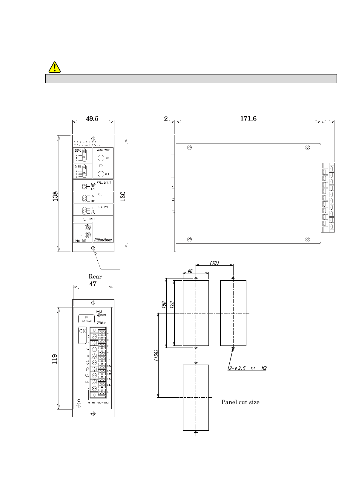
Install based on the following sizes to set up this instrument, and secure the space for surroundings of this container.
Unit:mm
Front
Side
Rear
Panel cut size
or
2-φ4
(20)
② When you set up this instrument
Warning
Each dimensions of the instrument and required dimensions for the environmental spaces are as
follows:
Page 6
IV
Install each cable while turned off the power supply. Might it get an electric shock, and this instrument be damaged when working with the
power supply enters.
Confirm the indication of the power supply voltage of the instrument and the specifications are corresponding to the supplied power supply
before turning on the power supply. Consult with MINEBEA when not matching. There is danger of causing damage and the electric shock of
this instrument when using it like the uncertainty.
Groundline should be connected securely. When groundline is not connected, it may cause a malfunction of the instrument or el ectric shock to
the operator
Before this instrument is newly used, or when the strain gage applied transuducer is exchanged with a new one, please execute the calibration.
If not calibrating, it may cause not obtaining the correct measurement result, or a malfunction in the instrument and there i s a possibility of the
damage of peripherals. Moreover, there is a similar possibility that the result is incorrect even if the calibration has been already made. Please
take the calibration again.
Please confirm connecting wires is correctly executed when you use this instrument. If it is not connected correctly, it may cause the
malfunctions on the instrument, and the damage to the peripheral equipments or even worse serious accidents.
CautionIt causes not obtaining a correct measurement result, and the malfunction when the setting change is carelessly executed while
measuring it with this instrument and there is a possibility of the damage of peripherals.。
Please do not give the impact such as throwing the thing at this instrument.
There is a possibility of causing the malfunction on this instrument, or causing the damage of the electric circuit.
2. Power supply
Warning
Warning
Caution
3. Application note
Caution
Caution
Caution
Caution
Page 7

V
Please observe the following conditions strictly when this instrument suits the above−mentioned standard.
If neglected, there is a possibility of not suiting the above−mentioned standard.
4. CE conformity standard
This instrument has suited the following standard.
EN61326−1:2006
“Electrical equipment for measurement, control, and laboratory use − EMC requirements”
“Immunity test requirements for equipment intended for use in industrial locations”
EN61010−1:2001
“Safety requirements for electrical equipment for measurement, control and laboratory use”
The operating condition to conform this standard is as follows :
Caution
4-1. Place of installation
Please set up this instrument in the shielded case or control panel where EMC measures are
given.
4-2. Wiring
① Shield processing
Please make sure to shield all the signal cable by using the shielded cable or using the conduit
piping including the storage case and control panel.
Please make sure to shield the power cable by using the conduit piping including the storage case
and control panel.
② Grounding
Please make sure to apply the grounding through the case and control panel where EMC
measures are given with protective earth terminal.
Page 8

VI
Date
Manual No.
Revision reason (Contents)
2007/06
DRW. NO.EN294-1348
First version
2009/06
DRW. NO.EN294-1348-A
Due to ECN.FN09-02035
Changed CE conformity standard EN61326-1:2006
-Addition-
“Immunity test requirements for equipment intended for use in
industrial locations”
2016/10
DRW. NO.EN294-1348-B
Due to ECN.FN10-02121A
・Change length of terminals (15) to (20)
・Minebea logo is changed
Due to ECN.FN16-02057
・「 MINEBEA Co., Ltd. Measuring Components Business Unit」
on the cover is deleted
2016/10
DRW. NO.EN294-1348-C
Due to ECN.FN10-02121B
・Delete the extra page number .「next page of cover and table
of contents page number Ⅱ」
・Repair the position of word .「Warning」、「!」
・Delete the extra white page .「next page of history of
revision」
・Add the white page .「next page of table of contents」
2016/10
DRW. NO.EN294-1348-D
Due to ECN.FN10-02121C
・Delete the extra white pages .
「next page of History of revision」「next page of Index」
History of revision
Page 9

Index
FORWARD ........................................................................................................................................................ I
MARKS AND ARRANGEMENTS USED IN THIS MANUAL ........................................................................ I
FOR SAFE OPERATION ................................................................................................................................ II
1. INSTRATION PLACE ............................................................................................................................................................................................... II
2. POWER SUPPLY ................................................................................................................................................................................................... IV
3. APPLICATION NOTE ............................................................................................................................................................................................ IV
4. CE CONFORMITY STANDARD ........................................................................................................................................................................... Ⅴ
HISTORY OF REVISION ..............................................................................................................................VI
1. EACH FUNCTION AND NAME .............................................................................................................1
1-1. FRONT PANEL .................................................................................................................................................................................................. 1
1-2. REAR PANNEL .................................................................................................................................................................................................. 2
2. CONNECTING METHOD .......................................................................................................................3
2-1. ALLOCATION OF THE TERMINALS ................................................................................................................................................................ 3
2-2. NOTES ON CONNECTIONS.............................................................................................................................................................................. 4
2-3. CONNECTION WITH STRAIN GAGE APPLIED TRANSDUCER ...................................................................................................................... 4
2-4. CONNECTION WITH POWER SUPPLY AND GROUND ................................................................................................................................... 6
2-5. CONNECTION WITH ANALOG OUTPUT.......................................................................................................................................................... 7
2-6. CONNECTION WITH THE AUTO ZERO BY THE EXTERNAL CONTROL INPUT ........................................................................................... 8
3. CALIBRATION ........................................................................................................................................9
3-1. CALIBRATION METHOD ................................................................................................................................................................................... 9
3-2. CALIBRATION PROCEDURE .......................................................................................................................................................................... 10
4. FUNCTION AND OPERATION ............................................................................................................ 13
4-1. SETTING OF ZERO ADJUSTMENT ............................................................................................................................................................. 13
4-2. SETTING OF GAIN ADJUSTMENT ............................................................................................................................................................... 13
4-3. SETTNG OF CALIB VALUE.......................................................................................................................................................................... 13
4-4. SETTING OF FREQUENCY RESPONSE ......................................................................................................................................................... 13
4-5. SETTING OF BRIDGE POWER SUPPLY VOLTAGE ...................................................................................................................................... 13
5. HOW TO CHANGE THE FUSE ............................................................................................................ 14
6. OPTION ................................................................................................................................................. 15
6-1. AUTO ZERO (CSA522B-P99) .................................................................................................................................................................. 15
6-2. POWER SUPPLY VOLTAGE AC110 V (CSA522B-P61) ...................................................................................................................... 16
6-3. POWER SUPPLY VOLTAGE AC200 V (CSA522B-P63) ...................................................................................................................... 16
Page 10

II
6-4. POWER SUPPLY VOLTAGE AC220 V (CSA522B-P64)...................................................................................................................... 16
7. TROUBLE SHOOTING ......................................................................................................................... 17
8. SPECIFICATIONS ................................................................................................................................ 23
8-1. SPECIFICATIONS ............................................................................................................................................................................................ 23
8-2. GENERAL SPECIFICATION ............................................................................................................................................................................ 23
8-3. ACCESSORIES ................................................................................................................................................................................................ 23
8-4. OPTIONS ......................................................................................................................................................................................................... 24
8-5. STANDARD SPECIFICATION AT THE SHIPMENNT ..................................................................................................................................... 24
9. WARRANTY .......................................................................................................................................... 25
9-1. WARRANTY ..................................................................................................................................................................................................... 25
9-2. REPAIR ............................................................................................................................................................................................................ 25
Page 11
1
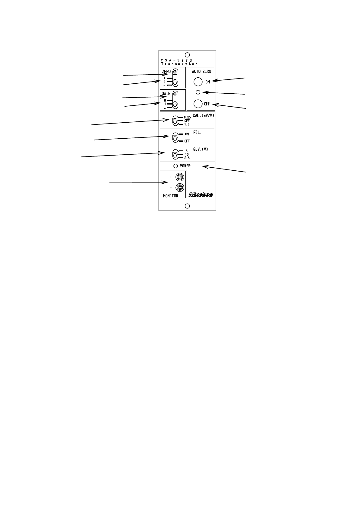
① POWER LED
③ ZERO coarse control switch
② ZERO fine control trimmer
④ GAIN fine control trimmer
⑤ GAIN coarse control switch
⑥ CALIB switch
⑦ FILTER switch
⑩ AUTO ZERO LED
⑨ MONITOR terminal
⑧ GV switch
⑫ AUTO ZERO OFF switch
⑪ AUTO ZERO ON switch
1. Each function and name
1-1. Front panel
① POWER LED
It lights by turning on the power supply (POWER switch ON).
② ZERO Fine control trimmer
It is a trimmer for the fine control of zero.
③ ZERO Coarse control switch
It is a switch for the coarse control of zero. Some ±0.3mV/V input is shifted.
④ GAIN Fine control trimmer
It is a trimmer for the fine control of amplification degree.
⑤ GAIN Coarse control switch
It is a trimmer for the coarse control of amplification degree. It is 1000 times in L, 2000 times in M,
and 3000 times in H.
⑥ CALIB switch
It is a switch that turns the CAILB value on and off.
⑦ FILTER switch
It is a switch that changes the frequency response.
It is 25 kHz in OFF, and 1 Hz or 30 Hz in ON. (Change with the DIP switch on the circuit board.)
⑧ GV switch
The power supply voltage of the bridge to the strain gage applied transducer is selected.
⑨ MONITOR terminal
It is a terminal to monitor the output voltage value.
⑩ AUTO ZERO LED (Options)
LED lights while auto zero executions
⑪ AUTO ZERO ON switch (Options)
The analog output when pushing is adjusted to 0 volt.
Please release the auto zero when you calibrate.
⑫ AUTO ZERO OFF switch (Options)
Auto zero is released.
Page 12
2
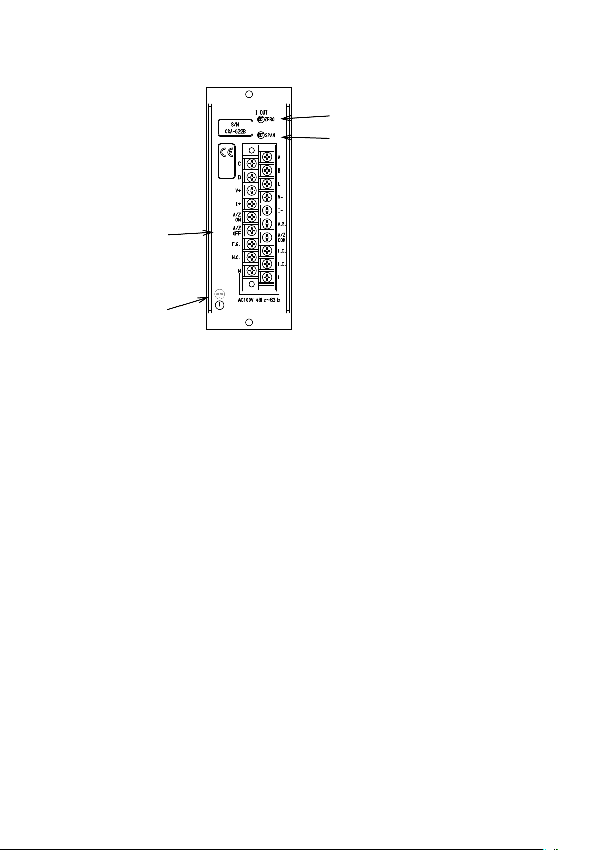
① Termnal board
③ I-OUT SPAN fine control trimmer
② I-OUT ZERO fine control trimmer
④ protective
earth terminal
1-2. Rear pannel
① Terminal board
The vaious strain gage applied transducers like load cell, etc., voltage output, current output,
external control input (Option), grounding wire and AC power supply are connected.
② I-OUT ZERO fine control trimmer
It is the fine control trimmer of the current output (DC4 mA).
③ I-OUT SPAN fine control trimmer
It is the fine control trimmer of the current output (DC20 mA).
④ Protective earth terminal
Connect the grounding line to suit the CE Conformity Standard.
Do not connect excluding the grounding wire.
Page 13

3
Name of terminal
Description
Usage
A
Bridge power supply(+)
Strain gage applied transducer
C
Bridge power supply (-)
D
Amplifier input (+)
B
Amplifier input (-)
E
Shield
A.G.
Analog ground
For check
F.G.
Frame groung
F.G.
Frame groung
F.G.
Frame groung
V +
Voltage output terminal(+)
Voltage output
V -
Voltage output terminal (-)
I +
Current output terminal (+)
Current output
I -
Current output terminal (-)
A/Z ON
Terminal for AUTO ZERO ON control
External control input
(Option)
A/Z OFF
Terminal for AUTO ZERO OFF control
A/Z COM
Common for controling auto zero
N.C.
No use
Do not use.
L
Power supply input terminal (L)
Power supply
N
Power supply input terminal (N)
Protective earth terminal
● The terminal F.G. and the terminal E are connected internally.
● The terminal A.G. and the terminal V-OUT (-), the terminal I-OUT (-) are connected internally.
2. Connecting method
2-1. Allocation of the terminals
Page 14

4
Width of crimp type terminal lugs
Suitable crimp type terminal lugs
6.0 mm or less
1.25-3 or Y-type 1.25-3.5
● When tension load is applied with the application of tension type or universal (compression / tension) type of load cell, and output of “+”
direction is required, please replace and connect "Amplifier input +” and "Amplifier input –”.
● When the total length of cable specifies more than 30 m, the accuracy may be out of warranty because the resistance of cable makes the
input voltage of the instrument decreased.
● When the length of cable is applied more than 10 m, or when the system is using the zener barrier, the CALIB value is not applicable.
● When this instrument suits the CE standard, please make sure to shield the signal cable by mounting this in the storage case or control
panel where EMC measures are given with protective earth terminal.
2-2. Notes on connections
● Please go after turning off the power supply without fail when you connect wires.
● Please do not energize the power supply until the installation is completed.
● Keep the connecting cable with the instrument away from the noise source like power supply
line and I/O line for control as far as possible.
● Conduit wiring should be the type of exclusive one, and avoid using with another line together.
● Please connect the earthing cable securely. The earthing should be D class with single earth.
Don’t share with the earth of power supply system.
● The crimp type terminal lugs that suits the terminals of this instrument is as shown in the table
below.
2-3. Connection with strain gage applied transducer
① Case : Connection with one point of strain gage applied load cell
Page 15
5
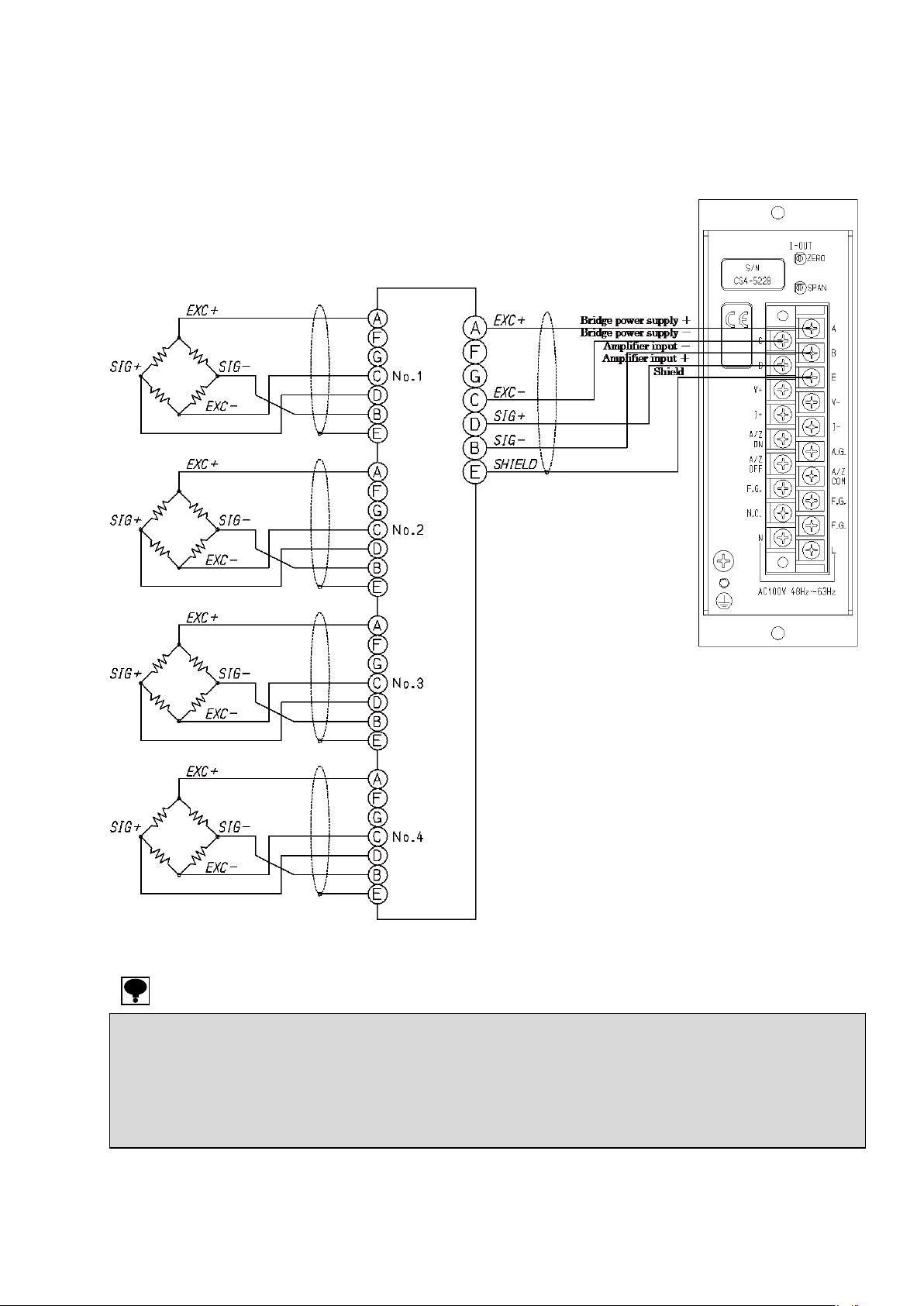
● When tension load is applied with the application of tension type or universal (compression / tension) type of load cell, and output of “+”
direction is required, please replace and connect "Amplifier input +” and "Amplifier input –”.
● When the total length of cable specifies more than 30 m, the accuracy may be out of warranty because the resistance of cable makes the
input voltage of the instrument decreased.
● When the length of cable is applied more than 10 m, or when the system is using the zener barrier, the CALIB value is not applicable.
● When this instrument suits the CE standard, please make sure to shield the signal cable by mounting this in the storage case or control
panel where EMC measures are given with protective earth terminal.
② Case : Connection with 2 to 4 points of strain gage applied transducers.
Plurality of of the strain gauge applied transducers might be connected parallel.
The parallel connection can be easily done by using optional SB-310 and SB-320 (Summing
type junction box).
Page 16
6
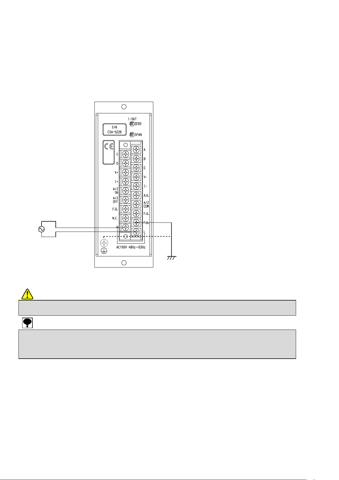
● Connection with power supply and ground should be made securely as the figure indicates and also should be used within the specified
condition of power supply.
● The grounding for the instrument should be the D class with single ground. If negrected, it may cause an unexpected malfunction due to the
effects of noise from the other equipment.
● GND terminal and F.G. terminal is connected with the frame of the instrument.
● When this instrument suits the CE standard, please execute the single ground with protective earth terminal.
D class with single ground
AC100 V
(AC90 V to AC110 V)
2-4. Connection with power supply and ground
The connection with power supply and ground should be made as follows:
Beside, the grounding should be the D class with single ground.
Power supply voltage AC100 V (Permisible variable range AC90 V to AC110 V)
Power supply frequency 50/60 Hz
Power consumption Approx. 15 VA (without any options at AC100 V)
* When the power supply is AC110 V (CSA522B-P61), AC200 V (CSA522B-P63) or AC220 V
(CSA522B-P64), please refer the paragraph 6-2, 6-3 and 6-4.
Caution
Page 17
7
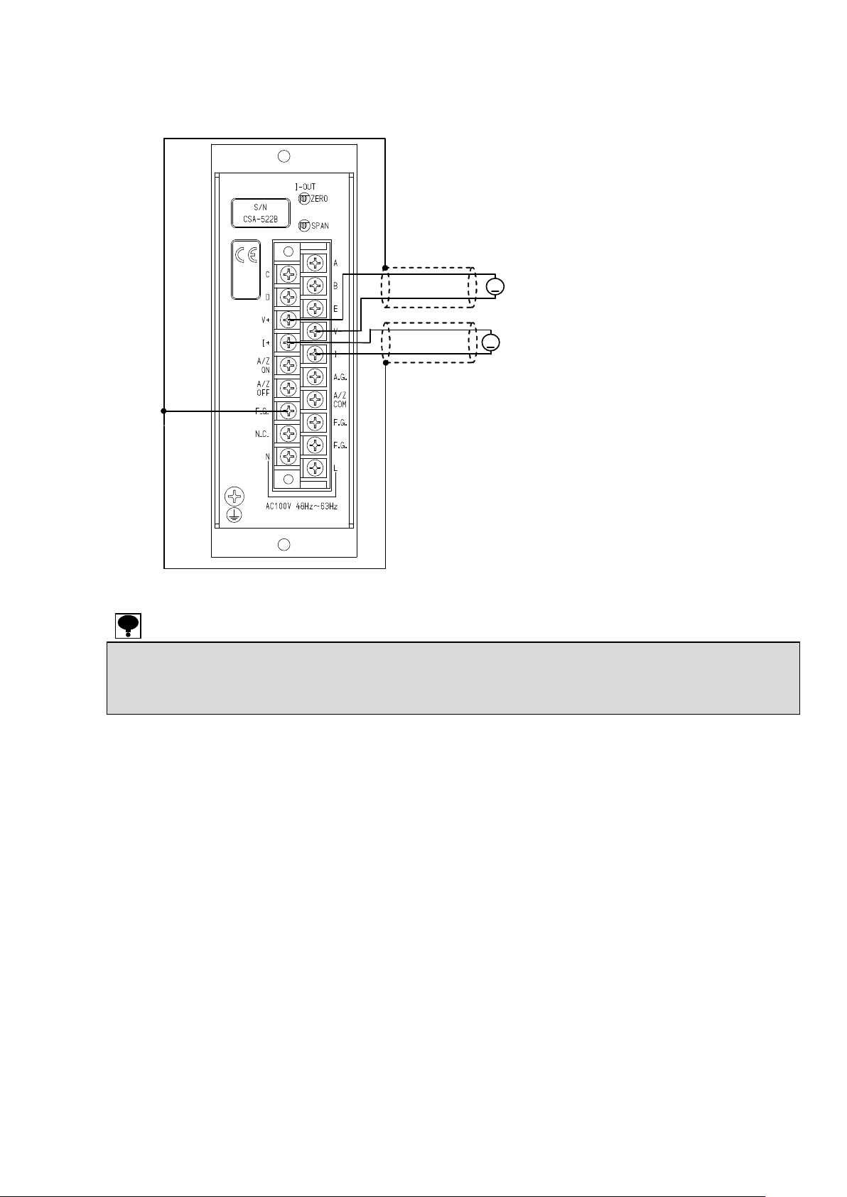
● Please use the shielded cable for the connection with analog output, and connect the shield with F.G. terminal of the terminal block.
There is a possibility of causing the malfunction by the influence of the exogenous noise etc. when not connecting it.
● When this instrument suits the CE standard, please make sure to shield the signal cable by mounting this in the storage case or control
panel where EMC measures are given with protective earth terminal.
V
A
DC0 V to DC10 V
Load resistance 500Ω or more
+
-+-
Shield
Shield
Load resistance 510Ω or less
2-5. Connection with analog output
The connection with analog output should be made as follows:
Page 18
8
● Please use the shielded cable for the connection with analog output, and connect the shield with F.G. terminal of the terminal block.
There is a possibility of causing the malfunction by the influence of the exogenous noise etc. when not connecting it.
● When this instrument suits the CE standard, please make sure to shield the signal cable by mounting this in the storage case or control
panel where EMC measures are given with protective earth terminal.
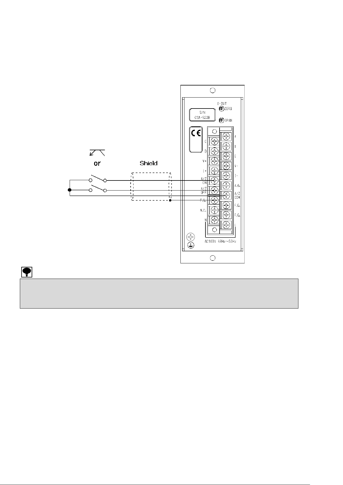
2-6. Connection with the auto zero by the external control input
“A/Z ON” and “A/Z OFF” of the external control input are connected with “COM” terminal by using
the point of contact or open collector connection as shown in the figure below. (Effective when the
optional CSA522B-P99 is installed.)
Please refer the paragraph 6. for the function of each input
Page 19

9
● Before using the new instrument or after exchanging the strain gage applied transducer with a new one, be sure to make calibration. If
calibration is not made, the correct measurement results may not be obtained. or it may cause malfunction to the instrument and it may
damage the peripheral equipment. Moreover, even if calibration has made, there may occur the similar case as above when the result is not
correct. So, make precise calibration again.
● When the auto zero option (CSA-522B-99) is applied, please calibrate with pushing the A/Z OFF switch, or shorten between A/Z OFF and
A/Z COM for about 100 ms or more.
● Please make the calibraton while the CALIB switch turns off.
● The accuracy of calibration by CALIB input is 1/500 or so.
3. Calibration
3-1. Calibration method
The load calibration method of this instrument has two kinds of the following.
① Calibration with actual load
② Electrical calibration by the CALIB input
Caution
Page 20
10
ZERO adjustment
SPAN adjustment
Check the ZERO point
Connect with the strain
gage applied transducer
Energizing for 10 min. after
turning on the power.
Complete
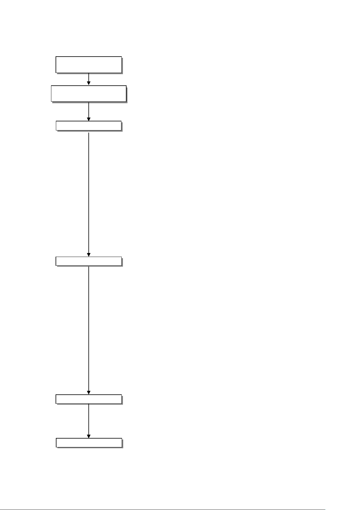
3-2. Calibration procedure
4-6. Calibration by actual load
Step 1 Connect the instrument with strain gage applied transducer.
Step 2 To stabilize this instrument and strain gage applied
transducer, please put it in the condition of energizing for
about 10 min.
Step 3 Please set the condition of the initial weighing (tare weight)
on the strain gage applied transducer.
Please cancel the initial weight (tare) if necessary with the
ZERO coarse control switch.
Some ±0.3 mV/V input shifts on the input conversion by the
ZERO coarse control switch.
Take the fine adjustment to set the voltage output value to
0.000 V or the current output value to 4.000 mA by ZERO fine
control trimmer.
The input of ±0.3 mV/V of input conversion can be changed by
ZERO fine control trimer.
When the voltage output is used together with the current
output, the voltage output is previously adjusted, and then the
current output is adjusted by I-OUT ZERO fine control trimmer
in the rear panel.
Step 4 Put the preliminary test force such as weights (Please use the
one near the preliminary test force as much as possible.) on the
strain gage applied transducer, and then set by GAIN coarse
control switch to become the voltage output value or the current
output value to be set.
The GAIN coarse control switch becomes 3 000 times at H,
2 000 times at M and 1 000 times at L.
Adjust the GAIN fine control trimmer to become the voltage
output value or the current output value to be set.
It comes in changeability by the GAIN fine control trimmer
the range of 1/1 to 1/4 of the full scale.
When the voltage output is used together with the current
output, the voltage output is previously adjusted, and then
adjust the current output by I-OUT SPAN fine control trimmer
in the rear panel.
Step 5 Remove the preliminary test force put in step 4., and confirm
that the voltage output value becomes 0.000 V or the current
output value becomes 4.000 mA.
It returns to step 3 when not becoming it.
Step 6 It is an end of the calibration by an actual load.
Page 21
11
ZERO adjustment
SPAN adjustment
Energizing for about 10 min.
after turns on the power.
Connection with strain
gage applied transducer
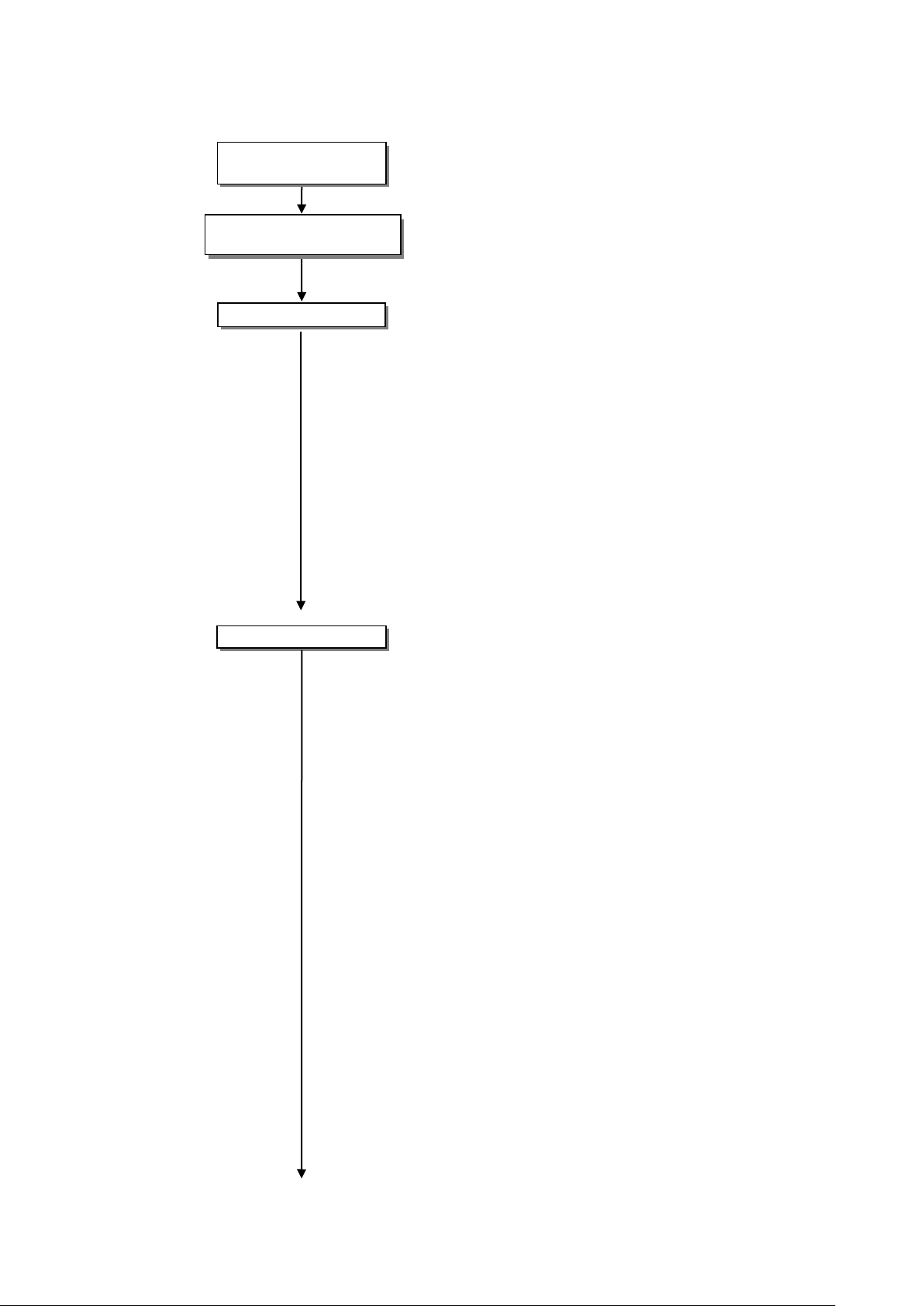
4-7. Calibration by CALIB input
Step 1 Connect this instrument with strain gage applied
transuducer.
Step 2 To stabilize this instrument and strain gage applied
transducer, please put it in the condition of energizing for
about 10 min.
Step 3 Please set the condition of the initial weighing (tare weight)
on teh strain gage applied transducer.
Please cancel the initial weight (tare) if necessary with the
ZERO coarse control switch.
Some ±0.3 mV/V input shifts on the input conversion by the
ZERO coarse control switch.
Take the fine adjustment by using the ZERO fine control
trimmer to set the voltage output value to 0.000 V, or set the
current output value to 4.000 mA.
By using the ZERO fine control trimmer, the input of ±0.3
mV/V is variable in input conversion.
When the voltage output is used together with the current
output, adjust the voltage output previously, then in the next,
adjust the current output by using the fine control trimmer
I-OUT ZERO in the rear panel.
Step 4 Turn on the CALIB switch.
The output that corresponds to the input of 0.25 mV/V
±0.000 25 mV/V and 1.0 mV/V±0.001 mV/V is obtained.
The voltage output value or the current output value which
corresponds to CALIB value is calculated from the rated output
value and the maximum load value of the strain applied
transducer connected, and the voltage output value or the
current output value at that time.
Adjust the voltage output value or the current output value to
become a calcurated value by GAIN coarse control switch and
GAIN fine control trimmer.
When the voltage output is used together with the current
output, adjust the voltage output according to the above
procedure previously, and then, adjust the current output by
I-OUT SPAN fine control trimmer in the rear panel.
[Example of calcurating output value that corresponds to
CALIB value]
It is the case that the voltage output of 10.000 V is required
at the maximum load of 0.34 t when 1 point of load cell with
the rated load of 1 ton and the rated output is 3 mV/V is
applied showing as follows.
Rated capacity of load cell 1 t
Rated output of load cell 3 mV/V
The maximum load value 0.34 t
Voltage output valu at the maximum load. 10.000 V
CALIB value 1 mV/V
Page 22

12
● Please make the rated output value of the load cell used in the caliculatoin with the value written in the individual inspection data sheet.
Confirm ZERO point
=
= =
=
Completing calibration
=
(Load cell output value at the maximum load)
(Rated output value of load cell)×(The maximum load value)
(Rated load value of load cell)
3 mV/V×0.34 t
1 t
1.02 mV/V
(Voltage output value corresponging to CAL value)
(Voltage output value at the maximum load)×(CALIB value)
(Load cell output value at the maximum load)
10.000 V×1 mV/V
1.02 mV/V
≒9.804 V
Accordingly, the voltage output value at turning on the
CALIB switch is adjusted to 9.804 V by GAIN fine control
trimmer.
Step 5 Turn of the CALIB switch.
Confirm to the voltage output value becomes 0.000 V or the
current output value becomes 4.000 mA.
Otherwise, it returns to step 3.
Step 6 The calibration by CALIB input is completed.
Caution
Page 23

13
ZERO coarse control switch
Variable range by ZERO fine control trimmer
+
Approx.0.3 mV/V to Approx.0.6 mV/V
0
Approx. -0.3 mV/V to Approx.0.3 mV/V
―
Approx.-0.6 mV/V to Approx.-0.3 mV/V
GAIN coarse
adjustment switch
Variable range by GAIN
fine control trimmer
Sensitivity
M
0.5 mV/V to 2.0 mV/V
Approx. 500 times to Approx. 2 000 times
H
0.35 mV/V to 1.4 mV/V
Approx. 750 times to Approx. 3 000 times
L
1.0 mV/V to 4.0 mV/V
Approx. 250 times to Approx. 1 000 times
CALIB switch
Input conversion value to be output
0.25 mV/V
0.25 mV/V±0.000 25 mV/V
OFF
0 mV/V
1.0 mV/V
1.0 mV/V±0.001 mV/V
FILTER switch
Frequency response
Attenuation rate
ON
1 Hz or 30 Hz
-12 dB/oct bessel type
OFF
25 kHz
-6 dB/oct
G.V. switch
Bridge power supply voltage
5 V
5 V±0.15 V
10 V
10 V±0.3 V
2.5 V
2.5 V±0.075 V
● Please execute the calibration again when the bridge power supply voltage is changed.
4. Function and operation
4-1. Setting of ZERO adjustment
Zero point can be changed by ZERO coarse control switch and ZERO fine control trimmer.
4-2. Setting of GAIN adjustment
Sensitivity can be changed by GAIN coarse control switch and GAIN fine control trimmer.
The variable range above mentioned is input conversion to get the output of DC10V.
(When the bridge power supply voltage is set as DC10V.)
4-3. Settng of CALIB value
The voltage or the current corresponding to the CALIB set value (input conversion value) is
output.
4-4. Setting of frequency response
Frequency response can be selectable.
The changeover of 1 Hz and 30 Hz at FILTER ON is selected by DIP switch on circuit board.
When both 1 and 2 of DIP1 on the printed cirsuit board turns OFF, 1 Hz is selected.
(The standard is 30 Hz. The setting is that both 1 and 2 of DIP1 turns ON.)
4-5. Setting of bridge power supply voltage
The bridge power supply voltage is selectable.
Please select the voltage value less than the maximum rated voltage of a strain gage applied
transducers.
Page 24

14
● When the procedure of installing the fuse, and the capacity of installed fuse is improper, it will cause an unexpected failure.
Position of fuse
Parts mountin g side of the PCB
5. How to change the Fuse
Caution
① Turn off the power supply to the terminal of this instrument.
② Detach the screw (M2.6 x 5) of 4 points at the right side of the front panel, and remove the cover.
③ Replace the fuse (1 A) attached at the parts mounting side of PCB showing as follows.
④ Put the cover, and install the screw to 4 points.
Page 25

15
● Dont press the A/Z ON switch in the condition of pressing the A/Z OFF switch. It enters the adjustment mode for our maintenance, and it
becomes a fixed output of DC0 V compulsorily, and AUTO ZERO LED blinks.
Please push the A/Z ON switch with the A/Z OFF switch pushed again, and make clear the adjustment mode when it enters the adjustment
mode by mistake.
● The operation of A/Z ON and A/Z OFF by the external control input is started when the input signal is shorten for about 100 ms or more.
● Don’t execute the A/Z OFF during the 1 second executing the A/Z ON by the external control input and the switch at the front panel.
● When the optional auto zero is attached, the temperature effect of auto zero is added on the standard temperature effect.
● When the condition changes by the external control input, please confirm the timing of the changeover, and adjust the timing by processing
the timer if necessary.
6. Option
6-1. Auto zero (CSA522B-P99)
(1) Input range of auto zero :within ±2.4 mV/V
(2) Range of auto zero :within ±10 V
(3) Required time of auto zero :within approx.1 s
(4) Accuracy of auto zero :within ±5 mV
(5) Back-up time :Approx. 10 years (under the usage of Lithem battery)
(6) Temperature effect Zero point :within ±0.005 %F.S./℃
Sensitivity :within ±0.005 %F.S./℃
6-1-1. Equivalent circuit of external input
6-1-2. Explanation of the function
(1) A/Z ON
When the “A/Z ON” switch at the front panel is pressed, or shorten the terminal between A/Z
ON and COM for about 100 ms or more, auto zero (tare weight cancellation) is executed, and
teh voltage output value and the current output value becomes zero. The voltage output value
or the current output value becomes the output for net weight.
(2) A/Z OFF
When pressing the “A/Z OFF” switch, or shorten the terminal between A/Z OFF and COM for
about 100 ms or more, the function of auto zero clear (tare weight cancellation clear) will work.
The voltage output value or the current output value becomes the output of gross weight.
Caution
Page 26

16
6-2. Power supply voltage AC110 V (CSA522B-P61)
Power supply voltage AC110 V (Permissible variable range AC99 V to AC127 V)
Power supply frequency 50/60 Hz
Power consumption Approx.15 VA
6-3. Power supply voltage AC200 V (CSA522B-P63)
Power supply voltage AC200 V (Permissible variable range AC180 V to AC220 V)
Power supply frequency 50/60 Hz
Power consumption Approx.15 VA
6-4. Power supply voltage AC220 V (CSA522B-P64)
Power supply voltage AC220 V (Permissible variable range AC198 V to AC253 V)
Power supply frequency 50/60 Hz
Power consumption Approx.15 VA
Page 27
17
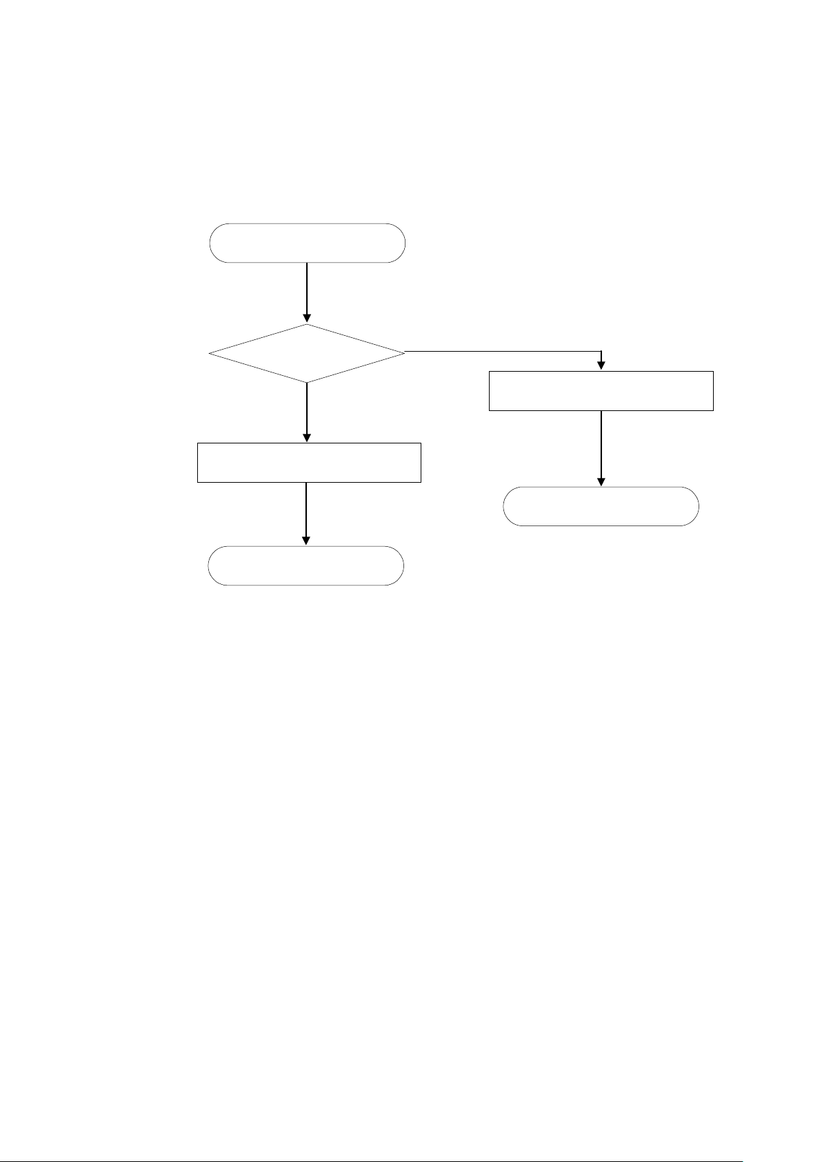
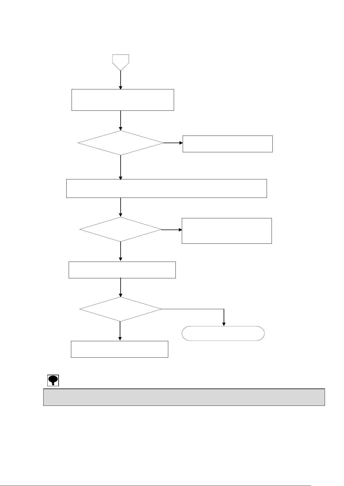
Execute the trouble shooting
Start measurement
NG
OK
Normal operation
Supply power again
Operation
Abnormal operation
7. Trouble shooting
Please check the instrument according to the following procedures when abnormality is found in
operation.
Moreover, please contact with MINEBEA when there is no corresponding item, and the symptom does
not disappear even if the solution is done.
Page 28

18
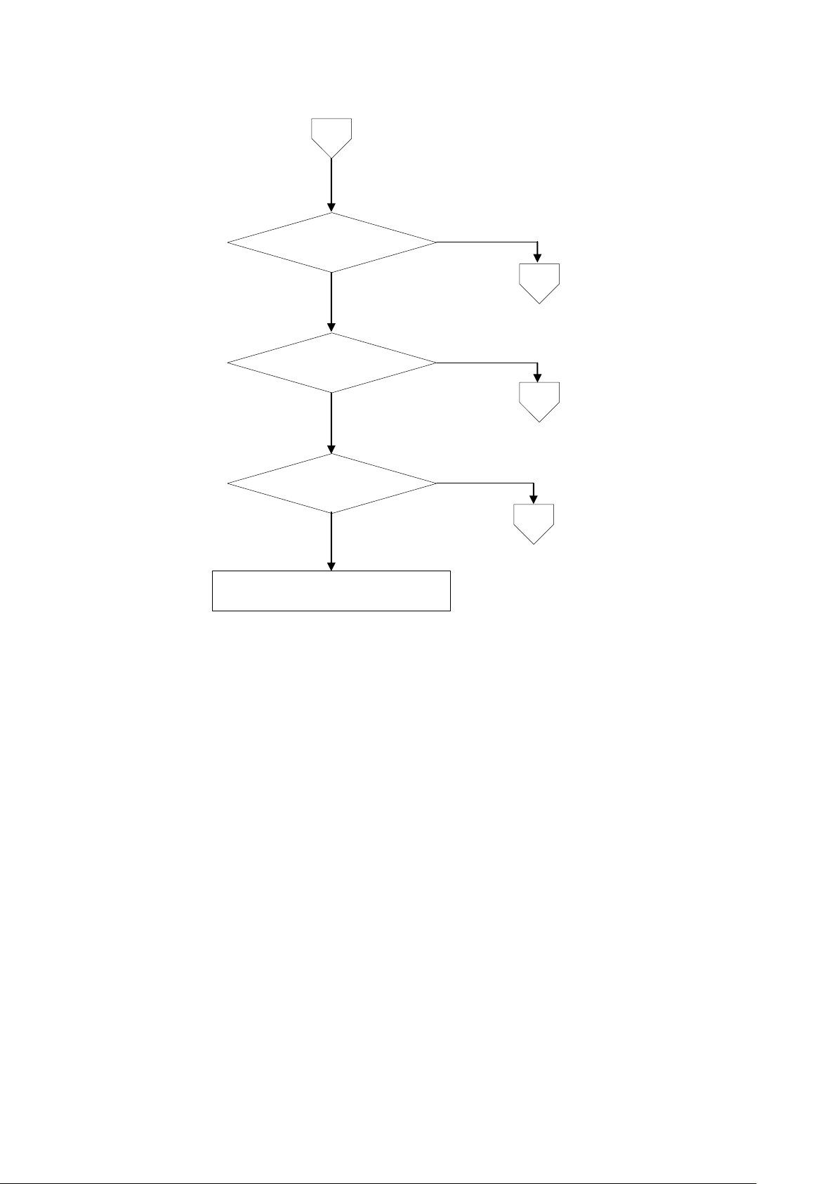
YES
NO
Inform Minebea about the contents of
failure and situation at site in details.
Supply power source suitable for the
spedification
Set the load resistance
to 500 Ω or more
NO
YES
YES
1
Set the load resistance
to 510 Ω or less
Load resistance is
510 Ω or less
1
NO
NO
YES
YES
Wiring method
is good
YES
YES
YES
NO
NO
NO
NO
According to the
paragraph 2-6. connect
the wiring correctly.
Set within the operation
range of auto zero.
Does supply
power voltage satisfy
the specification
Executing the trouble shooting
Voltage output is
wrong
Within the range of
auto zero
Current output
is wrong
Load resistance is
500 Ω or more
Auto zero does’t
work
Page 29
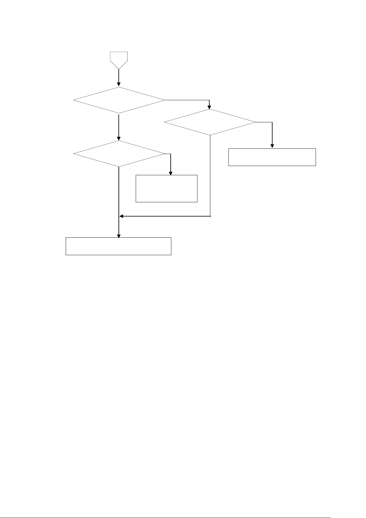
19
Output the voltage
and current
Output of voltage or
current doesn’t change
NO
NO
YES
YES
2
3
Voltage and
current output stagger
abnormally.
4
YES
NO
Inform Minebea about the contents of
failure and situation at site in details.
1
Page 30
20
POWER LED lights on
Connect securely according to
the paragraph 2
Fuse is cut off
Replace fuse
according to the
paragraph 5
NO
NO
NO
YES
YES
YES
Inform Minebea about the contents of
failure and situation at site in details.
Connecting method
is good
2
Page 31
21
● In confirming the voltage between A and C, please set the connection range of the measuring instrument such as tester to DC・V.
● In confirming the voltage between B and D, please set the connection of the measuring instrument to DC・mV.
Remove the cable of strain gage applied
transducer from the terminal.
Voltage betwee A and C
is the same as specified.
① Connect the cable of strain gage applied transducer to the terminals again.
② Apply the load to the strain gage applied transducer while inspecting the
voltage between the terminal B and D.
Voltage between B
and D is varied.
Execute the calibration again according to
the paragraph 3.
Same condition
Start measurement
Consult with MINEBEA
3
YES
NO
NO
Strain gage applied transducer
connected might be broken, or the
signal route (signal line) might
been disconnected.
YES
NO
YES
Inform Minebea about the contents of
failure and situation at site in details.
Page 32

22
● In confirming the voltage between A and C, please set the connection range of the measuring instrument such as tester to DC・V.
● In confirming the voltage between B and D, please set the connection of the measuring instrument to DC・mV.
Remove the cable of strain gage applied
transducer from the terminal
Shorten between B & D, and A & G
Voltage/Current output
are stable
Same condition
Start measurement
4
YES
NO
NO
YES
NO
Inform Minebea about the contents of
failure and situation at site in details.
Confirm various connection according to the paragraph 2.
Especially, please confirm whether there is influence from the
noise source such as inverters.
Inform Minebea about the contents of
failure and situation at site in details.
YES
Voltage between A & C
is the same as specified, and
stable.
Page 33

23
Bridge power supply
DC10 V±0.3 V within 120 mA (Changeable to DC2.5 V and DC5 V)
Applicable transducer
Strain gage applied transducer from 60 Ω to 2 kΩ
Input range
0.35 mV/V to 3.5 mV/V
Output
±10 V, ±20 mA(Non-isolation)
Load resistance on output
500 Ω or more
Adjustable range on sensitivity
L:1 000 times, M:2 000 times, H:3 000 times
Adjusted 1/1 to 1/4 against each setting
Adjustable range on zero point
±0.6 mV/V
Non-linearity
0.005 %F.S.
Temperature
coefficient (voltage)
Zero point
±0.2 μV/℃(Input conversion)
Sensitivity
±0.005 %F.S./℃
CALIB
0.25 mV/V±0.000 25 mV/V and 1 mV/V±0.001 mV/V
Frequency responce
1 Hz or 30 Hz (-12 dB/oct) Bessel type
(Selectable by dip-switch on P.C. board) and 25 kHz (-3 dB)
Current output
DC4 mA to 20 mA (Non-isolation, at the output of DC0 V to 10 V)
Load resistance on current output
510 Ω or less
Non-linearity on current output
0.05 %F.S. or less
Temperature
coefficient
(Current)
Zero point
±0.01 %F.S./℃
Sensitivity
±0.01 %F.S./℃
Operating
temperature
/humidity range
temperature
-10 ℃ to 50 ℃
humidity
85 %RH or less (Non condensing)
Power supply
Power supply
voltage
AC100 V (Permisible variable range AC90 V to AC110 V)
Power supply
frequency
50/60 Hz
Power
consumption
Approx.15 VA
Insuration resistance
DC500 V 100 MΩ or more between the power supply line and case
Withstand voltage
AC1 500 V in 1 min. between the power supply line and case
Outline dimensions(W×H×D)
49.5 mm ×138 mm ×173.6 mm (Excludes protruding parts.)
Weight
Approx.1.2 kg
Instruction manual
1 piece
Time lag fuse
1 piece(1 A)
Minus driver
1 piece
8. Specifications
8-1. Specifications
8-2. General specification
8-3. Accessories
Page 34

24
P/N
CSA522B-P99
Input range of auto zero
within ±2.4 mV/V
auto zero range
within ±10 V
Required time for auto zero
within approx.1 s
Accuracy of auto zero
within ±5 mV
Back-up time
Approx. 10 years (with the usage of Lithium battery)
Temperature
coefficient
Zero point
±0.005 %F.S./℃
Sensitivity
±0.005 %F.S./℃
P/N
CSA522B-P61
Power supply voltage
AC110 V (Permissible variable range AC99 V to AC127 V)
Power supply frequency
50/60 Hz
Power consumption
Approx. 15 VA
P/N
CSA522B-P63
Power supply voltage
AC200 V (Permissible variable range AC180 V to AC220 V)
Power supply frequency
50/60 Hz
Power consumption
Approx. 15 VA
P/N
CSA522B-P64
Power supply voltage
AC220 V (Permissible variable range AC198 V to AC253 V)
Power supply frequency
50/60 Hz
Power consumption
Approx. 15 VA
Bridge power supply
DC10 V
Sensitivity adjustment
1 000 times (DC10 V output at 1.0 mV/V input)
Range of frequency responce
30 Hz (-12 dB/oct) Bessel type, and 25 kHz (-3 dB)
8-4. Options
8-4-1. Auto zero
8-4-2. Power supply voltage
8-5. Standard specification at the shipmennt
Page 35

25
9. Warranty
9-1. Warranty
● The instrument is covered by a warranty for a period of one year from the date of delivery.
● As for repairs and/or after service is required during the period of warranty, contact with
Minebea's sales office or sales agent from which you have purchased.
9-2. Repair
Before asking repairs, make checks once again that the connection, setting and adjustment for
the instrument have finished properly by referring to 9. Trouble shooting.
Especially, make checks whether the connections of sensors are disconnected or cut off.
After that, still there may be found some defects in the instrument, contact with Minebea's
sales office or sales agency from which you have purchased.
Page 36

Page 37

Page 38

●The contents of this manual may subject to change without notice.
HEAD QUARTER: MINEBEA CO., LTD.
4106-73 Miyota, Miyota-machi, Kitasaku gun, Nagano-ken 389-0293 Japan
Tel: +81-267-32-2200 Fax: +81-267-31-1350
Sensing Device Product Sales Management:
1-1-1, Katase, Fujisawa-shi, Kanagawa-ken, 251-8531 Japan
Tel: +81-466-23-2681 Fax: +81-466-22-7191
Sensing Device Business Unit
FUJISAWA PLANT 1-1-1, Katase, Fujisawa-shi, Kanagawa-ken, 251-8531 Japan
Tel: +81-466-22-7151 Fax: +81-466-22-1701
KARUIZAWA PLANT 4106-73 Miyota, Miyota-machi, Kitasaku gun, Nagano-ken 389-0293 Japan
Tel: +81-267-31-1309 Fax: +81-267-31-1353
HOMEP AGE ADDRESS http://www .minebea-mcd.com
 Loading...