


M21125/M21115 Evaluation Module
User Guide
21125-EVMD-001-B
July 2013

Revision History
Revision Date Description
B July 2013 Updated High Speed output settings, Tab le 2- 3
A February 2009 Initial release
Added Software Operation, Chapter 3
21125-EVMD-001-B Mindspeed Technologies
®
Mindspeed Proprietary and Confidential
2

Contents
1.0 Introduction . . . . . . . . . . . . . . . . . . . . . . . . . . . . . . . . . . . . . . . . . . . . . . . . . . . . . . . . . . . . . . . . . . . . 4
2.0 Quick Start Guide . . . . . . . . . . . . . . . . . . . . . . . . . . . . . . . . . . . . . . . . . . . . . . . . . . . . . . . . . . . . . . . . 5
3.0 Software Operation . . . . . . . . . . . . . . . . . . . . . . . . . . . . . . . . . . . . . . . . . . . . . . . . . . . . . . . . . . . . . . 11
3.1 Software Setup . . . . . . . . . . . . . . . . . . . . . . . . . . . . . . . . . . . . . . . . . . . . . . . . . . . . . . . . . . . . . . . . . . . . . . . . . . . .11
3.2 Software Operation . . . . . . . . . . . . . . . . . . . . . . . . . . . . . . . . . . . . . . . . . . . . . . . . . . . . . . . . . . . . . . . . . . . . . . . . .13
3.2.1 Connection Settings . . . . . . . . . . . . . . . . . . . . . . . . . . . . . . . . . . . . . . . . . . . . . . . . . . . . . . . . . . . . . . . . .13
3.2.2 Resetting the Device. . . . . . . . . . . . . . . . . . . . . . . . . . . . . . . . . . . . . . . . . . . . . . . . . . . . . . . . . . . . . . . . .13
3.2.3 Direct/Indirect Write Mode . . . . . . . . . . . . . . . . . . . . . . . . . . . . . . . . . . . . . . . . . . . . . . . . . . . . . . . . . . . .14
3.2.4 Memory Map . . . . . . . . . . . . . . . . . . . . . . . . . . . . . . . . . . . . . . . . . . . . . . . . . . . . . . . . . . . . . . . . . . . . . .15
3.2.5 Direct Register Access . . . . . . . . . . . . . . . . . . . . . . . . . . . . . . . . . . . . . . . . . . . . . . . . . . . . . . . . . . . . . . .16
3.2.6 Saving/Loading State and Macro Files . . . . . . . . . . . . . . . . . . . . . . . . . . . . . . . . . . . . . . . . . . . . . . . . . . .16
21125-EVMD-001-B Mindspeed Technologies
®
Mindspeed Proprietary and Confidential
3

1.0 Introduction
This user guide describes how to use the M21125/M21115 evaluation module (EVM). The M21125 is a 40 input by
40 output crosspoint switch and the M21115 is a 20 input by 20 output crosspoint switch rated to operate up to 3.8
Gbps. The EVM is a demonstration and test platform that enables system developers and product designers to
quickly evaluate the functionality and performance of the M21125 and M21115.
The EVM is a single PC board that provides access to 16 lanes of the crosspoint switch (XPTS). One group of four
lanes is accessed via HDMI connectors, another group of four lanes is accessed via DVI connectors, and the
remaining two groups of four lanes are accessed via SMA connectors. The HDMI and DVI connectors are DCcoupled to allow for direct connection to cables interfaced to TMDS sources and sinks. The SMA connectors are
AC-coupled to enable connections to laboratory test equipment such as generators and analyzers. The EVM is
powered utilizing the supplied AC adapter, and controlled with on-board DIP switches. Note that when the EVM is
populated with a M21115 component, the HDMI connectors cannot be used.
21125-EVMD-001-B Mindspeed Technologies
®
Mindspeed Proprietary and Confidential
4
2.0 Quick Start Guide
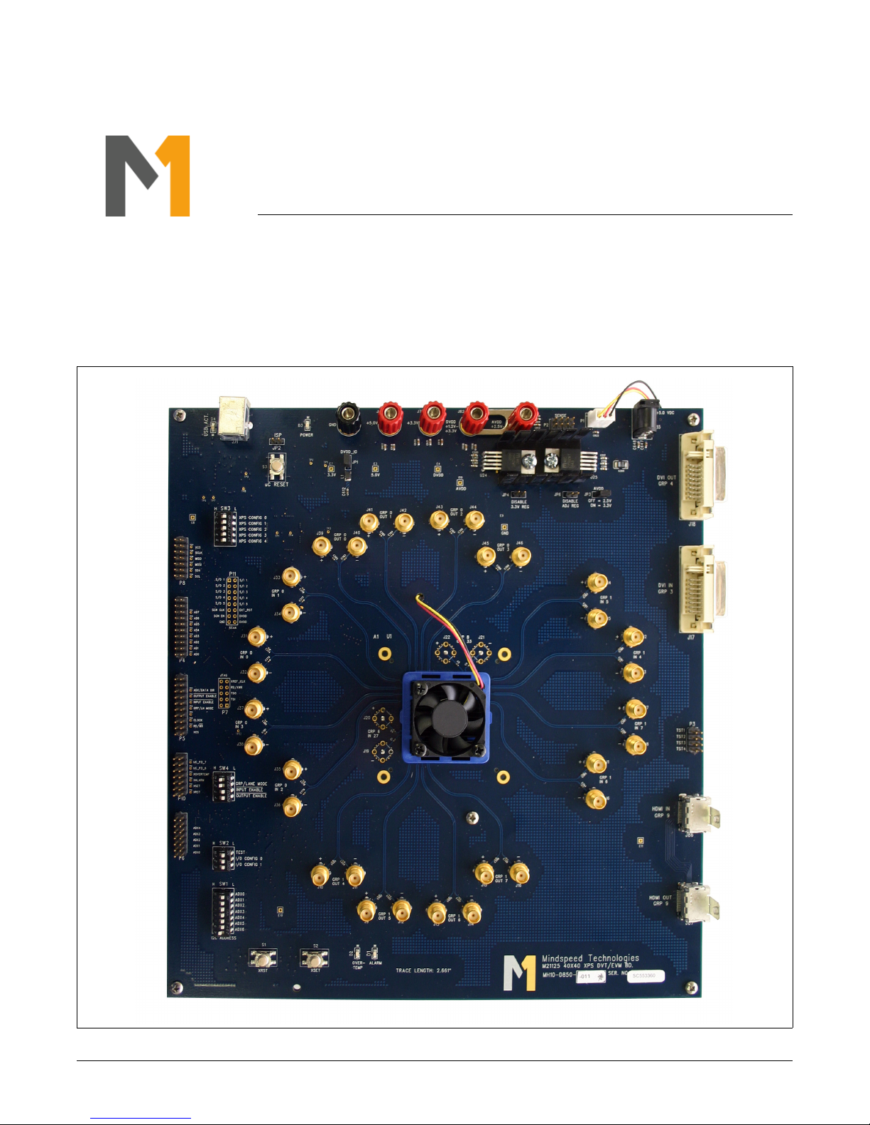
The EVM is ready to use out of the box. Please refer to Figure 2-1 for the location of the various connectors.
Figure 2-1. M21125/M21115 Evaluation Module
21125-EVMD-001-B Mindspeed Technologies
®
Mindspeed Proprietary and Confidential
5

1. Connect the supplied AC adapter to connector J85 (+5.0 VDC).
2. For HDMI evaluations, attach an HDMI cable from the source to the connector labeled HDMI IN (J86) and an
HDMI cable from the sink to the connector labeled HDMI OUT (J87). Note that when the EVM is populated with
a M21115 component, the HDMI connectors cannot be used.
3. For DVI evaluations, attach a DVI cable from the source to the connector labeled DVI IN (J17) and a DVI cable
from the sink to the connector labeled DVI OUT (J18).
4. In addition, the SMA connectors can be used for an AC-coupled interface to test equipment. Signal generators
should be connected to the EVM by securing 50 cables to the SMA connectors labeled IN[7:0], and signal
analyzers should be connected to the EVM by securing 50 cables to the SMA connectors labeled OUT[7:0].
Note that the EVM is pre-configured for pass-through mode, routing GRP0 IN0 to GRP0 OUT0, GRP0 IN1 to
GRP0 OUT1, … , GRP1 IN7 to GRP1 OUT7.
5. The crosspoint switch state can be altered utilizing DIP switches XPS CONFIG[1:0] located at SW3, as shown
in Ta bl e 2 -1. The EVM has been pre-configured for the group switch mode, where groups of four lanes are
switched at a time. Group 0 consists of inputs/outputs [3:0] and group 1 consists of inputs/outputs [7:4]. See
Ta bl e 2 -2 for the input/output mapping for two of the switch states. After the DIP switches have been
reconfigured it is necessary to push the button labeled uC RESET located at S3; see Figure 2-2.
Table 2-1. Crosspoint Switch State Configuration
XPS CONFIG[1:0] Input Output
LL GRP0 GRP0
GRP1 GRP1
HDMI HDMI
DVI DVI
LH GRP0 GRP1
GRP1 GRP0
HDMI DVI
DVI HDMI
HL GRP0 HDMI
GRP1 DVI
HDMI GRP0
DVI GRP1
HH GRP0 DVI
GRP1 HDMI
HDMI GRP1
DVI GRP0
21125-EVMD-001-B Mindspeed Technologies
®
Mindspeed Proprietary and Confidential
6

Table 2-2. Input/Output Mapping Examples
XPS CONFIG[1:0] Input Output
LL IN0 OUT0
IN1 OUT1
IN2 OUT2
IN3 OUT3
IN4 OUT4
IN5 OUT5
IN6 OUT6
IN7 OUT7
LH IN0 OUT4
IN1 OUT5
IN2 OUT6
IN3 OUT7
IN4 OUT0
IN5 OUT1
IN6 OUT2
IN7 OUT3
21125-EVMD-001-B Mindspeed Technologies
®
Mindspeed Proprietary and Confidential
7

6. Signal conditioning settings such as input equalization (IE) and output de-emphasis (DE) can be configured
utilizing DIP switches XPS CONFIG[4:2] located at SW3, as shown in Ta bl e 2 -3. The EVM has been preconfigured for the DIP switch setting XPS CONFIG[4:2] = HLH. After the DIP switches have been reconfigured
it is necessary to push the button labeled uC RESET located at S3; see Figure 2-2.
Table 2-3. Input Equalization and Output De-Emphasis Configuration
XPS CONFIG[4:2] IE Level DE Level Output Swing
LLL Disabled Low 1000 mVppd
LLH Disabled Medium 1000 mVppd
LHL Disabled High 1000 mVppd
LHH Low Low 1000 mVppd
HLL Medium Low 1000 mVppd
HLH High Low 1000 mVppd
HHL High High 1000 mVppd
HHH High High 1400 mVppd
Figure 2-2. Location of DIP Switch Bank SW3 and Button S3
21125-EVMD-001-B Mindspeed Technologies
®
Mindspeed Proprietary and Confidential
8

7. Verify the settings of the following DIP switches located at SW4 and SW2. Figure 2-3 shows the location of
these DIP switches.
a. GRP/LANE MODE = H
b. INPUT ENABLE = L
c. OUTPUT ENABLE = L
d. TEST = L
e. I/O CONFIG0 = L
f. I/O CONFIG1 = L
Figure 2-3. Location of DIP Switch Banks SW4 and SW2
21125-EVMD-001-B Mindspeed Technologies
®
Mindspeed Proprietary and Confidential
9

8. Perform the desired electrical evaluations. Figure 2-4 shows a typical eye diagram.
Figure 2-4. Typical Data Output Eye Diagram at 3.8 Gbps
21125-EVMD-001-B Mindspeed Technologies
®
Mindspeed Proprietary and Confidential
10

3.0 Software Operation
3.1 Software Setup
Before using the EVM, install the control software on the host PC.
1. Insert the EVM CD or USB flash drive into the computer that will be used as the controller for the EVM. Locate
the “\Software\Mindspeed 8-bit EVM Setup vX.X” folder and launch Setup.exe to install the software. Please
note that Windows XP Service Pack 2 is the minimum system requirement for this software.
2. Connect a USB cable to the EVM and the PC. When the USB cable is connected, a new hardware found
window may pop up and install the USB driver. Allow this process to complete before proceeding.
3. Launch the Mindspeed 8-bit EVM User Control software by going to Start > All Programs > Mindspeed
Technologies.
Figure 3-5. Mindspeed EVM Software (before connection)
21125-EVMD-001-B Mindspeed Technologies
®
Mindspeed Proprietary and Confidential
11

4. Once the software is running, set the “Use Page Select” setting to checked.
Figure 3-6. Use Page Select Setting
5. Next, click the “Connect” button in the top-left corner of the screen. Most settings will be auto-detected, but you
will be prompted if additional information is required (see Section 3.2.1).
6. Once connected, it is generally a good practice to reset the device using the supplied configuration file (see
Section 3.2.2).
21125-EVMD-001-B Mindspeed Technologies
®
Mindspeed Proprietary and Confidential
12

3.2 Software Operation
3.2.1 Connection Settings
In most cases, simply clicking the “Connect” button will auto-detect all settings necessary to connect to the device.
However, if changes to the connection settings need to be made, click the settings icon next to the Connect button
and adjust the settings in the drop-down panel that appears.
For the M21125/15, make sure that “I
The software may also be operated without a device plugged in by turning “Simulate Connection” on. This is useful
primarily for getting familiarized with the interface or reviewing the available device settings.
Figure 3-7. Connection Settings Panel
2
C” is selected.
3.2.2 Resetting the Device
In order to reset this device to the default settings, Mindspeed has provided a configuration file that can be loaded
after connection.
1. Click the “Load” button in the toolbar.
2. In the File Selection dialog that appears, navigate to “Software\Scripts” and select the “Reset.txt” file.
3. Click “Open.”
The details of the “Load” button are described in greater detail in Section 3.2.6.
21125-EVMD-001-B Mindspeed Technologies
®
Mindspeed Proprietary and Confidential
13

3.2.3 Direct/Indirect Write Mode
The Mindspeed EVM software has two modes of operation, and can be switched between them at any time by
clicking the “Direct Write” check-box located in the toolbar (see Figure 3-8).
Figure 3-8. Mindspeed GUI Toolbar
Direct Write Mode
In this mode any changes made in the software are immediately written to the device without any further actions
necessary. When a direct-write occurs, the field will momentarily flash red to indicate that the write is taking place.
This applies throughout the interface, except for the “Direct Register Access” control (see Section 3.2.5), which still
requires that the “Write” button be clicked in order to commit a change.
Indirect Write Mode (Direct Write disabled)
In this mode, changes made in the software are not written to the device until “Write Changes” or “Write All” is
clicked. Any items that have been modified will appear in bold italics to make it clear that these items have not
been written.
Figure 3-9. Writing Changes
Note that the buttons at the bottom of the tabpage only affect items on that tabpage.
Read All
Discards changes by re-reading the registers from the device.
Hide Changes
Temporarily reveals what the settings were before they were changed.
Write All
Re-writes every register on the current tabpage, even those that haven’t changed.
Write Changes
Writes only those items that have changed (items in italics).
21125-EVMD-001-B Mindspeed Technologies
®
Mindspeed Proprietary and Confidential
14

3.2.4 Memory Map
Register values can be set directly using the memory map. Click the “Read All” button to load the current values
into the interface. To change a value, click on a particular cell in the table and type a new value. Changes will either
take effect immediately or after “Write Changes” is clicked, depending on the current Direct Write/Indirect Write
setting (see Section 3.2.3).
Figure 3-10. Memory Map
21125-EVMD-001-B Mindspeed Technologies
®
Mindspeed Proprietary and Confidential
15

3.2.5 Direct Register Access
The Direct Register Access control is located in the bottom-right corner of the interface, and can be used to read
and write register values directly (by page and address). To view a register value, type the page and address into
the appropriate boxes, then click the “Read” button. To write a new value, make sure the “Page” and “Address”
boxes are set to the proper values, then enter the new value into the “Data” box and click “Write.”
The data value can also be modified by clicking the individual bits on or off in the bit-strip located just below the
data box.
The button to the right of the data box can be clicked to toggle between Hexadecimal, Decimal, and Binary views.
Figure 3-11. Direct Register Access
3.2.6 Saving/Loading State and Macro Files
The three buttons located along the center of the toolbar allow you to load and save preset values into the device.
Figure 3-12. Load/Save Buttons
Load File
Loads the settings from a file into the device. In some cases Mindspeed will provide pre-created files which may be
included on the EVM CD or USB Drive. Your application resource will provide these files along with instructions for
their use if necessary.
Save State
Takes a snapshot of the current state of all user-level registers on the device and creates a script file that can be
loaded back in later (via the Load File command). This is very useful for creating a baseline configuration that will
need to be returned to many times.
Start Macro
This function begins recording any register changes from the time that the button is clicked until it is clicked again
(once started the button will read “End Macro”). The results will be saved in a file which can be loaded back in later
(via the Load File command). When using this feature, consider enabling “Direct Write Mode” (see Section 3.2.3).
In this mode, each change will be recorded to the script file in the order that it was executed. This is useful when
the order of the register writes is particularly important.
21125-EVMD-001-B Mindspeed Technologies
®
Mindspeed Proprietary and Confidential
16

www.mindspeed.com
General Information:
Telephone: (949) 579-3000
Headquarters - Newport Beach
4000 MacArthur Blvd., East Tower
Newport Beach, CA 92660
© 2013 Mindspeed Technologies®, Inc. All rights reserved.
Information in this document is provided in connection with Mindspeed Technologies
®
("Mindspeed®") products.
These materials are provided by Mindspeed as a service to its customers and may be used for informational
purposes only. Except as provided in Mindspeed’s Terms and Conditions of Sale for such products or in any
separate agreement related to this document, Mindspeed assumes no liability whatsoever. Mindspeed assumes
no responsibility for errors or omissions in these materials. Mindspeed may make changes to specifications and
product descriptions at any time, without notice. Mindspeed makes no commitment to update the information and
shall have no responsibility whatsoever for conflicts or incompatibilities arising from future changes to its
specifications and product descriptions. No license, express or implied, by estoppel or otherwise, to any
intellectual property rights is granted by this document.
THESE MATERIALS ARE PROVIDED "AS IS" WITHOUT WARRANTY OF ANY KIND, EITHER EXPRESS OR
IMPLIED, RELATING TO SALE AND/OR USE OF MINDSPEED PRODUCTS INCLUDING LIABILITY OR
WARRANTIES RELATING TO FITNESS FOR A PARTICULAR PURPOSE, CONSEQUENTIAL OR INCIDENTAL
DAMAGES, MERCHANTABILITY, OR INFRINGEMENT OF ANY PATENT, COPYRIGHT OR OTHER
INTELLECTUAL PROPERTY RIGHT. MINDSPEED FURTHER DOES NOT WARRANT THE ACCURACY OR
COMPLETENESS OF THE INFORMATION, TEXT, GRAPHICS OR OTHER ITEMS CONTAINED WITHIN THESE
MATERIALS. MINDSPEED SHALL NOT BE LIABLE FOR ANY SPECIAL, INDIRECT, INCIDENTAL, OR
CONSEQUENTIAL DAMAGES, INCLUDING WITHOUT LIMITATION, LOST REVENUES OR LOST PROFITS,
WHICH MAY RESULT FROM THE USE OF THESE MATERIALS.
Mindspeed products are not intended for use in medical, lifesaving or life sustaining applications. Mindspeed
customers using or selling Mindspeed products for use in such applications do so at their own risk and agree to
fully indemnify Mindspeed for any damages resulting from such improper use or sale.
21125-EVMD-001-B Mindspeed Technologies
®
Mindspeed Proprietary and Confidential
17
 Loading...