

Page 1
SOLAR POWER
PROJECT PACK
Supplied by:
Mindsets (UK) Linited,
Tel: 01992 716052, Fax: 01992 719474, Web: www.mindsetsonline.co.uk
8
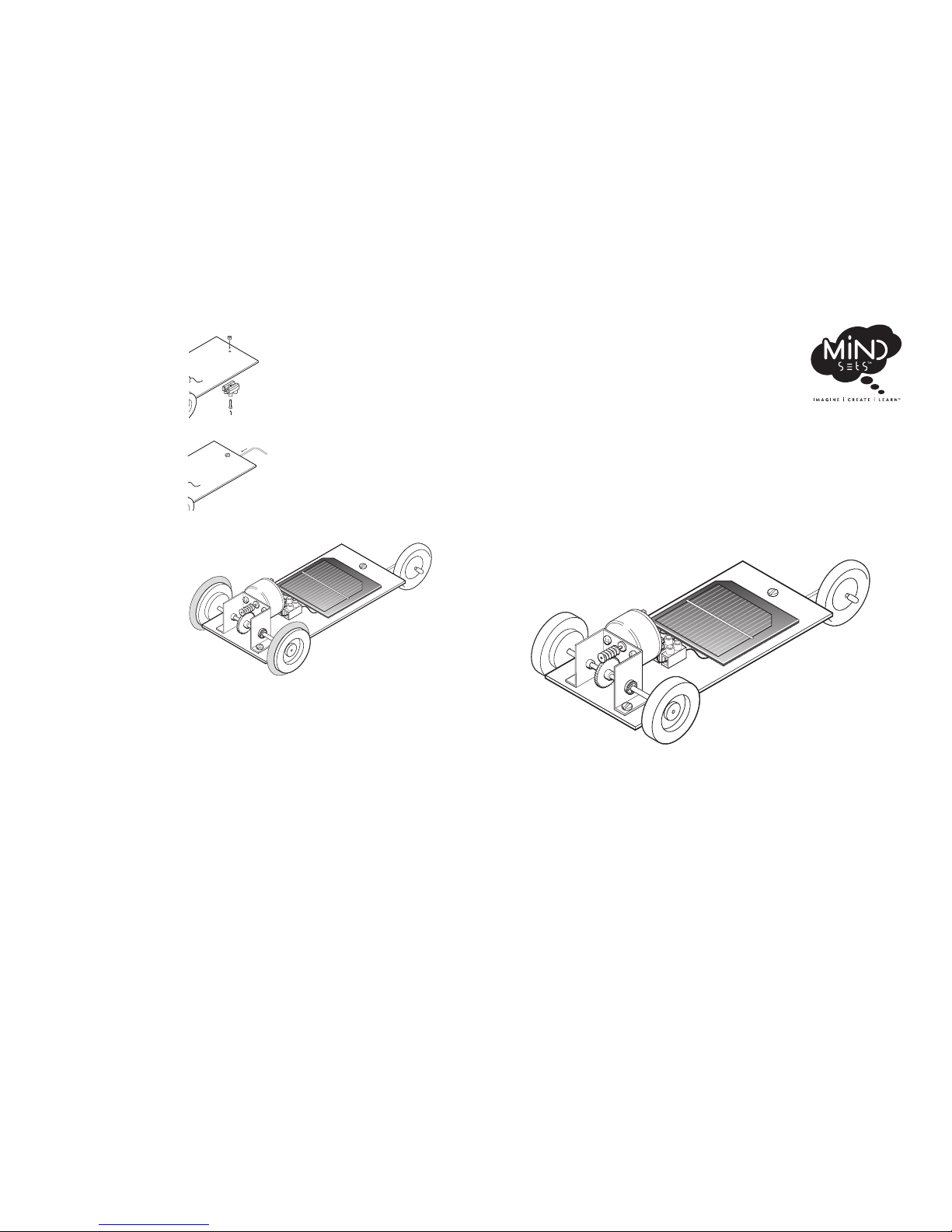
5. Fix the larger connecting
block under the front of the
chassis by inserting a screw
through the centre hole and
attaching a nut to the other
end.
6. Fix the front axle wire into
the connecting block as
shown.
7. Fit the wooden wheel onto
the front axle, then push the
small plastic sleeve over the
end of the axle to prevent
the wheel coming off.
8. Fit a rubber tyre O-ring to
each of the back wheels. The
solar buggy is now ready for
use. It should work in bright
sunlight or under bright
artificial light.
For more information please contact:
Mindsets (UK) Limited
Tel: 01992 716052
Fax: 01992 719474
Web: www.mindsetsonline.co.uk
Page 2
2
SOLAR POWER PROJECT PACK
INTRODUCTION
Solar energy has been an important form of power for many years
but it is only recently, with the development of efficient low cost
solar panels, that its use has become more widespread. Today’s
applications of solar power range from spacecraft and unmanned
aircraft to street lights, parking meters and calculators. The monocrystalline solar panel supplied in this pack (code: EL1 006)
provides opportunities for a wide range of interesting investigations
and project applications, particularly when combined with the
amazing storage potential of a supercapacitor (code: EC4 050), also
supplied in the pack. This booklet highlights some of these
investigations and applications.
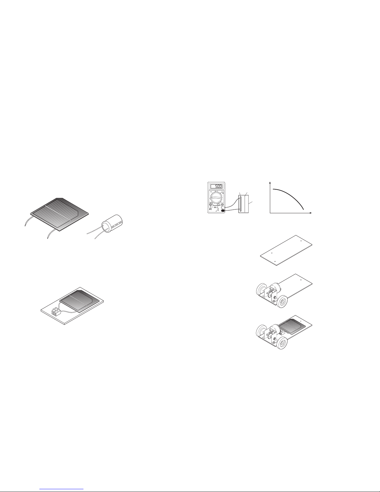
roticapacrepuSlenap raloS
Output: 4.5 volt @ 100mA 10 Farad, 2.5V
Code: EL1 006 Code: EC4 050
CONNECTING THE SOLAR PANEL
For temporary connections to the solar panel it is suggested that a
terminal block (supplied) or terminal posts (available separately) be
used. For added protection the solar panel may be stuck to a rigid
base using double sided sticky pads.
LIGHT SOURCES
The output from the solar panel depends on the light level; the
brighter the light, the greater the output. Bright sunlight or
powerful halogen lights will produce the best output from the solar
panel. The rechargeable cordless spotlight available from Teaching
Resources (code: TOO 073) is an ideal artificial light source. A
standard 60 watt or 100 watt electric lamp is also a good light
source but care should be taken due to the heat of these bulbs.
blue
(-ve)
red
(+ve)
(-ve)
(+ve)
7
Investigating Glow-in-the-Dark Materials
Using a solar panel connected to a multimeter it is possible to
investigate light emission from glow in the dark materials. For
example, a piece of glow in the dark film (code: SM1 016) may be
‘charged up’ under a bright light then placed in front of the solar
panel in a light-proof box. By observing meter readings it is then
possible to plot a graph showing how the light emission from the
material varies with time. Another investigation involves the use
of different light sources to energise the glow in the dark material.
Which types of light are most or least effective?
APPENDIX 1 - MAKING THE SOLAR BUGGY
1. Punch or drill two holes in
the chassis plate for the solar
gearbox and one hole for the
front axle assembly.
2. Fix the gearbox to the
chassis using screws and
nuts and press a plastic
wheel onto each end of the
axle.
3. Fix the double connecting
block and the solar panel to
the chassis using doublesided sticky pads.
4. Secure the wires from the
gearbox and solar panel in
the connecting block.
OFF
V
600
200
A
200µ
20m
V
2000µ
200m
10
600
200
20
2000m
200m
2000k
200k
20k
2000
200
Ω
hFE
10A DC
VΩmA
COM
TEACHING
RESOURCES
DT-830B
NPN PNP
E
B
C
E
E
C
B
E
solar
panel
glow in the
dark film
lightproof
box
output
time
Page 3
3
POWERING A COMPONENT USING THE SOLAR PANEL
In the right light conditions the output from the solar panel is
sufficient to power components such as LEDs, small motors and
LCD displays. For components with a positive and negative
terminal, the red wire from the solar panel must connect to the
positive terminal.
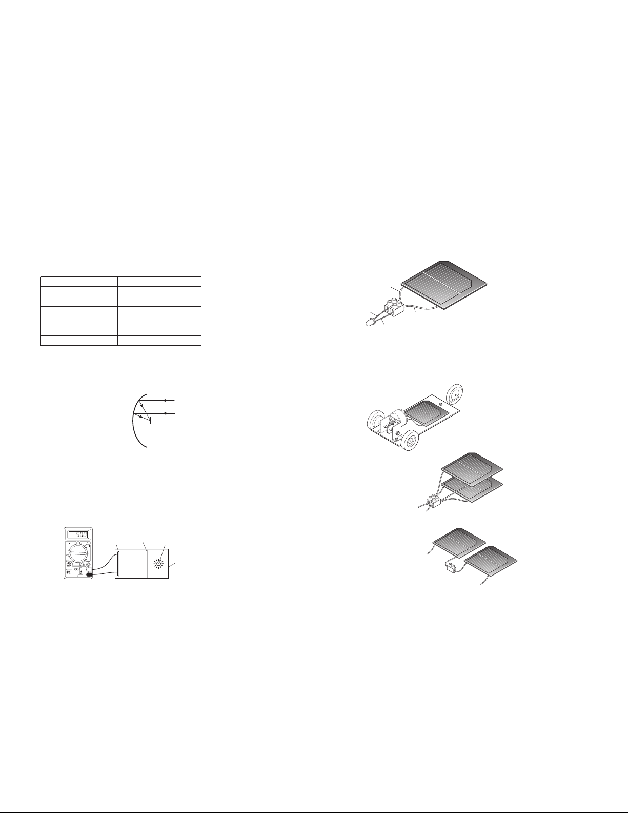
The best type of motor to use with the solar panel is a solar motor
because this type will run with a small current. However, the
MM10, MM12, MM18 and the economy gearboxes will also work
directly from a single solar panel. The illustration below shows a
solar powered buggy that has a solar motorised gearbox.
Instructions explaining how to make the buggy are included at the
end of this pack.
blue
wire
cathode
red
wire
anode
If a larger motor is required, two
or more solar panels may be
connected in parallel to
produce a higher current.
For components that require a
higher voltage, two or more
solar panels may be connected
in series.
6
Investigating the Output of the Solar Panel
Connect a multimeter to the solar panel and adjust it to the 200mV
setting. The meter will display the voltage produced. Try covering
the panel with a hand and observe the drop in voltage. How does
the voltage change in different light conditions? Write your
findings in the table below. In brighter conditions you will need to
switch the meter to the 20V setting.
)Vm( tuptuOnoitidnoC thgiL
Bright sunlight
Overcast daylight
Indoor electric light
Indoor fluorescent light
Halogen spotlight
Battery powered torch
Reflectors can be used to increase the amount of light falling on the
solar cell. Mirror card (code: GS6 007) or mirror polystyrene (code:
CS6 004P) are ideal materials for making reflectors - kitchen foil is
an alternative. Different shapes and different positions of the
reflector can be explored; the multimeter will give a clear
indication of which ones work best.
Examination of reflectors in
torches and other lights may be
helpful here. Many such
reflectors have a parabolic
shape, which focuses light
towards a single point.
Investigating the Spectral Response of the Solar Panel
Intensity of the light is one factor that determines the output of the
solar panel, but it is not the only factor. The wavelength of the
light also makes a difference. This can be investigated using, for
example, coloured LEDs or coloured filters. Many types of LED are
available, including UV and infrared, but it is important to select
LEDs of a similar intensity for the investigation. To avoid
inaccuracies due to changes in the background light, it is suggested
that a ‘black box’ be made to house the solar panel and light
source.
Focal point
Parabolic reflector
OFF
V
600
200
A
200µ
20m
V
2000µ
200m
10
600
200
20
2000m
200m
2000k
200k
20k
2000
200
Ω
hFE
10A DC
VΩmA
COM
TEACHING
RESOURCES
DT-830B
NPN PNP
E
B
C
E
E
C
B
E
solar
panel
light
source
coloured
filter
light
proof
box
Page 4
4
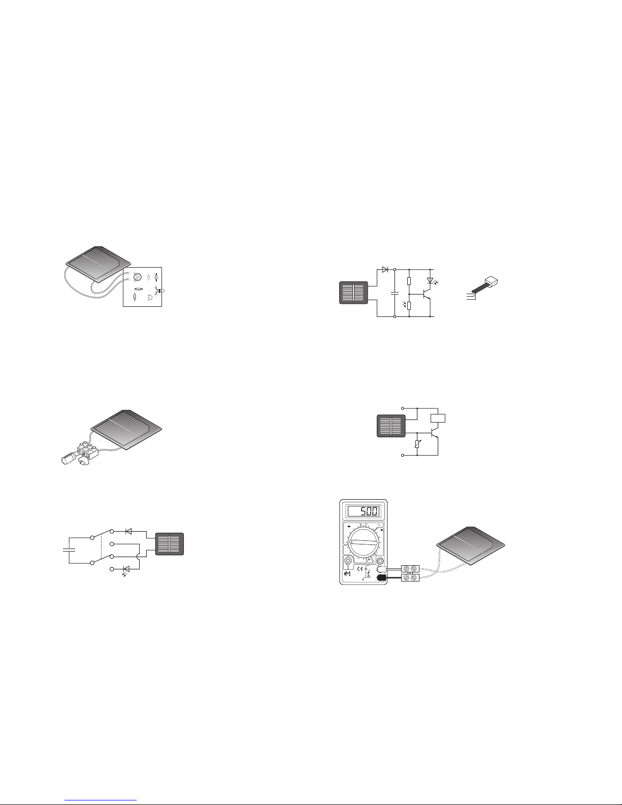
As well as powering single components the solar panel can also be
used to power complete circuits, such as the transistor project
board (code: ELE 062a) or an LCD clock.
USING A SUPERCAPACITOR WITH THE SOLAR PANEL
A supercapacitor looks much the same as a regular electrolytic
capacitor but is able to store a much higher charge. Unlike regular
capacitors, which use conductive foils and a dry separator, the
supercapacitor has special electrodes and electrolyte. The type
supplied has a 10 Farad capacitance - more than 2000 times greater
than a 4700µF capacitor!
A fully charged supercapacitor will power an electric motor for a
couple of minutes or a small LED for several hours. One way to
charge a supercapacitor is to connect it to a battery for about 10
seconds (or longer for a full charge). Alternatively it can be ‘tricklecharged’ using a solar panel, as shown in the illustration below.
Note the use of a diode to prevent current ‘leakage’ from the
capacitor.
Supercapacitors cannot be overcharged - when they are full they
stop accepting charge. Charging time will depend on the level of
light, but can be reduced by connecting additional solar panels.
Once charged, the supercapacitor can be disconnected from the
solar panel and is ready for use. The addition of a double pole
double throw (DPDT) switch makes it easy to switch between
charging mode and running mode.
INPUT
SENSOR
D1
R3
OUTPUT
C
B
E
R2
OUTPUTPROCESSINPUT
R1
TRANSISTOR PROJECT BRD
+
diode
+
LED
solar
panel
capacitor
DPDT
switch
WARNING
Do not charge the
supercapacitor beyond 3V.
5
Automatic switching circuits are more complex. One solution
makes use of a light dependent resistor and a transistor, as shown
below. In good light conditions the transistor is switched off and
the solar panel charges the supercapacitor. When the light level
drops the supercapacitor provides the power. The transistor
switches on and the LED lights up.
The supercapacitor provides exciting opportunities in the context
of product design and rechargeable products. Possibilities include
the design of robots, buggies, torches, warning devices, motorised
tools, toys, etc.
USING THE SOLAR PANEL AS A SENSOR
The solar panel can be used in light sensing circuits as an
alternative to a light dependent resistor. This is useful where highpower devices need to be activated by light. The panel is
connected to a transistor such as a BCX38B, as shown in the
diagram below.
INVESTIGATIONS USING THE SOLAR PANEL
There are several interesting experiments that can be undertaken
quickly and easily with the solar panel. Several of these require
measurement using a multimeter (code: MET 001).
+
+
b
e
c
+
output
+V
0V
10k
OFF
V
600
200
A
200µ
20m
V
2000µ
200m
10
600
200
20
2000m
200m
2000k
200k
20k
2000
200
Ω
hFE
10A DC
VΩmA
COM
600V max
CAT II
600V
0.2A max fused
10A max
unfused
TEACHING
RESOURCES
DT-830B
NPN PNP
E
B
C
E
E
C
B
E
collector (c)
base (b)
emitter (e)
BC548 transistor
 Loading...