

Page 1
What is PCF8574-Nx
PCF8574-Nx is a kit to interface 8-bit digital IO chip to NXT. It contains
all the basic parts needed along with general-purpose prototyping area on
the PCB. This kit can be used to design any custom sensor or IO device with
NXT. Following sections provide basic assembly instructions for this Kit.
PCF8574-Nx Feature List
• Uses NXT compatible I2C protocol for communications.
• All needed basic components included.
• Position for second NXT compatible socket that lets you connect the
multiple boards to same sensor port.
Connections
Can be connected to any four ports of NXT
by using standard NXT cables.
PCF8574-Nx V1.1User Guide
Tools you will need
All the electronic components needed for assembly are included. To
assemble these components, you will need a soldering iron, solder, pliers, and
wire cutter to cut the resistor and capacitor wires.
Assembly
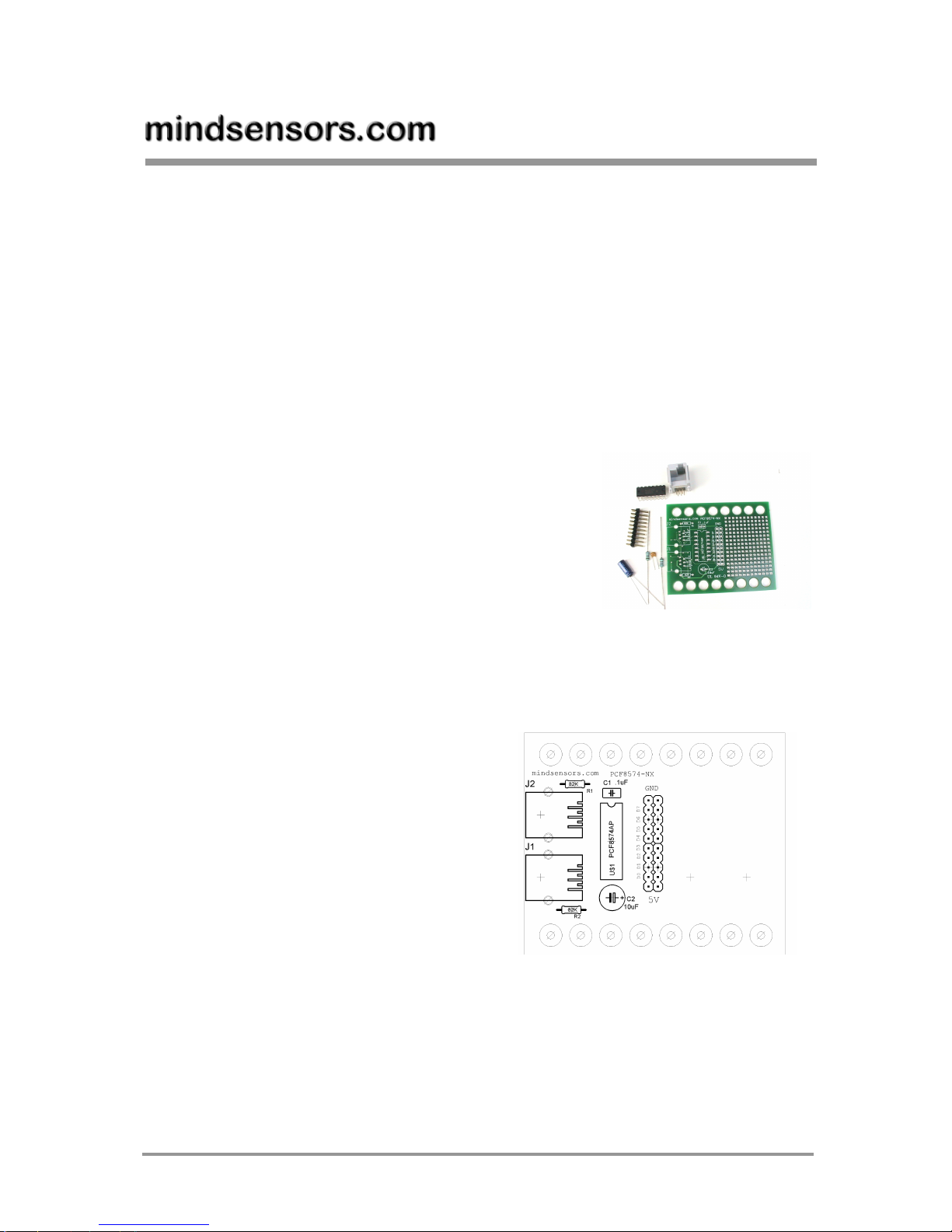
Connect all the components as
shown on the PCB silkscreen. You
can connect NXT style socket
either to J1 or J2. You can use
the second jack to daisy chain the
boards. That way, you can connect
more than one sensor to single
NXT port. If you plan to do that,
ensure to use resistors R1 and R2
only on one board.
Copyright © 2007 mindsensors.com 1/5
Page 2
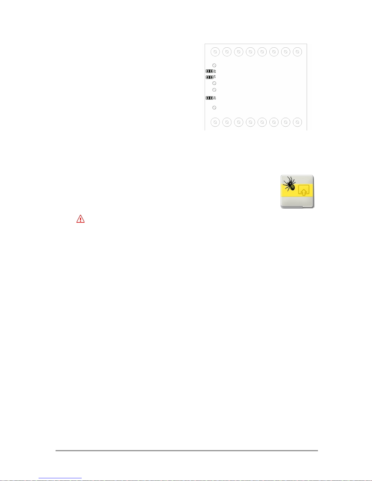
Also ensure to select the correct
address by shorting the PCB
jumpers A0 A1 A2 at the bottom
of the board either on the lower
side (logic low) or the upper side
(logic Hi). e.g. Shorting A0, A1, A2
all to logic low will set the I2C
address of 0x40. For more details
on address selection refer to the
PCF8574 datasheets.
Programming Techniques for reading in I2C mode
NXT-G:
You can use the PCF8574-Nx with PCF8574-NX sensor block.
You can download this block from ‘Download’ section of
mindsensors.com website. (This requires Dynamic block
update patch installed on your NXT-G).
NOTE
Ensure to use LEGO firmware 1.05 on NXT while using NXT-G blocks.
RobotC:
You can use example program in C and robotC compiler to use PCF8574-Nx
on your NXT robot.
NBC:
You can use example program in NBC and NBC compiler to use PCF8574-Nx
on your NXT robot.
Robolab:
You can use example program and drivers Vi in Robolab 2.9 compiler to use
PCF8574-Nx on your NXT robot.
Copyright © 2007 mindsensors.com 2/5
Page 3

Figure 1 PCB Silk Screen
Copyright © 2007 mindsensors.com 3/5
Figure 2 Schematic Diagram
Page 4

Frequently Asked Questions (FAQ)
How do I identify a resistor?
Each color band on a resistor is associated with a number as follows:
Color Number
Black 0
Brown 1
Red 2
Orange 3
Yellow 4
Green 5
Blue 6
Purple 7
Gray 8
White 9
On a 4-band resistor, third band is the
multiplier band. The adjacent picture
shows how to read the bands on the resistor.
How do I read the pins on an IC?
Pin no. 1 on the IC is usually marked with an engraved dot. Hold the IC such
that the pins are facing away from you, and number the pins anticlockwise,
beginning at pin with the dot.
How do I identify a diode and it’s direction?
Diodes normally have glassy casing, and
are marked with a band on one end.
The band end is the ‘cathode’ and the
other end is the ‘anode’. Within the
diode, the current flows from anode to
cathode.
On the Schematic, the cathode end is represented as the tip of the arrow.
How do I identify LED polarity?
Hold the LED against the light, and when you
look at the metal elements inside, you will notice
that one half is bigger than the other and looks
like a flag, this is the ‘cathode’ (or negative) end
of the LED.
Copyright © 2007 mindsensors.com 4/5
Page 5

How do I connect the LEDs?
Hold your LED against the light and inside, the cathode end inside (as shown
in above picture) should match up with the flat side on PC board marking
(silkscreen).
How do I distinguish C1 and C2?
C2 is the larger capacitor, whereas C1 is the smaller capacitor.
Assembly tips
The pins can be bent suitably to attach on the PCB.
While assembling, solder the components with many pins first, (such as
IC) and then solder components with lesser number of pins. Finally solder
the connecting wires.
Further reading
How to read a diode:
http://www.americanmicrosemi.com/tutorials/diode.htm
How to read resistor
http://www.aikenamps.com/ResistorColorCode.htm
http://www.eidusa.com/Electronics_Resistors.htm
Tips on soldering
http://library.thinkquest.org/2784/inspire/soldering_hints.html
How to read schematics
http://www.learn-c.com/schemat.htm
Books
Beginners Guide to Reading Schematics, by Robert J. Traister, Anna L. Lisk.
Warnings
Wear Eye protection gear while assembling the kit.
Soldering iron is hot, and be careful while handling it.
While soldering, do not heat components any longer than 10 seconds, it
The fumes generated while soldering may be harmful. Work in a well
The soldering metal may contain lead. So wash your hands thoroughly
When fully assembled, test with a 9 volts non-RCX power before
Improper assembly may damage kit components.
may damage the components.
ventilated area and do not breathe the fumes.
with soap after handling such materials.
attaching to RCX.
Copyright © 2007 mindsensors.com 5/5
 Loading...