

Page 1
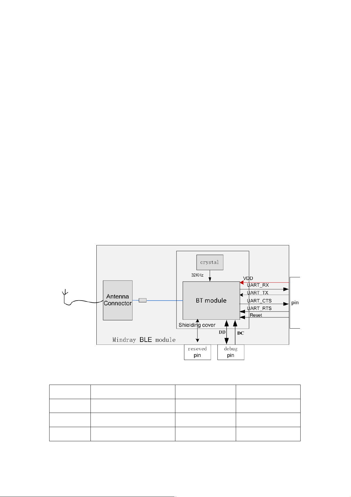
1.1 General
No. Pin name
Type
description
1 to 8
NC / No use
9
DC I Debug clock
10 DD O Debug data
Decription
Panlink module consists of a BT module, crystal and antenna connector. This module can
change UART signal to wireless signal using Bluetooth low energy technology. This module uses
external antenna via a Antenna connector.
Panlink communication type is piconet, which means Panlink transfers data to another
Panklink(one is master, the other one is salve).
When transfering data from master to slave, data was given to master by UART. Then
master panlink controls signal, frames, radiation power and transmits them via the antenna to slave
panlink. Slave panlink get RF signal via the antenna and resolve it to data.
When transfering data from slave to master, data was given to master by UART. Then slave
panlink controls signal, frames, radiation power and transmits them via the antenna to master
panlink. Master panlink get RF signal via the antenna and resolve it to data.
1.2 Block diagram
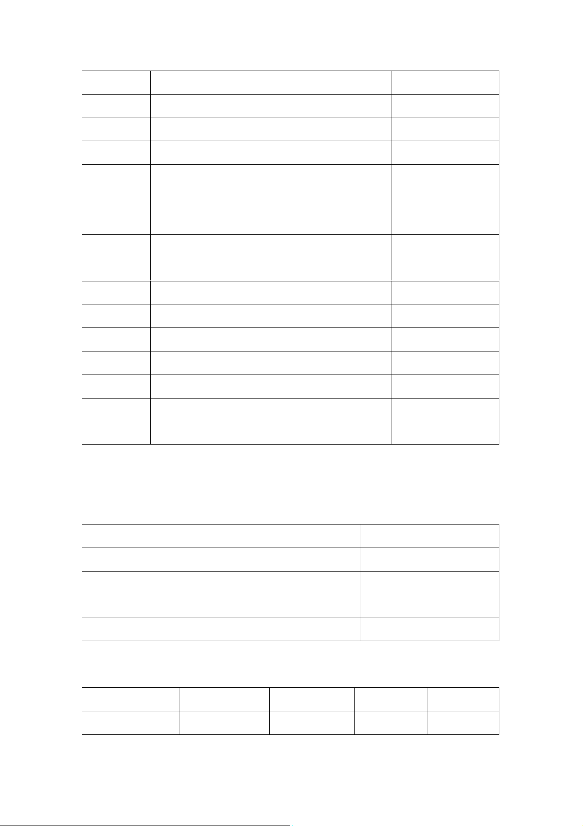
1.3 Interface and pin definition
Page 2
11 SLEEP_OUT/P3_0
O
Wakeup out
12 VDD
Power
Power in
13 GND
Power
ground
14 Reset
RSTN
Reset in
15 Wake/P0_3
I
Wake up input
16 UART_RXD0
I
Uart in, baud rate is
115200
17 UART_TXD0
O
Uart out, baud rate is
115200
18 nCS1/CTSn1/P1_2
I/O Reserved
19 CLK1/RTSn1/P1_3
I/O Reserved
20 MOSI1/TXD1/P1_1
I/O Reserved
21 MISO1/RXD1/P1_0
I/O Reserved
22 CD O Module detect pin
23 RF Connector
RF Connect to external
antenna
Item
VALUE
UNIT
Supply voltage range
-0.3 to 3.9
V
Voltage range to any of digital
pins
-0.3 to VDD + 0.3, <3.9
V
Storage temperature range
-40 to +85
℃
Item
MIN
NOM
MAX
UNIT
Supply voltage
2.0
3.6 V
1.4 Operation specification
ABSOLUTE MAXIMUM RATINGS
Over operating room temperature range (unless otherwise noted)
RECOMMENDED OPERATING CONDITIONS
Over operating room temperature range (unless otherwise noted)
Page 3
range
Operational
temperature range
-20
+70
℃
1.5 Wireless specifications
Protocol:Bluetooth low energy 4.0
Modulation mode:GFSK
Operating frequency:2402 ~ 2480MHz(40 channels)
Channel spacing:2MHz
Wireless baud rate(data rate): 1Mbps
Output power (transfer power): ≤2.5mW
Data security : 128bit AES
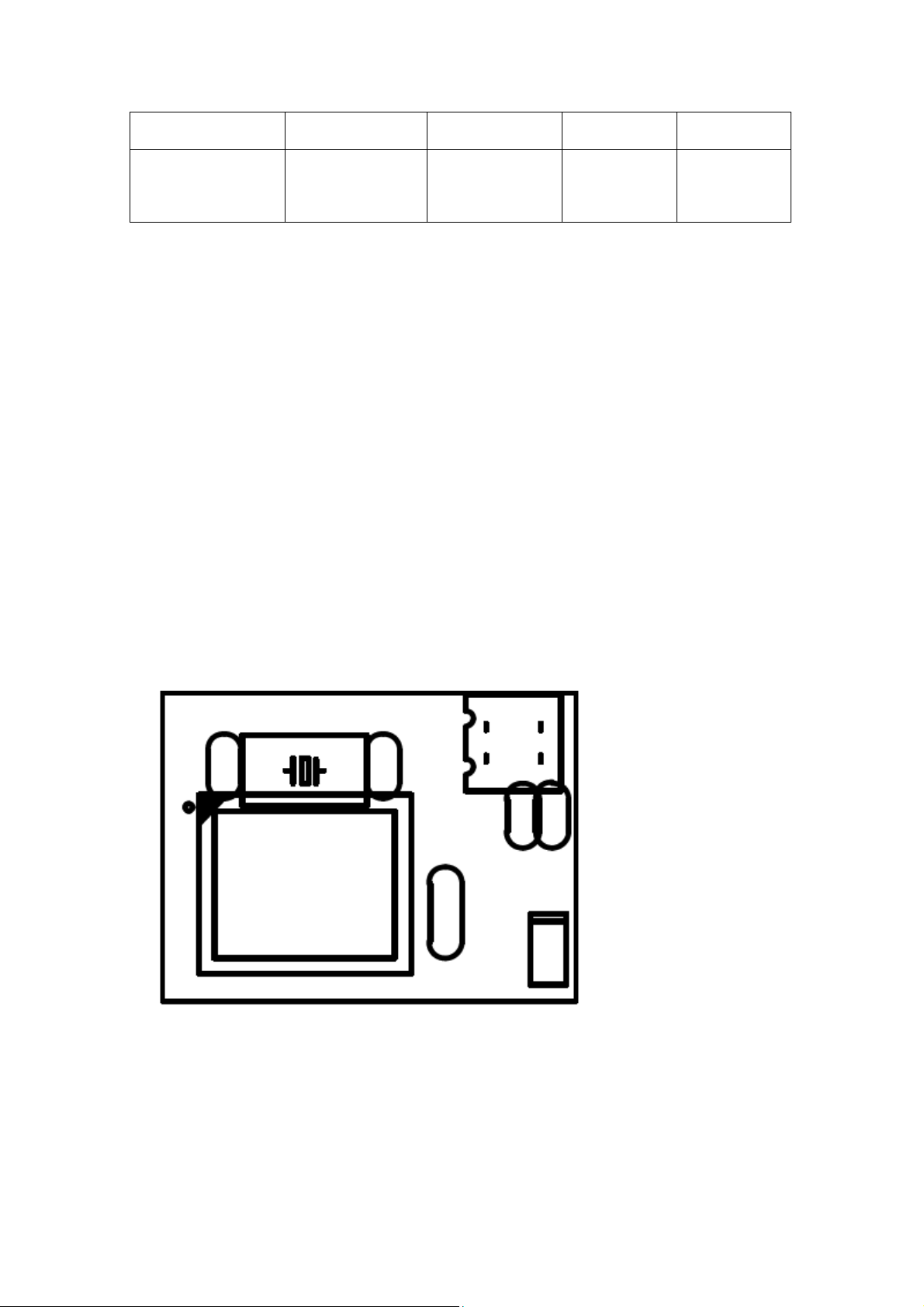
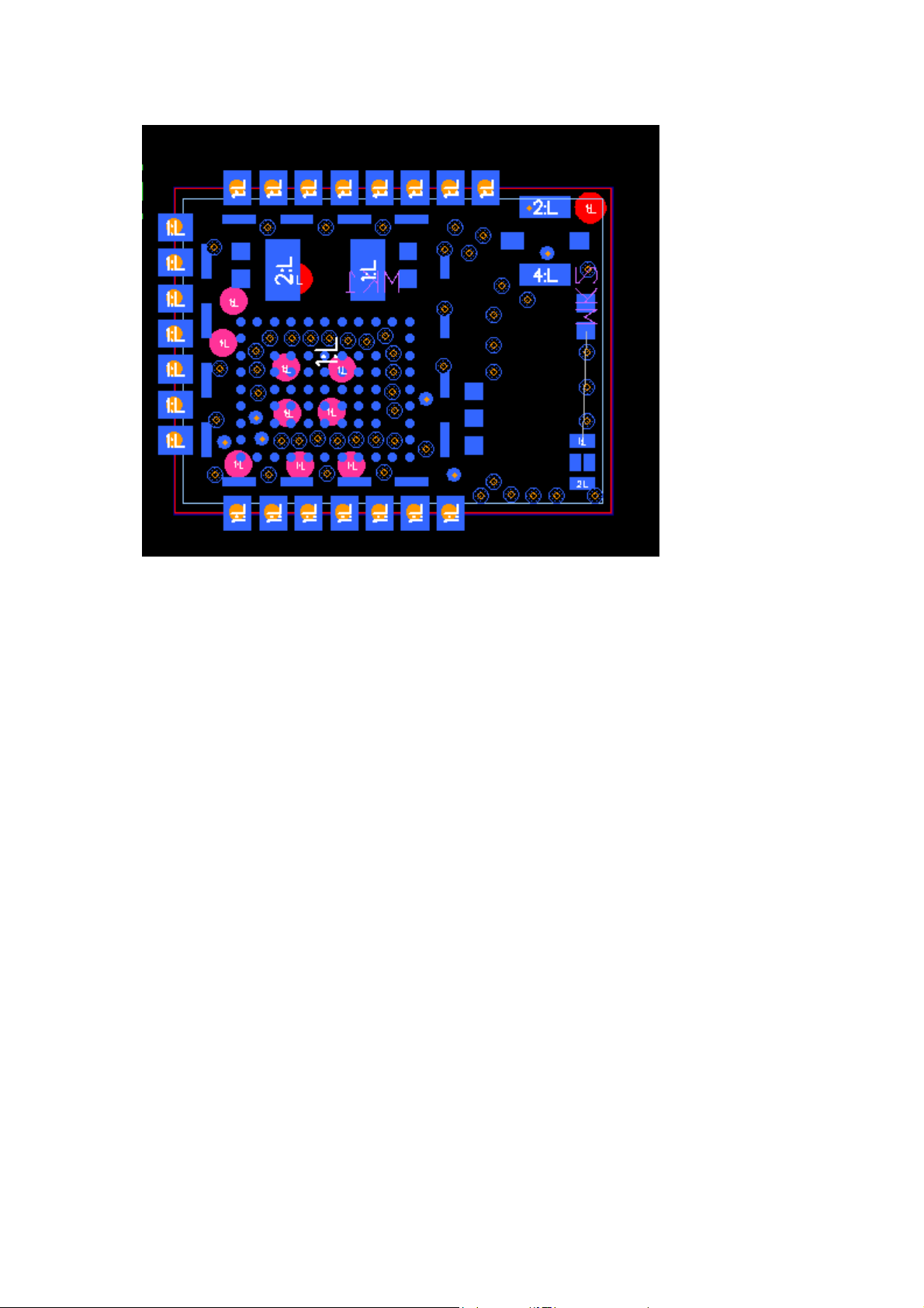
1.6 Mechanical and package description
Dimension is 9.6mm*12.9mm*2.3mm, and package type is SMT.
Page 4
This device and its antenna must not be located or operating in conjunction with any other antenna
and transmitter.
This device complies with part 15 of the FCC rules. Operation is subject to the following two
conditions: (1) this device may not cause harmful interference, and (2) this device must accept any
interference received, including interference that may cause undesired operation.
Changes or modifications not expressly approved by the party responsible for compliance could
void the user’s authority to operate the equipment.
NOTE: This equipment has been tested and found to comply with the limits for a Class B digital
device, pursuant to part 15 of the FCC Rules.
These limits are designed to provide reasonable protection against harmful interference in a
residential installation. This equipment generates uses and can radiate radio frequency energy and,
if not installed and used in accordance with the instructions, may cause harmful interference to
radio communications.
However, there is no guarantee that interference will not occur in a particular installation. If this
equipment does cause harmful interference to radio or television reception, which can be
determined by turning the equipment off and on, the user is encouraged to try to correct the
interference by one or more of the following measures:
- Reorient or relocate the receiving antenna.
- Increase the separation between the equipment and receiver.
-Connect the equipment into an outlet on a circuit different from that to which the receiver is
Page 5

connected.
-Consult the dealer or an experienced radio/TV technician for help Important announcement
LABEL OF THE END PRODUCT:
The final end product must be labeled in a visible area with the following" Contains FCC
ID: ZLZTDBTFE ". The FCC part 15.19 statement below has to also be available on the
label: This device complies with Part 15 of FCC rules. Operation is subject to the
following two conditions: (1) this device may not cause harmful interference and (2) this
device must accept any interference received, including interference that may cause
undesired operation.
To comply with FCC regulations limiting both maximum RF output power and human exposure to
RF radiation, the maximum antenna gain including cable loss in a mobile-only exposure condition
must not exceed -1dBi.
A user manual with the end product must clearly indicate the operating requirements and conditions
that must be observed to ensure compliance with current FCC RF exposure guidelines.
The end product with an embedded Pan link Module may also need to pass the FCC Part 15
unintentional emission testing requirements and be properly authorized per FCC Part 15.
a. The module is limited to OEM installation ONLY;
b. The OEM integrators is responsible for ensuring that end-user has no manual instructions to
remove or install module;
c. The module is limited to installation in mobile or fixed application
d. The separate approval is required for all other operating configurations, including portable
configuration with respect to Part 2.1093 and different antenna configurations;
e. The host manufacturer is responsible for ensuring that after the module is installed and
operational the host continues to be compliant with the Part 15B unintentional radiator requirements.
 Loading...