


NANOMIND 110
USER MANUAL
Highlights
- MindRacer in nano size frame, running MindPX & PX4 flight stack
-
heavy lifter, maximum take-off weight up to 80 g
-
5~7 minutes flight time
-
full modularized, stackable, soldering-free assemble
-
stackable style WEP expansion interface
-
DroneCode compliant sockets
Website
www.mindpx.net
Contact
support@mindpx.net
V1.2
AirMind Inc.,
Ta bl e o f Co nt en t
Note This manual can be used with NanoMind 110 BNF/RTF Kit series, and NanoMind 110 Tiny-whoop BNF/RTF
series.
Important
Coreless DC motors have lifetime of about 10 hours of total flights. To avoid fast retardation it is
suggested to take 5~8 minutes break between flights.
Physical 3
Quick Installation 4
Power On/Off 6
Charging battery 6
RC Pairing 7
Arm/Disarm 7
Select Flight Mode 8
Flight Black Box - Using a SD Card 9
FPV Camera and Display (for tiny-whoop) 9
Connect to Ground Station 10
Calibrate New Remote Controller in QGC 11
Color LED Indicator 12
Support 13
Where to buy 13
Page 2
!

Physical
Page 3
NanoMind 110
WheelBase
110mm diagonal
Weight
35g (w/o battery)
Propellers
55mm
Flight controller / Processor
MindRacer v1.2 / STM32F427
IMU / Redundancy
10DOF / N
Motor
Coreless DC motor
ESC
N/A
Video transmitter (tiny-whoop only)
5.8GHz 40CH
Camera (tiny-whoop only)
600TVL PAL/NTSC
GPS support (optional)
Y
Optical Flow support (optional)
Y
Lidar support (optional)
N
Battery
300mah/650mah
Quick Installation
NanoMind 110mm nano-size quad comes within bind-n-fly package. All components you need to install
before flying simply are:
1.
propellers
2.
FPV camera (NanoMind tiny-whoop only)
3.
battery
Fig. 1 Quick installation
- Install the propellers
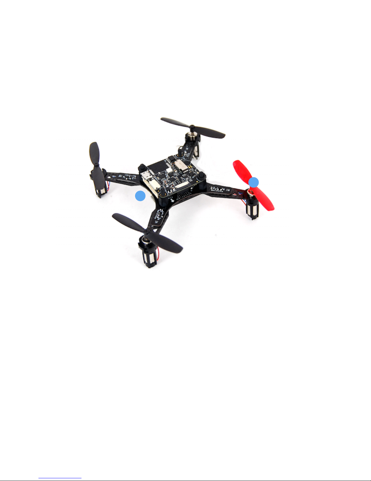
The propellers need to be installed in specified order as in Fig. 2. It is important to notice that installing
into wrong position will make the copter overturned and may cause serious harm.
Find the head of direction mark (‘Front’) on the frame, and align with the direction of head shows in Fig.2.
The 2 pull propellers (marked with ‘B’) should be installed on motor 1 & 2 (clockwise - cw), while the 2
push propellers (marked with ‘A’) should be installed on motor 3 & 4 (counter clockwise - ccw).
Page 4
2
Propeller
Battery

Fig. 2 Install propellers
- Install FPV camera (for tiny-whoop model only)
Other models can skip this step.
Mount the FPV camera on the front 2 hexagon studs as shown in Fig. 3. Connect FPV camera power cable
to the 5V output socket on the bottom frame.
Fig. 3 Install FPV camera
Page 5
Direction of head
2
3
CW motor
CCW motor
CW motor
CCW motor
Propeller ‘A’ (push)
Propeller ‘B’ (pull)
Propeller ‘B’ (pull)
Propeller ‘A’ (push)
Front
1
5V output socket
Mount FPV camera here
Direction of head

- Install the battery
The battery should be mounted on the bottom of drone. The bottom surface of battery and the top
surface of drone are all attached with nylon fastener tape by default. Place the battery on the position of
the nylon fastener tape, and give light push on the battery to make sure it is fastened solidly. Fasten the
pre-installed nylon belt around the battery to enhance the mount.
After mounted plug the battery connect to the power head on the tail of drone.
Power On/Off
Once the battery is connected to the power head of drone, all parts will be powered on. The main LED on
flight controller will turn to breathing blue and the drone is now ready for command.
Disconnect the battery when you finished a flight.
Charging battery
Battery can be charged through the built-in USB charger. Connect the USB port (type C) to any standard
5V output power source (like computer USB ports, power bank, etc.) and the charging will start. The
orange LED indicator is constantly on during charging. After charging is completed, the orange LED will
be out and the green LED will be on.
The power supply to flight controller and other components on the frame will be cut off once the
charging port is connected to valid power source.
Fig. 4 USB charger
Note Be careful not to mix the charger USB port with the USB port on flight controller. Charger USB port
is on the bottom plane of the frame (as in Fig. 4).
Page 6
USB charger port

RC Pairing
The remote controller needs to be paired with the drone before it can control the drone to fly. For RTF
option, the remote controller comes together with the drone is already been paired with copter by
default so you can skip this step.
Fig. 5 RC pairing
However with BNF option or for other cases you may need to pair/re-pair and do some setting with the
remote controller. To do that, !
1) remove the MindRacer flight controller on the top and let the bottom frame exposed.
2) Find the ‘bind’ button on bottom frame (take FrSky receiver option as an example as in Fig. 5) and use
this button to pair with your remote controller.
Note that some receiver does not need a bind button to do pairing so you can skip this step. Refer to
below’s list of pairing instructions for details.
Please follow the instructions from remote controller vendor to complete the paring procedure. You can
find detailed information about the paring procedure in following list of compatible remote controller
models that may come with NanoMind.
FrSky Taranis X9D/PLUS (S.Bus) pairing and setting instructions
RadioLink AT9/S (S.BUS) pairing and setting instructions
Spectrum DX series (DSM) pairing instructions
FlySky AFHDS2A series (PPM) pairing instructions
Arm/Disarm
Warning: before arm, please make sure no obstacle can be occluded with drone’s spinning propeller.
Note: by default MR210 uses mode 2 (throttle on left) remote controller. All guides below will be based
on left throttle pattern.
Page 7
‘Bind’ button
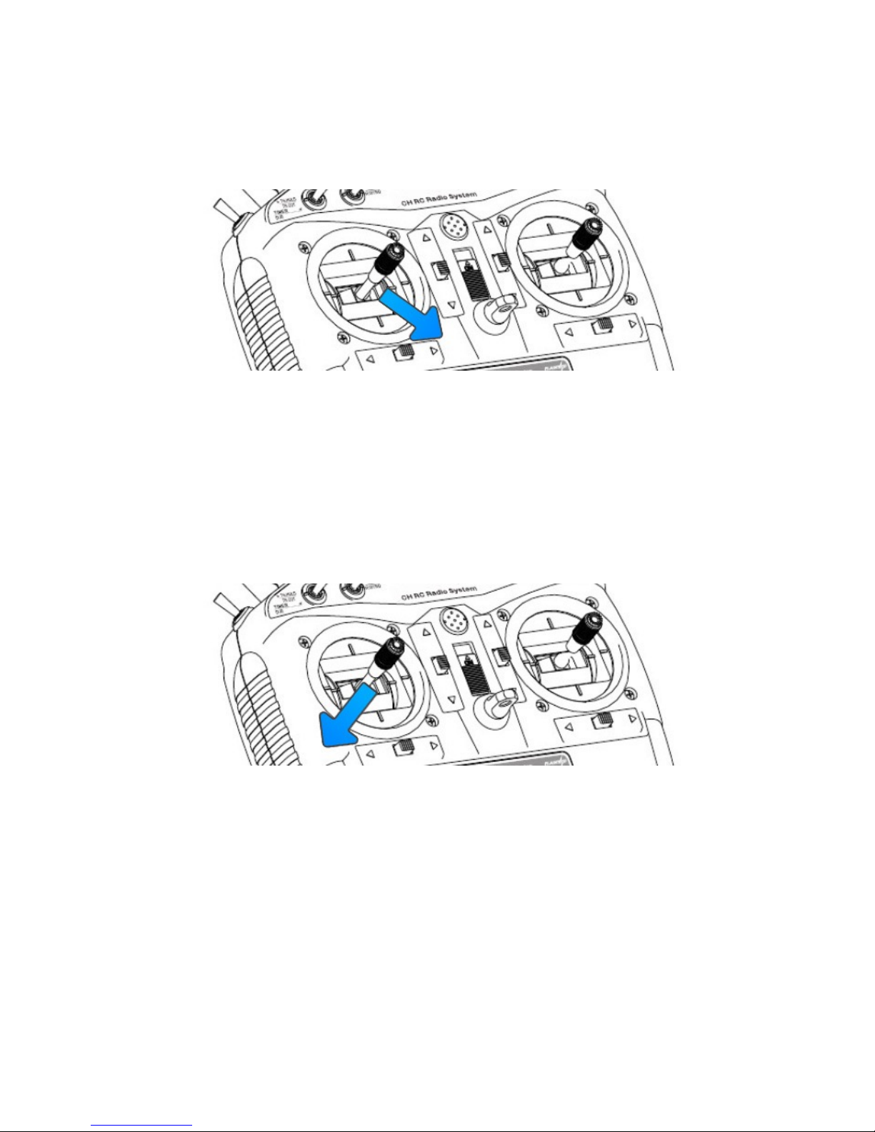
After the remote controller is powered on and paired, lower the throttle stick to the low-right corner for a
few seconds. The propeller will start to spin at a minimum speed. The drone is then in armed state and
ready to take off.
Fig. 6 Arming
To disarm, lower the throttle stick to the low-left corner for a few seconds, the propellers will stop
spinning.
Fig. 7 Disarming
Select Flight Mode
Flight modes is pre-set on remote controller as in Fig.8. By default 4 flight modes are configurable
through remote controller: manual, assist/altitude control, assit/position control, and acro mode.
The modes can be chosen by switches in the remote controller (use WFLY/7 remote controller as an
example) as in Fig. 6.
Page 8

Fig. 8 select flight modes
For beginners, manual mode is a good start point, as the drone will auto stabilize its attitude during the
flight which makes it easier for pilots to control. When pilots eventually get more and more experienced
then can switch to acro mode for a real racing.
Switch layout on different remote controllers are usually different. You can change the layout of mode
switches or define more flight modes through QGroundControl. Please refer to MindRacer User Guide
document for details.
Flight Black Box - Using a SD Card
MindRacer has a micro SD (TF) card slot. MindRacer will record flight data into the SD card. It is important
for reproducing flight course either for training or maintenance purpose. So it is strongly recommended
that user inserting a SD card before take off.
The SD card must be formatted with FAT32.
FPV Camera and Display (for tiny-whoop)
FPV camera video transmitter needs to be paired with receiver before flight. The channels of transmitter is
set by a push button on the transmitter, with LED indicator showing the current selected channel and
band. The default channel setting for transmitter is B8(5945MHz).
By default you do not need to adjust any of the setting as during manufacture the default display kit has
been paired with the transmitter. In case you want to change the setting or use a different receiver than
default display kit, you need to access the the switch group on the video transmitter board.
Note during a racing match, you need to make sure your video transmitter channel setting does not
interfere with others.
The detailed frequency and channels settings are listed below (Fig. 9).
Page 9
assist/alt-ctrl
assist/pos-ctrl
assist
manual
acro
return-to-land
mission

Fig. 9 frequency and channel settings
Pilots use FPV goggles to receive video streams from drone’s camera. The goggles needs to be correctly
setup before it can receive video. Please check and follow goggles vendor’s guide to set it up. By default
the goggles needs to be tuned to the same frequency of MR210’s transmitter (5945MHz) to work
properly.
Change Frequency Group and channel
Use the 2 buttons on the top of camera to adjust group and channel.
Long press on the front button for 2 seconds switches between PAL/NTSC. Short click flip video images.
Long press on the back button for 2 seconds change groups. Short click change channels.
Connect to Ground Station
As a professional flight controller, MindRacer has hundreds of parameters that user can tune. Using
QGroundControl software from computer is the best way to carefully adjust these parameters.
QGroundControl is a free software that anyone can download and use it on the fly. It can be downloaded
from http://www.qgroundcontrol.org. Currently it can support all major PC OS platforms including
Windows, MacOS, Linux, etc. Select the right version for your OS.
To connect, launch QGroundControl on your PC (Fig. 10).
Page 10
CH1/5
CH2/6
CH3/7
CH4/8
Group A
5740MHz
5760MHz
5780MHz
5800MHz
5820MHz
5840MHz
5860MHz
5880MHz
Group B
5705MHz
5685MHz
5665MHz
5645MHz
5885MHz
5905MHz
5925MHz
5945MHz
Group C
5865MHz
5845MHz
5825MHz
5805MHz
5785MHz
5765MHz
5745MHz
5725MHz
Group D
5658MHz
5695MHz
5732MHz
5769MHz
5806MHz
5843MHz
5880MHz
5917MHz
Group E
5733MHz
5752MHZ
5771MHz
5790MHz
5809MHz
5828MHz
5847MHz
5866MHz
Group F
5362MHz
5399MHz
5436MHz
5473MHz
5510MHz
5547MHz
5584MHz
5621MHz

Fig. 10 Launch QGroundControl
Power OFF the drone first. Use a micro-USB cable to connect the ‘USB’ port of MindRacer to a PC USB
port. The MindRacer flight controller should be powered on. Wait for a few seconds until the flight
controllers main LED turns in to any stable color. The QGC will try to automatically connect to the flight
controller. After connected, the ground station will update its UI with drone’s status information.
Fig. 9 drone status information
Calibrate New Remote Controller in QGC
Page 11

In case you need to re-calibrate your remote controller, and configure the flight modes as in Fig. 5, you
can do this in QGC as depicted in Fig. 11.
Fig. 11 Re-calibrate remote controller and configure flight modes
Color LED Indicator
The main LED indicator is a tricolor LED and can show different status information with the combination of
different colors and blinks. The status information it indicates is listed below:
Fig. 12 LED indicator!
Page 12
LED color
meaning (status)
remark
Solid any color
Armed
Breathing any color
Standby
Amber
Low battery or Failsafe
(Return to home, etc)
Blue
GPS not locked
Green
GPS Locked
Fast Blink & Red
Arming error
Blink & Red
Other error
Transitional Green
Mode switch success

Support
Please visit www.mindpx.org for more information. If you have any technical issues related to our
products, please post on MindClub forum club.mindpx.net to ask for help, Or you can send email to
support@mindpx.net.
Where to buy
You can buy NanoMind or related accessories/spare parts at AirMind Store .
Page 13
 Loading...