


WaveRider
Operating Manual
www.MindPeak.com
Copyright 1997-2010 Jonathan Purcell
All Rights Reserved
MindPeak
(formerly WaveAccess)
40 Fourth St., Ste 211
Petaluma, CA 94952 USA
+707-780-9520 tel
+212-918-3428 fax
support@mindpeak.com
www.MindPeak.com

WaveRider Operating Manual
NOTICE:
The WaveRider is an experimental musical instrument intended for musical performance and
composition, education, and experimental computer interface applications. The WaveRider
is not intended for any type of medical use in either a diagnostic or therapeutic capacity. Any
individual or organization using the WaveRider in a medical capacity does so without the
endorsement of MindPeak/WaveAccess.
Copyright 1997-2004 Jonathan Purcell
All Rights Reserved
2

WaveRider Operating Manual
The only means of strengthening one's intellect is to
make up one's mind about nothing --to let the mind be
a thoroughfare for all thoughts. Not a select party.
JOHN KEATS 1795-1821
My mind to me a kingdom is,
Such present joys therein I find,
That it excels all other bliss
That earth affords or grows by kind.
SIR EDWARD DYER 1700?-1758
A breath from unfaith's halting place to faith,
This precious breath then do you cherish, for
Life's sum is but a breath from birth to death
For many days , my brain
Worked with a dim and undetermined sense
Of unknown modes of being
WILLIAM WORDSWORTH 1770-1850
It seems that things are more like me now,
I feel closer to what language can't reach.
and in the ponds broken off from the sky
my feeling sinks, as if standing on fishes.
RAINER MARIA RILKE 1875-1926 (trans. R. Bly)
Absence of occupation is not rest,
A mind quite vacant is a mind distress'd.
WILLIAM COWPER 1731-1800
From doubt to certainty is but a breath,
OMAR KHAYYAM
MOVING FORWARD
The deep parts of my life pour onward,
as if the river shores were opening out.
that I can see farther into paintings.
With my senses, as with birds, I climb
into the windy heaven, out of the oak,
3
Copyright 1997-2004 Jonathan Purcell
All Rights Reserved

WaveRider Operating Manual
Table of Contents
T
ABLE OF CONTENTS
THE SIGNIFICANCE OF BRAINWAVES AND CONSCIOUSNESS ........................................................... 6
HOW TO USE THIS MANUAL....................................................................................................................... 7
......................................................................................................................................... 4
QUICK START.................................................................................................................................................... 9
Hardware Installation ............................................................................................................................... 10
Hardware Installation otes ...................................................................................................................... 11
Software Installation .................................................................................................................................. 12
U
SING THE WAVERIDER FOR THE FIRST TIME
Set up the MIDI Device .............................................................................................................................. 12
Set up the Comm Port....................................................................................Error! Bookmark not defined.
O
NE PAGE OPERATIONAL OVERVIEW
C
ONNECTING BRAINWAVE ELECTRODES
Tips for Electrode Use ................................................................................................................................ 18
Conditions ecessary for Good Electrode Contact.................................................................................... 18
otes on Attaching Brainwave Electrodes ................................................................................................. 19
C
HANGING AMPLIFICATION
C
ARING FOR ELECTRODES
E
LECTRODE PLACEMENT
LEARIG THE HEART, GSR, BRAI AD MUSCLE MODES............................................................ 25
HEART ........................................................................................................................................................... 26
GSR................................................................................................................................................................. 28
BRAIN ............................................................................................................................................................ 29
BRAIN ............................................................................................................................................................ 30
MUSCLE......................................................................................................................................................... 31
MUSCLE......................................................................................................................................................... 32
KEY COCEPTS .............................................................................................................................................. 33
.............................................................................................................................. 20
............................................................................................................................... 21
................................................................................................................................. 23
............................................................................................................... 14
.................................................................................................. 12
.......................................................................................................... 16
KEY COCEPTS .............................................................................................................................................. 34
KEY COCEPTS .............................................................................................................................................. 35
CHAELS ....................................................................................................................................................... 36
USE CATEGORIES........................................................................................................................................ 36
FILE CREATION ........................................................................................................................................... 37
Configuration Files .................................................................................................................................... 37
Archive Files............................................................................................................................................... 37
ASCII FILE OUTPUT (Exporting to a spreadsheet).................................................................................. 38
WINDOWS ..................................................................................................................................................... 39
Strip Chart.................................................................................................................................................. 40
Fast Bars and Slow Bars ............................................................................................................................ 42
Spectrogram ............................................................................................................................................... 44
GSR Graph ................................................................................................................................................. 46
MIDI................................................................................................................................................................ 48
FFTS, DIGITAL FILTERS AND SIGNAL PROCESSING............................................................................ 51
MIDGAMES: WAVERIDER LESSO PLAS......................................................................................... 53
I
NTRODUCTION
T
HE BODY:
GSR............................................................................................................................................................. 56
PLAYIG WITH THE HEART RATE ......................................................................................................... 62
................................................................................................................................................ 54
GSR, H
EART & MUSCLE
.............................................................................................................. 56
4
Copyright 1997-2004 Jonathan Purcell
All Rights Reserved

WaveRider Operating Manual
MUSCLE .................................................................................................................................................... 67
MUSCLE .................................................................................................................................................... 67
RELAX ........................................................................................................................................................... 72
PER CET ALPHA .................................................................................................................................... 73
PER CET HI-ALPHA............................................................................................................................... 77
ALPHA AMPLITUDE ................................................................................................................................ 81
GSR / % ALPHA......................................................................................................................................... 85
ALPHA/THETA ............................................................................................................................................. 89
ALPHA/THETA WITH 2 TOES ............................................................................................................... 89
ALPHA/THETA FOR 2 CHAELS.......................................................................................................... 93
FOCUS............................................................................................................................................................ 96
BETA/THETA ............................................................................................................................................. 97
SMR/ THETA............................................................................................................................................ 101
SMR/THETA FOR 2 CHAELS ............................................................................................................ 109
BETA/THETA FOR 2 CHAELS........................................................................................................... 111
ASSESSMENT ............................................................................................................................................. 113
BRAI REFLECTOR ............................................................................................................................... 113
CHECKER................................................................................................................................................ 115
JUST FOR FUN ............................................................................................................................................ 117
BLUES ESEMBLE ................................................................................................................................. 117
PROGRAMMIG WAVEWARE ................................................................................................................. 120
THE GENERAL GRAPHICS AND THE MIDI OPTIONS DIALOG BOXES ............................................ 121
MIDI OPTIOS DIALOG BOX ............................................................................................................... 124
GEERAL GRAPHICS OPTIOS DIALOG BOX................................................................................... 126
POWER I PASSBAD ........................................................................................................................... 129
RATIO OF POWER I PASSBAD......................................................................................................... 131
DIGITAL FILTER ................................................................................................................................... 133
RATIO OF TWO FILTERS ....................................................................................................................... 135
REWARD/SUPPRESS RATIO .................................................................................................................. 137
REWARD/SUPPRESS .............................................................................................................................. 139
DOMIAT FREQUECY...................................................................................................................... 141
COHERECE .......................................................................................................................................... 143
HEART RATE ........................................................................................................................................... 145
GSR .......................................................................................................................................................... 147
PEAK TO PEAK AMPLITUDE ................................................................................................................ 149
EUROSCIECE: THE GEERATIO OF BRAIWAVES .................................................................. 151
THE AUTOOMIC ERVOUS SYSTEM ................................................................................................ 151
THE BRAI .............................................................................................................................................. 152
BRAIWAVE GEERATIO................................................................................................................... 154
APPEDICES .................................................................................................................................................. 155
WHAT IS DDE AND THE DDE SDK?........................................................................................................ 155
MINDPEAK LIMITED WARRANTY STATEMENT ................................................................................ 156
WAVEACCESS SOFTWARE LICENSE AGREEMENT ........................................................................... 157
5
Copyright 1997-2004 Jonathan Purcell
All Rights Reserved

WaveRider Operating Manual
THE SIGNIFICANCE OF BRAINWAVES AND CONSCIOUSNESS
What is observed as consciousness is the interaction of many complex biological systems.
These systems can be viewed from a variety of vantage points. There are biochemical,
anatomical, psychological, and electrophysiological explanations of the workings of the
mind.
Brainwave states are another perspective on the mind, albeit an imperfect one. They reflect a
small portion of the activity of the brain, and only on a very gross level. The events observed
as brainwaves are epi-phenomena of more fundamental processes. They contain though,
important information about one’s mental state. Brainwave rhythms reflect primarily the
working of the thalamus and limbic system. Brainwave states correlate with mental states of
concentration, relaxed attentiveness, and deep relaxation.
By observing sensations while producing specific brainwave states, one can learn to produce
those states more effectively. By consistently practicing the production of specific brainwave
states while observing one’s state of mind, one can develop the ability to consciously produce
specific mental states in real life situations. Stress, relaxation, concentration, free association
of thought, and the ability to stay ‘connected’ with another person, can be modified by the
conscious production of specific brainwave states.
Our will alone can change our state of mind.
Copyright 1997-2004 Jonathan Purcell
All Rights Reserved
6

WaveRider Operating Manual
HOW TO USE THIS MANUAL
The information in this manual is arranged in order of importance for a new user. Early
sections cover more general topics. Later sections cover more in-depth topics.
All users should completely understand the QUICK START Section
installation of hardware and software, use and care of electrodes, and a brief operational
overview. Of particular importance is the section on attaching and troubleshooting electrode
contact, as this represents the number one issue of new users.
LEARNING THE HEART,GSR, BRAIN AND MUSCLE MODES is directed at individuals
with no experience in using biological data acquisition equipment.
KEY CONCEPTS provides a useful overview of the functions of WaveWare Software.
MINDGAMES is a set of lesson plans. Each lesson corresponds to a configuration file
installed with WaveWare.
PROGRAMMING WAVEWARE describes how to program each of the MIDI Options and
General Graphics Options dialog boxes in WaveWare. This information is necessary to alter
existing configuration files and to author new ones.
NEUROSCIENCE is an extremely brief overview of the physiology of brainwave generation.
. Quick Start covers
7
Copyright 1997-2004 Jonathan Purcell
All Rights Reserved

WaveRider Operating Manual
Copyright 1997-2004 Jonathan Purcell
All Rights Reserved
8

QUICK START
WaveRider Operating Manual
9
Copyright 1997-2004 Jonathan Purcell
All Rights Reserved
WaveRider Operating Manual
Hardware Installation
WaveRider Pro
WaveRider jr./2CX
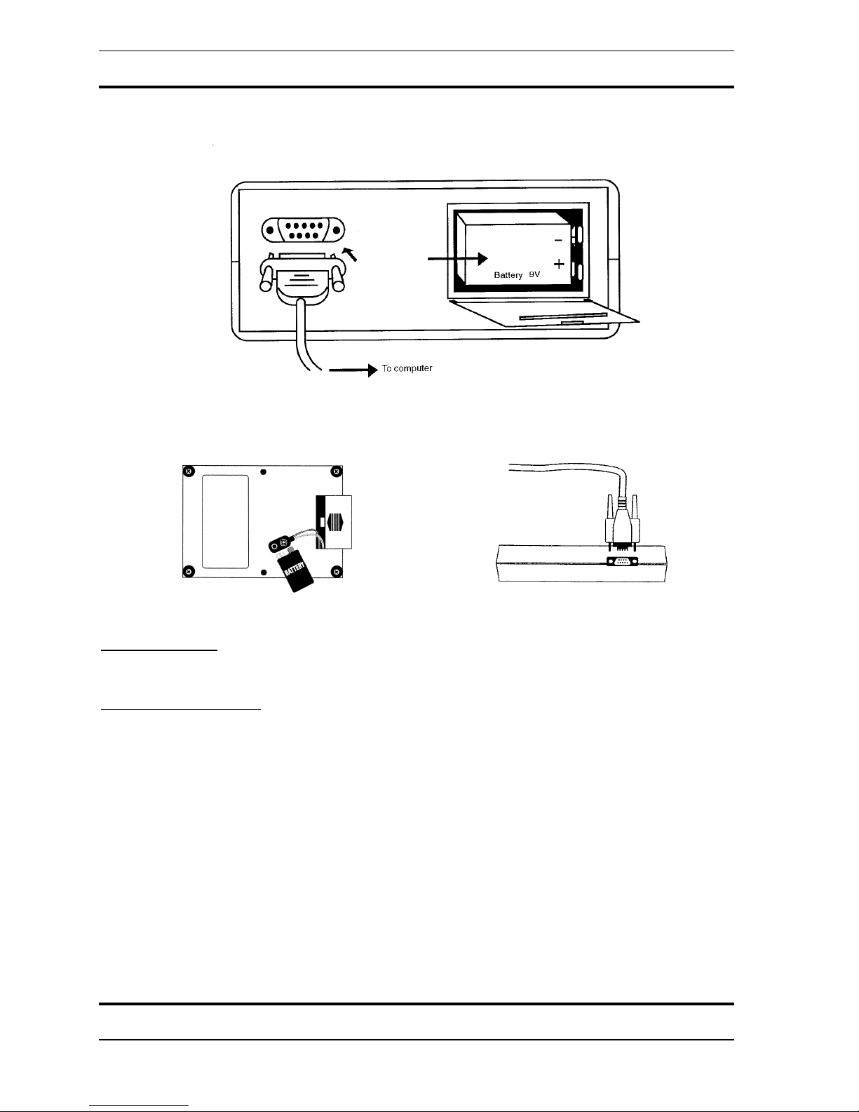
Install a Battery
Install a fresh 9-Volt battery (not included) in the battery compartment.
Connect Serial Cable
The WaveRider includes a 9-pin male to female serial cable.
1. Connect the female end of the serial cable to a serial port on the back of the computer.
The serial port on the computer has a male connector. If your computer does not have a
serial port see “Using a USB to Serial Port Converter” below.
2. Connect the male end of the serial cable to the connector on the back of the
WaveRider.
Copyright 1997-2004 Jonathan Purcell
All Rights Reserved
10

WaveRider Operating Manual
Hardware Installation Notes
Batteries
EVER connect theWaveRider to AC power lines using a voltage converter. This could
compromise the safety of the user.
Disposable Batteries
Recommended batteries include high quality 9-volt alkaline and lithium cells.
Rechargeable Batteries
Recommended batteries include 9-volt Nickel Metal Hydride (NiMH) cells. Nickel
Cadmium (NiCad) are not
recommended. Some people have used 12 volt gel cell motorcycle
batteries that sit outside the case of the WaveRider and can be recharged periodically with a
car battery type charger.
USB to Serial Port Connector
WaveRider comes with a USB to Serial Port Converter cable
The comm port used by WaveWare and the comm port used by the USB to serial port
converter driver must match. WareWave can only connect to comm ports 1, 2, 3, or 4. The
USB to serial port converter can be assigned to a wider range of comm ports but will only
work if assigned to ports 1,2,3, or 4. For detailed instructions see Setup USB To Serial Port
Converter Cable, below.
11
Copyright 1997-2004 Jonathan Purcell
All Rights Reserved

WaveRider Operating Manual
Software Installation
1. Exit all applications.
2. Insert the WaveWare CD.
3. Run setup.exe.
4. Follow the directions on the screen for installation.
5. When installation is complete drag the WaveWare icon onto your desktop.
Using the WaveRider for the First Time
1. Launch the WaveWare application.
2. WaveWare will prompt you to select a MIDI Device.
3. Select a MIDI Device according to the directions below.
4. Install the USB to Serial Cable according to the directions below.
5. Turn the WaveRider on by clicking the WaveWare ‘on’ button with your mouse or by
typing ‘ctrl’ + ‘o’ on your keyboard.
6. WaveWare will prompt you to select a comm (serial) port.
7. Select a comm port according to the directions below.
The comm port is properly installed when the red light on the WaveRider comes on and stays
on, and when the ‘on’ button in WaveWare is checked.
Set up the MIDI Device
The first time you launch the WaveWare application after installation you will be prompted
to select a MIDI device.
SOUNDBLASTER TYPE DRIVER (Most Common)
If you have a SoundBlaster or a SoundBlaster compatible sound card, you will be presented
with the following choices (or some variation):
MIDI Mapper
Microsoft synth
MIDI-OUT
SoundBlaster Connected to Speakers (Most Common)
If you are using your WaveRider with a SoundBlaster connected to a pair of speakers, choose
Microsoft synth or any other synth type device listed (but not MIDI-out or MIDI-mapper).
SoundBlaster (or MIDI card) Connected to External Synthesizer
If you are using an external synthesizer connected to your sound-card or MIDI-card you will
need to select either MIDI OUT or MIDI MAPPER.
This type of sound card allows you to send MIDI data to either
sound card) or to an external synthesizer, (but not both simultaneously).
MPU-401 TYPE DRIVER
If your sound card uses an MPU-401 type driver, it will send data to the internal synthesizer
and
to the MIDI outs simultaneously.
The preceding instructions assume that your sound-card is properly installed for Windows. If
your sound card is not properly installed, contact your sound card manufacturer to obtain the
appropriate drivers and advice.
the internal synthesizer (in the
Copyright 1997-2004 Jonathan Purcell
All Rights Reserved
12

WaveRider Operating Manual
SETUP USB TO SERIAL PORT CONVERTER CABLE
INSTALL DRIVER, CONNECT CABLE, CONNECT WAVERIDER
1. Run Setup.exe and follow installation instructions. (From CD).
2. Run the file CDM.exe (USB to Serial Comm Port Cable Driver). (From CD).
3. Connect the USB to Serial Comm Port Cable.
4. Install a fresh battery in the WaveRider and connect the WaveRider to the USB to Serial
Comm Port Cable.
SELECT CORRECT COMM PORT IN WAVEWARE AND USB TO SERIAL PORT DRIVER
The serial (comm) port specified by WaveWare (WaveRider Software) and the serial port specified
by the USB to Serial Port Cable Driver must match.
Comm port setting must be 1 through 4 and must be the same for both WaveWare and the USB to
Serial Port cable.
Every computer is different.
Some comm ports may already be in use.
You may need to try several comm port assignments until you find one that works.
Windows may indicate that a comm port is in use when it is not, or is not in use when it is.
Click the ‘on’ box in WaveWare to turn the WaveRider on. If the settings are correct the ‘on’ box will
remain checked, the red light on the WaveRider will come on and remain on, and the software will run
without error messages.
SELECT COMM PORT IN WAVEWARE (WAVERIDER SOFTWARE)
1. From the ‘Options’ Menu in WaveWare, select ‘Change Comm Port’.
2. Choose the appropriate Comm Port Setting.
SELECT COMM PORT FOR USB TO SERIAL PORT DRIVER (WINDOWS VISTA)
1. Select ‘System’ from the Control Panel.
2. Select ‘Device Manager’ from Tasks.
3. If necessary provide permission to continue.
4. Expand ‘Ports’.
5. Right click on ‘USB to Serial Comm Port (Comm x)’ and choose ‘properties’.
6. Select the ‘Port Settings’ tab.
7. Select the ‘Advanced’ Button.
8. Choose the appropriate comm port setting.
SELECT COMM PORT FOR USB TO SERIAL PORT DRIVER (WINDOWS XP)
1. From the control panel select ‘system’.
2. Choose the ‘hardware’ tab.
3. Select ‘Device Manager’ button.
4. Expand ‘Ports’.
5. Right click on ‘Prolific USB to Serial Comm Port (Comm x)’ and choose ‘properties’.
6. Select the ‘Port Settings’ tab.
Select the ‘Advanced’ Button.
7.
8.
Choose the appropriate comm port setting
13
Copyright 1997-2004 Jonathan Purcell
All Rights Reserved

WaveRider Operating Manual
One Page Operational Overview
Double clicking on any window brings up that window’s dialog box.
Biological channels are A & B (WaveRider jr./2CX), and A, B, C, & D (WaveRider Pro).
To raise and lower the gain (amplification) on a specific channel use the arrow keys on the
keyboard when a strip chart (brain, muscle or heart) for that channel has the input focus
active window is the window with the input focus
(the active window has a title bar of a
different color).
Do not try to play with biological signals (especially brainwaves) unless you are sure that you
have a good connection and a solid reliable signal.
LOAD CONFIGURATION in the FILE menu allows you to select a new configuration file.
SAVE CONFIGURATION in the FILE menu saves the setup that you have on your screen.
If you give the configuration the name ‘waveware.cfg’ it will become the default
configuration that is loaded when WaveWare is launched.
NEW ARCHIVE in the FILE menu allows you to save biological data.
OPEN ARCHIVE in the FILE menu allows you to replay stored biological data.
The use categories of configuration and archive files must match.
Ctrl + O Turns the WaveRider on and off.
Ctrl + F Freezes and unfreezes the display.
Ctrl + R Starts recording in record mode.
F1 Starts help
F3 Mutes the sound
F4 Unmutes the sound
Low Battery Is indicated by the outside of the battery slider becoming red.
. The
Copyright 1997-2004 Jonathan Purcell
All Rights Reserved
14

WaveRider Operating Manual
15
Copyright 1997-2004 Jonathan Purcell
All Rights Reserved
WaveRider Operating Manual
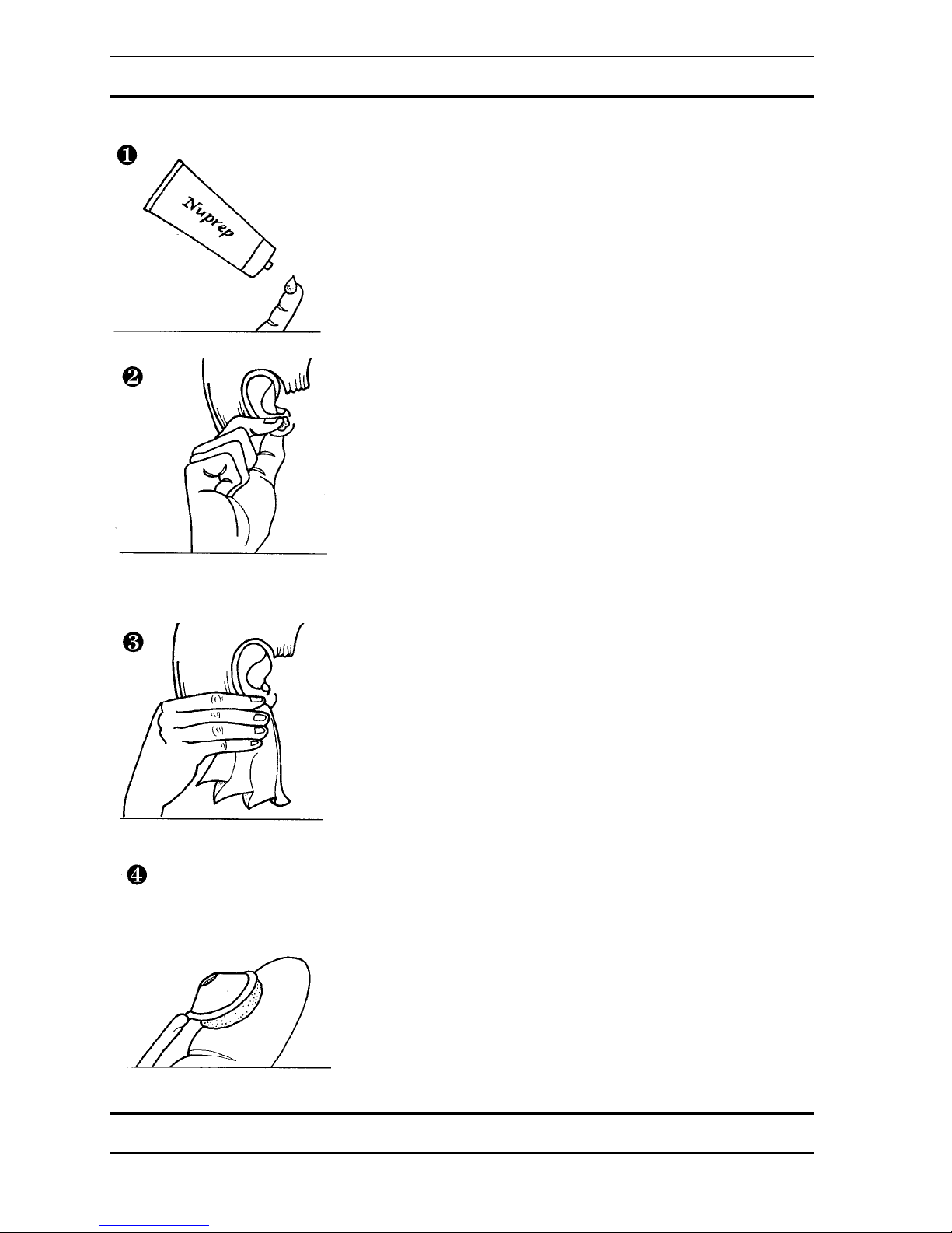
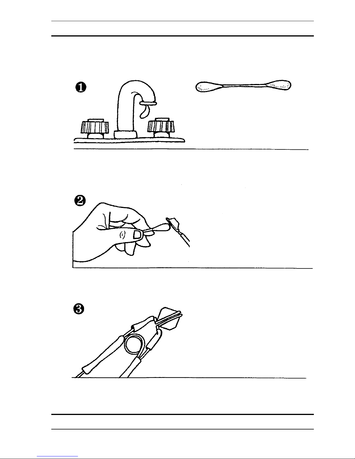
Connecting Brainwave Electrodes
Put a small amount of skin preparation gel (NuPrep) on a finger.
Rub the skin preparation gel into the earlobes and the electrode site(s) on the head.
The skin preparation abrades the top dead layer of the skin making for lower skin impedance
and a better connection.
Wipe off any excess skin preparation with a tissue.
Copyright 1997-2004 Jonathan Purcell
All Rights Reserved
16
WaveRider Operating Manual
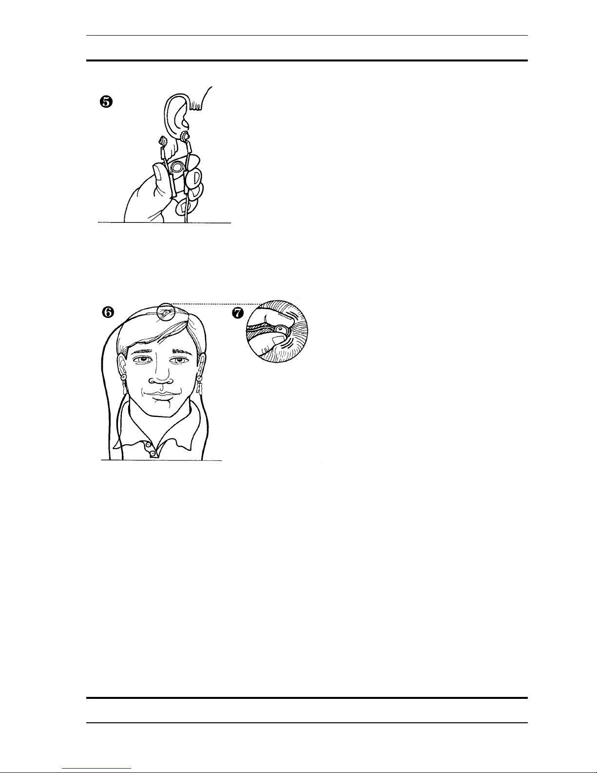
Put a dab of conductive paste (Ten20) in each head electrode and in each cup of both ear
electrodes.
Attach an earclip to each earlobe. Make sure that each ear clip makes good contact with its’
ear lobe. You may need to gently re-bend the ear clips if they become bent, or no longer fully
close.
Use your fingers to move hair out of the way of the head electrode site. Place the head
electrode firmly on the electrode site making sure that the rim of the electrde sits flat on the
head with a minimum of hair beneath it. To achieve the best connection you may need to
rotate the electrode between your thumb and forefinger while keeping the rim of the electrode
flat on the head. Place the electrode wires so that they are not pulled during the session.
17
Copyright 1997-2004 Jonathan Purcell
All Rights Reserved

WaveRider Operating Manual
Tips for Electrode Use
• If you adjust the electrodes, wait for the signal to settle.
• Don't play with the wires while using the WaveRider.
• A poor connection may get better if the electrodes remains on the head for a few
minutes
• A good electrode connection may go bad.
If this happens try the following approaches listed in order of increasing effort:
1. adjusting the electrode and ear clips and waiting for the signal to settle,
2. wiping the paste off and re-applying the electrode and ear clips,
3. wiping the paste off with a warm wet washcloth, cleaning the electrodes and
starting over.
Conditions Necessary for Good Electrode Contact
Before collecting brainwaves make sure:
• The signal indicates a good quality connection. (See below).
• Electrodes were thoroughly cleaned with hot water and cotton swabs immediately
after previous use.
• Skin is clean and free of dirt, sweat, oils, and cosmetics.
• Electrode site and ears are prepped with NU-Prep and/or alcohol.
• The head and ear electrodes are filled with paste and well adhered to the sensor site.
• The rim of the electrode is flat on the head.
• The electrode lead wire plug is fully seated in the WaveRider jack.
•
All hair is moved out of the way of the electrodes.
• The lead wires are not tangled.
Copyright 1997-2004 Jonathan Purcell
All Rights Reserved
18

WaveRider Operating Manual
Notes on Attaching Brainwave Electrodes
Attaching electrodes is more of an art than a science. It is not unusual for new users of
electrodes to have difficulty establishing a good brainwave electrode contact.
Electrode contact is extremely important. If electrodes do not make a good contact the
WaveRider will display random environmental noise rather than electrophysiological data. If
signals resembling brainwaves are displayed that appear identical whether or not the
electrodes are attached to the body, this indicates a poor connection.
A bad signal may be caused by a poor electrode connection and/or improper leadwire
placement. Electrode contact and leadwire placement are the most important aspects of noise
cancellation.
Sources of poor electrode contact include:
• Poorly attached electrodes,
• High skin impedance (due to skin that is oily, dirty or that has a lot of dead skin cells),
• Dirty or oxidized electrodes. (See below for information on cleaning electrodes).
Sources of improper leadwire placement include:
• Long lead wires,
• Lead wires being moved,
• Lead wires that pass by a source of electrical noise such as a computer monitor.
How to Determine Electrode Contact Quality
Whether a good signal has been achieved is determined by viewing the strip chart of the
channel to which the electrodes are attached. Poor electrode contact can result in the strip
chart displaying two different conditions. In the first condition the signal displays
insufficient amplitude ( i.e. vertical movement) under appropriate amplification (usually
range 7 for brainwaves). The signal should typically occupy at least 30% of the vertical
height of the strip chart window under appropriate amplification. In the second condition a
signal with substantial amplitude is displayed, but the signal displays environmental noise
rather than a biological signal. The environmental noise will usually be interference from 50
or 60 hertz power lines, but can also be caused other electronic devices such as computer
monitors.
19
Copyright 1997-2004 Jonathan Purcell
All Rights Reserved
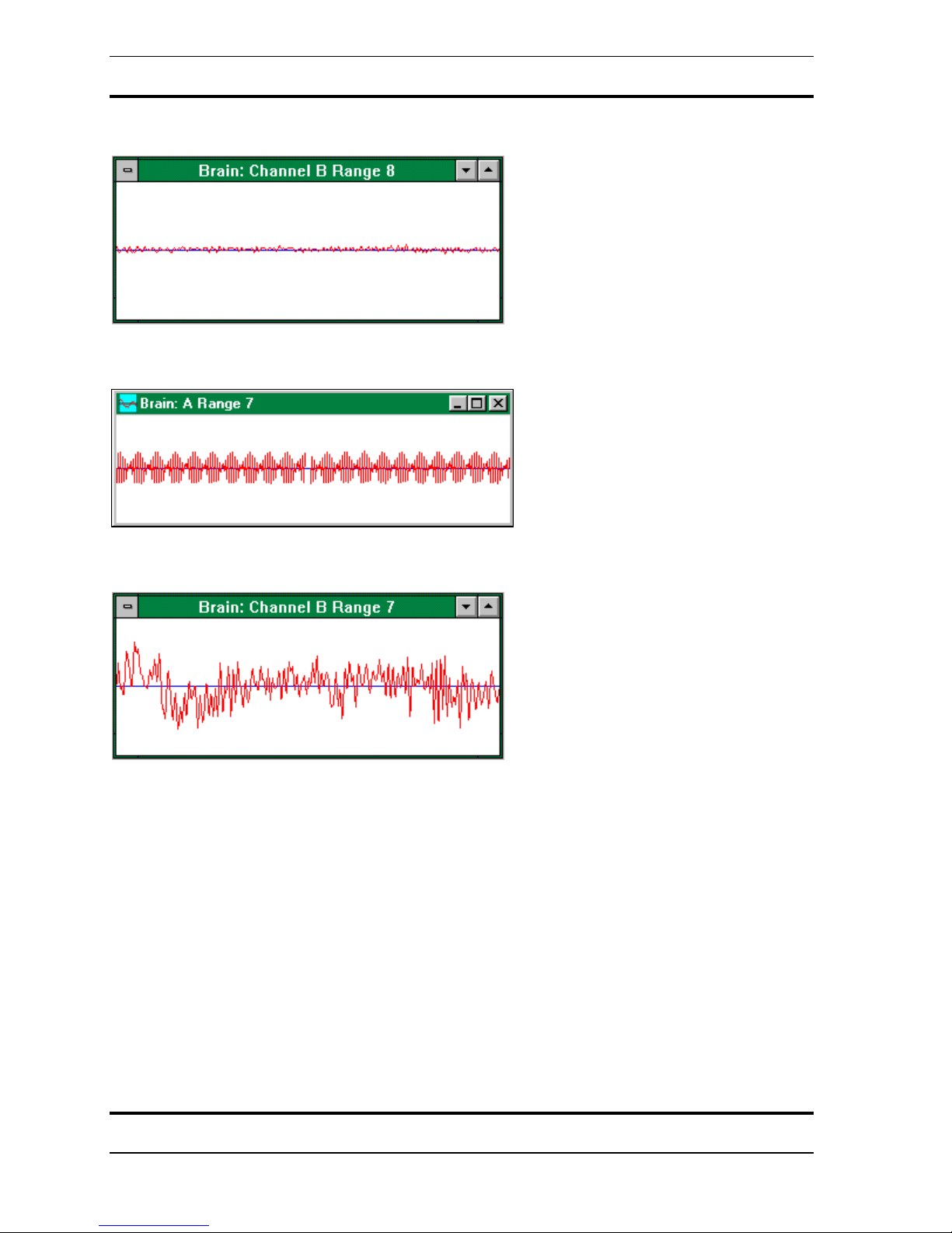
Insufficient amplitude:
Environmental noise:
WaveRider Operating Manual
Good signal:
Changing Amplification
The WaveRider has user selectable hardware amplification. Each range of amplification is
numbered 1 thru seven in order of increasing amplification. The amplification is changed by
raising and lowering the up and down arrow keys on the keyboard when a strip chart window
has the input focus. The active window is the window with the input focus.
If the amplification is too high, the signal will crash into the top and bottom rails of the
amplifier. This will saturate the amplifier and will cause large parts of the signal to not truly
reflect the biological signal being observed.
There is a notch filter that blocks out the power distribution frequency. In countries that use
60 hertz power this is a 60 hertz filter. In countries that use 50 hertz power this is a 50 hertz
filter. There is a conversion kit available for individuals who operate between countries with
different power distribution frequencies. Since Japan uses both 50 & 60 hertz a special
version is available that filters out both 50 & 60 hertz.
Copyright 1997-2004 Jonathan Purcell
All Rights Reserved
20
WaveRider Operating Manual
Caring For Electrodes
Ear and head electrodes should be carefully cleaned immediately after every use.
Use hot running water and cotton swabs to clean the conductive paste from the head and ear
electrodes.
Warm and wet each head and ear electrode under hot running water while cleaning the
conductive paste with a cotton swab.
Be careful not to twist the ear clips out of position. The ear clips should close completely and
the two halves should remain parallel.
21
Copyright 1997-2004 Jonathan Purcell
All Rights Reserved

WaveRider Operating Manual
Brainwave electrodes can become oxidized from failure to clean after use, age, or exposure to
air. Oxidation can be visible or invisible. Minor oxidation can be remedied by cleaning
electrodes with alcohol, or by dipping in a liquid silver cleaning solution available at most
drug stores.
Copyright 1997-2004 Jonathan Purcell
All Rights Reserved
22
WaveRider Operating Manual
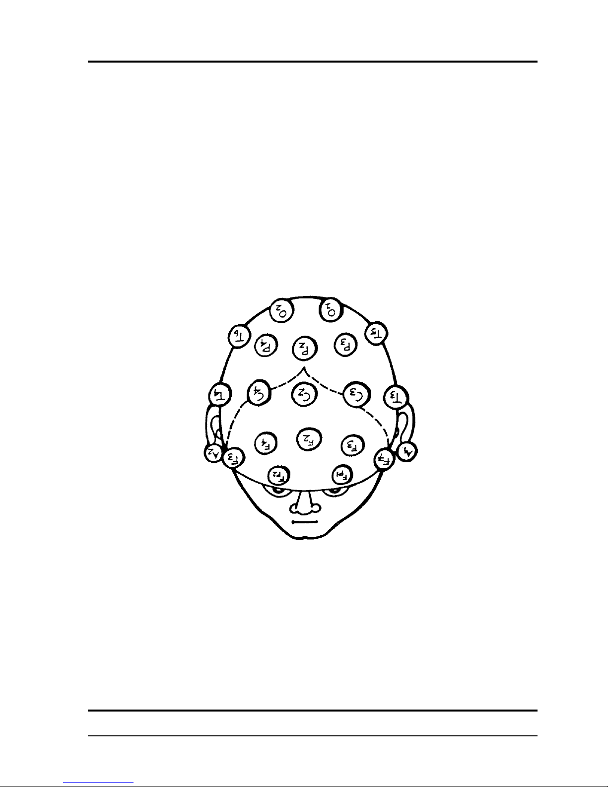
Electrode Placement
There is a standard pattern for placing electrodes on the scalp for the measurement of
brainwaves. This is known as the 10-20 system. Each electrode site has a name composed of
a letter and a sub-script. Each letter (with the exception of C which stands for center) refers to
the cerebral lobe over which the electrode is placed, i.e. T=temporal, P=parietal, O=occipital,
F= frontal, Fp=pre-frontal. The odd-numbered subscripts are on the left side of the head, the
even numbered sub-scripts are on the right. The subscript z is on the center line. Generally an
active electrode is placed on one ear lobe and a reference electrode on the other earlobe.
23
Copyright 1997-2004 Jonathan Purcell
All Rights Reserved

WaveRider Operating Manual
Copyright 1997-2004 Jonathan Purcell
All Rights Reserved
24

WaveRider Operating Manual
LEARNING THE HEART, GSR, BRAIN AND MUSCLE MODES
25
Copyright 1997-2004 Jonathan Purcell
All Rights Reserved
WaveRider Operating Manual
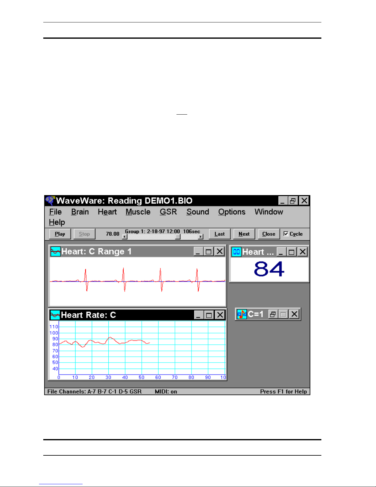
HEART
Use the Heart configuration to look and listen to your heart rate change.
1. From the FILE menu choose LOAD CONFIGURATION.
2. Select HEART.CFG.
3. Connect the electrodes as in the diagram. Use the disposable electrodes and lead wires
provided.
4. Turn the WaveRider on by clicking the ON
“O”.
5. The heart strip chart should have a clean signal if the electrodes are properly connected.
To learn how to modify the configuration refer to:
• STRIP CHART in the WINDOWS Section of the Key Concepts Chapter of this
manual,
• HEART RATE in the PROGRAMMING WAVEWARE section of this manual,
• or double click on any of the windows to view and modify their properties.
button with your mouse or by using “Ctrl” +
Copyright 1997-2004 Jonathan Purcell
All Rights Reserved
26
WaveRider Operating Manual
CHANNELS USED FOR HEART MODE VARY BETWEEN MODELS AND MAY
DIFFER FROM WHAT IS SHOWN
27
Copyright 1997-2004 Jonathan Purcell
All Rights Reserved
WaveRider Operating Manual
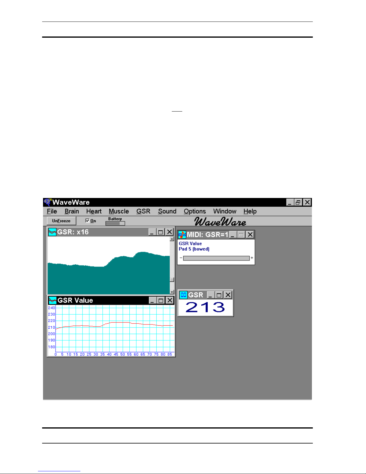
GSR
Use the GSR configuration to learn how to modify your state of arousal.
1. From the FILE menu choose LOAD CONFIGURATION.
2. Select GSR.CFG.
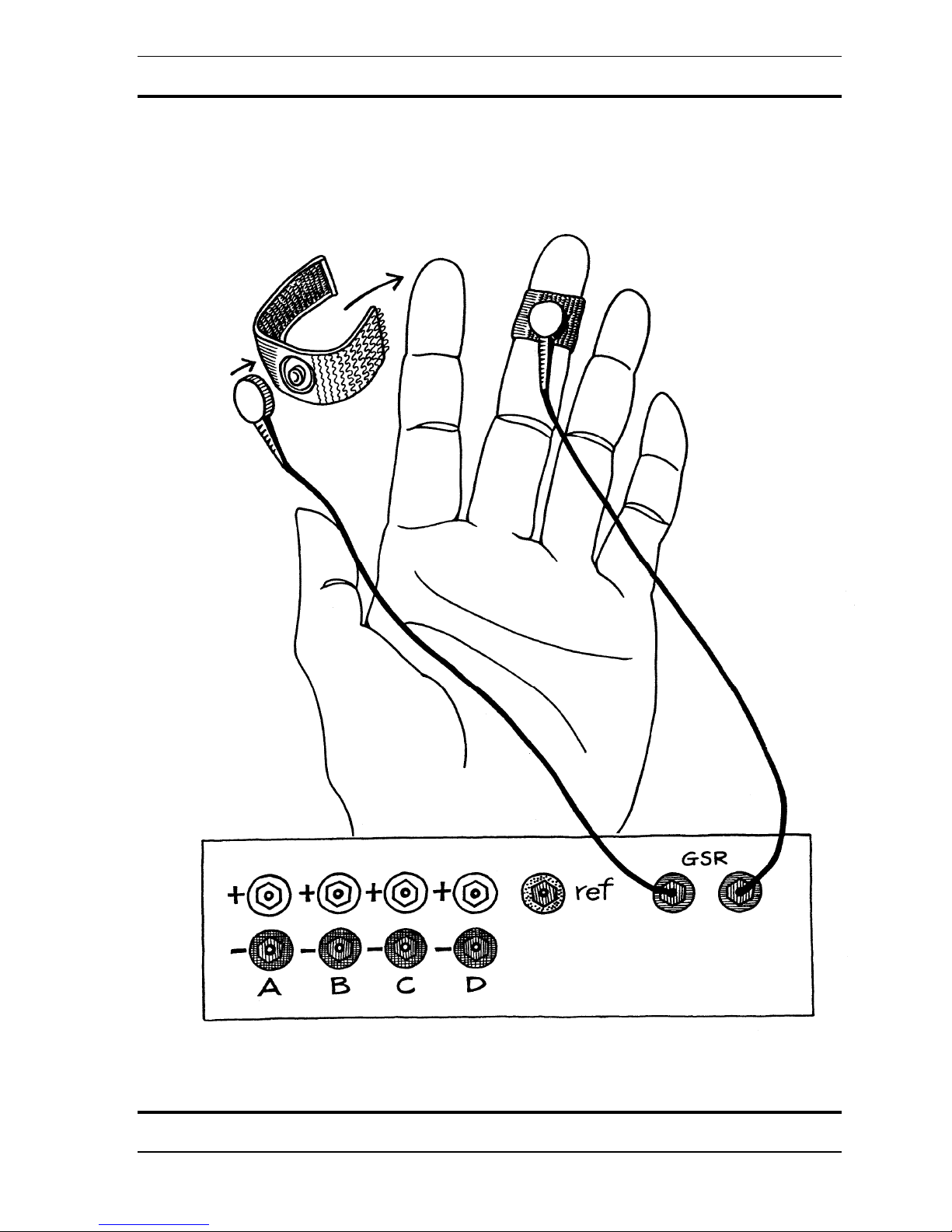
3. Connect the electrodes as in the diagram. Use the finger electrodes and lead wires
provided. Use no electrode gel or paste.
4. Turn the WaveRider on by clicking the ON
“o”.
5. The GSR moves relatively slowly. Try taking deep breaths or thinking about your debts
or ex-lover.
To learn how to modify the configuration refer to:
• GSR GRAPH in the WINDOWS Section of the KEY CONCEPTS CHAPTER of this
manual,
• GSR in the PROGRAMMING WAVEWARE section of this manual,
• or double click on any of the windows to view and modify their properties
button with your mouse or by using “Ctrl” +
Copyright 1997-2004 Jonathan Purcell
All Rights Reserved
28
WaveRider Operating Manual
29
Copyright 1997-2004 Jonathan Purcell
All Rights Reserved
WaveRider Operating Manual
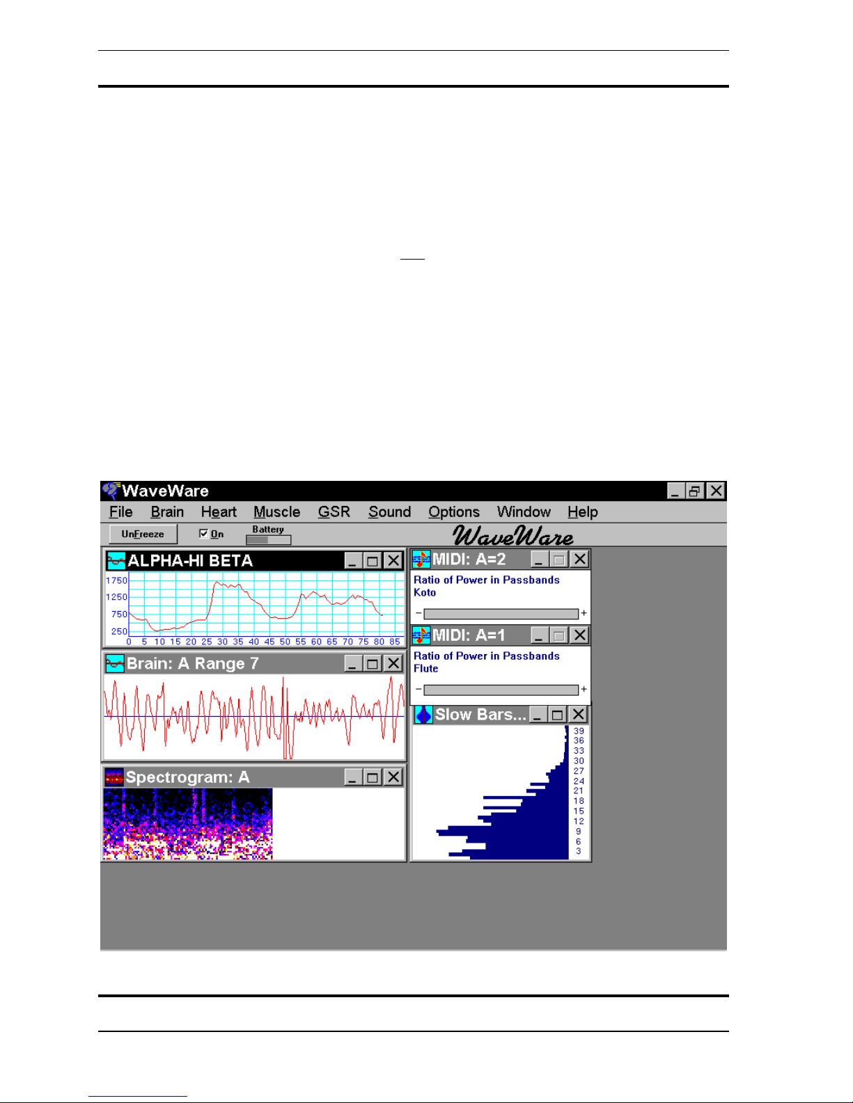
BRAIN
Use the ALFAKOTO configuration to use your brainwaves to relax.
1. From the FILE menu choose LOAD CONFIGURATION.
2. Select ALFAKOTO.CFG.
3. Connect the electrodes as in the diagram. Use the cup electrodes supplied and the ten20 paste. Make sure that the skin is clean and you have a good contact.
4. Turn the WaveRider on by clicking the ON
“o”.
5. The brain strip chart should have a clean signal if the electrodes are properly connected.
6. Close your eyes. Relax. Drop your shoulders. Make the note go up.
To learn how to modify the configuration refer to:
• STRIP CHART in the WINDOWS Section of the KEY CONCEPTS CHAPTER of
this manual,
• THE GENERAL GRAPHICS AND THE MIDI OPTIONS DIALOG BOXES in the
PROGRAMMING WAVEWARE section of this manual,
• or double click on any of the windows to view and modify their properties
button with your mouse or by using “Ctrl” +
Copyright 1997-2004 Jonathan Purcell
All Rights Reserved
30

WaveRider Operating Manual
31
Copyright 1997-2004 Jonathan Purcell
All Rights Reserved

WaveRider Operating Manual
MUSCLE
Use the muscle configuration to relax or play music with your muscles.
1. From the FILE menu choose LOAD CONFIGURATION.
2. Select MUSCLE.CFG.
3. Connect the electrodes as in the diagrams, or put them on a different set of muscle
groups. Use the disposable electrodes and lead wires provided.
4. Turn the WaveRider on by clicking the ON
“o”.
5. The muscle strip chart should have a clean signal if the electrodes are properly connected.
6. Flex or relax your msucles
To learn how to modify the configuration refer to:
• STRIP CHART in the WINDOWS section of this manual,
• PEAK TO PEAK AMPLITUDE in the THE GENERAL GRAPHICS AND THE MIDI
OPTIONS DIALOG BOXES section of this manual,
• or double click on any of the windows to view and modify their properties.
button with your mouse or by using “Ctrl” +
Copyright 1997-2004 Jonathan Purcell
All Rights Reserved
32

WaveRider Operating Manual
33
Copyright 1997-2004 Jonathan Purcell
All Rights Reserved

WaveRider Operating Manual
Copyright 1997-2004 Jonathan Purcell
All Rights Reserved
34

KEY CONCEPTS
WaveRider Operating Manual
35
Copyright 1997-2004 Jonathan Purcell
All Rights Reserved

WaveRider Operating Manual
CHANNELS
WaveRider collects data on biological channels that are named by letters. Channels A & B
for the WaveRider jr./2CX and channels A, B, C & D for the WaveRider Pro.
WaveRider sends MIDI data out on numbered MIDI channels 1-16. It is important that the
MIDI channels specified do not conflict with each other.
USE CATEGORIES
WaveWare utilizes use categories to keep track of the type of data each biological channel is
acquiring. Use category is an assignment that a channel is given when the first window that
makes reference to it is opened. It is a somewhat invisible concept. The possible use
categories are BRAIN, HEART & MUSCLE. GSR is also a use category but GSR data can
only be acquired on the GSR channel.
Once a use category is assigned to a biological channel, WaveWare will not permit the
assignment of another use category to that channel unless all windows that reference that
channel are closed. After all windows that reference that channel are closed, a new use
category can be assigned by opening a new window.
When an archive file is recorded each channel is assigned a use category. When a
configuration file is created each channel is assigned a use category. In order to replay an
archive file through a configuration file, the use categories for each channel must match. If an
archive file and a configuration file are opened in which the use categories conflict, you will
be presented with a message that reads:
The file channels do not match the program setup
You will need to close the archive file and modify the configuration file so that there is no
conflict with the archive file. It may be helpful to look at the ARCHIVE INFORMATION in
the FILE MENU to see what use categories the biological channels have assigned to them in
the archive file.
Copyright 1997-2004 Jonathan Purcell
All Rights Reserved
36

WaveRider Operating Manual
FILE CREATION
WaveWare can create three types of files: configuration (.cfg) files, archive (.bio) files and
ascii (.txt) files.
Configuration Files
Configuration files store the templated setups that you see on your screen when you look at
WaveWare. They include the settings for each window as found in that window’s dialog box.
In addition they save global parameters such as colors, transform characteristics, and cycling.
SAVE CONFIGURATION in the FILE menu will save your configuration. If you use the
name waveware.cfg
that will be opened when WaveWare is launched.
LOAD CONFIGURATION opens a saved configuration file.
Archive Files
Archive files store unprocessed (raw time domain) biological data. These files can be of any
length and consume approximately 0.5 Megabyte/hour/channel in storage space.
To archive a live file.
1. Turn on the WaveRider.
2. Select NEW ARCHIVE from the FILE menu.
3. Choose a name that will describe the file. It will be given a .bio extension.
4. Use the Archive Options Dialog Box to select biological channels for recording, set the
Pre-Trigger Time
5. Click OK
6. WaveWare will be in RECORD MODE and will display a RECORD button.
7. When you click the RECORD BUTTON, WaveWare will begin to record.
Pre-Trigger Time
Pre-Trigger provides the ability to record data a few seconds prior to the time the record
button is hit. This allows one to record immediately after an event of interest is observed, or
after the subject settles down.
Files can be played back and further processed in playback mode. Use OPEN ARCHIVE
from the FILE menu to open recorded files. Archive files can be played back through any
configuration in which the use categories match.
for your configuration file it will become the default configuration file
(see below), and to write comments
37
Copyright 1997-2004 Jonathan Purcell
All Rights Reserved

WaveRider Operating Manual
ASCII FILE OUTPUT (Exporting to a spreadsheet)
Offline processed biological data may be exported to an ASCII (text) file. This data can be
opened and further processed in a spread sheet or statistical analysis package. The streams of
processed data stored in the ASCII file will correspond to the General Graphics Windows
present in the configuration file when the data is exported.
Directions for ASCII FILE OUTPUT
ASCII FILE OUTPUT will appear grayed out in the FILE menu unless both an archive file is
opened and a configuration file is opened that has at least one non-GSR General Graph
Window.∗
1. Select ASCII FILE OUTPUT from the FILE menu.
2. Create an 8 character name for your file at the prompt. This file will be given a .txt
extension.
3. Hit OK
Description of ASCII File
The ASCII file is comma delimited. Select the appropriate settings in your spread sheet to
make sure that the column breaks are put in the correct places.
The left most column is the time at which each processed data point was produced (in
seconds). The General Graphics Window with the finest time resolution in the configuration
file used during the export of data, will define the time resolution of the ASCII file. Some
data streams may be calculated at a coarser resolution and not fill up every cell. Some
columns of buffered data may not have data in the first few rows because, the buffered data is
not accurate until the first few readings have passed into the buffer.
Each General Graphics Window will create a column of numbers in the ASCII file. Each
column will be given either the default title of the window produced by WaveWare or the
name that was given to the General Graphics Window in the General Graphics Options
Dialog Box by the user.
∗
GSR General Graph may be output to ASCII but an additional non-GSR General Graphics window must be
included in the configuration file.
Copyright 1997-2004 Jonathan Purcell
All Rights Reserved
38

WaveRider Operating Manual
WINDOWS
The screens in WaveWare are composed of windows. Each window has a set of properties
that can be set in its' dialog box.
Any window’s dialog box may be accessed by double clicking on the middle of the window
with the left mouse button. Do not click on the titlebar, since this will maximize the window.
What follows is a brief description of some of the windows and their associated dialog boxes
in WaveWare .
The General Graphics and MIDI Output windows require more depth of explanation and are
treated in the PROGRAMMING WAVEWARE CHAPTER.
39
Copyright 1997-2004 Jonathan Purcell
All Rights Reserved

WaveRider Operating Manual
Strip Chart
The STRIP CHART command in the BRAIN, HEART and MUSCLE menus opens a
window that displays the raw biological signals , or displays the same signals as they are
later replayed from an archive file. The strip chart display is especially helpful in monitoring
the electrode connections, and making sure that the range of the WaveRider channel is set
properly.
Double clicking on the Strip Chart window opens an Options box
, which provides the ability
to change a number of settings affecting the strip chart display.
More than one channel may be displayed in the window; the default is to display two
channels, which could correspond to the left and right hemispheres of the brain.
By pressing the Up or Down arrow keys on the keyboard
while a strip chart window has the
input focus, the Range of the WaveRider channels may be raised or lowered. If more than
one channel is displayed in one window, those channels become linked; the ranges of linked
channels are always kept the same.
The strip chart window may be resized, minimized, or maximized.
Copyright 1997-2004 Jonathan Purcell
All Rights Reserved
40

WaveRider Operating Manual
Strip Chart Options Dialog Box
CHAEL
Choose among the WaveRider channels (or among the saved channels, if an archive file is
being read); the chosen channels will be displayed in this strip chart window, one above the
other. Some of the channel checkboxes may be grayed, indicating channels which have a
different use category.
If multiple channels are displayed in one window, those channels become Linked; the ranges
of linked channels are always kept the same.
MODE
Three types of strip chart display may be selected from; choosing among these only affects
the appearance of the strip chart window. The strip chart may be drawn using only the DOTS
representing the individual data points. Or the chart may be drawn using SOLID areas for
greater visibility. The default is to draw a continuous LINE representing the data.
SPACIG
The default x1 horizontal spacing uses one pixel per data point. If x2 or x3 are selected, each
point uses correspondingly more space in the window, making less data visible at one time.
GRID
By default, a single axis is drawn horizontally across each strip chart to indicate the zero
point of the signal. In addition, you may choose a grid indicating the amplitude of the signal
in microvolts, with or without the numerical values along the left, or you may choose a totally
plain strip chart display with neither grid nor axis.
RAGE
By pressing the Up or Down arrow keys while a strip chart window has the input focus, the
Range of the WaveRider channels may be raised or lowered. The range is not changed
directly from the options dialog box.
ERASE AFTER EVERY SWEEP
Erases the previous signal trace before the new trace is drawn.
41
Copyright 1997-2004 Jonathan Purcell
All Rights Reserved

WaveRider Operating Manual
Fast Bars and Slow Bars
The FAST BARS and SLOW BARS commands in the BRAIN menu open windows that
display the frequencies of the brain signals. Both windows derive their frequencies from a
Fast Fourier Transform (FFT). The fast bars window calculates the FFT as fast as it can. The
Slow slow bars window displays the frequencies of the brain signals averaged over a selected
number of seconds.This averaging makes the slow bars display much easier to read and less
jumpy.
More than one channel may be displayed in the window. The default is to display two
channels, which could correspond to the left and right hemispheres of the brain.
Double clicking on the Fast Bars or Slow Bars window opens an Options box, which
provides the ability to change a number of settings affecting the display.
The slow bars window may be resized, minimized, or maximized.
Copyright 1997-2004 Jonathan Purcell
All Rights Reserved
42

WaveRider Operating Manual
Bar Graph Options
The Bar Graph Options dialog box allows you to change the appearance and characteristics of
the Fast Bars and Slow Bars windows.
Channels
Choose among the WaveRider channels (or among the saved channels, if an archive file is
being read); the chosen channels will be displayed in this bars window. Some of the channel
checkboxes may be grayed, indicating channels that have a different use category.
If multiple channels are displayed in one window, those channels become Linked; the ranges
of linked channels are always kept the same.
Timebase
The Slow Bars display differs from Fast Bars in that the Slow Bars display averages the
frequencies of the brain signals over a selected number of seconds.
A longer timebase renders the Slow Bars display more stable and hence easier to read, while
a shorter timebase makes events such as a momentary burst of a certain frequency more
visible.
umbered Frequencies
If this box is checked, the Bars display includes a post which shows the frequencies
represented by the bars, numbered from 1 to 40 Hz.
Style
The arrangement of the bar graphs within the window may be selected, by clicking on the
picture that represents your preference. This allows you to arrange the window so that the
display reflects the positions of the electrodes on the scalp. The channels are always
displayed in order, from the top left across the window.
43
Copyright 1997-2004 Jonathan Purcell
All Rights Reserved

WaveRider Operating Manual
Spectrogram
The spectrogram display makes it possible to view the frequencies of the brain as they have
changed over a period of time. Selecting SPECTROGRAM in the BRAIN menu opens this
window. Color or shading is used to depict the amount of power present in each of the
frequency bands. The brighter the color, the more power. The frequencies are represented
vertically from one to forty hertz. One could think of the spectrogram display as a slow bars
turned on edge with the length of the bars being represented by the brightness of color.
More than one channel may be displayed in the window.
Double clicking on the Spectrogram window opens an Options box, which provides the
ability to change a number of settings affecting the spectrogram display. The colors of the
spectrogram can be changed with the COLORS dialog box available from the OPTIONS
menu.
The spectrogram window may be resized, minimized, or maximized.
Copyright 1997-2004 Jonathan Purcell
All Rights Reserved
44

WaveRider Operating Manual
Spectrogram Options Dialog Box
The Spectrogram Options Dialog Box provides the ability to change the appearance and
characteristics of the Spectrogram window.
Channels
Choose among the WaveRider channels (or among the saved channels, if an archive file is
being read); the chosen channels will be displayed in this Spectrogram window, one above
the other. Some of the channel checkboxes may be grayed, indicating channels that have a
different use category.
If multiple channels are displayed in one window, those channels become Linked; the ranges
of linked channels are always kept the same.
Timebase
Each of the vertical strips of color displayed in the Spectrogram window represents an
average of the frequencies over a selected number of seconds, ranging from a half second up
to 32 seconds. A longer timebase allows the Spectrogram window to display a record of the
frequencies over a longer period of time (up to several hours), while a shorter timebase
makes events such as a momentary burst of a certain frequency more visible.
Spacing
The default horizontal spacing uses one pixel per vertical strip. If x2 or x3 are selected, each
strip uses correspondingly more space in the window, making less data visible at one time.
Sample Color Bar
A sample is shown of the color range which is used to represent the frequencies. The
frequencies with the least amount of activity are depicted using the colors on the left end of
the sample, while frequencies with the greatest activity show as colors on the right end of the
sample. To select a different color scheme, choose the COLORS... command from the
OPTIONS menu.
45
Copyright 1997-2004 Jonathan Purcell
All Rights Reserved

WaveRider Operating Manual
GSR Graph
Selecting GSR GRAPH from the GSR menu opens a window that displays the Galvanic
Skin Response (GSR), or displays the same signal as it is later replayed from an archive file.
The display is a graph of the skin conductance ranging from low (often associated with a
lowered stress level), to high.
Double clicking on the GSR Graph window opens an Options box, which provides the ability
to change a number of settings affecting the display. The magnification of the display may be
adjusted with the up and down arrow keys on the keyboard, allowing either the full range of
the GSR signal to be displayed in a single window, or only a portion of the GSR range to be
shown with much greater resolution. The portion of the range may be automatically adjusted
as the GSR signal varies.
The GSR Graph window may be resized, minimized, or maximized.
Copyright 1997-2004 Jonathan Purcell
All Rights Reserved
46

WaveRider Operating Manual
GSR Graph Options Dialog Box
The GSR Graph Options Dialog Box provides the ability to adjust the appearance and
characteristics of the GSR Graph window.
Mode
Four types of display may be selected. The GSR graph may be drawn using only the DOTS
representing the individual data points. The default mode uses SOLID areas for greater
visibility. A continuous LINE may be drawn to represent the data, or a THICK line may be
selected.
Spacing
The default x1 horizontal spacing uses one pixel per data point. If x2, x3,or x4 are selected,
each point uses correspondingly more space in the window, making less data visible at one
time.
Magnification
By selecting a magnification, ranging from x1 through x16, a varying amount of detail may
be seen in the GSR data. As the magnification is increased, more detail becomes visible, but
a smaller range of data may be viewed in a given size window. A greater magnification, will
cause the scrollbar to make more frequent adjustments to bring the current data into view.
Scrolling
If MAGNIFICATION is set so that the full range of GSR data cannot be displayed in the
window, a scrollbar appears. If SCROLLBAR is selected, the scrollbar may be moved
manually
graph will shift automatically
to shift the the desired data into view. If AUTOMATIC scrolling is selected, the
, always keeping the most recent GSR data visible. In the
automatic mode, the scrollbar is not used to shift the display, but only serves to show which
part of the range is being shown.
47
Copyright 1997-2004 Jonathan Purcell
All Rights Reserved

WaveRider Operating Manual
MIDI
MIDI stands for the Musical Instrument Digital Interface. MIDI is a protocol or language
spoken between electronic musical instruments and computer based music software and
hardware. MIDI sends messages that are composed of note and velocity information. The
note number refers to the pitch of the note and consists of a number between 0 & 127.
Velocity is the loudness or volume of the note. Velocity also varies between 0 & 127. MIDI
is a keyboard or piano based metaphor and it is sometimes helpful to think of it as such. Each
time you produce a note there are two pieces of information sent along: the note and the
velocity. The velocity (or loudness) is so called because it is analogous to hitting the key on
the keyboard. The harder you hit it, the higher its’ velocity, the louder the note.
There are several other types of messages in MIDI, controller messages, voice messages,
pitch bend, and system exclusive messages. Voice messages set the voice or instrument on
each channel. Continuous controllers provide the ability to do such things as add sustain,
tremolo or pan between speakers. Sys ex or System Exclusive messages implement features
that are specific to a particular make and model of synthesizer. WaveWare does not
implement Sys ex messages but many synthesizers provide the mapping of controllers and/or
notes to sys ex.
Most implementations of MIDI have 16 channels . Some early sound cards had 4 channels.
Some high end systems provide the ability to multiplex providing supplemental banks of
channels in multiples of 16 channels (16, 32 etc.). MIDI makes use of numbered channels.
WaveRider has lettered biological channels (A,B,C,D).
You can map multiple biological parameters from a single biological channel to
multiple MIDI channels simultaneously. (You could conceivably map the output of one
biological channel to 16 MIDI channels). (e.g. you can map the coherence from channel A
to MIDI channel 1 and the Alpha from channel A to MIDI channel 2).
Generally it is not a good idea to have more than one biological output go to the same MIDI
channel unless you are careful to assign note values that do not conflict. If there is a conflict
you will probably notice it when one voice ‘grabs’ control of another channel.
Copyright 1997-2004 Jonathan Purcell
All Rights Reserved
48

WaveRider Operating Manual
MIDI STRATEGIES
When a scale is chosen in the MIDI OPTIONS DIALOG BOX particular attention should be
paid to the choice of range of MIDI notes. If the object is to make the output sound in scale
the tops and bottoms of the range should be octaves, fifths or some other significant note in
the scale structure.
The MIDI note numbers and their corresponding notes are provided below. Middle C is note
60.
NOTE # NOTE NOTE #
NOTE
36 C 66 F#
37 C# 67 G
38 D 68 G#
39 D# 69 A
40 E 70 A#
41 F 71 B
42 F# 72 C
43 G 73 C#
44 G# 74 D
45 A 75 D#
46 A# 76 E
47 B 77 F
48 C 78 F#
49 C# 79 G
50 D 80 G#
51 D# 81 A
52 E 82 A#
53 F 83 B
54 F# 84 C
55 G 85 C#
56 G# 86 D
57 A 87 D#
58 A# 88 E
59 B 89 F
60 C 90 F#
61 C# 91 G
62 D 92 G#
63 D# 93 A
64 E 94 A#
65 F 95 B
96 C
Here are some suggestions for musical strategies:
49
Copyright 1997-2004 Jonathan Purcell
All Rights Reserved

WaveRider Operating Manual
To play a blues riff start at the root and go to the fifth or seventh in one octave for the range
of the signal.
To play a single pitch set the upper and lower note range to the same value.
To play at a uniform volume set the upper and velocity range to the same value.
To have the note get lower and softer with more relaxation switch the order of the note and
velocity values. Left hand side of range of MIDI values contains the higher value and the
right hand side contains the lower value. E.g. More theta produces lower volume and lower
pitch.
Try setting up several inputs that play one note only, but when played together form a chord.
For a rising parameter there are four options
1. note raises, velocity raises
2. note raises, velocity lowers
3. note lowers, velocity raises
4. note lowers, velocity lowers (good for relaxation)
Copyright 1997-2004 Jonathan Purcell
All Rights Reserved
50

WaveRider Operating Manual
FFTS, DIGITAL FILTERS AND SIGNAL PROCESSING
The Fast Fourier Transform (FFT) is a mathematical prism. Just as a prism splits white light
into its component colors, an FFT splits a signal into its component frequencies. Another
perspective is that the FFT sorts a signal into a set of frequency bins. The WaveRider's FFT
sorts a signal into frequency bins one hertz wide.
An FFT takes a window or set of data points and converts this time window of data into a set
of frequencies. The input data is considered to be in the "time domain," the output data is in
the "frequency domain." The WaveRider uses a one second window. In the slow bars mode a
new window is begun every .25 seconds.
A digital filter performs a transfer function consisting of a collection of stop and pass bands.
Pass bands let specific frequencies pass. Stop bands stop certain frequencies from passing.
Most digital filters used in WaveWare have three bands, two stop bands and a pass band in
the middle. A digital filter also uses a window of data points. Unlike the FFT this window is
recalculated every time a new data point comes in. This makes digital filters much more
responsive to signal variations than FFTs.
51
Copyright 1997-2004 Jonathan Purcell
All Rights Reserved

WaveRider Operating Manual
Transform controls the characteristics of the global FFT parameters used in WaveWare.
Select TRANSFORM... from the OPTIONS menu in WaveWare. Windowing refers to a set
of co-efficients by which the data coming into the FFT are multiplied. The Windows have
been designed to optimize time-frequency resolution trade-offs. The logarithmicity factor
changes the scaling of the output of the FFT. A higher number will increase the apparent
power of lower powered frequency bands in relation to the higher powered frequencies.
Windowing
Each time the frequency transform is computed, it is calculated over a set of 128 consecutive
data points; this set of points is referred to as a Window. It is often desirable to attenuate the
data points near the window ends.
The Rectangular window uses the data points as they are, without attenuation; this option
requires the least computation, thus reducing system loading and speeding response slightly.
The Hamming, Hanning, Triangular, and Blackman windowing options represent various
mathematical approaches to the attenuation of these end points. They offer different tradeoffs between sensitivity of the transform, and reduction of harmonics.
Log Power
After the frequency transform is computed, the power is calculated for each frequency band
from 1 to 40 Hz. When this power spectrum is plotted, for example in the fast bars window,
the power may be mapped linearly into the length of bars (Log Power = 0), or the power may
be mapped logarithmically into the length of bars. Selecting greater Log Power numbers
serves to accentuate the low-power frequency bands, making them more visible relative to the
higher-power bands. Looking at Brain data, this markedly improves the visibility of the Beta
region.
Copyright 1997-2004 Jonathan Purcell
All Rights Reserved
52

WaveRider Operating Manual
MINDGAMES: WAVERIDER LESSON PLANS
53
Copyright 1997-2004 Jonathan Purcell
All Rights Reserved

WaveRider Operating Manual
Introduction
The Mind
Filled with confusion
Who is its' guide?
Make it
A sharp point
A smooth lake
A gentle breeze
A mountains' root.
-Bu Zhen Tsu
Have you ever gone to a party and thought about work the whole time?
Or thought about the evening too much at work?
Or carried on an internal dialogue when you should have been listening to what your lover
was trying to tell you?
Have you ever wished that you could just "change your mind" but have been unable to do it?
By learning the sensations associated with specific brainwave states, you can learn to enter
and leave mental states of concentration, relaxed attentiveness, or deep relaxation.
Using the WaveRider can help you to gain this sense of awareness. Through repeated
practice, you will learn what you need to do to enter into and switch between mental states in
real life situations.
One way to think of the brainwave frequency spectrum is as a continuum of arousal. The
delta waves of deep sleep are on one end, the high frequency beta waves associated with an
active mind are on the other end. The alpha peak or dominant alpha frequency is a key point
in this continuum. Frequencies above it, (Beta, SMR) tend to stimulate arousal. Frequencies
below it (Theta, Delta), tend to decrease arousal. It is thought by some, that alpha represents
an idling state, which portions of the brain return to after either completing or tiring of a task.
The alpha peak varies between individuals and changes with age. It tends to go up until the
early twenties, then levels off until the the forties or fifties. It then decreases with old age
gradually getting down into the Theta range. There is some speculation that this may be the
reason for resurfacing of childhood memories as we age. It has also been observed that the
alpha peak tends to downshift with the length of time one meditates.
Peak performance is a choice of the appropriate brainwave state. Producing the appropriate
mental state for each situation: working at your job, playing at your sport, being on vacation,
Copyright 1997-2004 Jonathan Purcell
All Rights Reserved
54

WaveRider Operating Manual
or listening to your spouse. One might think of it as a type of emotional intelligence or
"choosing the right gear."
Observable brainwaves are generated by deep brain structures that affect both cognition and
emotional reaction. Regulation of brainwave states provides different modes of being for
different tasks.
The following lessons when used with the WaveRider, will launch a voyage of selfdiscovery. You will learn to be more relaxed, or focused, or multi-dimensional. You will
gain insight into your body and mind. This can be a long process. You will be changing your
way of being. Practice regularly and do not get discouraged if progress is slow.
Through practice you can get better at performing the tasks in each lesson. Ultimately, you
should learn to switch between different mental states and gain an attitudinal flexibilty that
you can use in real life situations.
55
Copyright 1997-2004 Jonathan Purcell
All Rights Reserved

WaveRider Operating Manual
The Body: GSR, Heart & Muscle
GSR
Configuration File: GSR
Use Category: GSR
The GSR uses the skin resistance to train autonomic relaxation and arousal.
You can use the GSR to:
• gain insight into your ability to control your levels of arousal
• adjust your reaction to stress
• Learn to use your breathing to relax.
The GSR measures your relative arousal level (the fight or flight response). When you are
angry, sexually aroused or nervous your level of excitation goes up and makes your skin
sweat. The more you sweat the more conductive your skin becomes. The WaveRider
measures this response by passing a minute current of electricity through your body and
measuring its voltage fluctuation.
Hooking Up
1. From the FILE menu choose LOAD CONFIGURATION.
2. Select GSR.CFG.
3. Connect the electrodes as in the diagram. Use the finger electrodes and lead wires
provided. Use no electrode gel or paste. Make sure the electrodes are contacting skin
that is populated by sweat glands. Try to keep your fingers still. Some people like to put
an electrode on each index finger although this makes it more difficult to interact with
your computer.
4. Turn the WaveRider on by clicking the ON
“o”.
5. The GSR moves relatively slowly. Try taking deep breaths or thinking about your debts
or ex-lover.
button with your mouse or by using “Ctrl” +
Copyright 1997-2004 Jonathan Purcell
All Rights Reserved
56

WaveRider Operating Manual
57
Copyright 1997-2004 Jonathan Purcell
All Rights Reserved

WaveRider Operating Manual
THINGS TO TRY
The Lying Game
Hook up your friend and ask them to pick a number between 1 and 10.
Ask them one at time and in order, if each of the numbers between one and ten are the
number that they chose. They should answer “no” to all questions.
Ask them slowly and wait 5-10 seconds between each number to allow time for the GSR to
respond.
Try varying whether or not the subject gets to view the screen or hear the sound. You can
mute the sound by hitting F3 and unmute it with F4.
Try this several times and see if the subject can learn to lie effectively about which number
they chose.
Discuss effective stategies.
Your Mother!!
Insult various aspects of the subject's life including their family, bathroom habits, sexual
prowess, intelligence and physical appearance. Note which subject area elicits the greatest
response.
Ask the subject questions about any of the above.
Turn this into a game in which the subject tries to answer the question without showing any
response and the inquisitor tries to ask questions that will create a response.
Switch roles.
Copyright 1997-2004 Jonathan Purcell
All Rights Reserved
58

WaveRider Operating Manual
Relaxation
Close your eyes.
Sink your shoulders
Breathe deeply
Relax.
Make the sound get lower and lower.
Once it is very low maintain your state of relaxation.
Hang out here for a while.
Arouse yourself.
Wake yourself up and greet the new day.
Blink your eyes, slap yourself.
Note how long it takes you to achieve your previous level of arousal.
Now that you are fully awake dive once again into the murky waters of lethe.
Note the relative level of difficulty in achieving this delicious intoxication.
59
Copyright 1997-2004 Jonathan Purcell
All Rights Reserved

WaveRider Operating Manual
Adjustable Parameters
The GSR uses dynamic offset adjustment and provides different levels of resolution.
You may need to use the COPY FROM GSR CHART button in the the MIDI
Options dialog box and the General Grapics dialog Box. This will copy the dynamically
assigned range in the GSR Window into the selected dialog box. You may also use the spin
controls in the dialog box.
Copyright 1997-2004 Jonathan Purcell
All Rights Reserved
60

WaveRider Operating Manual
61
Copyright 1997-2004 Jonathan Purcell
All Rights Reserved

WaveRider Operating Manual
PLAYING WITH THE HEART RATE
Configuration File: Heart
Use Category: Heart
The WaveRider allows you to
• look at your heart rate and compare it to the heart rates of other people
• notice how different things affect your momentary heart rate
• evaluate the effects of different things on your heart rate.
The heart rate is the number of times per minute that the heart beats. The heart rate goes up
and down depending on what you are doing or thinking as well as your state of health. In
addition the heart rate varies between individuals. Some people have faster heart rates than
others.
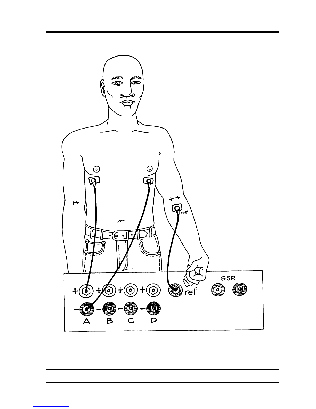
Hooking Up
Use the Heart configuration to look and listen to your heart rate change.
1. From the FILE menu choose LOAD CONFIGURATION.
2. Select HEART.CFG.
3. Connect the electrodes as in the diagram. Use the disposable electrodes and lead wires
provided.
4. Turn the WaveRider on by clicking the ON
button with your mouse or by using “Ctrl” +
“o”.
5. The heart strip chart should have a clean signal if the electrodes are properly connected.
Copyright 1997-2004 Jonathan Purcell
All Rights Reserved
62

WaveRider Operating Manual
63
Copyright 1997-2004 Jonathan Purcell
All Rights Reserved

WaveRider Operating Manual
CHANNELS USED FOR HEART MODE VARY BETWEEN MODELS AND MAY
DIFFER FROM WHAT IS SHOWN
Copyright 1997-2004 Jonathan Purcell
All Rights Reserved
64

WaveRider Operating Manual
THINGS TO TRY
Questions
• Which will lower your heart rate more, deep breathing or shallow breathing.
• What effect does caffiene, sugar or alcohol have on your heart rate.
• What happens if you think about your lover, an academic test or your financial situation?
• Try measuring your heart rate before exercise, immediately after exercise and half an hour
after exercise.
• What happens to your heart rate after you make love?
• What happens to your heart rate before during and after you smoke a cigarette? After you
quit smoking?
• What happens to your heart rate when you watch a horror or action movie?
• Measure the heart rate of some friends. Talk before hand about who will have the highest
and lowest heart rate.
• Discuss the results
65
Copyright 1997-2004 Jonathan Purcell
All Rights Reserved

WaveRider Operating Manual
Copyright 1997-2004 Jonathan Purcell
All Rights Reserved
66

WaveRider Operating Manual
MUSCLE
Configuration File: MUSCLE
Use Category: MUSCLE
Use the muscle configuration to:
• relax or
• play music with your muscles.
When you tense your muscles they produce an envelope of broadband electrical activity that
ranges from 20 to 1000 hertz. The WaveRider measures this envelope of electrical output
and allows you to output it graphically or as sound.
Hooking Up
1. From the FILE menu choose LOAD CONFIGURATION.
2. Select MUSCLE.CFG.
3. Connect the electrodes as in the diagrams, or put them on a different set of muscle
groups. Use the disposable electrodes and lead wires provided.
4. Turn the WaveRider on by clicking the ON
button with your mouse or by using ""Ctrl O."
5. The muscle strip chart should have a clean signal if the electrodes are properly connected.
6. Flex or relax your muscles
67
Copyright 1997-2004 Jonathan Purcell
All Rights Reserved

WaveRider Operating Manual
Copyright 1997-2004 Jonathan Purcell
All Rights Reserved
68

WaveRider Operating Manual
69
Copyright 1997-2004 Jonathan Purcell
All Rights Reserved

WaveRider Operating Manual
Things to Try
If you are using the muscle configuration to play music, try setting different threshold levels
so that you can create periods of silence and noise.
If you are using the muscle configuration to train relaxation you may need to raise the
sensitivity.
Try relaxing to get the sound to go down.
Think about something stessful and notice the response you get.
Copyright 1997-2004 Jonathan Purcell
All Rights Reserved
70

WaveRider Operating Manual
Adjustable Parameters
To change the audio output, double click on the MIDI window with your mouse. The dialog
box pictured above will be displayed. You can test the effects of your changes by clicking
APPLY. When you are satisfied hit OK.
If it is too easy to get over the threshold (make the music start):
Make the lower number in Amplitude Range (uV) (currently 35) higher.
If it is too hard to get over the threshold (make the music start):
Make the lower number in Amplitude Range (uV) (currently 35) lower.
If you hit the high note too easily:
Make the higher number in Amplitude Range (uV) (currently 140) higher.
If you don't have a large enough range of notes:
Make the range of notes (currently 48-72) wider.
If you want the tone to get lower instead of higher:
Reverse the Note numbers.
71
Copyright 1997-2004 Jonathan Purcell
All Rights Reserved

WaveRider Operating Manual
RELAX
You can use the WaveRider to play with your alpha waves.
Many people in todays' overstressed world have difficulty relaxing or letting go. Alpha
waves provide a way to relax deeply and also a way to relax while remaining attentive.
You can produce alpha waves by closing your eyes and relaxing. Some people report that
they produce alpha with their eyes closed after they have "given up," or let go of their ego.
When they have ceased to try.
Alpha wave rhythms are generated deep in the brain in the thalamus. They are radiated to the
cerebral cortex. There tends to be a lot of alpha generated in the occipital lobe in the back of
the head when the eyes are closed.
Most people can generate alpha without too much effort. Usually this comes as alpha flares
or short burst of alpha. Once you get good at producing alpha, try to maintain a consistent
level. Also, try to purposefully change your level of alpha.
The following lessons will show you a number of ways to play with alpha waves:
You can learn to relax yet remain attentive.
You can learn to relax more fully.
You can learn to clear your mind.
You can validate other forms of relaxation.
Copyright 1997-2004 Jonathan Purcell
All Rights Reserved
72

WaveRider Operating Manual
PER CENT ALPHA
Closed Eye Relaxation
Configuration File: %ALPHA
Use Category: BRAIN
Per Cent Alpha uses the ratio of alpha waves to the entire brainwave spectrum to train
relaxation.
You can use Per Cent Alpha to:
• relax
• adjust your reaction to stress
• guide yourself into an egoless state of mind
HOOKING UP
Use the PER CENT ALPHA configuration to use your brainwaves to relax.
1. From the FILE menu choose LOAD CONFIGURATION.
2. Select %ALPHA.CFG.
3. Connect the electrodes as in the diagram. Use the cup electrodes supplied and the ten-20
paste. Make sure that the skin is clean and you have a good contact.
4. Turn the WaveRider on by clicking the ON
button with your mouse or by using “Ctrl” +
“o”.
5. The brain strip chart should have a clean signal if the electrodes are properly connected.
6. Close your eyes. Relax. Drop your shoulders. Make the note go up.
Close your eyes
Drop your shoulders
Take a few deep breaths
Clear your mind
Let go
73
Copyright 1997-2004 Jonathan Purcell
All Rights Reserved

WaveRider Operating Manual
Copyright 1997-2004 Jonathan Purcell
All Rights Reserved
74

WaveRider Operating Manual
Questions?
What can you do to produce alpha?
If you think about different colors does it help you to produce alpha?
Are there body positions in which you are more able to produce alpha?
Are there parts of your body that you can think about that will help you to produce alpha?
Your shoulders? The top of your head? The Space between your ears?
Can you do it with your eyes open?
What makes you go into alpha reliably?
What makes you leave alpha reliably?
75
Copyright 1997-2004 Jonathan Purcell
All Rights Reserved

WaveRider Operating Manual
Adjustable Parameters
To change the audio output, double click on the MIDI window with your mouse. The dialog
box pictured above will be displayed. You can test the effects of your changes by clicking
APPLY. When you are satisfied hit OK.
If it is too easy to get over the threshold (make the music start):
Make the lower number in % Ratio A/B (currently 32) higher.
If it is too hard to get over the threshold (make the music start):
Make the lower number in % Ratio A/B (currently 32) lower.
If you hit the high note too easily.
Make the higher number in % Ratio A/B (currently 50) higher.
If you don't have a large enough range of notes.
Make the range of notes (currently 60-72) wider or lower the the higher number in
% Ratio A/B (currently 50).
If you want the tone to get lower instead of higher.
Reverse the Note numbers.
Copyright 1997-2004 Jonathan Purcell
All Rights Reserved
76

WaveRider Operating Manual
PER CENT HI-ALPHA
Open Eye Relaxation
Configuration File: %HIALPHA
Use Category: BRAIN
Per Cent Hi-Alpha uses the ratio of Hi-alpha waves (10-13 Hertz) to the entire brainwave
spectrum (4-40 hertz) to train relaxed attentiveness.
You can use Per Cent Hi-Alpha to:
• learn a sense of presence
• quell your internal dialogue
• be alert but relaxed
HOOKING UP
Use Per Cent Hi-Alpha configuration to get a sense of relaxed attentiveness.
1. From the FILE menu choose LOAD CONFIGURATION.
2. Select %HIALPHA.CFG.
3. Connect the electrodes as in the diagram. Use the cup electrodes supplied and the ten-20
paste. Make sure that the skin is clean and you have a good contact.
4. Turn the WaveRider on by clicking the ON
button with your mouse or by using “Ctrl” +
“o”.
5. The brain strip chart should have a clean signal if the electrodes are properly connected.
6. With your eyes opened relax while remaining attentive. Drop your shoulders. Make the
note go up.
77
Copyright 1997-2004 Jonathan Purcell
All Rights Reserved

WaveRider Operating Manual
Copyright 1997-2004 Jonathan Purcell
All Rights Reserved
78

WaveRider Operating Manual
Questions?
What can you do to produce hi-alpha?
What feeling does it give you?
When do you feel like this in your daily life?
When would this feeling be useful?
Are there body positions in which you are more able to produce hi-alpha?
Can you produce hi-alpha with your eyes shut?
What makes you reliably go into hi-alpha?
What makes you reliably leave hi-alpha?
79
Copyright 1997-2004 Jonathan Purcell
All Rights Reserved

WaveRider Operating Manual
Adjustable Parameters
To change the audio output, double click on the MIDI window with your mouse. The dialog
box pictured above will be displayed. You can test the effects of your changes by clicking
APPLY. When you are satisfied hit OK.
If it is too easy to get over the threshold (make the music start):
Make the lower number in % Ratio A/B (currently 25) higher.
If it is too hard to get over the threshold (make the music start):
Make the lower number in % Ratio A/B (currently 25) lower.
If you hit the high note too easily:
Make the higher number in % Ratio A/B (currently 50) higher.
If you don't have a large enough range of notes:
Make the range of notes (currently 60-72) wider or lower the
higher number in % Ratio A/B (currently 50).
If you want the tone to get lower instead of higher:
Reverse the Note numbers.
Copyright 1997-2004 Jonathan Purcell
All Rights Reserved
80

WaveRider Operating Manual
ALPHA AMPLITUDE
Closed Eye Relaxation
Configuration File: ALPHAMP
Use Category: BRAIN
Alpha Amplitude uses the alpha waves to train relaxation.
You can use the Alpha Amplitude to:
• relax
• adjust your reaction to stress
• guide yourself into an egoless state of mind
HOOKING UP
Use the Alpha Amplitude configuration to use your brainwaves to relax.
1. From the FILE menu choose LOAD CONFIGURATION.
2. Select ALFAMP.CFG.
3. Connect the electrodes as in the diagram. Use the cup electrodes supplied and the ten-20
paste. Make sure that the skin is clean and you have a good contact.
4. Turn the WaveRider on by clicking the ON
button with your mouse or by using “Ctrl” +
“o”.
5. The brain strip chart should have a clean signal if the electrodes are properly connected.
Close your eyes
Drop your shoulders
Take a few deep breaths
Clear your mind
Let go
81
Copyright 1997-2004 Jonathan Purcell
All Rights Reserved

WaveRider Operating Manual
Copyright 1997-2004 Jonathan Purcell
All Rights Reserved
82

WaveRider Operating Manual
Questions?
What can you do to produce alpha?
If you think about different colors does it help you to produce alpha?
Are there body positions in which you are more able to produce alpha?
Are there parts of your body that you can think about that will help you to produce alpha?
Your shoulders? the top of your head?
Can you do it with your eyes open?
What makes you reliably go into alpha?
What makes you reliably leave alpha?
83
Copyright 1997-2004 Jonathan Purcell
All Rights Reserved

WaveRider Operating Manual
Adjustable Parameters
To change the audio output, double click on the MIDI window with your mouse. The dialog
box pictured above will be displayed. You can test the effects of your changes by clicking
APPLY. When you are satisfied hit OK.
If it is too easy to get over the threshold (make the music start):
Make the lower number in Range (uV) (currently 10.0) higher.
If it is too hard to get over the threshold (make the music start):
Make the lower number in Range (uV) (currently 10.0) lower.
If you hit the high note too easily.
Make the higher number in Range (uV) (currently 18.0) higher.
If you don't have a large enough range of notes.
Make the range of notes (currently 60-72) wider.
If you want the tone to get lower instead of higher.
Reverse the Note numbers.
Copyright 1997-2004 Jonathan Purcell
All Rights Reserved
84

WaveRider Operating Manual
GSR / % ALPHA
Deep Relaxation
Configuration File: GSR-ALPH
Use Category: BRAIN GSR
GSR/% Alpha combines the GSR mode for relaxation of the autonomic nervous system with
closed eye brainwave relaxation. It is especially good for getting into deep relaxation.
HOOKING UP
Use the GSR/%Alpha configuration to deeply relax.
1. From the FILE menu choose LOAD CONFIGURATION.
2. Select GSR-Alph.CFG.
3. Connect the electrodes as in the diagram. Use the cup electrodes supplied and the ten-
20 paste for the brain electrodes. Make sure that the skin is clean and you have a good
contact. Use no paste with the GSR electrodes.
4. Turn the WaveRider on by clicking the ON
button with your mouse or by using ""Ctrl
O."
5. The brain strip chart should have a clean signal if the electrodes are properly connected.
6. Close your eyes. Relax. Drop your shoulders. Make the notes go lower.
7. The GSR (oboe sound) will react slowly.
85
Copyright 1997-2004 Jonathan Purcell
All Rights Reserved

WaveRider Operating Manual
Copyright 1997-2004 Jonathan Purcell
All Rights Reserved
86

WaveRider Operating Manual
Things to Do
Close your eyes.
Breathe deeply.
Drop your shoulders.
Make the note get lower.
You should get so relaxed that your chin falls on your chest.
Be sure to adjust the GSR for your readings.
87
Copyright 1997-2004 Jonathan Purcell
All Rights Reserved

WaveRider Operating Manual
Adjustable Parameters
The GSR uses dynamic offset adjustment and provides different levels of resolution.
You may need to use the COPY FROM GSR CHART button in the the MIDI
Options dialog box and the General Grapics dialog Box. This will copy the dynamically
assigned range in the GSR Window into the selected dialog box. You may also use the spin
controls in the dialog box.
Copyright 1997-2004 Jonathan Purcell
All Rights Reserved
88

WaveRider Operating Manual
ALPHA/THETA
ALPHA/THETA WITH 2 TONES
ALPHTHET.CFG
Use the alpha/theta with 2 tones configuration to learn the boundary between alpha and theta.
You can try this configuration with your eyes opened or closed.
1. From the FILE menu choose LOAD CONFIGURATION.
2. Select alphthet.cfg
3. Connect the electrodes as in the diagram. Use the cup electrodes supplied and the ten-
20 paste. Make sure that the skin is clean and you have a good contact.
4. Turn the WaveRider on by clicking the ON
“o”.
5. The brain strip chart should have a clean signal if the electrodes are properly connected.
6. The flute sound is theta and the pad is alpha. Find out what makes you switch
between these two types of brainwaves.
button with your mouse or by using “Ctrl” +
89
Copyright 1997-2004 Jonathan Purcell
All Rights Reserved

WaveRider Operating Manual
Copyright 1997-2004 Jonathan Purcell
All Rights Reserved
90

WaveRider Operating Manual
Adjustable Parameters
To change the audio output, double click on the MIDI window with your mouse. The dialog
box pictured above will be displayed. You can test the effects of your changes by clicking
APPLY. When you are satisfied hit OK.
If it is too easy to get over the threshold (make the music start):
Make the lower number in Range (uV) (currently 10) higher.
If it is too hard to get over the threshold (make the music start):
Make the lower number in Range (uV) (currently 10) lower.
If you hit the high note too easily.
Make the hihger number in Range (uV) (currently 30) higher.
If you don't have a large enough range of notes.
Make the range of notes (currently 48-72) wider or lower the the higher number in
Range (uV) (currently 30).
If you want the tone to get lower instead of higher.
Reverse the Note numbers.
91
Copyright 1997-2004 Jonathan Purcell
All Rights Reserved

WaveRider Operating Manual
Copyright 1997-2004 Jonathan Purcell
All Rights Reserved
92

WaveRider Operating Manual
ALPHA/THETA FOR 2 CHANNELS
A-T-2CH.CFG
Use the alpha/theta for 2 channels configuration to evaluate the levels of Alpha and Theta on
both sides of the brain.
1. From the FILE menu choose LOAD CONFIGURATION.
2. Select A-T-2ch.Cfg.
3. Connect the electrodes as in the diagram. Use the cup electrodes supplied and the ten-
20 paste. Make sure that the skin is clean and you have a good contact.
4. Turn the WaveRider on by clicking the ON
button with your mouse or by “Ctrl” + “o”.
5. Both brain strip charts should have a clean signal if the electrodes are properly
connected.
93
Copyright 1997-2004 Jonathan Purcell
All Rights Reserved

WaveRider Operating Manual
Copyright 1997-2004 Jonathan Purcell
All Rights Reserved
94

WaveRider Operating Manual
95
Copyright 1997-2004 Jonathan Purcell
All Rights Reserved

WaveRider Operating Manual
FOCUS
Use the WaveRider to learn how to improve concentration.
The concentration exercises that follow should be thought of as a starting point. Settings
should be adjusted to accomodate individuals.
Increasing the power in higher frequency brainwave bands and decreasing power in lower
frequency bands can improve concentration and attention. The higher range frequencies may
include: 12-15 Hertz (SMR), 15-18 Hertz (Beta), 14 Hertz, 16-21 Hertz and 12-22 Hertze
etc. Lower frequency bands may include 4-8 Hertz, 2-6 Hertz, 2-7 Hertz, 5-8 Hertz etc.
There are a variety of opinions on the efficacy of different protocols as there are on electrode
placements.
BETA/THETA trains the increase of BETA (15-18 Hertz) and the decrease of Theta.
SMR/THETA trains the increase of SMR (12-15 Hertz) and the decrease of Theta.
THETA SUPPRESS simply suppresses Theta.
Copyright 1997-2004 Jonathan Purcell
All Rights Reserved
96

WaveRider Operating Manual
BETA/THETA
Open Eye Concentration
Configuration File: BET-THET
Use Category: BRAIN
This configuration uses an increase of Beta and decrease of Theta to train concentration.
You can use BETA/THETA to:
• learn to concentrate better
• learn to pay attention
• be alert
HOOKING UP
Use BETA/THETA configuration to get a sense of concentration.
1. From the FILE menu choose LOAD CONFIGURATION.
2. Select BET-THET.CFG.
3. Connect the electrodes as in the diagram. Use the cup electrodes supplied and the ten-
20 paste. Make sure that the skin is clean and you have a good contact.
4. Turn the WaveRider on by clicking the ON
button with your mouse or by “Ctrl” + “o”.
5. The brain strip chart should have a clean signal if the electrodes are properly connected.
6. With your eyes opened focus your attention. Make the note go up.
97
Copyright 1997-2004 Jonathan Purcell
All Rights Reserved

WaveRider Operating Manual
Copyright 1997-2004 Jonathan Purcell
All Rights Reserved
98

WaveRider Operating Manual
THINGS TO TRY
Read a book.
Look at the details in an intricate piece of artwork.
Do something that is interesting to you.
Listen to a person or tape that has a lot of information.
QUESTIONS
What do you have to do to change the tone?
What feeling does this give you?
Can you reproduce this feeling without the WaveRider?
When would it be appropriate to have this mental attitude?
When would it be inappropriate?
In a Group
Who will be able to most consistently focus?
Who will be able to focus the longest?
What does it feel like when you focus?
When can this mental attitude help you?
99
Copyright 1997-2004 Jonathan Purcell
All Rights Reserved

WaveRider Operating Manual
Beta/Theta makes use of the Reward Suppress Using Filters algorithm. This algorithm
ouputs a range of notes based on a range of ratios of two frequency bands. The output only
occurs though, if certain threshold conditions are met.
In this case:
If Beta is above 2.0 microVolts
And Theta is below 7.0 microVolts
And Delta (1.5-4 hertz) is below 20 microVolts,
Then the ratio of Beta to theta from 60 to 130 percent will be mapped to MIDI notes 60
(middle C) to 84 (the C two octaves above middle C).
If the ratio goes below the threshold of 60 per cent or above 130 per cent no audio will be
output.
To modify these thresholds, first observe the Beta, Theta and Delta General Graphics
Windows to the left.
Copyright 1997-2004 Jonathan Purcell
All Rights Reserved
100
 Loading...