

Page 1
MP83xx Image Platform Quick Guide
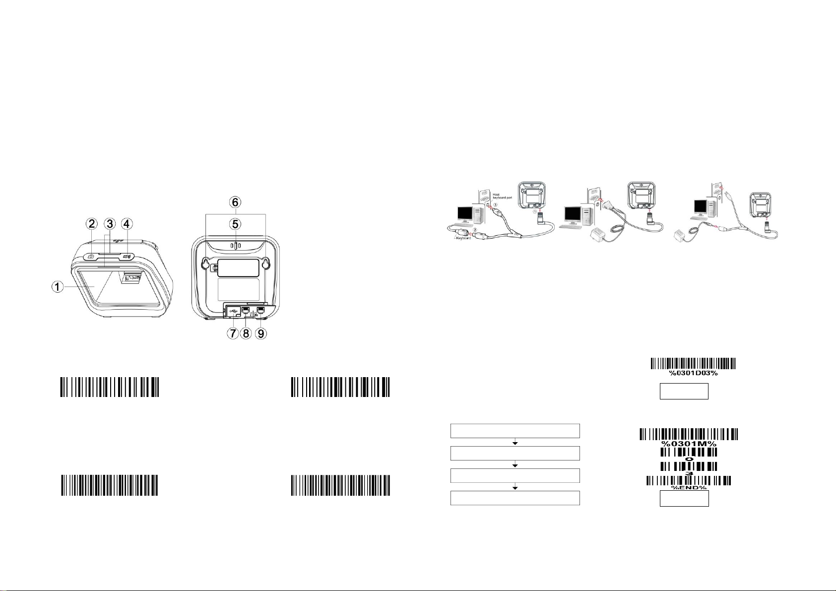
① Exit window
② Camera push button
③ LED
④ Beeper push button
⑤ Beeper
⑥ Hanging holes
⑦ USB interface
⑧ Auxiliary interface for
handheld scanner, etc
⑨ Host interface
Default value initialization
Firmware version list
Timeout off (Default)
Good-read off
PS2 cable
RS232 cable
USB cable
Scan the appropriate barcode on
the right.
Example: to set Flow control to be XON/XOFF.
Scan “Option bar code”
Scan “The 1st character of option”
Scan “The 2nd character of option”
Scan “END”
Example: to set Flow control to be XON/XOFF.
A standard packing includes an image platform, a 5V adaptor, a USB cable and a
CD (or a user manual).
Accessories include a stand, a RS232 cable and a PS2 cable.
Use a piece of dry and soft cloth when cleaning the image platform is in need.
Installing the cable
Notice
Parts of the scanner
Returning default parameters and listing version information
1. Switch off the host system.
2. Refer to the below pictures, connect the host with the image platform based on different
cables.
3. Ensure that all connections are secure.
4. Switch on the host system. If the installation is successful, the beeper will beep and LED
will light.
Programming instruction and example
Two programming modes have been provided as bellows:
Single-scan setting
Scan mode (Alternative)
Note: 1. More details refer to User Manual. 2. For better readability, please print this document with laser printer. 3. Version: MP83xx_QG_EN_V1.1.
Multiple-scan setting
Page 2
Reading techniques
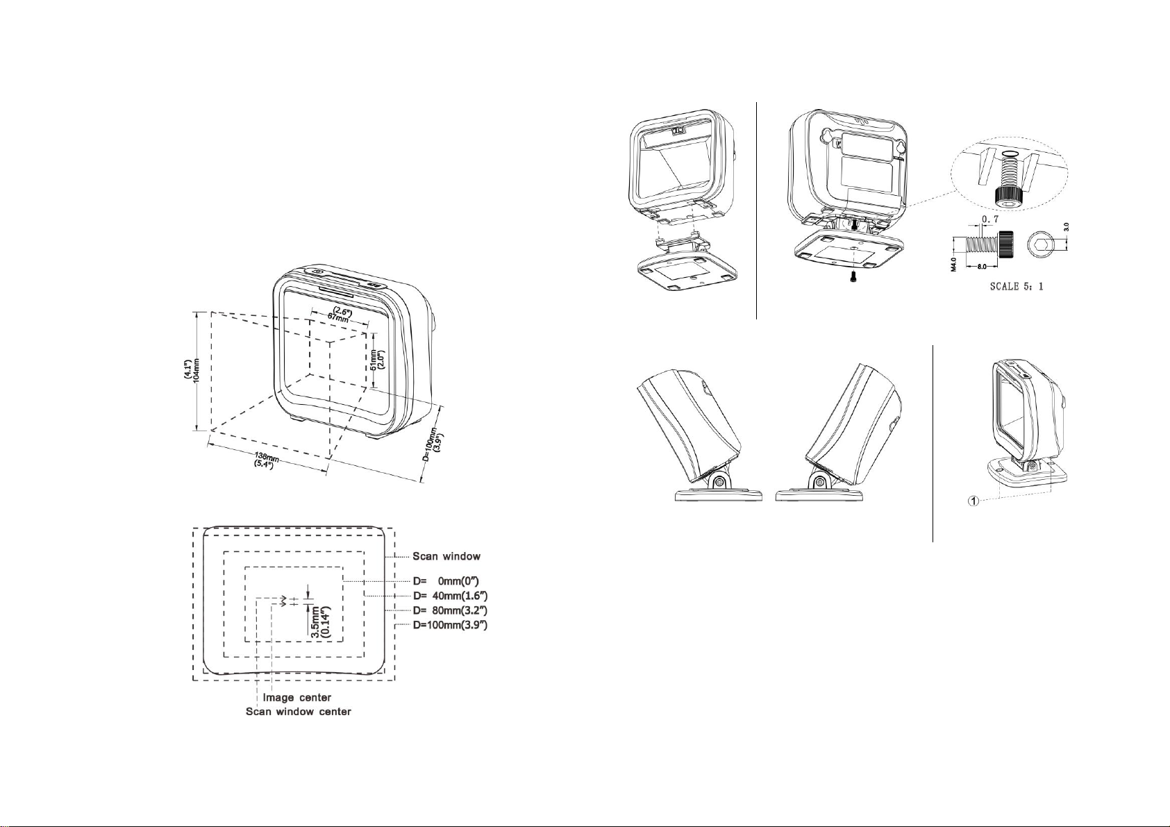
Figure 1 Field of view
Figure 2 Field of view – Front view
Figure 3
Figure 4
Figure 5
Figure 6
1. Move the barcode to close to the image platform.
2. In general, the reading range of the image platform is limited to 2-8cm regardless of the
size of the minimal element of the barcode.
3. On a successful reading, the beeper will beep and the LED will light. If no barcode closes
to the image platform in a moment, the image platform will go to sleep.
Field of view
Assembling the stand
Note: 1. More details refer to User Manual. 2. For better readability, please print this document with laser printer. 3. Version: MP83xx_QG_EN_V1.1.
1. As shown in Figure 3, plug in two connection-arms to the two associated notches on the
bottom of the image platform.
2. As shown in Figure 4, well connect the image platform with the stand by tightening the
single screw.
3. As shown in Figure 5, adjust the image platform forward/backward for a desired position.
4. As shown in Figure 6, if you want to fix the stand on a table or other platform, you can
remove two plastic stopper on the stand (see ①), then fix the stand with a table with
appropriate screws.
 Loading...