

Page 1
FS580 Industrial Fixed Laser Barcode Scanner
User Manual
Version: FS580_UM_EN_V1.1.6
Page 2

Page 3

i
Notice
Make sure you carefully read the following information to ensure that your barcode scanner is able to
perform at the designed level.
1. All software, including firmware, furnished to the user is on a licensed basis.
2. The right is reserved to make changes to any software or product to improve reliability, function, or
design.
3. The material in this manual is subject to change without notice. Please go to www.mindeo.cn for
latest service information.
4. The manufacturer assumes no responsibility for any loss or claim by third parties which may arise
from the use of this manual.
5. Do not throw or drop the scanner or subject it to strong impact. Otherwise that can damage the
scanner, interrupt program execution, corrupt memory contents, or interfere with proper operation.
6. Please do keep exit window clean, otherwise it may cause that the scanner decodes incorrectly or
fails to read the barcode.
Page 4

ii
Notes about structure and electric circuit design
1. Use non-magnetic screws, or locating pins when mounting the scanner. Magnetic screws or locating
pins can cause element/mirror central position to change.
2. It is recommended to use a thread locking method, such as a Nylok patch.
3. It is not recommended to place magnetic material (e.g. dynamic speakers, ringers, vibrators,
inductors, metal parts) within 1 inch of the scanner’s optics. Evaluate placement of all magnetic or
ferrous material during system layout to determine if 1 inch is sufficient. Please read section
“3-1
Important notes of installation”
for detail.
4. Leave sufficient space to accommodate the maximum size of the scanner.
5. Read section
“2-1 Electrical interface/Pin assignment”
carefully to learn about the electrical interface
design.
6. Read section
“2-2 Power management”
carefully to learn about the two power states.
7. Read section
“3-4 Scan angle”
carefully to learn about the scan angle of the scanner.
8. Do not hold the scanner vertically over the bar code. Please refer to section
“3-5 Tilt angle and dead
zone”
for details.
9. Refer to section
“5-13 PARAM_SEND”
, be noted that frequent permanent changes of parameter
value are not recommended due to the limited write-cycles of flash memory. It is recommended to
change parameter temporarily, if frequently modifying parameter is a must.
10. Read section
“6-4 SCI transactions notes”
carefully.
Page 5

iii
Contents
Notice ...................................................................................................................................................... i
Notes about structure and electric circuit design ..................................................................................... ii
1 Specifications ..................................................................................................................................... 1
1-1 Technical specifications .............................................................................................................. 1
1-2 Default settings for various types of barcode .............................................................................. 3
1-3 Decode zone ............................................................................................................................... 4
2 Get started ......................................................................................................................................... 5
2-1 Electrical interface/Pin assignment ............................................................................................. 5
2-2 Power management .................................................................................................................... 6
3 Installation guide ................................................................................................................................ 7
3-1 Notes of installation ..................................................................................................................... 7
3-2 Mounting ..................................................................................................................................... 8
3-3 Appearance of the scanner ......................................................................................................... 9
3-4 Scan angle ................................................................................................................................ 10
3-5 Tilt angle and dead zone ........................................................................................................... 11
4 Parameter menus ..............................................................................................................................12
4-1 Introduction ............................................................................................................................... 12
4-2 Example: configure scanner ...................................................................................................... 13
4-3 RS232 interface ........................................................................................................................ 15
4-4 USB interface ............................................................................................................................ 18
4-5 Scan mode & some global settings ........................................................................................... 21
4-6 Indication ................................................................................................................................... 27
4-7 UPC-A ....................................................................................................................................... 28
4-8 UPC-E ....................................................................................................................................... 30
4-9 UPC-E1 ..................................................................................................................................... 32
4-10 EAN-13 (ISBN/ISSN) .............................................................................................................. 34
4-11 EAN-8 ..................................................................................................................................... 36
4-12 Code 39 (Code 32, Trioptic Code 39) ..................................................................................... 38
4-13 Interleaved 2 of 5 .................................................................................................................... 41
4-14 Industrial 2 of 5........................................................................................................................ 43
4-15 Matrix 2 of 5 ............................................................................................................................ 44
4-16 Codabar .................................................................................................................................. 46
4-17 Code 128 ................................................................................................................................ 48
4-18 UCC/EAN 128 ......................................................................................................................... 50
4-19 ISBT 128 ................................................................................................................................. 52
4-20 Code 93 .................................................................................................................................. 54
4-21 Code 11 .................................................................................................................................. 56
4-22 MSI/Plessey ............................................................................................................................ 58
Page 6

iv
4-23 UK/Plessey ............................................................................................................................. 60
4-24 China Post .............................................................................................................................. 62
4-25 GS1 DataBar (GS1 DataBar Truncated) ................................................................................. 63
4-26 GS1 DataBar Limited .............................................................................................................. 64
4-27 GS1 DataBar Expanded .......................................................................................................... 65
4-28 G1-G4 & FN1 substitution string setting .................................................................................. 66
4-29 G1-G4 string position & Code ID position ............................................................................... 70
4-30 String transmission .................................................................................................................. 71
5 Serial Communication Interface .........................................................................................................73
5-1 SCI message formats ................................................................................................................ 74
5-2 BEEP ........................................................................................................................................ 75
5-3 CMD_ACK ................................................................................................................................. 77
5-4 CMD_NAK ................................................................................................................................. 78
5-5 DECODE_DATA ....................................................................................................................... 80
5-6 LED_CTR .................................................................................................................................. 81
5-7 REQUEST_REVISION .............................................................................................................. 82
5-8 REPLY_REVISION ................................................................................................................... 83
5-9 START_DECODE ..................................................................................................................... 84
5-10 STOP_DECODE ..................................................................................................................... 85
5-11 PARAM_DEFAULTS ............................................................................................................... 86
5-12 PARAM_REQUEST ................................................................................................................ 87
5-13 PARAM_SEND ........................................................................................................................ 89
5-14 CUSTOM_DEFAULTS ............................................................................................................ 92
5-15 WAKEUP ................................................................................................................................ 93
5-16 CMD_RESTART ..................................................................................................................... 94
5-17 CMD_OUTPUTBUFFER_CTR ................................................................................................ 95
6 SCI transactions ................................................................................................................................96
6-1 ACK/NAK handshaking ............................................................................................................. 96
6-2 Transfer of decode data ............................................................................................................ 97
6-3 Transaction examples ............................................................................................................... 98
6-4 SCI transactions notes ............................................................................................................ 101
7 Glossary .......................................................................................................................................... 102
8 Barcode representing non-printable character ................................................................................. 103
9 ASCII table ...................................................................................................................................... 104
10 Test chart ...................................................................................................................................... 105
11 Return default parameters & firmware version ............................................................................... 107
12 Configuration alphanumeric value barcode (as Para. value) .......................................................... 108
Page 7

1
1 Specifications
1-1 Technical specifications
Table 1-1 Technical specifications @25°C
Item
Description
Input voltage
5 VDC ± 5%
Scanning current
RS232: 145mA (Typ.) / 235mA (Max.)
USB: 145mA (Typ.) / 220mA (Max.)
Standby current
RS232: 0.9mA(Deep Sleep) or 25mA
USB: 30mA
Laser
650nm laser diode
Scan rate
100±10 scans/second
Scanning angle
Wide (Default): 55°±5°, decode rate: 0.5 time/scan
Narrow: 40°±5°, decode rate: 1 time/scan
Pitch angle
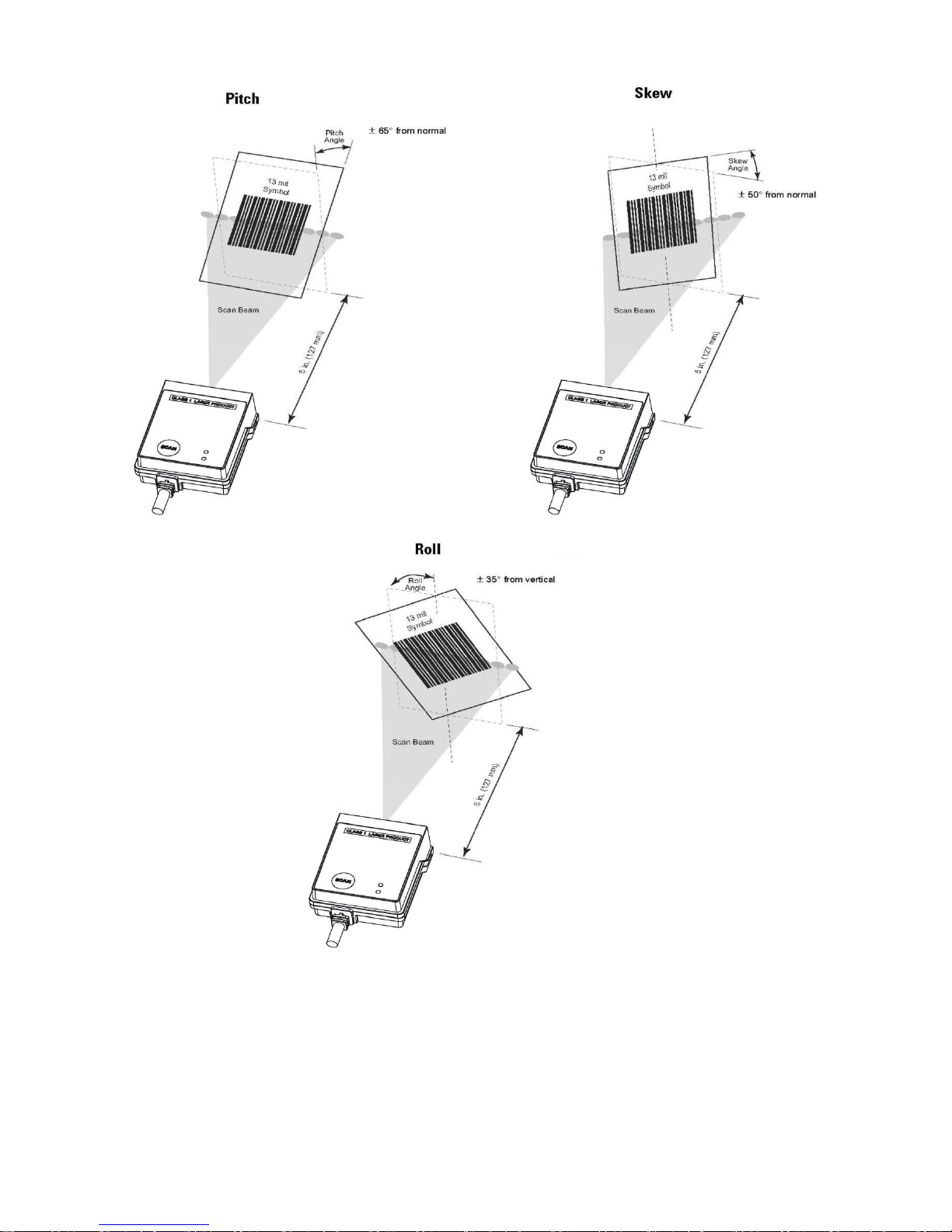
±65° (Condition: 100% UPC at 5 in. See Figure 1-1 )
Skew angle
±50° (Condition: 100% UPC at 5 in. See Figure 1-1 )
Roll angle
±35° (Condition: 100% UPC at 5 in. See Figure 1-1)
Decode capability
UPC-A, UPC-E, UPC-E1, EAN-13, EAN-8, ISBN/ISSN, Code 39, Code 39 full
ASCII, Code 32, Trioptic Code 39, Interleaved 2 of 5, Industrial 2 of 5 (Discrete
2 of 5), Matrix 2 of 5, Codabar (NW7), Code 128, Code 93, Code 11 (USD-8),
MSI/Plessey, UK/Plessey, UCC/EAN 128, ISBT128,China Post, GS1 DataBar
(formerly RSS) variants
Indicator
Beeper, LED
Interface supported
RS232, USB Keyboard, USB virtual COM
Scan mode
Single scan, Continuous scan, Auto-detection, Scan Output Buffering,
Command
Housing makings
Zinc alloy
Dimensions
Height× Width ×Depth: 35.7mm × 41.3mm × 17.2mm (maximum)
Weight
70g
Cable
RJ-45
Temperature
Operating: -10°C to 60°C (-4°F to 140°F);
Storage: -40°C to 70°C (-40°F to 158°F)
Humidity
5% to 90% (non-condensing)
Programming method
Method I: Manual (scanning special barcode in sequence)
Method II: Send command via RS232 interface or USB virtual COM
Firmware upgrade
Online
Decoding depth
& Max. resolution
(1 mil = 0.0254 mm)
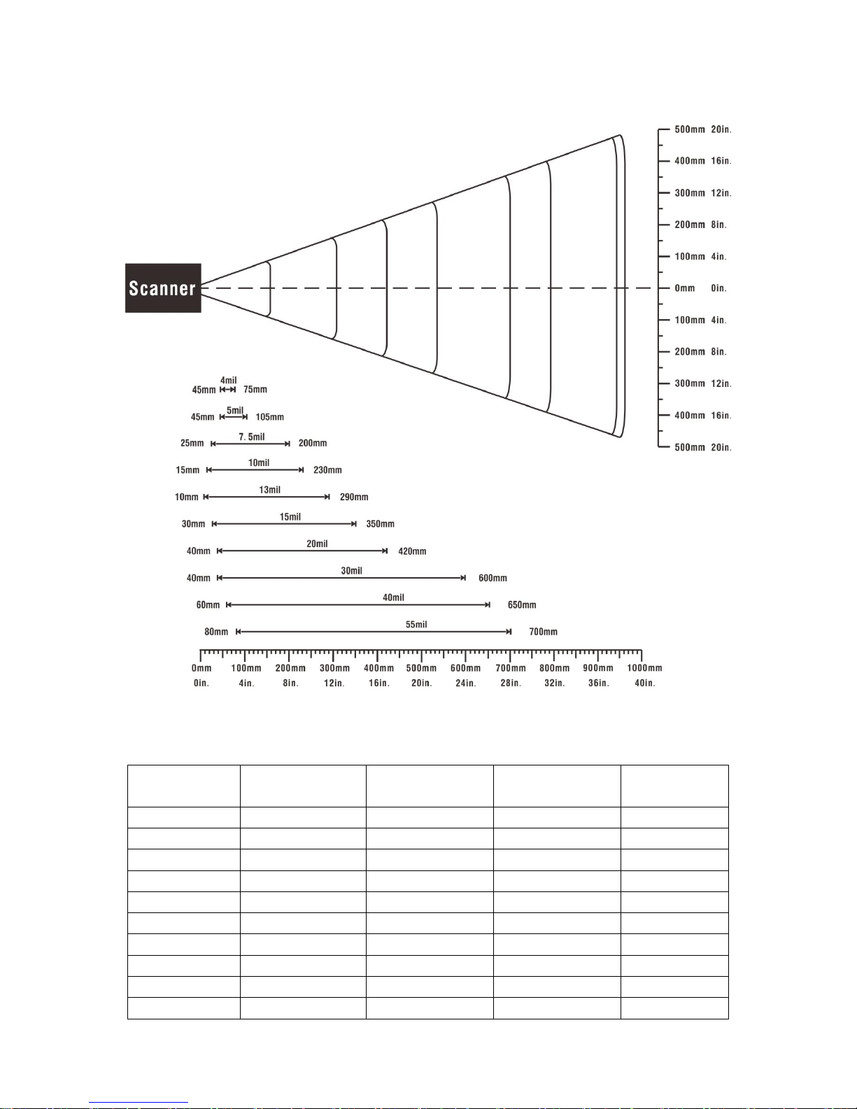
4 mil: 45- 75 mm
5 mil: 45-105 mm
10 mil: 15-230 mm
15 mil: 30-350 mm
20 mil: 40-420 mm
30 mil: 40-600 mm
55 mil: 80-700 mm
See section “1-3 Decode zone ” for more information.
Safety and Certification
Laser safety:EN60825-1,Class 1
EMC:EN55022,EN55024
Protection class:IP64
Page 8
2
Figure 1-1 Pitch, Skew and Roll
Page 9

3
1-2 Default settings for various types of barcode
Table 1-2 Default settings
Code type
Read
enable
Check digit
verification
Check digit
transmission
Min. code
length
Proprietary
code ID
AIM
code ID
UPC-A
√ √ √
(12)2
A
]Em
UPC-E
√ √ √
(8)2
D
]Em
UPC-E1
√ √ √
(8)2
D
]Em
EAN-13
√ √ √
(13)2
A
]Em
EAN-8
√ √ √
(8)2
C
]Em
ISBN/ISSN1
√ √ √
(13)2
A
]Em
Code 39
√ - - 1 M
]Am
Interleaved 2 of 5
√ - - 6 I
]Im
Industrial 2 of 5
(Discrete 2 of 5)
- - - 4 H
]Im
Matrix 2 of 5
√ - - 6 X
]Im
Codabar (NW7)
√ - - 4 N
]Fm
Code 128
√ √ - 1 K
]Cm
UCC/EAN 128
√ √ - 1 K
]Cm
ISBT 128
√ √ - 1 K
]Cm
Code 93
√ √ - 1 L
]Gm
Code 11 (USD-8)
- √ - 4 V - MSI/Plessey
- - - 4 O
]Mm
UK/Plessey
√ √ - 1 U
]Mm
China Post
√ - -
(11)2
T
]Im
GS1 DataBar
√ - -
(16)2
R
]em
GS1 DataBar Truncated3
√ - -
(16)2
R
]em
GS1 DataBar Limited
√ - -
(16)2
R
]em
GS1 DataBar Expanded
√ - - 1 R
]em
Note:
1
The settings for ISBN/ISSN and EAN-13 must be the same except the code ID.
2 Fixed-length barcodes.
3The settings for GS1 DataBar Truncated and GS1 DataBar must be the same.
Page 10
4
1-3 Decode zone
Figure 1-2 Decode zone @25°C, scan angle: 55°
Table 1-3 Description of barcode patterns applied in Figure 1-2
Resolution
Barcode type
Wide-narrow
element ratio
Barcode content
Contrast
4.0 mil
Code 128
2.5:1
123456789
80%
5.0 mil
Code 39
2.5:1
123
80%
7.5 mil
Code 39
2.5:1
ABCDEF
80%
10 mil
Code 39
2.5:1
123
90%
13 mil
100% UPC
-
1234546
90%
15 mil
Code 39
2.5:1
ABCD
80%
20 mil
Code 39
2.2:1
123
80%
30 mil
Code 39
2.2:1
EF
80%
40 mil
Code 39
2.2:1
AB
80%
55 mil
Code 39
2.2:1
CD
80%
Page 11
5
2 Get started
2-1 Electrical interface/Pin assignment
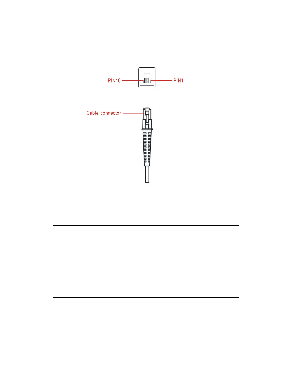
The scanner provides a RJ-45 cable connector.
Figure 2-1 Electrical interface/Pin
Table 2-1 lists the pin assignments of the scanner.
Table 2-1 Electrical interface/Pin assignment
Pin
RS232 cable
USB cable
1
Power(+5V)
Power(+5V)
2
Reserved
Reserved
3
Ground
Ground
4
+3.3V
(for interface auto selection purpose)
Ground
(for interface auto selection purpose)
5
TxD
Reserved
6
RxD
Reserved
7
Reserved
Reserved
8
Reserved
Reserved
9
CTS
D-
10
RTS
D+
Note: Voltage level of all RS232 Pin-outs (RXD, TXD, CTS and RTS) is 0V for logic low level and 3.3V
for logic high level. A transceiver (MAX232) PCB is designed inside the RS232 cable, and it can achieve
signal transition between TTL and RS232.
Page 12
6
2-2 Power management
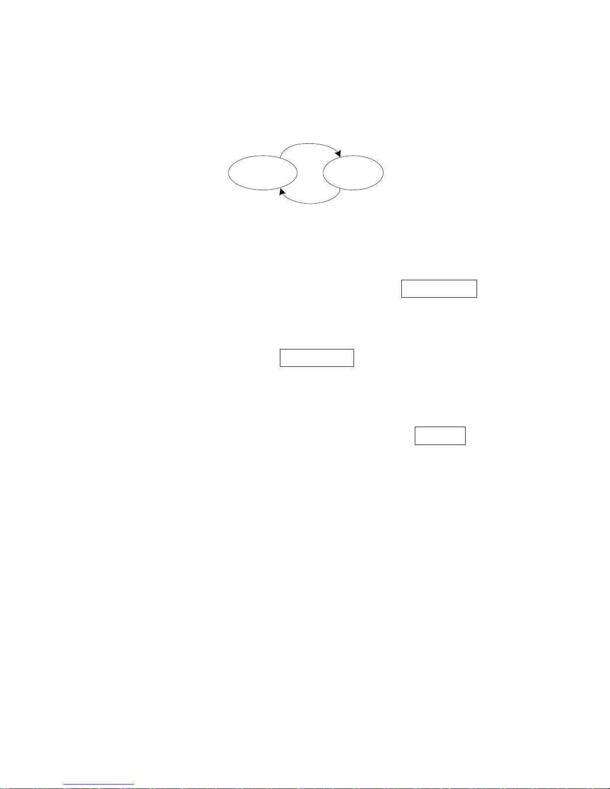
The scanner has two power states (Awake and Sleep).
Awake
State
Sleep(Deep)
State
①
②
Figure 2-2 State machine of power management
① After finishing all operation, scanner will go to Sleep state base on Auto-sleep delay(see
“4-5
Scan mode & some global settings”
), and turn off laser, swing-mirror etc.
② Interrupted event(SCAN button is pressed or falling-edge of signal RXD occurs) will make the
scanner go to Awake state.
Note: Once the scanner is awakened, at least Auto-sleep delay must elapse before it re-enters Sleep
state.
The scanner will automatically switch to the Sleep state whenever possible, so that the scanner can
consume as less current as possible. If RS232 cable is currently applied and Deep sleep(see
“4-5 Scan
mode & some global settings”
)is enabled, the scanner can enter Sleep State more deeply, and the
supply current can drop to be 0.9mA.
In other cases, the supply current in Sleep State is 25mA (RS232 cable) or 30mA (USB cable).
Page 13
7
3 Installation guide
3-1 Notes of installation
This section provides information for mounting and installing the scanner, including physical
considerations.
IP64
With IP64 approval, it is not necessary to provide extra sealing protection.
Magnetism
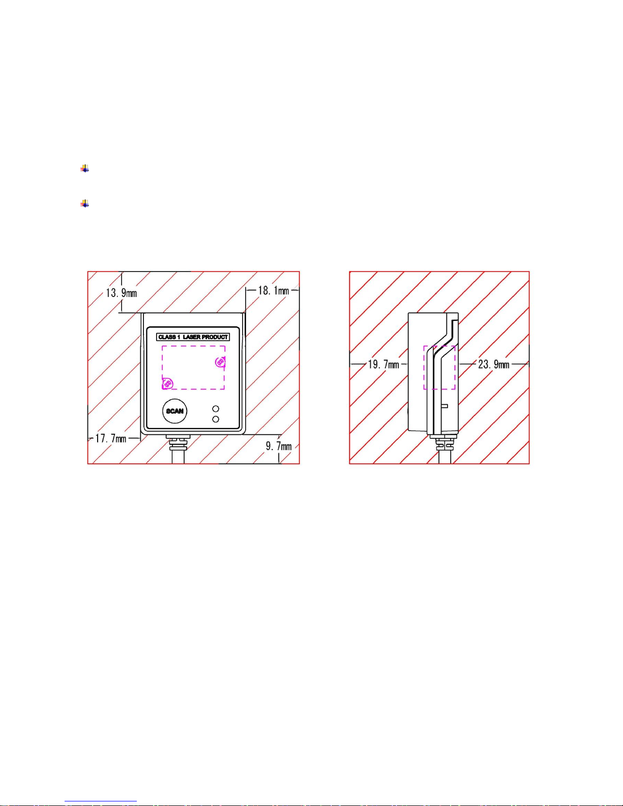
Mounting screws and locating pins should be non-magnetic material. It is not recommended to place any
magnetic material within 1 inch (2.54 cm) of the scanner’s optics without testing.
Figure 3-1 The zone without magnetic material placement
Optics
Page 14
8
3-2 Mounting
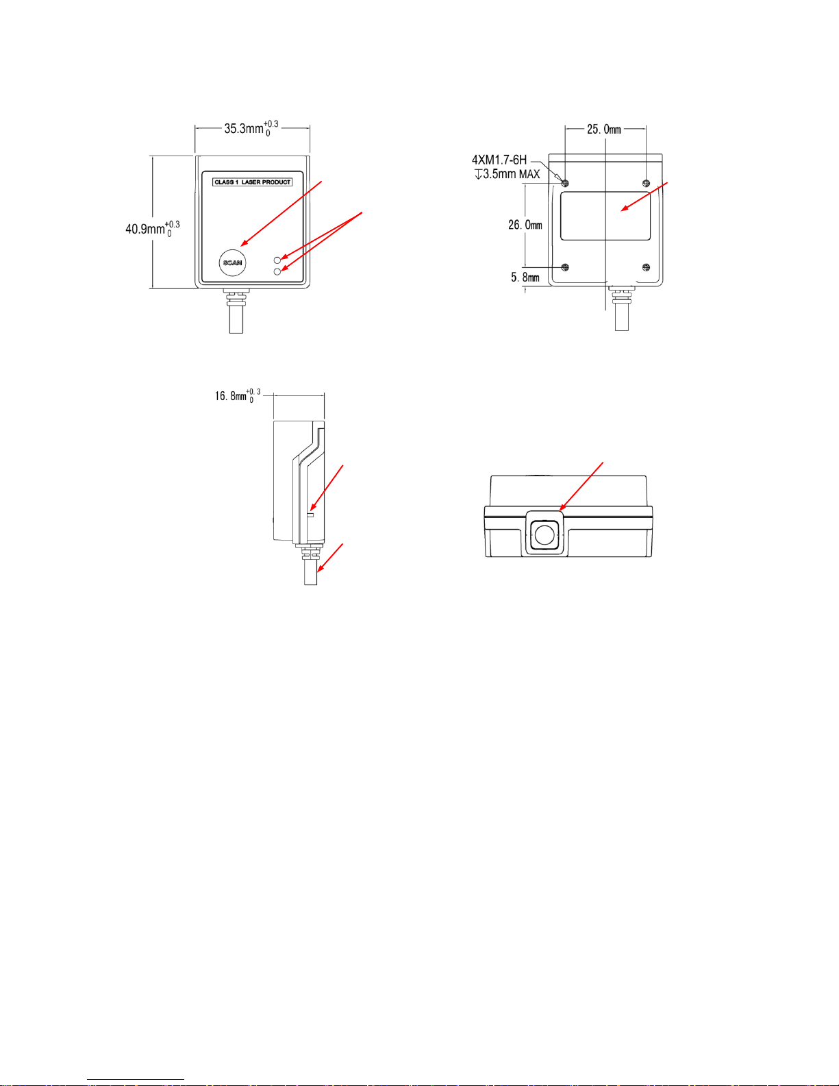
Top view
Bottom view
Side view
Back view
Figure 3-2 Mounting diagram
Notes: Mounting screws and locating pins should be non-magnetic material. It is not recommended to
place any magnetic material within 1 inch of the scanner’s optics without testing.
Button
LEDs
Label
Beeper
Cable
Cable
Page 15
9
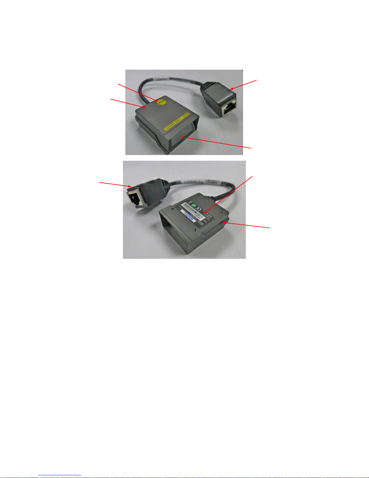
3-3 Appearance of the scanner
Figure 3-3 Appearance of the scanner
Cable
Scan Button
Laser exit window
LEDs
Cable
Beeper
Label
Page 16
10
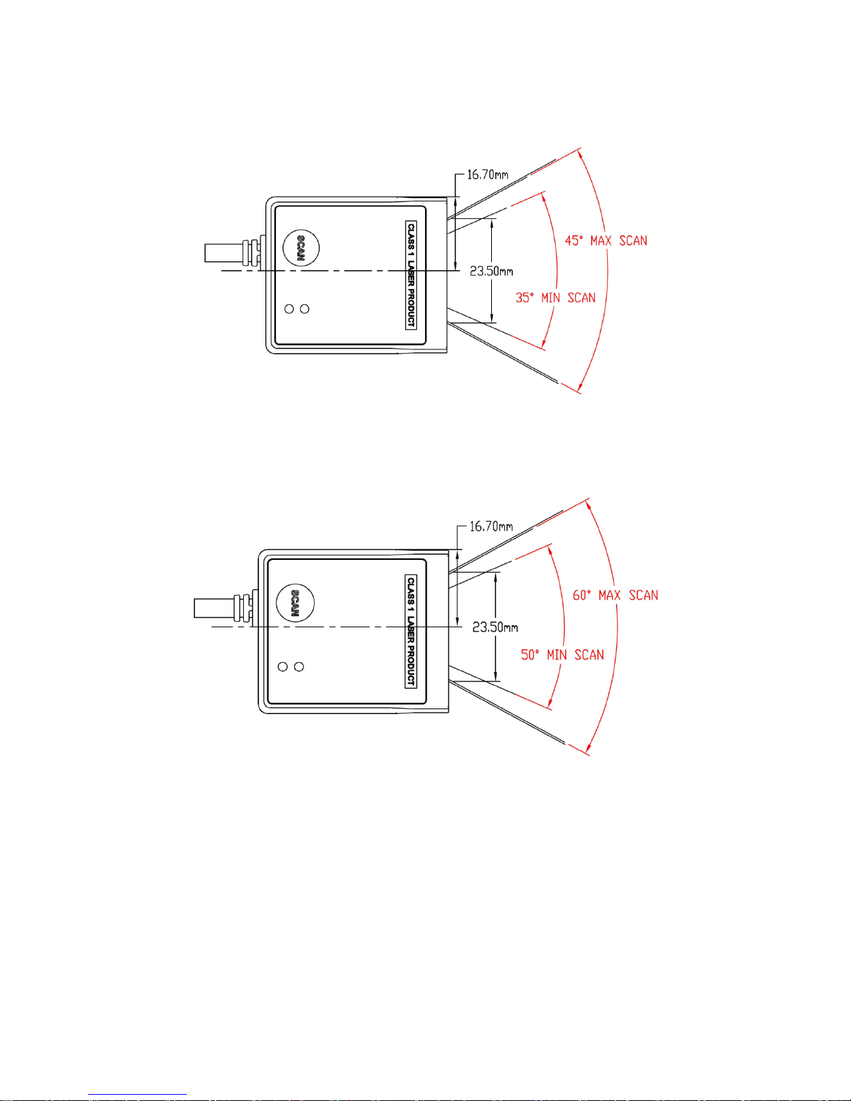
3-4 Scan angle
Scan angle (Narrow): 40°±5°
Scan angle (Wide): 55°±5°
Figure 3-4 Scan angle
Page 17
11
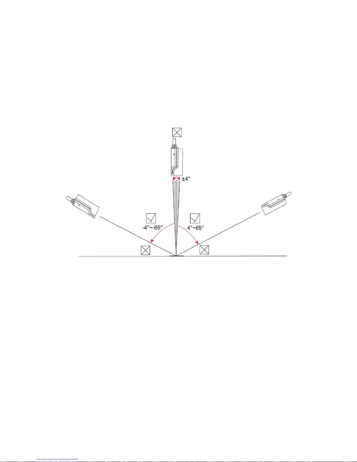
3-5 Tilt angle and dead zone
While scanning a bar code, do not hold the scanner vertically over it. This can cause the issue of
specular reflection which is the mirror-like reflection of light from a surface. In this case, the specular
refection is caused because the laser light reflects directly back into the scanner from the bar code. This
specular reflection can make decoding difficult. Tilt angle and dead zone are shown in Figure 3-5.
Figure 3-5 Tilt angle and dead zone
Page 18

12
4 Parameter menus
4-1 Introduction
This section describes the programmable parameters, provides barcodes for programming, and
hexadecimal equivalents for host parameter programming through SCI.
The scanner is shipped with the factory default settings as described in this chapter. These
factory-default-settings values are stored in flash memory and are preserved even when the scanner is
powered down. Changes to the factory default values can be stored as custom defaults. These values
are also stored in flash memory and are preserved even when the scanner is powered down.
There are two methods to change the parameter values as described following.
Scan the appropriate barcodes as the example shown in the following Section of
“4-2 Instruction:
configure scanner by scanning configuration barcodes”
. The new values replace the existing
memory values.
Referring to the section of
“11 Return default parameters & firmware version”
, scan the Write to
custom default setting (%%WCDF) barcode to set the new values as custom defaults. The factory
default or custom default parameter values can be recalled by scanning the Restore factory defaults
(%%%DEF) barcode, or the Restore custom default setting (%%RSDF) barcode.
Send parameters through the scanner’s serial port using the SCI command PARAM_SEND. The
parameters are described in details in later sections of this chapter. Instructions for changing
parameter value using this method can be found in the section of
“5-13 PARAM_SEND”
.
Note: When the scanner is scanning, ensure the laser beam crosses every bar and space of the barcode.
See Figure 4-1.
√
×
Figure 4-1 Scanning angle
Page 19
13
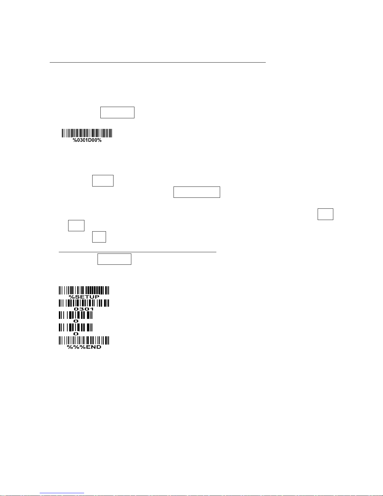
4-2 Example: configure scanner
Note: The factory default settings are indicated with asterisks (*) in this manual.
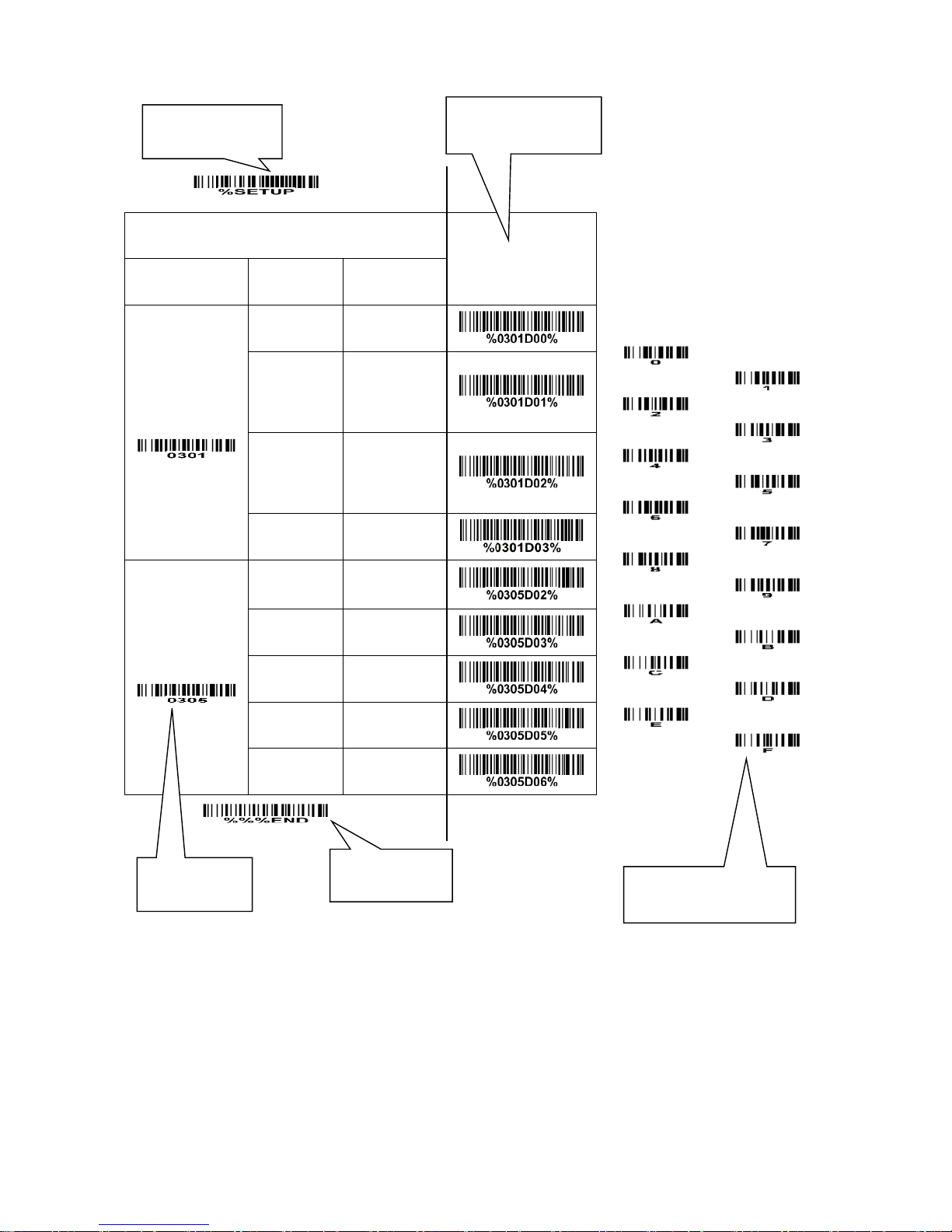
The scanner offers 3 methods to configure scanner: single-scan setting、multiple-scan setting and
command setting.
1、Single-scan setting
Scan the appropriate Single-scan setting barcode according to the user’s demand.
Example: Set Flow control to be none.
Steps: Scan the following barcode.
2、Multiple-scan setting
The steps of configuration are:
a) Scan the SETUP barcode on the parameter setting part.
b) Enter the option mode by scanning the Parameter name barcode.
c) To the right of the option barcode, the necessary alphanumeric inputs are listed. Scan these
alphanumeric entries (see
“12 Configuration alphanumeric value barcode”)
individually as Para.
Value.
d) Scan the END barcode, listed on the bottom of each parameter setting part.
Notes that only one parameter can be setup at each time.
Example: Set Flow control to be none.
Steps: Scan the following barcodes in order.
3、Command setting
Please refer to
“5-13 PARAM_SEND”
.
Page 20
14
SETUP
Multiple-scan setting
Single-scan setting
Option barcode
Option
Alpha. value
Flow control
None
00
RTS/CTS
(Host idle:
Low RTS)
01
RTS/CTS
(Host idle:
High CTS)
02
ACK/NAK
03*
Baud rate
1200
02
2400
03
4800
04
9600
05*
19200
06
END
Single-scan setting
Alphanumeric entries
Option barcode
END barcode
SETUP barcode
Page 21

15
4-3 RS232 interface
Flow control:
None- The communication only uses TXD and RXD signals without any hardware or software
handshaking protocol.
RTS/CTS- If the scanner requests to send the barcode data to host computer, it will issue the RTS
signal first, wait for the CTS signal from the host computer, and then perform the normal data
communication. If there is no replied CTS signal from the host computer after the Response delay
timeout, the scanner will issue an error indication. By setting (Host idle: Low RTS or Host idle: High
RTS), the scanner can be set to match the Serial Host RTS line.
ACK/NAK- If Decode data packet format is set to Packeted, after barcode data transmitted, the
scanner expects either an ACK (acknowledge) or NAK (not acknowledge) response from the host.
When a NAK is received, the scanner transmits the same data again and waits for either an ACK or
NAK. After three unsuccessful attempts to send data when NAK are received, the scanner issues an
error indication and discards the data.
When the scanner finishes receiving the command from host, it will send ACK/NAK to host. See
“5-3
CMD_ACK”
and
“5-4 CMD_NAK ”
for more information.
Note: If Decode data packet format is set to Raw, the scanner will not wait for ACK/NAK after
transmitting decoded data completely.
Response delay: This delay is the time that the scanner waits for a handshaking acknowledgment (NAK
or ACK) from the host.
Host-character delay: This delay is the time that the scanner waits for the host to send the next character
in serial communication.
Decode data packet format:
Raw- Scanner sends raw decoded data directly.
Packeted- The decoded data is sent in data packet (see
“5-5 DECODE_DATA”)
.
Page 22
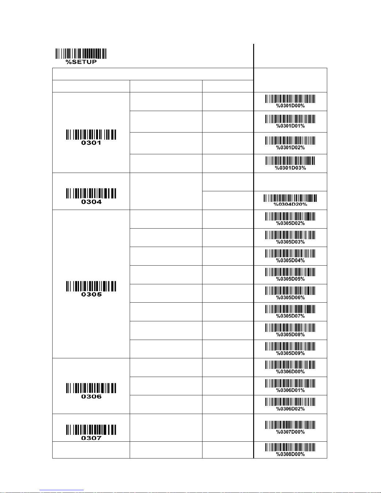
16
SETUP
Multiple-scan setting
Single-scan setting
Option barcode
Option
Alpha. value
Flow control
None
00
RTS/CTS
(Host idle: Low RTS)
01
RTS/CTS
(Host idle: High RTS)
02
ACK/NAK
03*
Response delay
01-99 (100 ms)
01-99
20*
Baud rate
1200
02
2400
03
4800
04
9600
05*
19200
06
38400
07
57600
08
115200
09
Parity
None
00*
Odd
01
Even
02
Data bit
8 bits
00*
Stop bit
1 bit
00*
Page 23
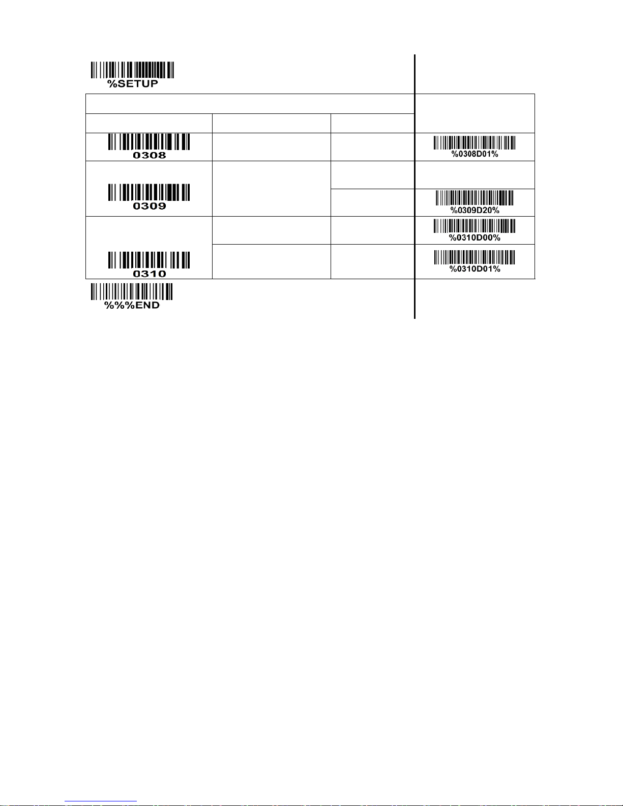
17
SETUP
Multiple-scan setting
Single-scan setting
Option barcode
Option
Alpha. value
2 bits
01
Host-character delay
01-99 (10ms)
01-99
20*
Decode data
packet format
Raw
00*
Packeted
01
END
Page 24

18
4-4 USB interface
USB device type:
HID keyboard– By setting, the scanner is used as a USB HID keyboard emulation device.
USB virtual COM– By setting, the scanner emulates a USB virtual COM device. If a Microsoft
Windows PC is connected to the scanner, a driver is required to install on the connected PC. The
driver will use the next available COM Port number. The driver and the installation guide can be found
in the associated CD and on the manufacturer’s website. A Windows-based software COM_Text is
recommended to display the barcode data in text format. COM_Text emulates some kind of serial-key
typing.
While emulating as a USB virtual COM, the scanner will send the data in data packet format if the
Decode data packet format is Packeted (see
“4-3 RS232 Interface”)
. The scanner also follows the
Flow control (see
“4-3 RS232 Interface”)
flow control, if it is set ACK/NAK.
Note: After changing USB Device Types, the scanner will restart automatically.
Keyboard layout: The scanner supports different national keyboard layouts.
Inter-character delay: This delay is inserted after each data character transmitted.
Numeric key:
Alphabetic key- The scanner will output code result as alphabetic key.
Numeric key- The scanner will output code result as pressing numeric keypad ( ‘0’, ‘1’, ‘2’, ‘3’, ‘4’, ‘5’,
‘6’, ‘7’, ‘8’, ‘9’, ‘.’, ‘+’, ‘-‘, ‘/’, ‘*’ only).
Alt+ keypad- The scanner will output code result as pressing Alt+ numeric key (on keypad). Note that
the Num Lock control key must be ON. This setting can be specially adapted for use with different
national keyboard layout.
Page 25
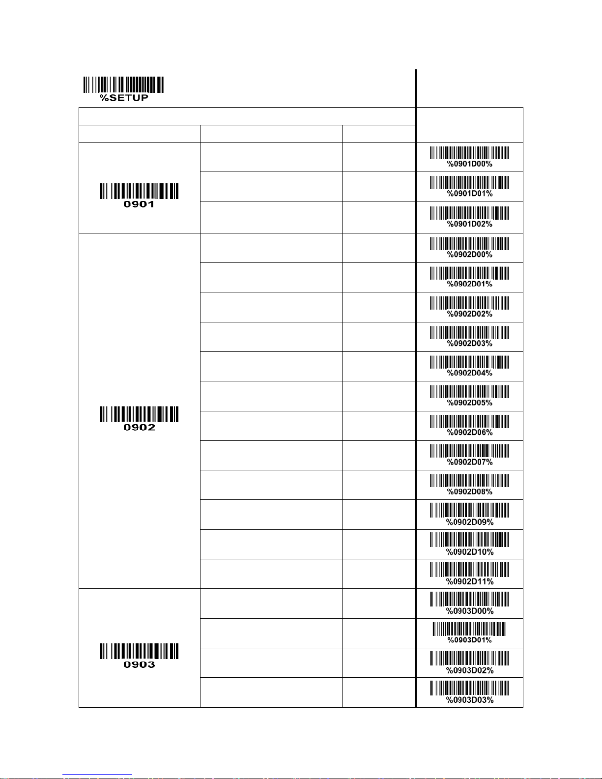
19
SETUP
Multiple-scan setting
Single-scan setting
Option barcode
Option
Alpha. value
USB device type
HID keyboard
00*
HID keyboard for Apple Mac
01
USB virtual COM
02
Keyboard layout
USA
00*
Turkish F
01
Turkish Q
02
French
03
Italian
04
Spanish
05
Slovak
06
Denmark
07
Japanese
08
German
09
Belgian
10
Russian
11
Inter-character delay
0 ms
00
5 ms
01*
10 ms
02
20 ms
03
Page 26
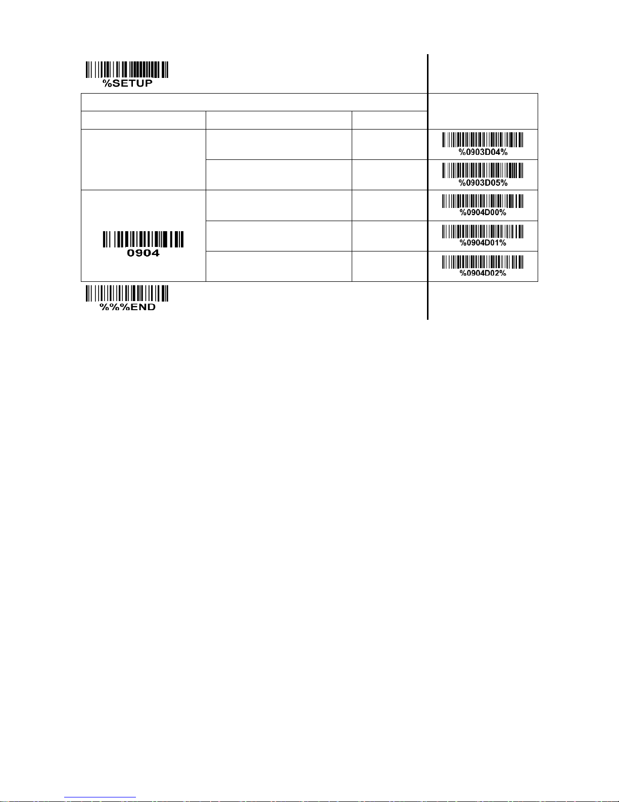
20
SETUP Multiple-scan setting
Single-scan setting
Option barcode
Option
Alpha. value
40 ms
04
60 ms
05
Numeric key
Alphabetic key
00*
Numeric keypad
01
Alt+ keypad
02
END
Page 27

21
4-5 Scan mode & some global settings
Scan mode:
Single scan- A scanning attempt is active once if trigger button is pressed or the command
STAR_DECODE is received. A scanning attempt stops when there is a successful reading or the
command STOP_DECODE is received or no barcode is decoded after the Stand-by duration elapses.
Continuous scan- The scanner always keeps scanning, and it does not matter when the trigger button
is pressed or Stand-by duration is elapsed or the command STOP_DECODE is received.
Auto-detection- The scanner will start scanning if any nearby object has been detected. The scanner
stops scanning when there is a successful reading or the command STOP_DECODE is received or no
barcode is decoded after the Stand-by duration elapsed. The Auto-detection function works again
only when the object leaves the scanner. The SCAN button is still valid when Auto-detection enabled.
Output-buffering Scan- The SCAN button acts as a toggle switch. Press the SCAN button to activate
or stop scanning. When scanning, it does not matter when Stand-by duration is elapsed or the
command STOP_DECODE is received. And the scanner will store the barcode data into a buffer
(buffer size: 1K byte). Until the SCAN button is pressed again to stop scanning, the scanner will send
all the barcode data in the buffer to host. When the unused space in the buffer is not enough to store
the current barcode data, the scanner will beep to warn and discard the current barcode data.
Note: Restoring the default settings by the host command or scanning the barcode that will not affect
the scan mode settings.
Standby duration: The duration time for a single scanning attempt.
Same barcode delay time: If a barcode has been scanned and output once successfully, the laser beam
must be off or moved away from the barcode beyond delay time to active next scanning the same
barcode. When this feature is set to be “0xFF”, then the delay time is indefinite.
Multiple confirm: If this parameter is set to be larger than zero, the scanner will require several
successful reads of same-decoded-data to confirm a valid reading. The number of successful reads can
be different according to different types of barcode. As the number of Multiple confirm gets larger, the
scanner’s aggressiveness decreases. The number of successful reads required for different types of
barcode is listed below, which is related to the parameter of Multiple confirm.
Page 28
22
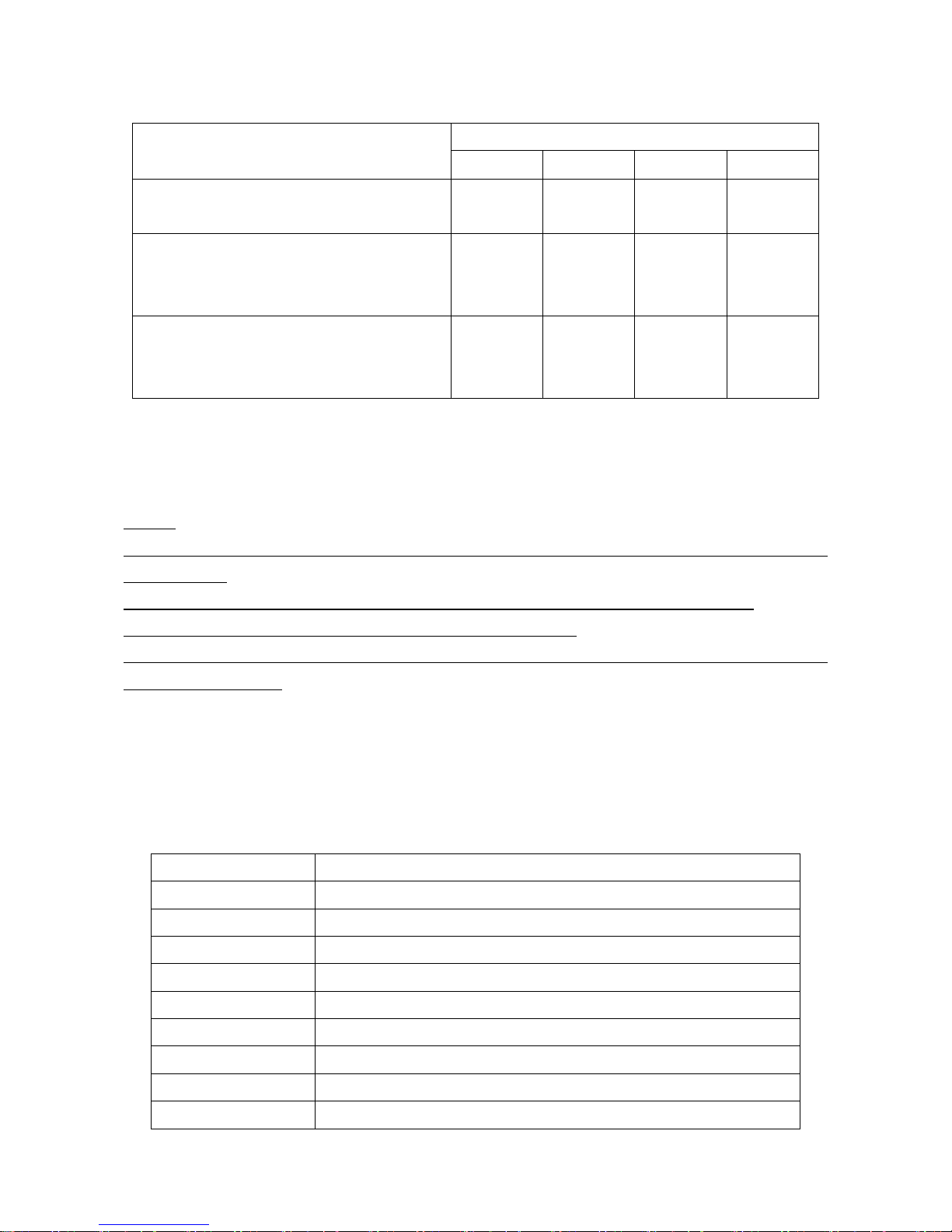
Table 6-1 The number of successful reads.
Barcode type
Multiple confirm (m)
m=0
m=1
m=2
m>=3
EAN-13, EAN-8, UPC-A, Code93, China
Post, UK Plessey
2 3 4
m+1
UPC-E, Codabar, Interleaved 2/5, Code39,
Industry2/5, Matrix 2/5, Code11, MSI
Plessey, UPC-E1
3 4 4
m+1
UCC/EAN128, Code128, GS1 DataBar,
GS1 DataBar Limited, GS1 DataBar
Expand, ISBT 128
1 2 3
m+1
Global Max./Min. code length: These two lengths are defined as the valid range of decoded barcode
data length. Make sure that the minimum length setting is no greater than the maximum length setting,
otherwise the labels of the symbol will not be readable. In particular, the same value can be set for both
minimum and maximum reading length to force the fixed length barcode decoded.
Notes:
1. Only set the Max./Min. code length for the specific code type to be zero, can Global Max./Min. code
length be valid.
2. Please refer to the settings of max./min. length for each specific code type in later sections
3. The number of check digits is included in max./min. code length.
4. These two settings have no effect on the symbols with fixed-length, e.g. UPC-A, UPC-E, EAN-13,
EAN-8 and China Post.
Global G1-G4 string selection: The scanner offer one or two string group for all symbols. By setting one
or two digits to indicate which string group you want to apply. You may refer to the chapters of
“4-28
G1-G4 & FN1 substitution string setting”
and
“4-29 G1-G4 string position & Code ID position”
.
Example: Group 1 → set 01 or 10. Group 2 and 4 → set 24 or 42.
All valid settings include 00, 01, 02, 03, 04, 10, 11, 12, 13, 14, 20, 21, 22, 23, 24, 30, 31, 32, 33, 34, 40,
41, 42, 43, and 44.
Setting value
Description
00
None
01、10、11
Only Group 1
02、20、22
Only Group 2
03、30、33
Only Group 3
04、40、44
Only Group 4
12、21
Group 1 first, then Group 2
13、31
Group 1 first, then Group 3
14、41
Group 1 first, then Group 4
23、32
Group 2 first, then Group 3
Page 29

23
Setting value
Description
24、42
Group 2 first, then Group 4
34、43
Group 3 first, then Group 4
Element amendment: If it is enabled, the scanner can read the barcode comprised with bars and spaces
in different scale.
Character output restraint:
Disable- the scanner will output all the barcode data .
Printable character only- If this option is selected, the scanner will output the printable characters only,
i.e. in ASCII from 20H to 7EH.
Alphanumeric character only- If this option is selected, the scanner will output the alphanumeric
characters only, i.e. “A”-“Z”, “a”-“z”, “0”-“9”.
Decoder optimization: If it is enabled, the scanner will optimize the decoder with error correction. This
function is not effective for all types of barcodes.
Scan angle: If narrow angle (40°) is selected, the decode rate is 1 time/scan; if wide angle (55°) is
selected, the decode rate is 0.5 time/scan.
Auto-sleep delay: After responding to the host’s requirement, the scanner will automatically enter deep
sleep state within Auto-sleep delay time. The scanner will be awakened while the SCAN button is
pressed or a command WAKEUP (0x00) is received again.
“No read” response: If it is enabled, while the scanner receives the STOP_DECODE command or fails to
decode a barcode within the Stand-by duration time, “NR” will be transmitted as decode data.
Deep sleep:
Disable- When Stand-by duration is elapsed, the scanner will enters normal sleep state. Any external
interrupt can wake up the scanner. It is not necessary to send a command WAKEUP (0x00) before
sending any other commands.
Enable- When Stand-by duration is elapsed, the scanner will enters sleep state deeply, and the
supply current will drop to be 0.9mA. And at this case, it is necessary to send a command WAKEUP
(0x00) and delay for 15ms, before sending any other commands.
Character encoding system: A character encoding system consists of a code that pairs each character
from a given repertoire. Common examples include Morse code, the Baudot code, the ASCII and
Unicode. If the data received does not display with the proper characters, it may be because the barcode
being scanned was created using a character encoding system that is different from the one the host
program is expecting. Try alternate options to find the proper one.
Page 30
24
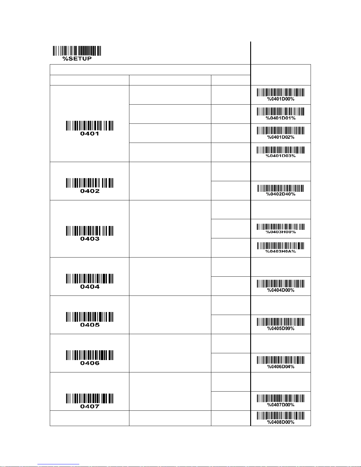
SETUP
Multiple-scan setting
Single-scan setting
Option barcode
Option
Alpha. value
Scanning mode
Note 1
Single Scan
00
Continuous Scan
01
Auto-detection
02
Output-buffering Scan
03
Standby duration
01-99 (100ms)
01-99
40*
Same barcode delay time
00-FF16(100ms)
(00:None)
00-FF16
00 0A*
Double confirm
00-09
(00:None)
00-09
00*
Global max. code length
04-99
04-99
99*
Global min. code length
01-99
01-99
04*
Global G1-G6 string
selection
00-44
(00:None)
00-44
00*
Element amendment
Disable
00
Page 31
25
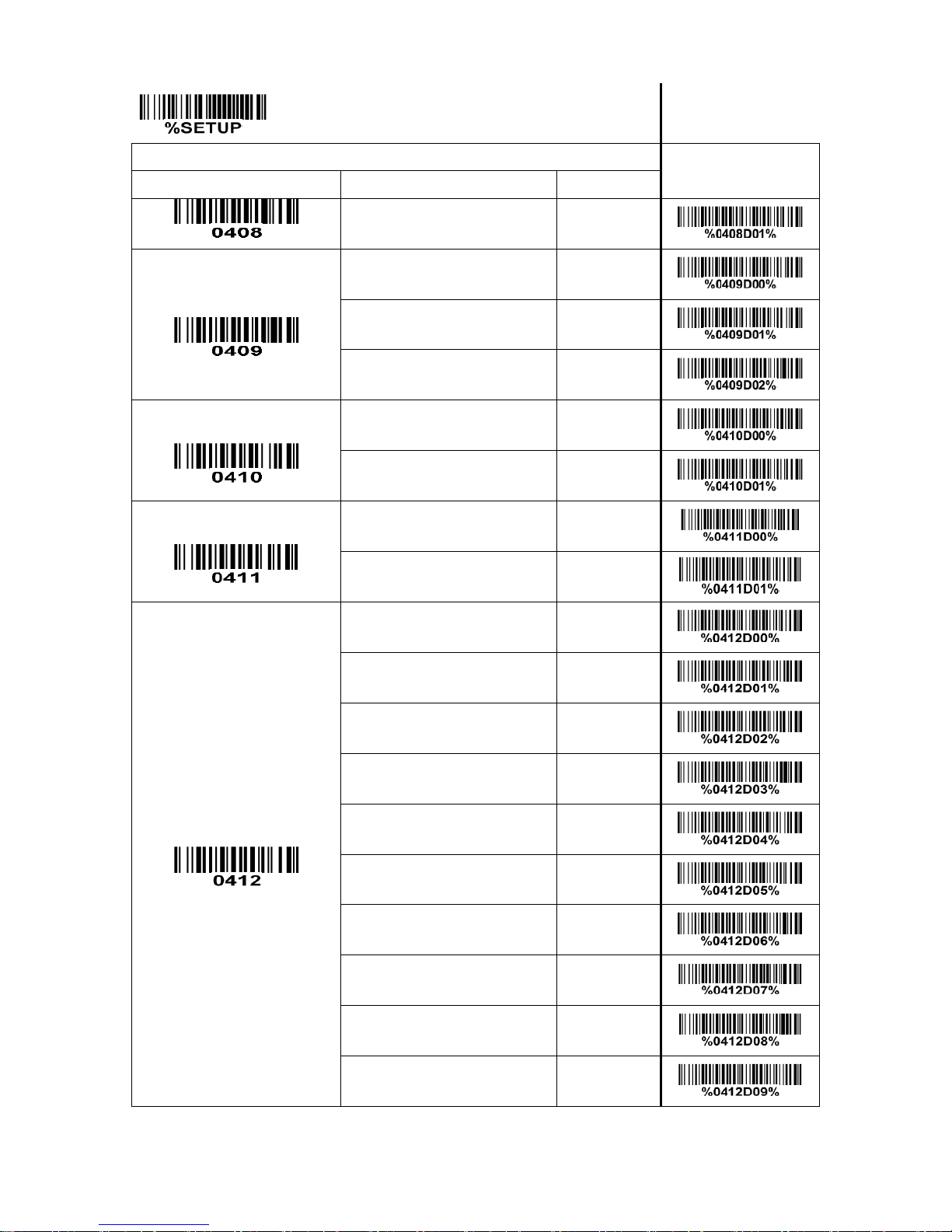
SETUP Multiple-scan setting
Single-scan setting
Option barcode
Option
Alpha. value
Enable
01*
Character output restraint
Disable
00*
Printable character only
01
Alphabetic & Numeric only
02
Decoder optimization
Disable
00
Enable
01*
Scan angle
Wide (56°)
00*
Narrow (40°)
01
Auto-sleep delay
Note 2
1 second
00
5 seconds
01
10 seconds
02
30 seconds
03*
1 minute
04
3 minutes
05
10 minutes
06
30 minutes
07
1 hour
08
3 hours
09
Page 32
26
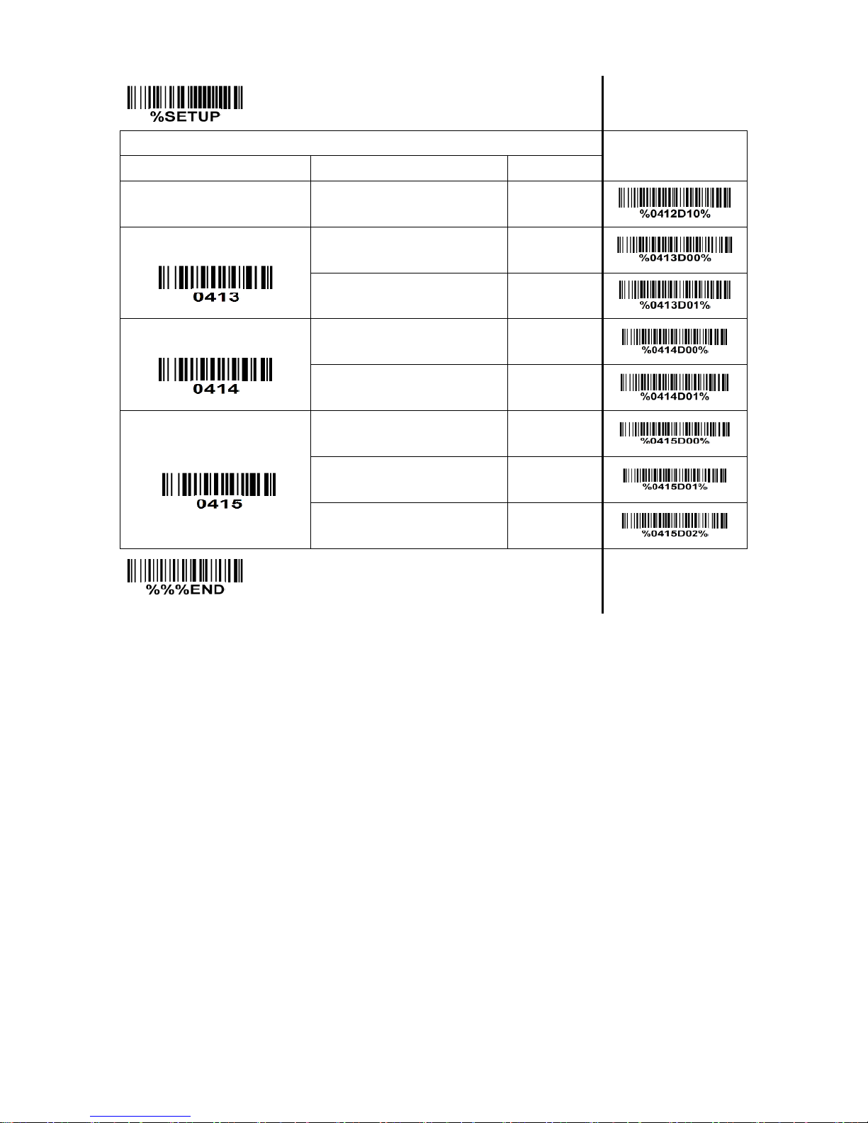
SETUP Multiple-scan setting
Single-scan setting
Option barcode
Option
Alpha. value
Never
10
“No read” response
Disable
00*
Enable
01
Deep sleep
Disable
00*
Enable
01
Character encoding system
ASCII
00*
UTF-8
01
Windows-1251
02
END
Note 1: This configure will not be changed when the scanner scans load default setting barcode or
receives PARAM_DEFAULTS command.
Note 2: The tolerance is ±20%.
Page 33
27
4-6 Indication
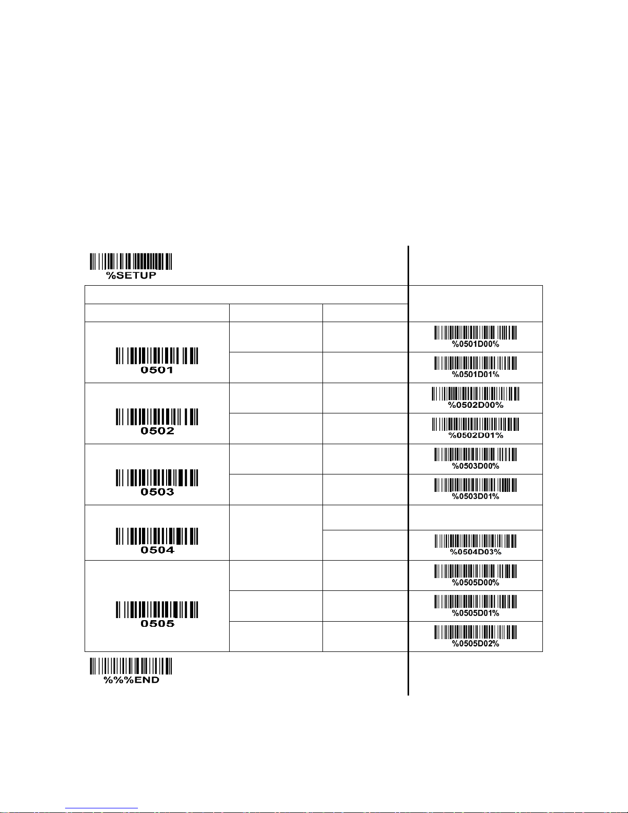
Power on alert: After power-on or restart, the scanner will generate alert signal (Beeper beeping and
LED flashing).
LED indication: When the scanner decodes successfully, the LED will glitter.
Beeper indication: After each successful reading, the scanner will beep to indicate a good barcode
reading, and its beep tone duration is adjustable.
Beep tone duration: This parameter can be adjusted for a good reading upon favorite usage.
Volume of beeper: This parameter can be adjusted for different level of the volume of the beeper.
SETUP Multiple-scan setting
Single-scan setting
Option barcode
Option
Alpha. value
Power on alert
Disable
00
Enable
01*
LED indication
Disable
00
Enable
01*
Beeper indication
Disable
00
Enable
01*
Beep tone duration
01-09 (25ms)
01-09
03*
Volume of beeper
Low
00
Middle
01
High
02*
END
Page 34
28
4-7 UPC-A
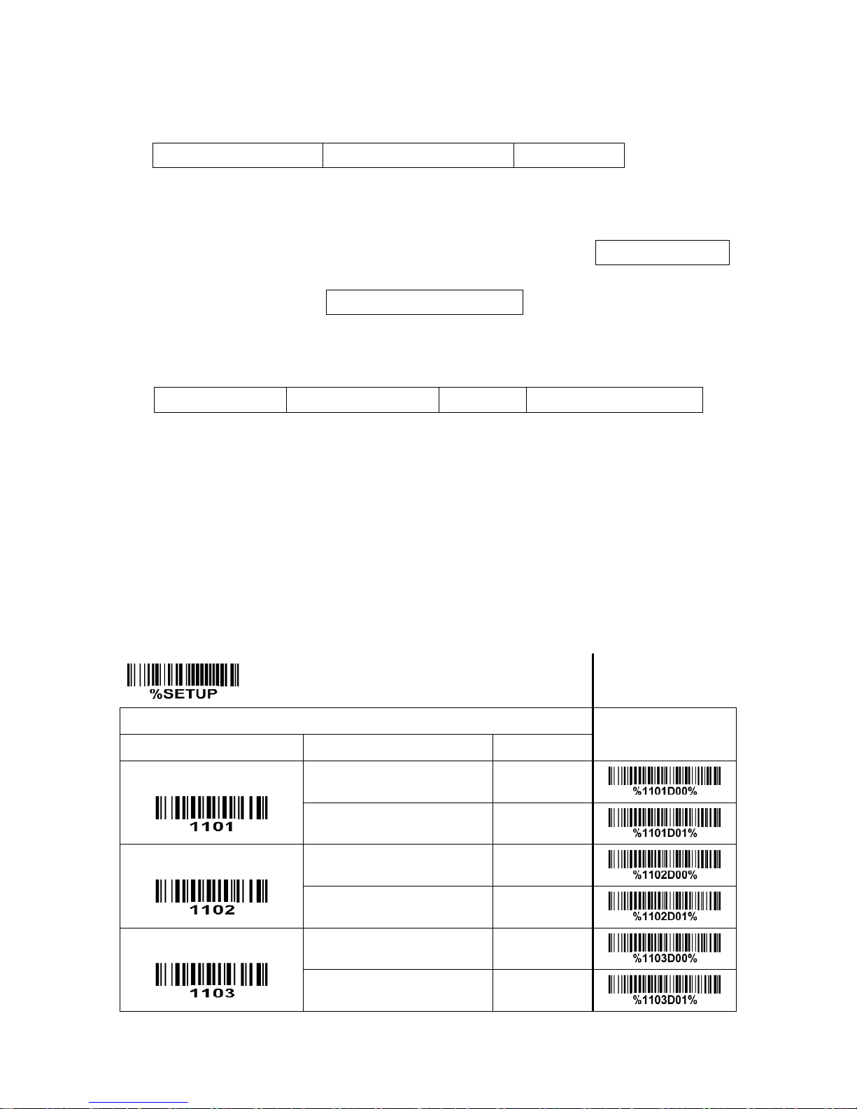
Read: Format
System character
Data digits (10 digits)
Check digit
Check digit verification: The check digit verification is optional.
Check digit trans.: By setting Enable, check digit will be transmitted.
Code ID setting: Code ID is a one-or-two-character string used to represent the symbol upon a
succeeding reading. If you want application to transmit Code ID, you must set Code ID transmission to
be enabled. Refer to the chapter of
“4-30 String transmission”
.
Insertion group selection: Refer to Global insertion group selection of the chapter of
“4-5 Scan mode&
some global settings”
.
Supplement digits: The Supplement digits barcode is the supplemental 2 or 5 characters.
Format
System character
Data digits (10 digits)
Check digit
Supplement digits 2 or 5
Truncation/Expansion:
Truncate leading zeros- The leading “0” digits of UPC-A data characters can be truncated when the
feature is enabled.
Expand to EAN-13- It extends to 13-digits with a “0” leading digit when the feature is enabled.
Truncate system character- The system character of UPC-A data can be truncated when the feature is
enabled.
Add country code- The country code (“0” for USA) can be added when the feature is enabled.
SETUP
Multiple-scan setting
Single-scan setting
Option barcode
Option
Alpha. value
Read
Disable
00
Enable
01*
Check digit verification
Disable
00
Enable
01*
Check digit trans.
Disable
00
Enable
01*
Page 35
29
SETUP
Multiple-scan setting
Single-scan setting
Option barcode
Option
Alpha. value
Code ID setting
00-FF
16
(ASCII)
00-FF
16
<A>*
Insert group selection
00-44
(00:None)
00-44
00*
Supplement digits
None
00*
2 digits
01
5 digits
02
2 or 5 digits
03
Truncation/Expansion
None
00*
Truncate leading zeros
01
Expand to EAN-13
02
Truncate system character
03
Add country code
04
Ink Spreading
Canceling
Note 1
Disable
00*
Enable
01
END
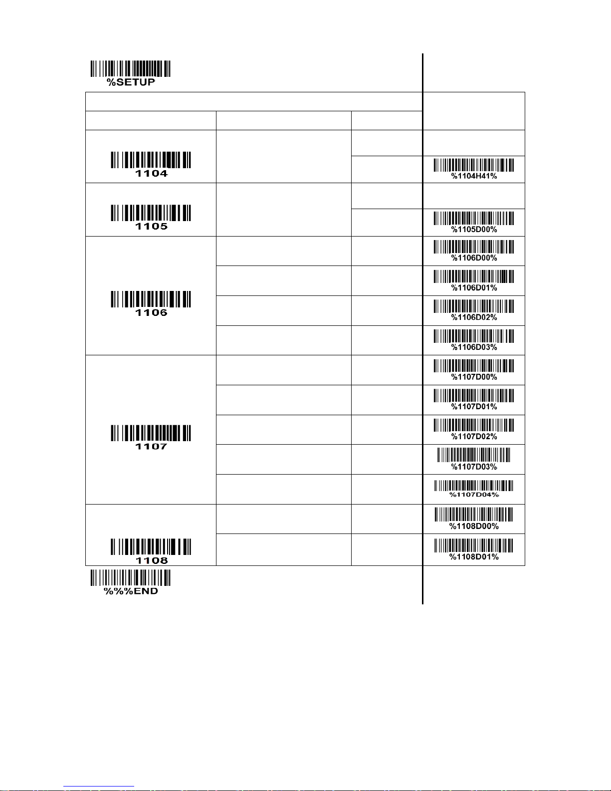
Note 1: If enabled, the scanner can more easily read the UPC-A barcode printed with ink spreading. But
it may cause the scanner to decode some well-printed UPC-A barcode wrongly. Please ask the advice
from the support engineer of the manufacturer before applying this function.
Page 36
30
4-8 UPC-E
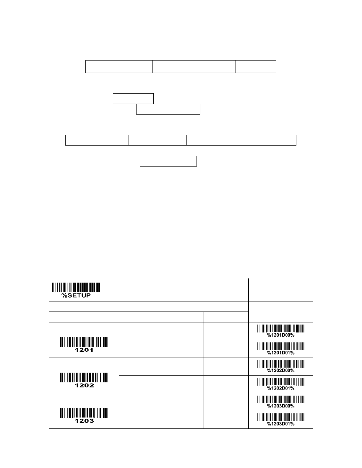
Read: Format
System character “0”
Data digits (6 digits)
Check digits
Check digit verification: The check digit verification is optional.
Check digit trans.: By setting Enable, check digit will be transmitted.
Code ID setting: Refer to Code ID setting of
“4-7 UPC-A”
.
Insertion group selection: Refer to Insertion group selection of
“4-7 UPC-A”
.
Supplement digits:
Format
System character “0”
Data digits (6 digits)
Check digit
Supplement digits 2 or 5
Truncation/Expansion:
Truncate leading zeros - Refer to Truncation/Expansion of
“4-7 UPC-A”
.
Expand to EAN-13 - It extends to 13-digits with “0” digits when the feature is set to be enabled.
Example: Barcode “01236547”, Output: “0012360000057”.
Expand to UPC-A - It extends to 12-digits when the feature is set to be enabled.
Example: Barcode “01236547”,
Output: “012360000057”.
Truncate system character - The system character “0” of UPC-E data can be truncated when this
feature is enabled.
Add country code - The country code (“0” for USA) can be added when the feature is enabled.
SETUP Multiple-scan setting
Single-scan setting
Option barcode
Option
Alpha. value
Read
Disable
00
Enable
01*
Check digit verification
Disable
00
Enable
01*
Check digit trans.
Disable
00
Enable
01*
Page 37
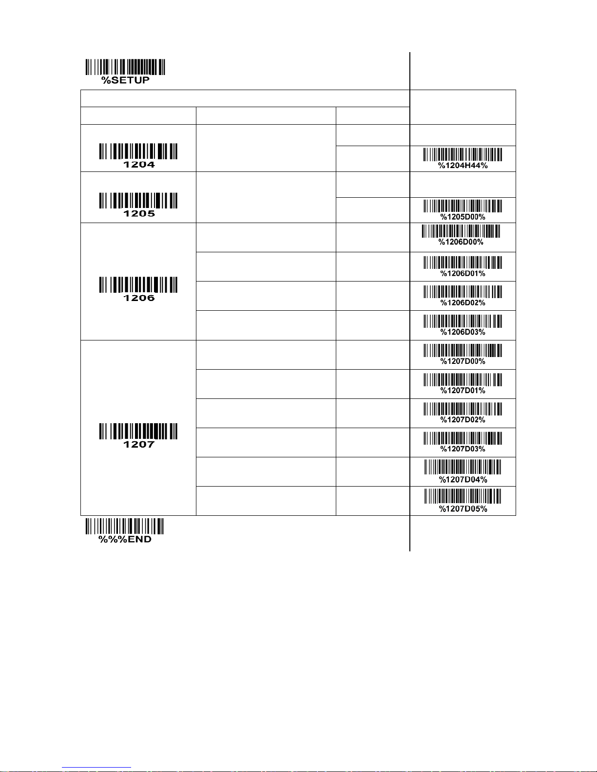
31
SETUP Multiple-scan setting
Single-scan setting
Option barcode
Option
Alpha. value
Code ID setting
00-FF16
(ASCII)
00-FF16
<D>*
Insert group selection
00-44
(00:None)
00-44
00*
Supplement digits
None
00*
*
2 digits
01
5 digits
02
2 or 5 digits
03
Truncation/Expansion
None
00*
Truncate leading zeros
01
Expand to EAN-13
02
Expand to UPC-A
03
Truncate system character
04
Add country code
05
END
Page 38

32
4-9 UPC-E1
Read: Format
System character “1”
Data digits (6 digits)
Check digits
Check digit verification: The check digit verification is optional.
Check digit trans.: By setting Enable, check digit will be transmitted.
Code ID setting: Refer to Code ID setting of
“4-7 UPC-A”
.
Insertion group selection: Refer to Insertion group selection of
“4-7 UPC-A”
.
Supplement digits:
Format
System character “1”
Data digits (6 digits)
Check digit
Supplement digits 2 or 5
Truncation/Expansion:
Expand to EAN-13 - It extends to 13-digits with “0” digits when the feature is set to be enabled.
Example: Barcode “11236597”, Output: “0112365000097”.
Expand to UPC-A - It extends to 12-digits when the feature is set to be enabled.
Example: Barcode “11236597”, Output: “112365000097”.
Truncate system character - The system character “1” of UPC-E1 data can be truncated when the
feature is enabled.
Add country code - The country code (“0” for USA) can be added when the feature is enabled.
Page 39
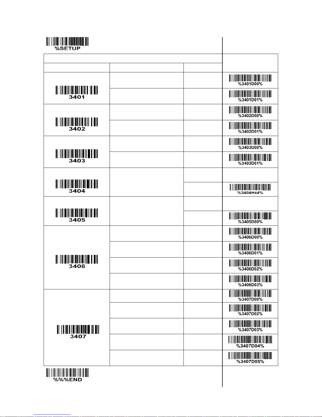
33
SETUP Multiple-scan setting
Single-scan setting
Option barcode
Option
Alpha. value
Read
Disable
00
Enable
01*
Check digit verification
Disable
00
Enable
01*
Check digit trans.
Disable
00
Enable
01*
Code ID setting
00-FF16
(ASCII)
00-FF16
<D>*
Insert group selection
00-44
(00:None)
00-44
00*
Supplement digits
None
00*
2 digits
01
5 digits
02
2 or 5 digits
03
Truncation/Expansion
None
00*
Expand to EAN-13
02
Expand to UPC-A
03
Truncate system character
04
Add country code
05
END
Page 40
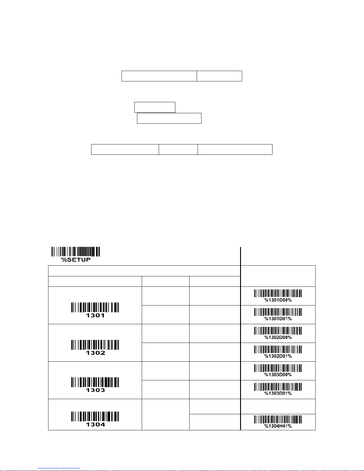
34
4-10 EAN-13 (ISBN/ISSN)
Read:
Format
Data digits (12 digits)
Check digit
Check digit verification: The check digit verification is optional.
Check digit transmission: By setting Enable, check digit will be transmitted.
EAN-13 code ID setting: Refer to Code ID setting of
“4-7 UPC-A”
.
Insertion group selection: Refer to Insertion group selection of
“4-7 UPC-A”
.
Supplement digits:
Format
Data digits (12 digits)
Check digit
Supplement digits 2 or 5
ISBN/ISSN: The ISBN (International Standard Book Number) and ISSN (International Standard Serial
Number) are two kinds of barcode for books and magazines. The ISBN is 10 digits with leading “978”
and the ISSN is 8 digits with leading “977” of the EAN-13 symbol.
Example:
Barcode “9780194315104”, Output: “019431510X”.
Barcode “9771005180004”, Output: “10051805”.
SETUP Multiple-scan setting
Single-scan setting
Option barcode
Option
Alpha. value
Read
Disable
00
Enable
01*
Check digit verification
Disable
00
Enable
01*
Check digit transmission
Disable
00
Enable
01*
EAN-13 code ID setting
00-FF16
(ASCII)
00-FF16
<A>*
Page 41
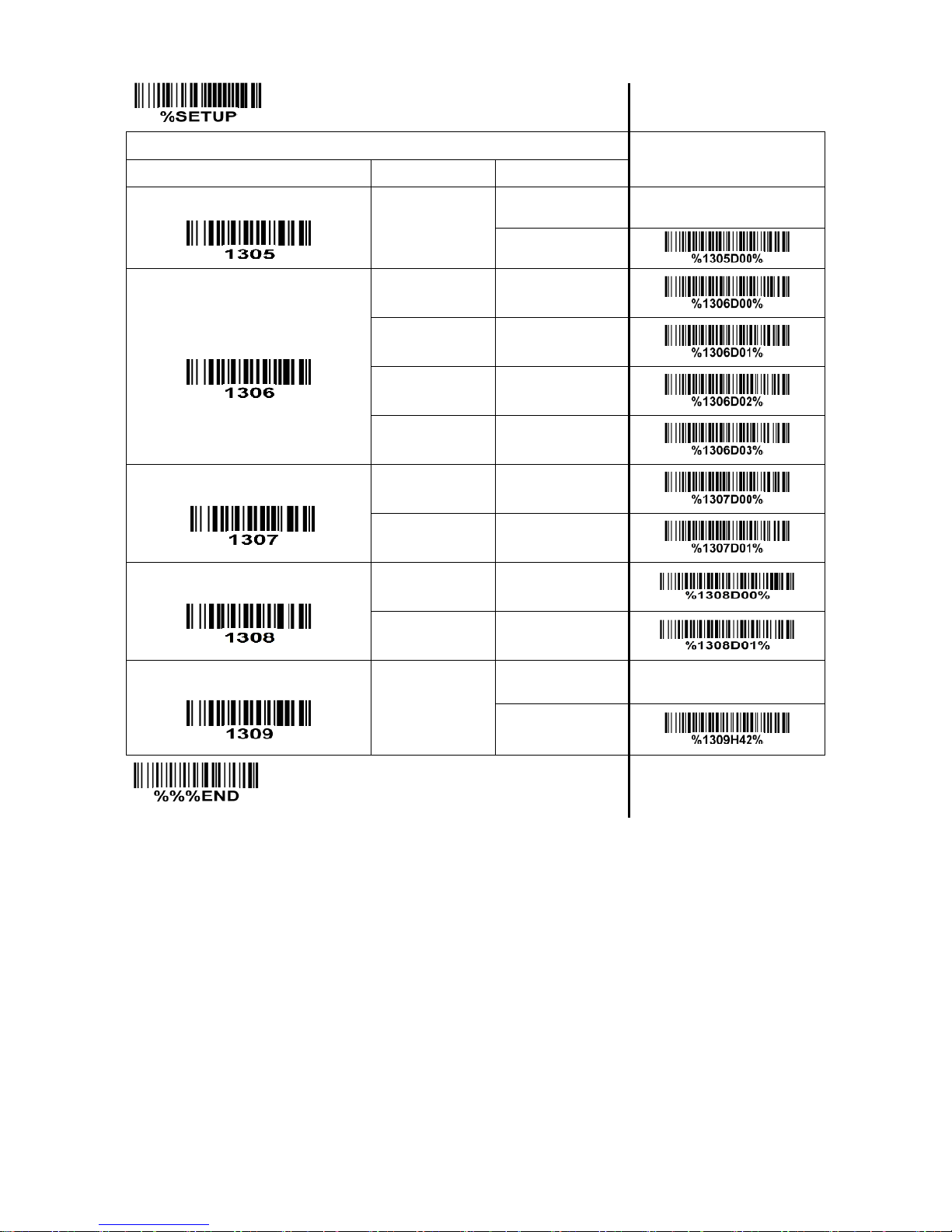
35
SETUP Multiple-scan setting
Single-scan setting
Option barcode
Option
Alpha. value
Insert group selection
00-44
(00:None)
00-44
00*
Supplement digits
None
00*
2 digits
01
5 digits
02
2 or 5 digits
03
ISBN/ISSN conversion
Disable
00*
Enable
01
Ink Spreading Canceling
Note 1
Disable
00*
Enable
01
ISBN/ISSN code ID setting
00-FF16
(ASCII)
00-FF16
<B>*
END
Note 1: If enabled, the scanner can more easily read the EAN-13 barcode printed with ink spreading. But
it may cause the scanner to decode some well-printed EAN-13 barcode wrongly. Please ask the advice
from the support engineer of the manufacturer before applying this function.
Page 42
36
4-11 EAN-8
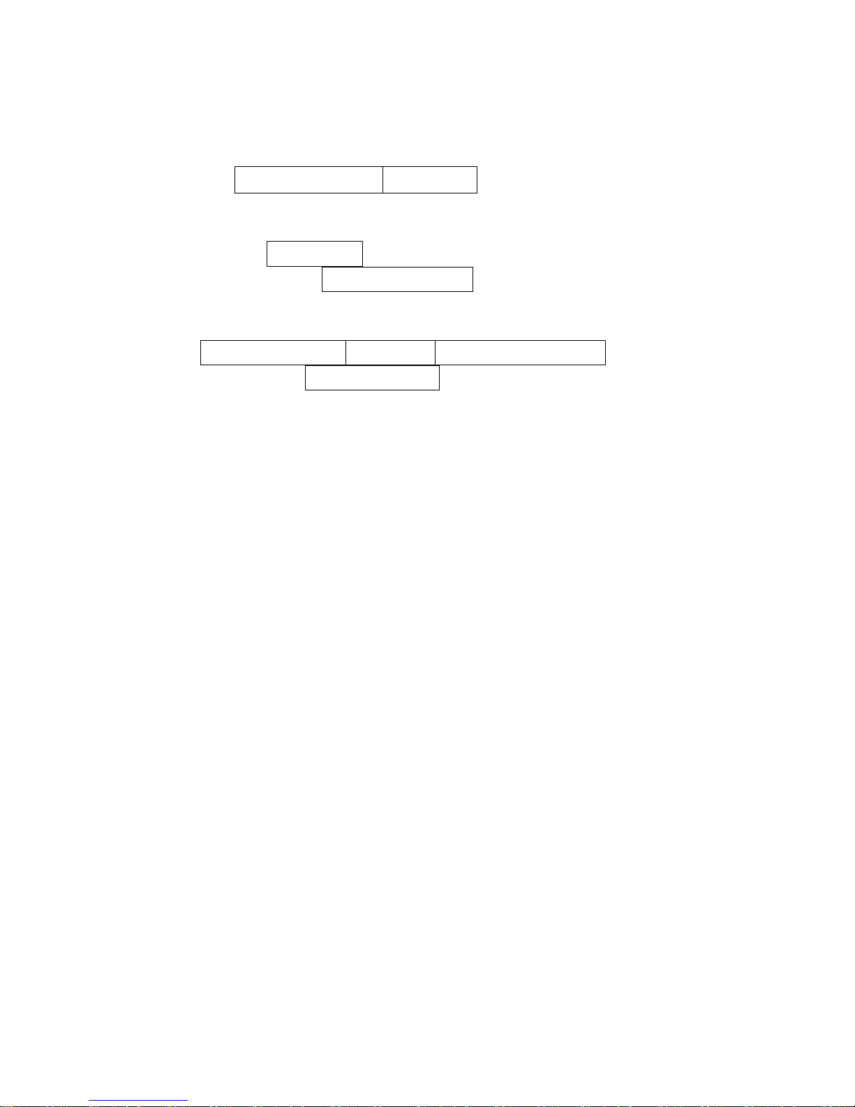
Read:
Format
Data digits (7 digits)
Check digit
Check digit verification: The check digit verification is optional.
Check digit trans.: By setting Enable, check digit will be transmitted.
Code ID setting: Refer to Code ID setting of
“4-7 UPC-A”
.
Insertion group selection: Refer to Insertion group selection of
“4-7 UPC-A”
.
Supplement digits:
Format
Data digits (7 digits)
Check digit
Supplement Digits 2 or 5
Truncation/Expansion: Refer to Truncation/Expansion of
“4-7 UPC-A”
.
Page 43
37
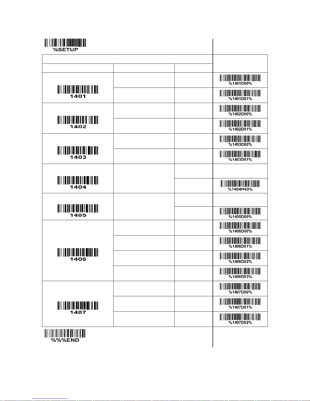
SETUP
Multiple-scan setting
Single-scan setting
Option barcode
Option
Alpha. value
Read
Disable
00
Enable
01*
Check digit verification
Disable
00
Enable
01*
Check digit trans.
Disable
00
Enable
01*
Code ID setting
00-FF16
(ASCII)
00-FF16
<C>*
Insert group selection
00-44
(00:None)
00-44
00*
Supplement digits
None
00*
2 digits
01
5 digits
02
2 or 5 digits
03
Truncation/Expansion
None
00*
Truncate leading zero
01
Expand to EAN-13
02
END
Page 44

38
4-12 Code 39 (Code 32, Trioptic Code 39)
Read:
Format
Start character(*)
Data digits (variable)
Check digit (optional)
End character(*)
Check digit verification: The check digit verification is optional.
Check digit transmission: By setting Enable, check digit will be transmitted.
Max./Min. code length: Each symbol has own max./min. code length. If both setting of max./min. code
length are “00”s, the setting of global max./min. code length is effective. The length is defined as to the
actual barcode data length to be sent. Label with length exceeds these limits will be rejected. Make sure
that the minimum length setting is no greater than the maximum length setting, otherwise all the labels of
the symbol will not be readable. In particular, you can see the same value for both minimum and
maximum reading length to force the fixed length barcode decoded. Refer to
“4-5 Scan mode & some
global settings”
.
Code ID setting: Refer to Code ID setting of
“4-7 UPC-A”
.
Insertion group selection: Refer to Insertion group selection of
“4-7 UPC-A”
.
Start/End transmission: The start character and end character of Code 39 are “*”s. You can transmit all
data digits including two “*”s.
“*” as data character: By setting Enable, “*” can be recognized as data character.
Convert Code 39 to Code 32: Code 32 is a variant of Code 39 used by the Italian pharmaceutical
industry. Note that Code 39 must be enabled in order for this parameter to function.
Format of Code 32
“A” (optional)
Data digits (8 digits)
Check digit
Code 32 Prefix “A” transmission: By setting Enable, the prefix character “A” can be added to all Code 32
barcodes.
Trioptic Code 39 read: Trioptic Code 39 is a variant of Code 39 used in the marking of magnetic tapes
and computer cartridges. Trioptic Code 39 symbols always contain six characters.
Format of Trioptic Code 39
Start character ($)
Data digits (6 digits)
End character ($)
Trioptic Code 39 Start/End transmission: The start character and end character of Trioptic Code 39 are
“$”s. You can transmit all data digits including two “$”s.
Page 45
39
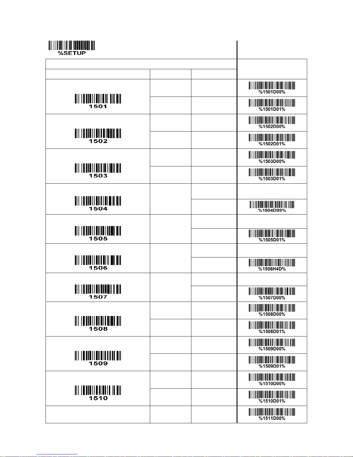
SETUP Multiple-scan setting
Single-scan setting
Option barcode
Option
Alpha. value
Read
Disable
00
Enable
01*
Check digit verification
Disable
00*
Enable
01
Check digit transmission
Disable
00*
Enable
01
Max. code length
00-99
00-99
99*
Min. code length
00-99
00-99
01*
Code ID setting
00-FF16
(ASCII)
00-FF16
<M>*
Insert group selection
00-44
(00:None)
00-44
00*
Format
Standard
00*
Full ASCII
01
Start/End transmission
Disable
00*
Enable
01
“*” as data character
Disable
00*
Enable
01
Convert Code 39 to Code 32
Disable
00*
Page 46
40
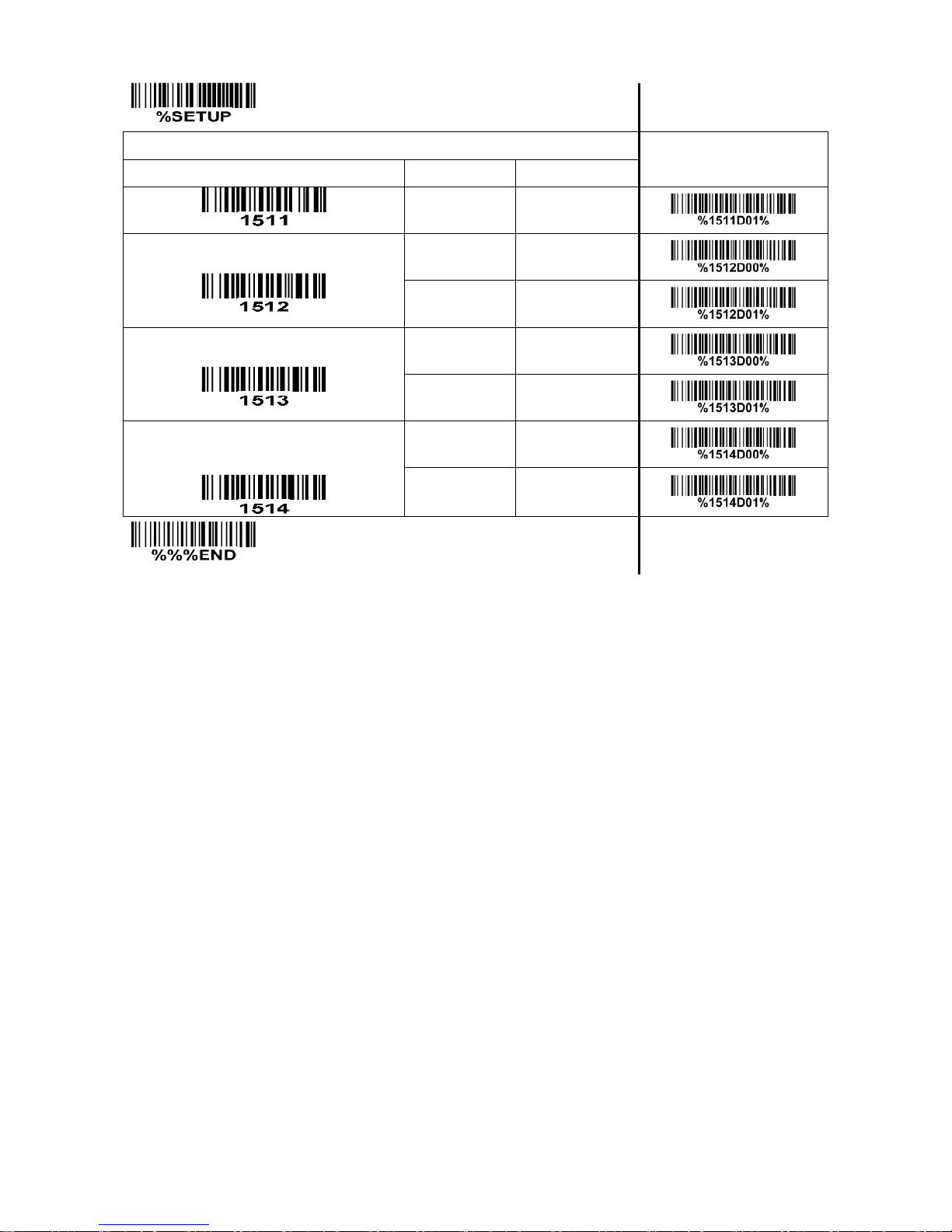
SETUP Multiple-scan setting
Single-scan setting
Option barcode
Option
Alpha. value
Enable
01
Code 32 Prefix “A” transmission
Disable
00*
Enable
01
Trioptic Code 39 read
Disable
00*
Enable
01
Trioptic Code 39 Start/End
transmission
Disable
00*
Enable
01
END
Note 1: If Trioptic Code 39 is set Enable, Code 39 is forced Enable.
Note 2: If Code 39 is set Disable, Trioptic Code 39 is forced Disable.
Page 47

41
4-13 Interleaved 2 of 5
Read:
Format
Data digits (variable)
Check digit (optional)
Check digit verification: The check digit verification is optional.
Check digit transmission: By setting Enable, check digit will be transmitted.
Max./Min. code length: Refer to Max./Min. code length of
“4-12 Code 39 (Code 32, Trioptic Code 39)”
.
Code ID setting: Refer to Code ID setting of
“4-7 UPC-A”
.
Insertion group selection: Refer to Insertion group selection of
“4-7 UPC-A”
.
Page 48
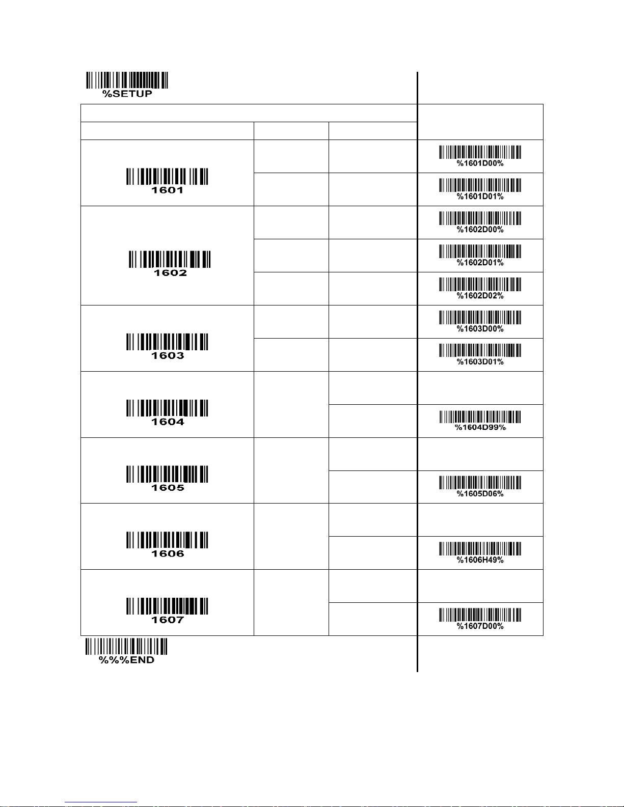
42
SETUP Multiple-scan setting
Single-scan setting
Option barcode
Option
Alpha. value
Read
Disable
00
Enable
01*
Check digit verification
Disable
00*
USS
01
OPCC
02
Check digit transmission
Disable
00*
Enable
01
Max. code length
00-99
00-99
99*
Min. code length
00-99
00-99
06*
Code ID setting
00-FF16
(ASCII)
00-FF16
<I>*
Insert group selection
00-44
(00:None)
00-44
00*
END
Page 49
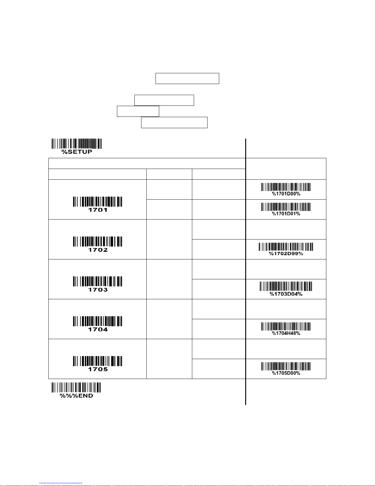
43
4-14 Industrial 2 of 5
Read:
Format
Data digits (variable)
Check digit transmission: By setting Enable, check digit will be transmitted.
Max./Min. code length: Refer to Max./Min. code length of
“4-12 Code 39 (Code 32, Trioptic Code 39)”
.
Code ID setting: Refer to Code ID setting of
“4-7 UPC-A”
.
Insertion group selection: Refer to Insertion group selection of
“4-7 UPC-A”
.
SETUP Multiple-scan setting
Single-scan setting
Option barcode
Option
Alpha. value
Read
Disable
00*
Enable
01
Max. code length
00-99
00-99
99*
Min. code length
00-99
00-99
04*
Code ID setting
00-FF16
(ASCII)
00-FF16
<H>*
Insert group selection
00-44
(00:None)
00-44
00*
END
Page 50

44
4-15 Matrix 2 of 5
Read:
Format
Data digits (variable)
Check digit (optional)
Check digit verification: The check digit verification is optional.
Check digit transmission: By setting Enable, check digit will be transmitted.
Max./Min. code length: Refer to Max./Min. code length of
“4-12 Code 39 (Code 32, Trioptic Code 39)”
.
Code ID setting: Refer to Code ID setting of
“4-7 UPC-A”
.
Insertion group selection: Refer to Insertion group selection of
“4-7 UPC-A”
.
Page 51
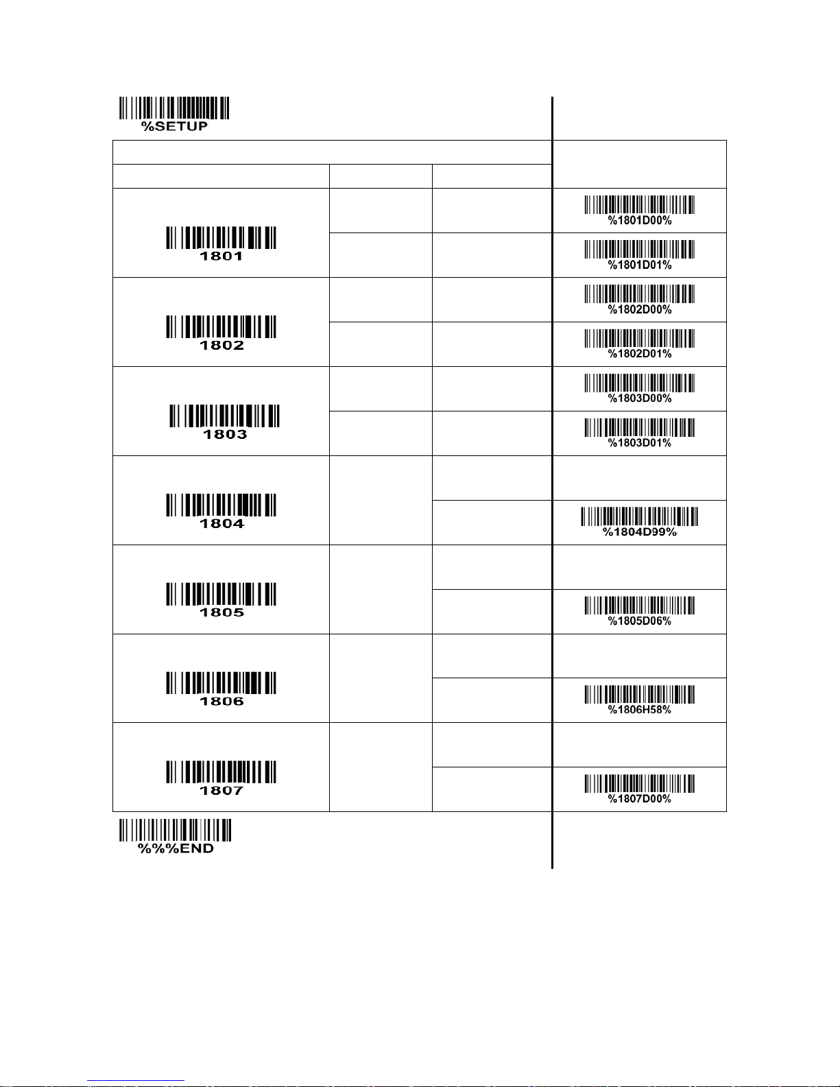
45
SETUP Multiple-scan setting
Single-scan setting
Option barcode
Option
Alpha. value
Read
Disable
00
Enable
01*
Check digit verification
Disable
00*
Enable
01
Check digit transmission
Disable
00*
Enable
01
Max. code length
00-99
00-99
99*
Min. code length
00-99
00-99
06*
Code ID setting
00-FF16
(ASCII)
00-FF16
<X>*
Insert group selection
00-44
(00:None)
00-44
00*
END
Page 52
46
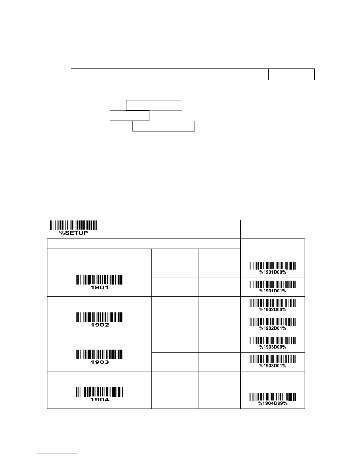
4-16 Codabar
Read:
Format
Start character
Data digits (variable)
Check digit (optional)
End character
Check digit verification: The check digit verification is optional.
Check digit transmission: By setting Enable, check digit will be transmitted.
Max./Min. code length: Refer to Max./Min. code length of
“4-12 Code 39 (Code 32, Trioptic Code 39)”
.
Code ID setting: Refer to Code ID setting of
“4-7 UPC-A”
.
Insertion group selection: Refer to Insertion group selection of
“4-7 UPC-A”
.
Start/End type: Codabar has four pairs of Start/End pattern; you may select one pair to match your
application.
Start/End transmission: By setting Enable, the start and end character of a Codabar barcode will be
transmitted.
Start/End character equality: By setting Enable, the start and end character of a Codabar barcode must
be the same.
SETUP Multiple-scan setting
Single-scan setting
Option barcode
Option
Alpha. value
Read
Disable
00
Enable
01*
Check digit verification
Disable
00*
Enable
01
Check digit transmission
Disable
00*
Enable
01
Max. code length
00-99
00-99
99*
Page 53
47
SETUP Multiple-scan setting
Single-scan setting
Option barcode
Option
Alpha. value
Min. code length
00-99
00-99
04*
Code ID setting
00-FF16
(ASCII)
00-FF16
<N>*
Insert group selection
00-44
(00:None)
00-44
00*
Start/End type
ABCD/ABCD
00*
abcd/abcd
01
ABCD/TN*E
02
abcd/tn*e
03
Start/End transmission
Disable
00*
Enable
01
Start/End character equality
Disable
00*
Enable
01
END
Page 54

48
4-17 Code 128
Read:
Format
Data digits (variable)
Check digit (optional)
Check digit verification: The check digit verification is optional.
Check digit transmission: By setting Enable, check digit will be transmitted.
Max./Min. code length: Refer to Max./Min. code length of
“4-12 Code 39 (Code 32, Trioptic Code 39)”
.
Code ID setting: Refer to Code ID setting of
“4-7 UPC-A”
.
Insertion group selection: Refer to Insertion group selection of
“4-7 UPC-A”
.
Truncate leading zeros: The leading “0” digits or all “0” digits of Code 128 barcode characters can be
truncated when the feature is enabled.
Page 55
49
SETUP Multiple-scan setting
Single-scan setting
Option barcode
Option
Alpha. value
Read
Disable
00
Enable
01*
Check digit verification
Disable
00
Enable
01*
Check digit transmission
Disable
00*
Reserved
01
Max. code length
00-99
00-99
99*
Min. code length
00-99
00-99
01*
Code ID setting
00-FF16
(ASCII)
00-FF16
<K>*
Insert group selection
00-44
(00:None)
00-44
00*
Truncate leading zeros
Disable
00*
All leading “0”s
01
Only the first “0”
02
END
Page 56

50
4-18 UCC/EAN 128
Read:
Format
Data digits (variable)
Check digit (optional)
Check digit verification: The check digit verification is optional.
Check digit transmission: By setting Enable, check digit will be transmitted.
Max. /Min. code length: Refer to Max. /Min. code length of
“4-12 Code 39 (Code 32, Trioptic Code 39)”
.
Code ID setting: Refer to Code ID setting of
“4-7 UPC-A
.”
Insertion group selection: Refer to Insertion group selection of
“4-7 UPC-A”
.
Truncate leading zeros: The leading “0” digits or all “0” digits of UCC/EAN 128 barcode characters can
be truncated when the feature is enabled.
Page 57
51
SETUP Multiple-scan setting
Single-scan setting
Option barcode
Option
Alpha. value
Read
Disable
00
Enable
01*
Check digit verification
Disable
00
Enable
01*
Check digit transmission
Disable
00*
Reserved
01
Max. code length
00-99
00-99
99*
Min. code length
00-99
00-99
01*
Code ID setting
00-FF16
(ASCII)
00-FF16
<K>*
Insert group selection
00-44
(00:None)
00-44
00*
Truncate leading zeros
Disable
00*
All leading “0”s
01
Only the first “0”
02
END
Page 58

52
4-19 ISBT 128
Read:
Format
Start character(“=” or “&”)
Data digits (variable)
Check digit (optional)
Check digit verification: The check digit verification is optional.
Check digit transmission: By setting Enable, check digit will be transmitted.
Max./Min. code length: Refer to Max./Min. code length of
“4-12 Code 39 (Code 32, Trioptic Code 39)”
.
Code ID setting: Refer to Code ID setting of
“4-7 UPC-A”
.
Insertion group selection: Refer to Insertion group selection of
“4-7 UPC-A”
.
Page 59
53
SETUP Multiple-scan setting
Single-scan setting
Option barcode
Option
Alpha. value
Read
Disable
00
Enable
01*
Check digit verification
Disable
00
Enable
01*
Check digit transmission
Disable
00*
Reserved
01
Max. code length
00-99
00-99
99*
Min. code length
00-99
00-99
01*
Code ID setting
00- FF16
(ASCII)
00-FF16
<K>*
Insert group selection
00-44
(00:None)
00-44
00*
END
Page 60

54
4-20 Code 93
Read:
Format
Data digits (variable)
2 check digits (optional)
Check digit verification: The check digit verification is optional.
Check digit transmission: By setting Enable, check digit will be transmitted.
Max./Min. code length: Refer to Max./Min. code length of
“4-12 Code 39 (Code 32, Trioptic Code 39)”
.
Code ID setting: Refer to Code ID setting of
“4-7 UPC-A”
.
Insertion group selection: Refer to Insertion group selection of
“4-7 UPC-A”
.
Page 61
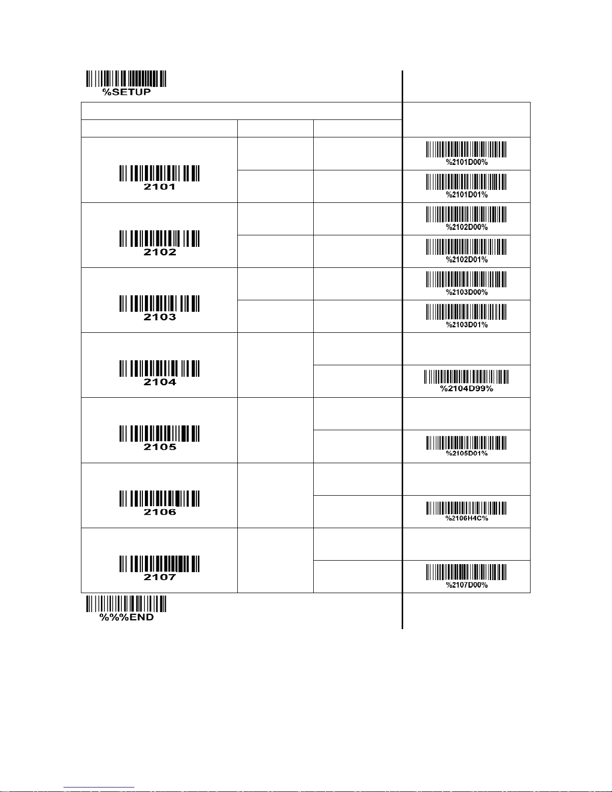
55
SETUP Multiple-scan setting
Single-scan setting
Option barcode
Option
Alpha. value
Read
Disable
00
Enable
01*
Check digit verification
Disable
00
Enable
01*
Check digit transmission
Disable
00*
Enable
01
Max. code length
00-99
00-99
99*
Min. code length
00-99
00-99
01*
Code ID setting
00-FF16
(ASCII)
00-FF16
<L>*
Insert group selection
00-44
(00:None)
00-44
00*
END
Page 62

56
4-21 Code 11
Read:
Format
Data digits (variable)
1 or 2 check digits (optional)
Check digit verification: The check digit verification is optional.
Check digit transmission: By setting Enable, 1 or 2 check digits will be transmitted upon the selected
check digit verification method.
Max./Min. code length: Refer to Max./Min. code length of
“4-12 Code 39 (Code 32, Trioptic Code 39)”
.
Code ID setting: Refer to Code ID setting of
“4-7 UPC-A”
.
Insertion group selection: Refer to Insertion group selection of
“4-7 UPC-A”
.
Page 63
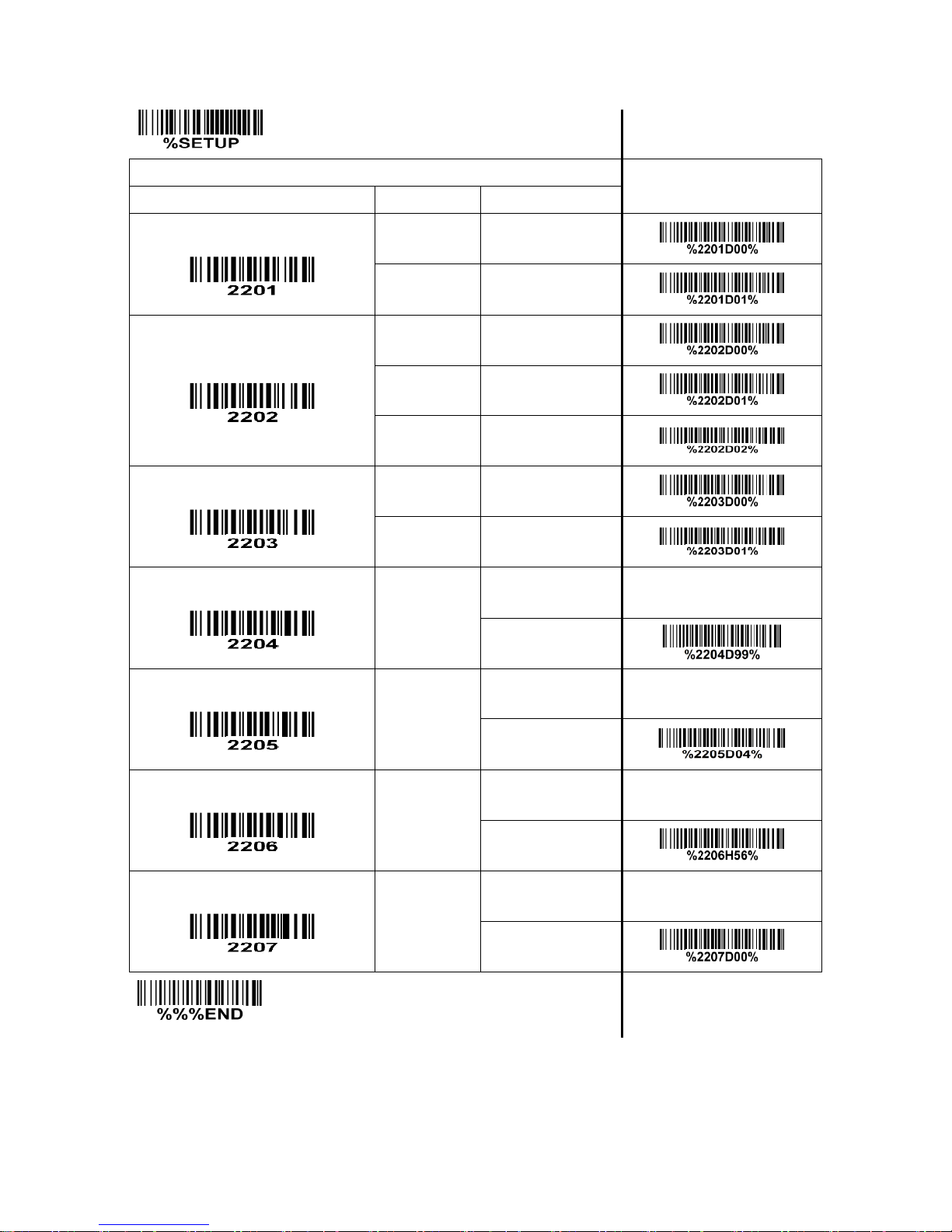
57
SETUP Multiple-scan setting
Single-scan setting
Option barcode
Option
Alpha. value
Read
Disable
00*
Enable
01
Check digit verification
Disable
00
One digit
01*
Two digit
02
Check digit transmission
Disable
00*
Enable
01
Max. code length
00-99
00-99
99*
Min. code length
00-99
00-99
04*
Code ID setting
00-FF16
(ASCII)
00-FF16
<V>*
Insert group selection
00-44
(00:None)
00-44
00*
END
Page 64

58
4-22 MSI/Plessey
Read:
Format
Data digits (variable)
1 or 2 check digits (optional)
Check digit verification: The MSI/Plessey has one or two optional check digits. There are three methods
to verify check digits, i.e. Mod10, Mod10/10 and Mod 10/11. 1 or 2 check digits will be calculated as the
sum module 10 or 11 of the data digits.
Check digit transmission: By setting Enable, 1 or 2 check digits will be transmitted upon the selected
check digit verification method.
Max./Min. code length: Refer to Max./Min. code length of
“4-12 Code 39 (Code 32, Trioptic Code 39)”
.
Code ID setting: Refer to Code ID setting of
“4-7 UPC-A”
.
Insertion group selection: Refer to Insertion group selection of
“4-7 UPC-A”
.
Page 65
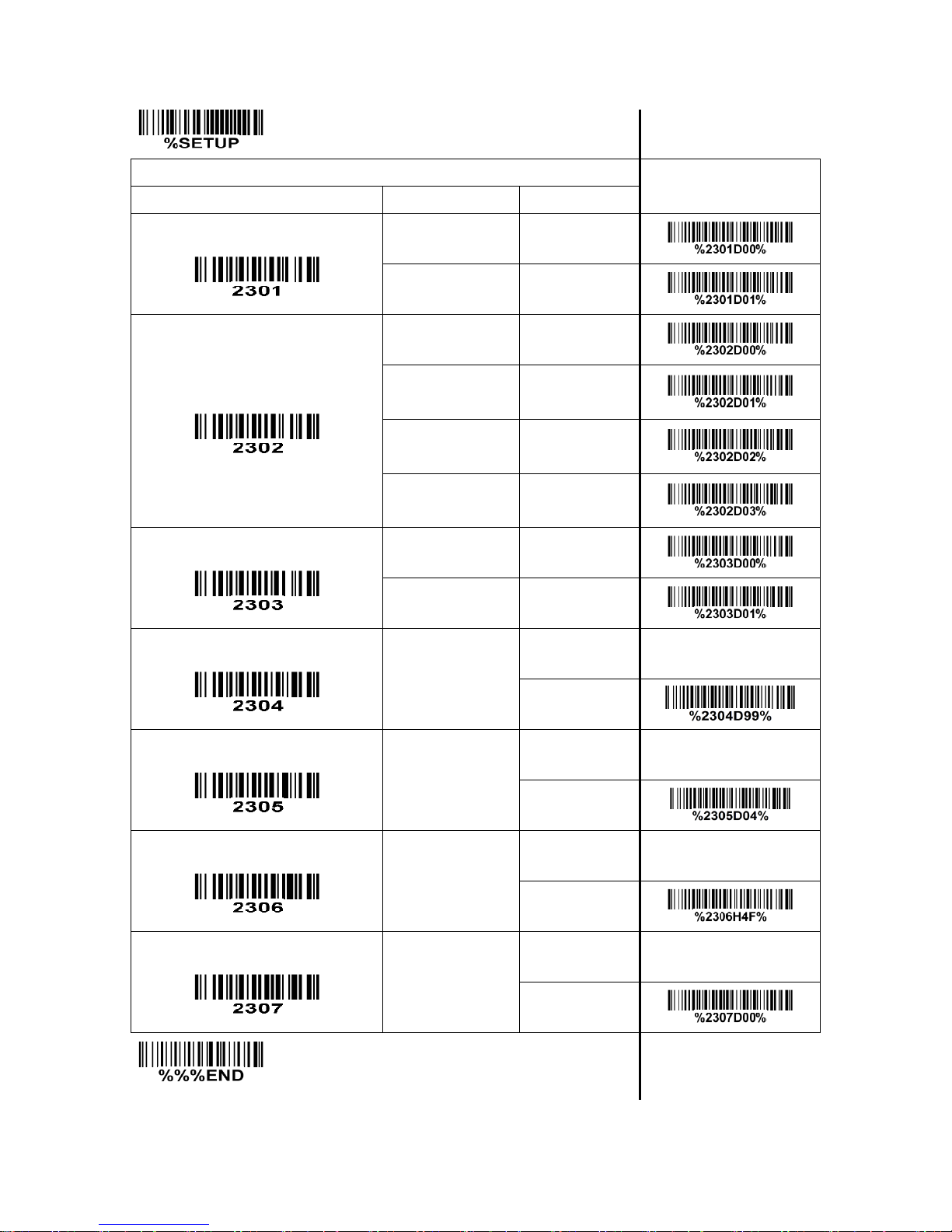
59
SETUP Multiple-scan setting
Single-scan setting
Option barcode
Option
Alpha. value
Read
Disable
00*
Enable
01
Check digit verification
Disable
00*
1 digit
(Mod 10)
01
2 digit
(Mod 10/10)
02
2 digit
(Mod 10/11)
03
Check digit transmission
Disable
00*
Enable
01
Max. code length
00-99
00-99
99*
Min. code length
00-99
00-99
04*
Code ID setting
00-FF16
(ASCII)
00-FF16
<O>*
Insert group selection
00-44
(00:None)
00-44
00*
END
Page 66

60
4-23 UK/Plessey
Read:
Format
Data digits (variable)
2 check digits (optional)
Check digit verification: The UK/Plessey has two optional check digits. The check digit 1 and check digit
2 will be calculated as the sum module 10 or 11 of the data digits.
Check digit transmission: By setting Enable, check digit will be transmitted.
Max./Min. code length: Refer to Max./Min. code length of
“4-12 Code 39 (Code 32, Trioptic Code 39)”
.
Code ID setting: Refer to Code ID setting of
“4-7 UPC-A”
.
Insertion group selection: Refer to Insertion group selection of
“4-7 UPC-A”
.
Page 67
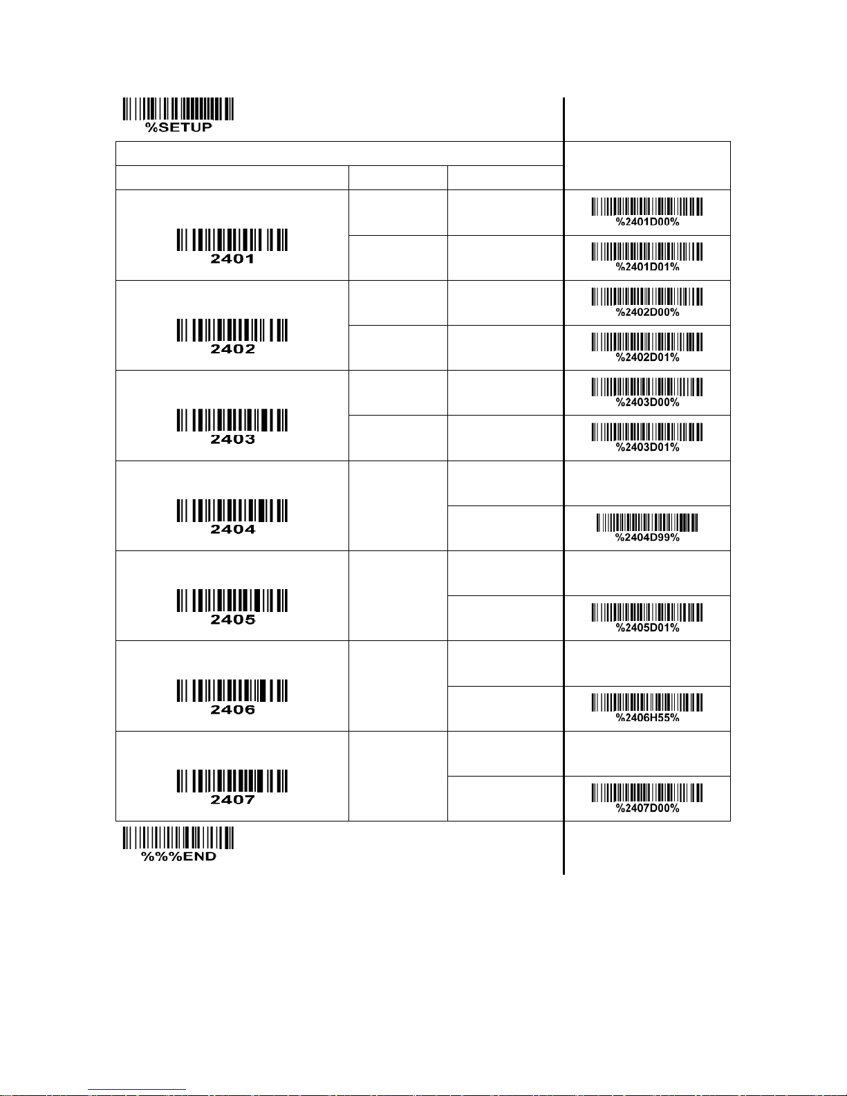
61
SETUP Multiple-scan setting
Single-scan setting
Option barcode
Option
Alpha. value
Read
Disable
00
Enable
01*
Check digit verification
Disable
00
Enable
01*
Check digit transmission
Disable
00*
Enable
01
Max. code length
00-99
00-99
99*
Min. code length
00-99
00-99
01*
Code ID setting
00-FF16
(ASCII)
00-FF16
<U>*
Insert group selection
00-44
(00:None)
00-44
00*
END
Page 68
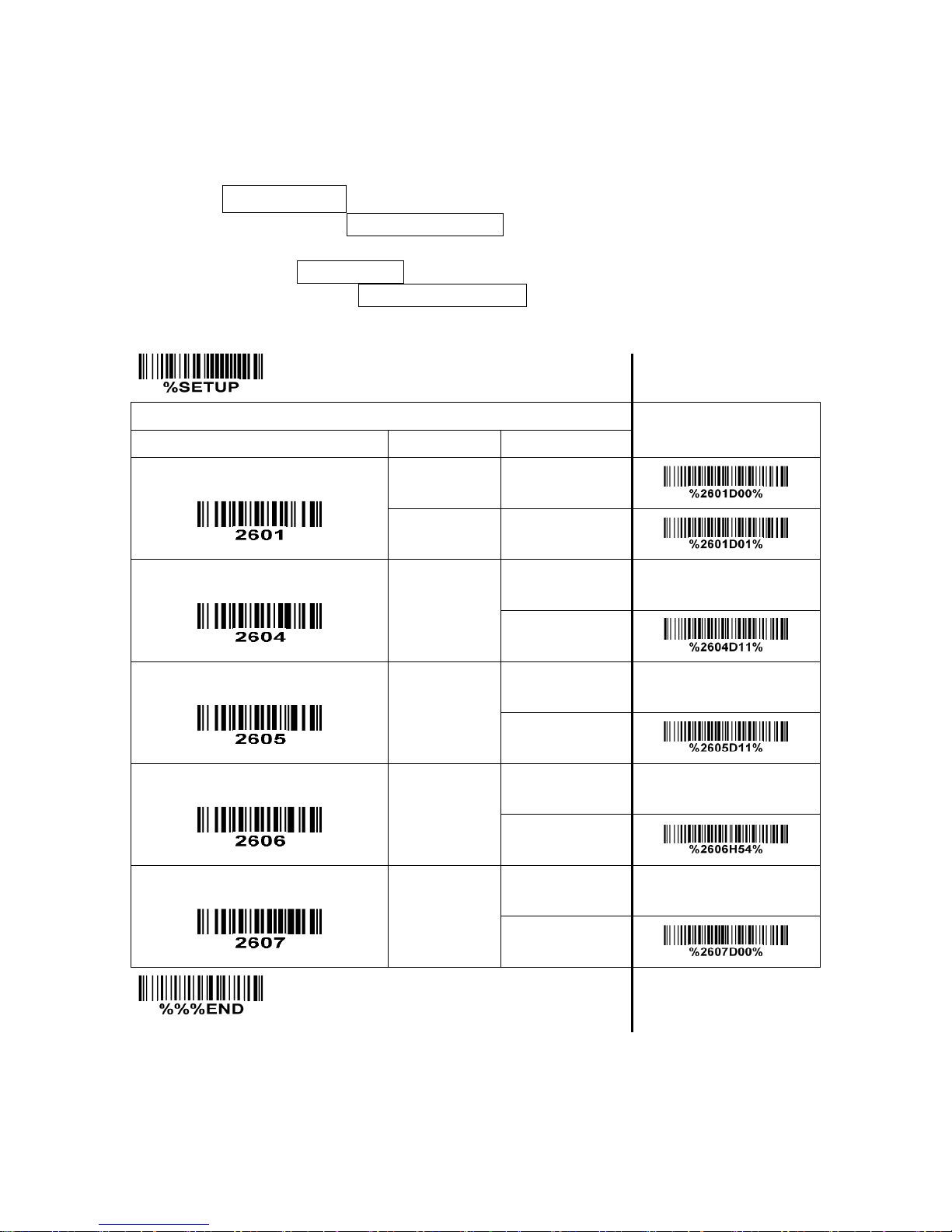
62
4-24 China Post
Read:
Format
11 Data digits
Max. /Min. code length: Refer to Max. /Min. code length of
“4-12 Code 39 (Code 32, Trioptic Code 39)”
.
The code length of China Post is 11.
Code ID setting: Refer to Code ID setting of
“4-7 UPC-A”
.
Insertion group selection: Refer to Insertion group selection of
“4-7 UPC-A”
.
SETUP
Multiple-scan setting
Single-scan setting
Option barcode
Option
Alpha. value
Read
Disable
00
Enable
01*
Max. code length
00-99
00-99
11*
Min. code length
00-99
00-99
11*
Code ID setting
00-FF16
(ASCII)
00-FF16
<T>*
Insert group selection
00-44
(00:None)
00-44
00*
END
Page 69
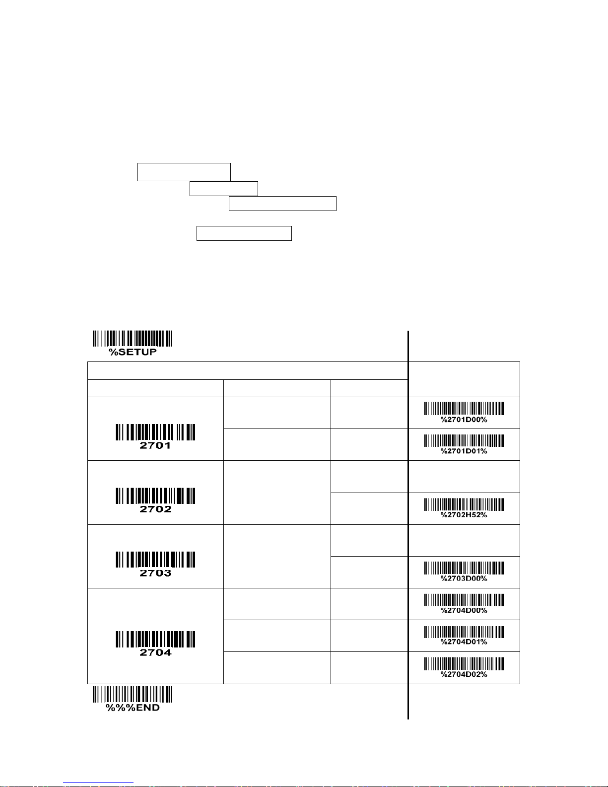
63
4-25 GS1 DataBar (GS1 DataBar Truncated)
GS1 DataBar Truncated is structured and encoded as the same as the standard GS1 DataBar format,
except its height is reduced to a 13 modules minimum; while GS1 DataBar should have a height greater
than or equal to 33 modules.
Read:
Format
16 Data digits
Code ID setting: Refer to Code ID setting of
“4-7 UPC-A”
.
Insertion group selection: Refer to Insertion group selection of
“4-7 UPC-A”
.
Conversion:
UCC/EAN 128- Refer to Code ID transmission of “
4-30 String transmission
”, ]Cm will be identified as
AIM ID.
UPC-A or EAN-13- Barcode beginning with a single zero as the first digit has the leading “010”
stripped and the barcode reported as EAN-13. Barcode beginning with two or more zeros but not six
zeros has the leading “0100” stripped and the barcode reported as UPC-A.
SETUP Multiple-scan setting
Single-scan setting
Option barcode
Option
Alpha. value
Read
Disable
00
Enable
01*
Code ID setting
00-FF16
(ASCII)
00-FF16
<R >*
Insert group selection
00-44
(00:None)
00-44
00*
Conversion
None
00*
UCC/EAN 128
01
UPC-A or EAN-13
02
END
Page 70
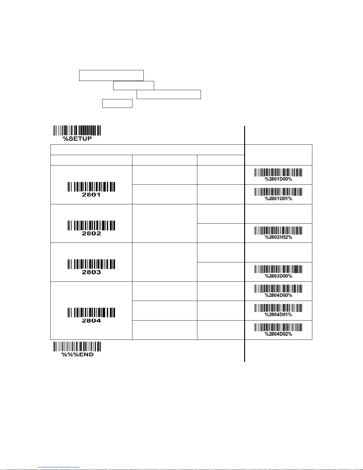
64
4-26 GS1 DataBar Limited
Read:
Format
16 Data digits
Code ID setting: Refer to Code ID setting of
“4-7 UPC-A”
.
Insertion group selection: Refer to Insertion group selection of
“4-7 UPC-A”
.
Conversion: Refer to Conversion of
“4-25 GS1 DataBar (GS1 DataBar Truncated)”
.
SETUP Multiple-scan setting
Single-scan setting
Option barcode
Option
Alpha. value
Read
Disable
00
Enable
01*
Code ID setting
00-FF16
(ASCII)
00-FF16
<R >*
Insert group selection
00-44
(00:None)
00-44
00*
Conversion
None
00*
UCC/EAN 128
01
UPC-A or EAN-13
02
END
Page 71
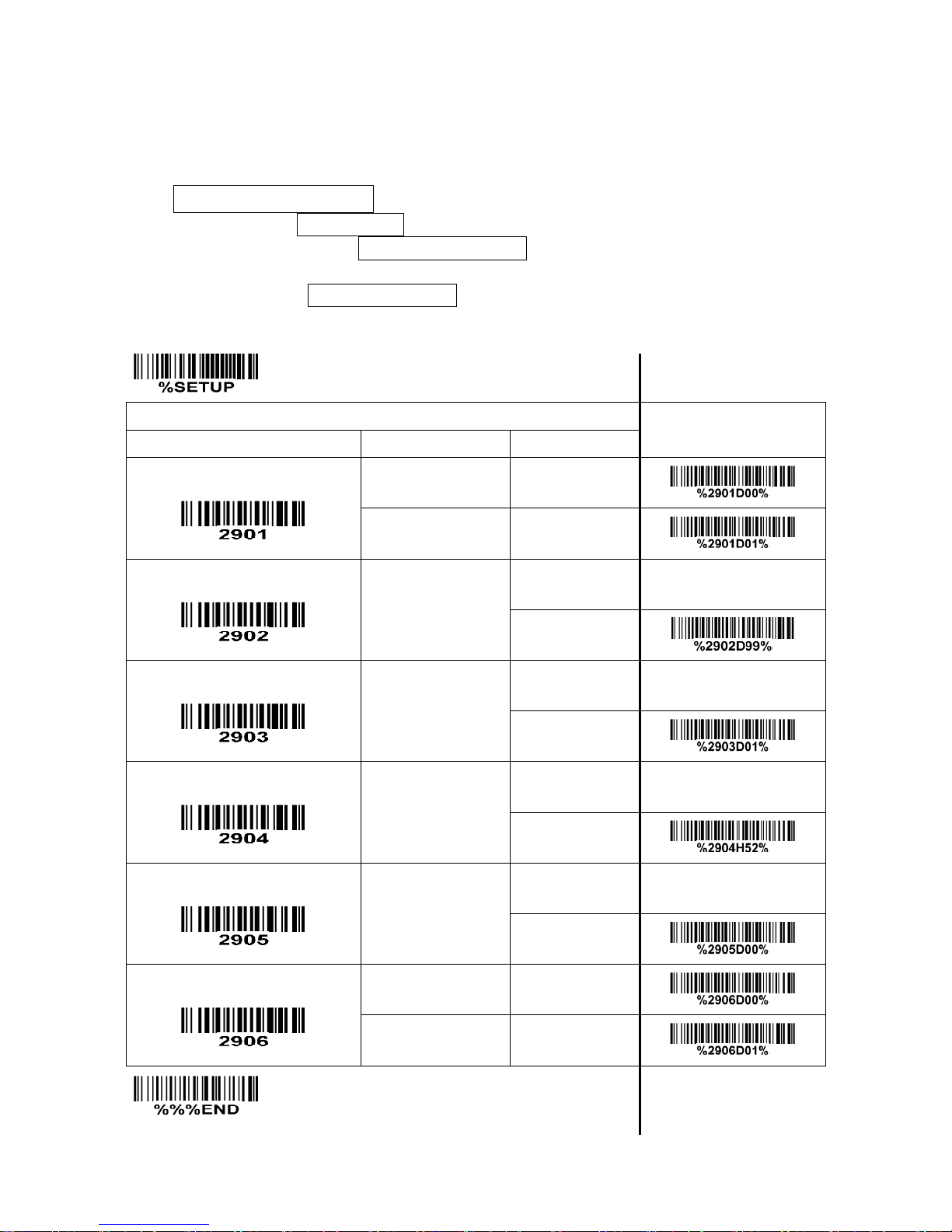
65
4-27 GS1 DataBar Expanded
Read:
Format
Data characters (variable)
Code ID setting: Refer to Code ID setting of
“4-7 UPC-A”
.
Insertion group selection: Refer to Insertion group selection of
“4-7 UPC-A”
.
Conversion:
UCC/EAN 128- Refer to Code ID transmission of
“4-30 String transmission”
, ]Cm will be identified as
AIM ID.
SETUP
Multiple-scan setting
Single-scan setting
Option bar code
Option
Alpha. value
Read
Disable
00
Enable
01*
Max. code length
00-99
00-99
99*
Min. code length
00-99
00-99
01*
Code ID setting
00-FF16
(ASCII)
00-FF16
<R >*
Insert group selection
00-44
(00:None)
00-44
00*
Conversion
None
00*
UCC/EAN 128
01
END
Page 72
66
4-28 G1-G4 & FN1 substitution string setting
Format of barcode data transmission
Prefix
Code name
Preamble
Code ID
Code length
Code data
Code ID
Postamble
Suffix
Suffix string setting: The <enter > key is represented in different ASCII when it is applied by different OS.
For a Windows/DOS OS, <enter> is represented as <CR><LF> (0x0D 0x0A); for an Apple MAC OS,
<enter> is represented as <CR> (0x0D); for a Linux/Unix OS, <enter> is represented as <LF> (0x0A).
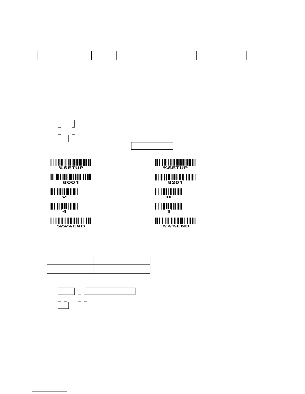
Prefix/Suffix string setting & Preamble/Postamble string setting:
They are appended to the data automatically when a barcode is decoded.
Example: Add a symbol of “$” as a prefix for all type of barcode.
Steps:
1) Look up in the ASCII table to find the value of $→24.
2) Scan SETUP and Prefix string setting barcode.
3) Scan 2 and 4 barcode.
4) Scan END barcode.
5) Refer to
“4-30 String transmission”
, set Prefix transmission to be Enable.
Scanning steps: Scan the following barcodes in order.
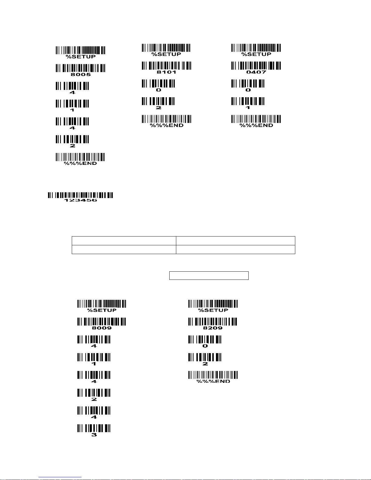
Insert G1/G2/G3/G4 string setting: The scanner offers 4 positions and 4 character strings to insert
among the barcode data string.
Example: Set G1 string to be “AB”.
Original code data
“1 2 3 4 5 6”
Output code data
“1 2 A B 3 4 5 6”
Steps:
1) Look up in the ASCII table to find the value of A→41, B→42.
2) Scan SETUP and Insert G1 string setting barcode “8005”.
3) Scan 4, 1 and 4, 2 barcode.
4) Scan END barcode.
5) Refer to the chapter of
“4-29 G1-G4 string position & Code ID position”
.
6) Refer to the chapter of
“4-5 Scan mode & some global settings”
.
Page 73
67
Testing barcode:
FN1 substitution string setting: The FN1 character (0x1D) in an UCC/EAN128 barcode, or a Code 128
barcode, or a GS1 DataBar barcode can be substituted with a defined string.
Example: Set FN1 substitution string to be “ABCD”.
Original code data (hexadecimal)
“31 1D 32 1D 33 1D 34 1D 35”
Output code data (hexadecimal)
“31 41 32 42 33 43 34 44 35”
Steps:
1) Set FN1 substitution string to be ABCD.
2) Refer to
“4-30 String transmission”
, enable FN1 substitution transmission.
In this example, because the interface of the scanner is RS232, so set “8209” to 02.
Scanning steps: Scan the following barcodes in order.
Page 74

68
Testing barcode:
Page 75
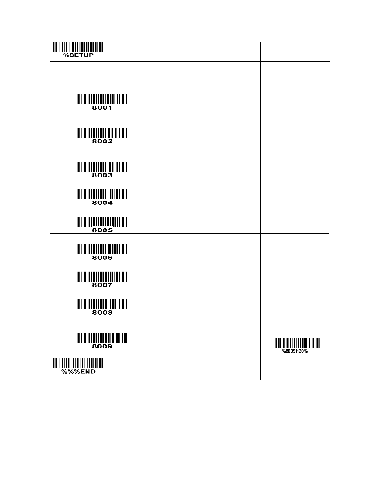
69
SETUP Multiple-scan setting
Single-scan setting
Option bar code
Option
Alpha. value
Prefix string setting
0-22 characters
(Default: None)
00-FF16
Suffix string setting
0-22 characters
00-FF16
<ENTER>
0D0A*
Preamble string setting
0-22 characters
(Default: None)
00-FF16
Postamble string setting
0-22 characters
(Default: None)
00-FF16
Insert G1 string setting
0-22 characters
(Default: None)
00-FF16
Insert G2 string setting
0-22 characters
(Default: None)
00-FF16
Insert G3 string setting
0-22 characters
(Default: None)
00-FF16
Insert G4 string setting
0-22 characters
(Default: None)
00-FF16
FN1 substitution string setting
0-4 characters
00-FF16
<SP>
20*
END
Page 76
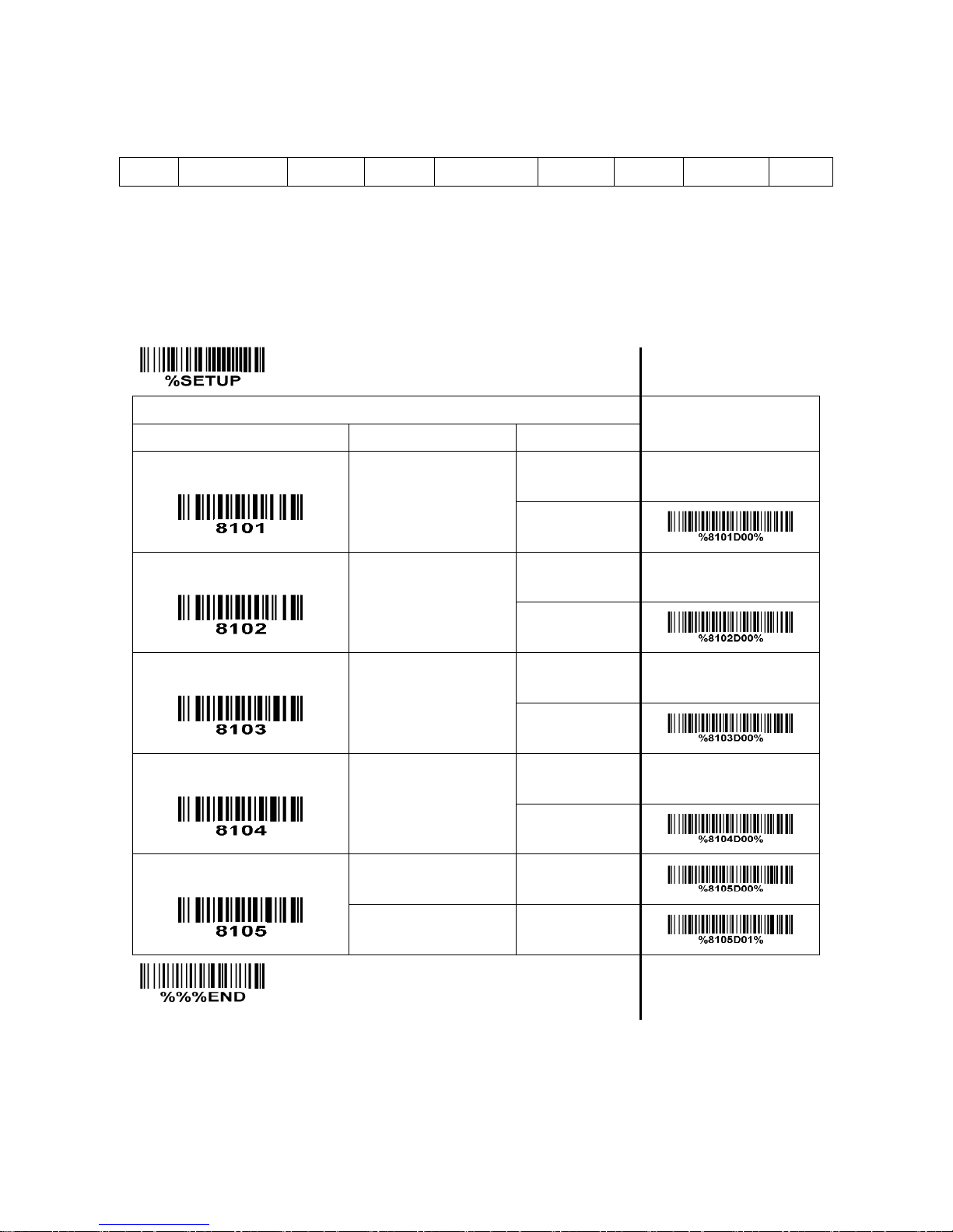
70
4-29 G1-G4 string position & Code ID position
Format of barcode data transmission
Prefix
Code name
Preamble
Code ID
Code length
Code data
Code ID
Postamble
Suffix
Insert G1/G2/G3/G4 string position: The scanner offers 4 positions to insert strings among the symbol. In
case of the insertion position is greater than the length of the symbol, the insertion of string is not
effective.
Code ID position: It is allowed to select different positions of code ID placement.
SETUP Multiple-scan setting
Single-scan setting
Option bar code
Option
Alpha. value
Insert G1 string position
00-99
00-99
00*
Insert G2 string position
00-99
00-99
00*
Insert G3 string position
00-99
00-99
00*
Insert G4 string position
00-99
00-99
00*
Code ID position
Before code data
00*
After code data
01
END
Page 77
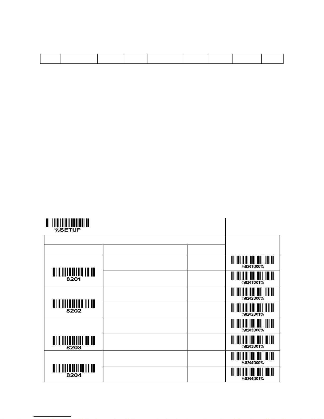
71
4-30 String transmission
Format of barcode data transmission
Prefix
Code name
Preamble
Code ID
Code length
Code data
Code ID
Postamble
Suffix
Prefix transmission: By setting Enable, prefix will be appended before the data transmitted.
Suffix transmission: By setting Enable, suffix will be appended after the data is transmitted.
Code name transmission: By setting Enable, code name will be transmitted before code data.
Preamble transmission: By setting Enable, preamble will be appended before the data transmitted.
Postamble transmission: By setting Enable, postamble will be appended after the data is transmitted.
Code ID transmission: Code ID can be transmitted in the format of either Proprietary ID or AIM ID. Refer
to the chapter of
“1-2 Default settings for various types of barcode”
.
Code length transmission: The length of code data string can be transmitted before the code data when
Enable is selected. The length is represented by a number with two digits.
Case conversion: The characters within code data or the whole output string can be set in either upper
case or lower case.
FN1 substitution transmission: The scanner supports a FN1 substitution feature for keyboard wedge,
USB and RS-232 interface. The replacement string of FN1 can be chosen by user (see chapter of
“4-28
G1-G4 & FN1 substitution string setting”
).
SETUP
Multiple-scan setting
Single-scan setting
Option bar code
Option
Alpha. value
Prefix transmission
Disable
00*
Enable
01
Suffix transmission
Disable
00
Enable
01*
Code name
transmission
Disable
00*
Enable
01
Preamble transmission
Disable
00*
Enable
01
Page 78
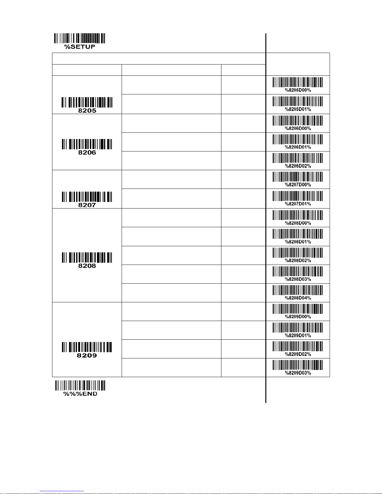
72
SETUP
Multiple-scan setting
Single-scan setting
Option bar code
Option
Alpha. value
Postamble
transmission
Disable
00*
Enable
01
Code ID transmission
Disable
00*
Proprietary ID
01
AIM ID
02
Code length
transmission
Disable
00*
Enable
01
Case conversion
Disable
00*
Upper (data only)
01
Lower (data only)
02
Upper (whole string)
03
Lower (whole string)
04
FN1 substitution
transmission
Disable
00*
Keyboard wedge/USB
01
RS232
02
Keyboard wedge/USB/RS232
03
END
Page 79

73
5 Serial Communication Interface
Note: SCI is supported for RS232 interface or USB virtual COM only.
This section describes the system requirements of the Serial Communication Interface (SCI), which
provides a communication link between a scanner and a host via RS232 interface or USB virtual COM.
SCI allows the host to configure the scanner. All communication between the scanner and the host occur
over the hardware interface lines using the SCI protocol.
The host and the scanner exchange messages in packets. A packet is a collection of bytes framed by
the proper SCI protocol formatting bytes. The maximum number of bytes per packet allowed by the SCI
protocol for any transaction is 257 (255 bytes of data + 2 bytes of checksum).
Decode data may be sent as ASCII data (unpacked), or as part of a larger message (packeted),
depending on the scanner configuration.
Table 5-1 SCI commands
No.
Command name
Operation code
Description
1
BEEP
0x42(‘B’)
Sound the beeper.
2
CMD_ACK
0x59(‘Y’)
Positive acknowledgement.
3
CMD_NAK
0x4E(‘N’)
Negative acknowledgement.
4
DECODE_DATA
0x50(‘P’)
Decode data in SCI packet format.
5
LED_CTR
0x4C(‘L’)
Turn on/off the led.
6
REQUEST_REVISION
0x56(‘V’)
Request scanner’s software revision.
7
REPLY_REVISION
0x52(‘R’)
Reply scanner’s software revision.
8
START_DECODE
0x53(‘S’)
Tell scanner to attempt to decode a barcode.
9
STOP_DECODE
0x45(‘E’)
Tell scanner to abort a decode attempt.
10
PARAM_DEFAULT
0x25(‘%’)
Load scanner’s default settings.
11
PARAM_REQUEST
0x3F(‘?’)
Request values of certain parameters.
12
PARAM_SEND
0x23(‘#’)
Parameter transmission.
13
CUSTOM_DEFAULTS
0x26(‘&’)
Custom defaults option to write/restore.
14
CMD_RESTART
0x5e(‘^’)
Tell scanner to restart as soon as possible.
15
WAKUP
N/A
Wakeup scanner after it has been in sleep state.
16
CMD_OUTPUTBUFFER_CTR
0x62(‘b’)
Control output buffer.
Page 80

74
5-1 SCI message formats
The general packet format for SCI message is as following:
Length
Opcode
Status
Data
Checksum
Table 5-2 lists the descriptions of fields that occur in all messages. These descriptions are repeated for
each opcode. For messages that use the Data field, the specific type of data is described in that field in
later sections.
Table 5-2 Field descriptions
Field name
Format
Size
Description
Length
Information length
(not including checksum)
1 Byte
Length of message not including the check sum
bytes. Maximum value is 0xFF.
Opcode
See
Table 5-1
for details
1 Byte
Identifies this opcode type.
Status
Bit 0: Identifies transmit status
Bit 5-1: Parameter property
(For PARAM_REQUEST and
PARAM_SEND only.)
Bit 6: Change type(apply to parameter
transmission)
Bit 7: Command source
1 Byte
Bit 0:
0 = First time packet is sent
1 = Subsequent transmission attempts
Bit 5-1:
0=Maximum parameter value
1= Minimum parameter value
2= Permanent parameter value
3= Temporary parameter value
4=Default 0 parameter value
5=Custom default parameter value
6-15=Reserved
Bit 6:
0 = Temporary change
1 = Permanent change
Bit 7:
0=Command is from the scanner
1=Command is from the host
All unused bits recommend to be set to 0.
Data
See individual sections for details
Variable
number
of Bytes
Checksum
2’s complement sum of message
contents excluding checksum
2 Bytes
Checksum of message formatted as High-Byte
Low-Byte
Note: The checksum is a 2 byte checksum and must be sent as High-Byte followed by Low-Byte.
Checksum = 0x10000 - Length - Opcode - Status - Data.
Page 81
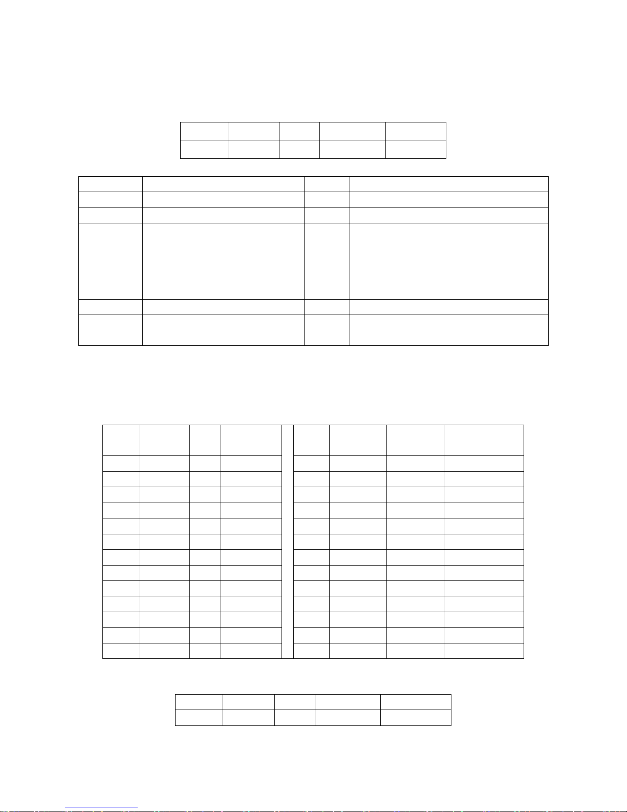
75
5-2 BEEP
Description: Ask the scanner to sound the beeper.
Packet Format
Length
Opcode
Status
Beep Code
Checksum
0x04
0x42
Field Descriptions
Field Name
Format
Size
Description
Length
0x04
1 Byte
Length Field
Opcode
0x42
1 Byte
Identifies this opcode type.
Status
Bit 0: Identifies transmit status
Bit 6-1: Unused
Bit 1-7: Command source
1 Byte
Bit 0:
0=First time packet is sent
1= Subsequent transmission attempts
Bit 7: always be 1(message is from the host)
All unused bits recommend to be set to 0.
Beep Code
See
Table 5-3
.
1 Byte
Number that identifies a beep sequence.
Checksum
2's complement sum of message
contents excluding checksum.
2 Bytes
Checksum of message.
This command instructs the scanner to sound the beep sequence indicated by the Beep Code field.
In Table 5-3, Duration (a relative term) is the length of a sound, Pitch (a relative term) is the pitch of the
sound, and Number of Beeps indicates the times of a repeated beep pitch at the specified duration.
Table 5-3 Beep code definitions
Beep
Code
Duration
(ms)
Pitch
No. of
beeps
Beep
Code
Duration
(ms)
Pitch
No. of beeps
0x00
72
High
1 (Short)
0x0D
1569
High
4 (Long)
0x01
193
High
2 (Short)
0x0E
2011
High
5 (Long)
0x02
315
High
3 (Short)
0x0F
241
Low
1 (Long)
0x03
436
High
4 (Short)
0x10
684
Low
2 (Long)
0x04
558
High
5 (Short)
0x11
1126
Low
3 (Long)
0x05
72
Low
1 (Short)
0x12
1569
Low
4 (Long)
0x06
193
Low
2 (Short)
0x13
2011
Low
5 (Long)
0x07
315
Low
3 (Short)
0x14
382
Hi-Lo-Hi-Lo
4 (Fast Warble)
0x08
436
Low
4 (Short)
0x15
965
Hi-Lo-Hi-Lo
4 (Slow Warble)
0x09
558
Low
5 (Short)
0x16
191
Hi-Lo
2 (Mix 1)
0x0A
241
High
1 (Long)
0x17
191
Lo-Hi
2 (Mix 2)
0x0B
684
High
2 (Long)
0x18
292
Hi-Lo-Hi
3 (Mix 3)
0x0C
1126
High
3 (Long)
0x19
282
Lo-Hi-Lo
3 (Mix 4)
For example: Host sends beep command to scanner (Beep code: 0x06)
Length
Opcode
Status
Beep Code
Checksum
0x04
0x42
0x80
0x06
0xFF 0x34
The method of calculating Checksum:
Page 82

76
Checksum=0x10000-0x04-0x42-0x80-0x06.
Host Requirements
The host sends this command to cause the scanner to beep.
Scanner Requirements
When the scanner receives this command, it beeps the sequence provided in the Beep code field. If
ACK/NAK handshaking is enabled and a valid beep code (see
Table 5-3
) is received, the scanner
replies ACK. Otherwise it sends NAK_DENIED (see
“5-4 CMD_NAK”
).
Page 83

77
5-3 CMD_ACK
Description: Positive acknowledgment of received packet.
Packet Format
Length
Opcode
Status
Checksum
0x03
0x59
Field Descriptions
Field name
Format
Size
Description
Length
0x03
1 Byte
Length of Field
Opcode
0x59
1 Byte
Identifies the command being sent.
Status
Bit 0: Identifies transmit status
Bit 6-1: Unused
Bit 7: Command source
1 Byte
Bit 0:
0=First time packet is sent
1= Subsequent transmission attempts
Bit 7:
0=Command is from the scanner
1=Command is from the host
All unused bits recommend to be set to 0.
Checksum
2’s complement sum of message
contents excluding checksum
2 Bytes
Checksum of message
CMD_ACK message is sent to the SCI packet transmitter when the received packet passes the
checksum check and no negative acknowledgment conditions apply. If the data to be sent is in response
to a command (e.g. REQUEST_REVISION), CMD_ACK message is not in need.
ACK/NAK handshaking can be disabled, but this is not recommended.
It is not necessary to respond to a valid ACK or NAK message.
For example: Scanner sends ACK.
Length
Opcode
Status
Checksum
0x03
0x59
0x00
0xFF 0xA4
Host Requirements
The host must send a CMD_ACK or response data within the programmable Response delay to
acknowledge receipt of all messages, unless noted otherwise in the message description section.
Scanner Requirements
If the scanner does not receive an ACK within Response delay, it sends the previous message again.
The scanner retries twice more (with the retransmit status bit set) before declaring a transmit error.
Page 84

78
5-4 CMD_NAK
Description: Negative acknowledgment of received packet
Packet Format
Length
Opcode
Status
Cause
Checksum
0x04
0x4E
Field Descriptions
Field Name
Format
Size
Description
Length
0x04
1 Byte
Length Field
Opcode
0x4E
1 Byte
Identifies the opcode type.
Status
Bit 0: Identifies transmit status
Bit 6-1: Unused
Bit 7: Command source
1 Byte
Bit 0:
0=First time packet is sent
1= Subsequent transmission attempts
Bit 7:
0=Command is from the scanner
1=Command is from the host
All unused bits recommend to be set to 0.
Cause
Reason code
1 Byte
Identifies the reason the NAK occurred:
01=NAK_OVERFLOW(Data Overflow, with
baud rate of 115200b/s)
02=NAK_RESEND(Checksum failure)
04=NAK_BAD_CONTEXT(Unexpected or
unknown message)
08=NAK_DENIED(Host denies executing the
require of Opcode)
40=NAK_NO_PARA (The parameter requests
to be changed doesn’t exist)
80=NAK_OUT_OF_RANGE(The parameter
requests to be changed exceeds the
range)
Checksum
2's complement sum of message
contents excluding checksum.
2 Byte
Checksum of message.
This message is sent when the received packet fails the checksum verification or some error occurred
while handling the message.
ACK/NAK handshaking can be disabled, but this is not recommended.
It is not necessary to respond to a valid ACK or NAK message.
Page 85

79
For example: Scanner sends NAK.
Length
Opcode
Status
Cause
Checksum
0x04
0x4E
0x00
0x40
(the parameter requested is not exist)
0xFF 0x6E
Table 5-4 describes NAK types supported by the scanner.
Table 4-5 Scanner-supported NAK types
NAK Type
Meaning
Receiver Action
NAK_OVERFLOW
Data Overflow
While receiving message with the baud rate
115200B/s, scanners receive buffer may occur
overflow. If the message length is greater than
7, the scanner fails to receive and process the
data without delay, and reply NAK_OVERFLOW
to host.
NAK_RESEND
Checksum incorrect.
Ensure checksum is correct. Send packet again
with resend bit set (with the retransmit status bit
set).
NAK_BAD_CONTEXT
The parameter want to be changed
do not exist
Do not send the same message again. Ensure
the correct message is sent.
NAK_DENIED
The parameter want to be changed
exceeds the range
NAK_NO_PARA
Host does not recognize the
command.
NAK_OUT_OF_RANGE
Host is unable to comply with the
requested command (e.g., scan
mode setting code is out of range).
Page 86

80
5-5 DECODE_DATA
Description: Decode data in SCI packet format
Packet Format
Length
Opcode
Status
Decode Data
Checksum
0x50
Field Descriptions
Field Name
Format
Size
Description
Length
Length of message
(not including checksum).
1 Byte
Length Field
Opcode
0x50
1 Byte
Identifies the opcode type.
Status
Bit 0: Identifies transmit status
Bit 6-1: Unused
Bit 7: Command source
1 Byte
Bit 0:
0=First time packet is sent
1= Subsequent transmission attempts
Bit 7: always be 0(message is from the
scanner)
All unused bits recommend to be set to
0.
Decode Data
<data>
Variable
Data is decoded data including prefix
and suffix sent in ASCII format.
Checksum
2's complement sum of message
contents excluding checksum.
2 Bytes
Checksum of message.
When the scanner uses this opcode Decode data packet format is selected to send decoded barcode
data to the host. The decoded data is contained in the Decode Data field.
For example: the decode data is “1234”, the DECODE_DATA message sent to host is as following.
Length
Opcode
Status
Decode Data
Checksum
0x07
0x50
0x00
0x31 0x32 0x33 0x34
0xFE 0xDF
Host Requirements
If ACK/NAK handshaking is enabled, the host responds ACK to the scanner when received correct data
packet.
Scanner Requirements
Decode data is sent in this format if Decode data packet format is selected via parameter. The host
responds to this message with a CMD_ACK, if ACK/NAK handshaking is enabled.
Page 87

81
5-6 LED_CTR
Description: LED control, it can control LED0 (red) and LED1 (blue).
Packet Format
Length
Opcode
Status
LED Option
LED Status
Checksum
0x05
0x4C
Field Descriptions
Field Name
Format
Size
Description
Length
0x05
1 Byte
Length Field
Opcode
0x4C
1 Byte
Identifies the opcode type.
Status
Bit 0: Identifies transmit status
Bit 6-1: Unused
Bit 7: Command source
1 Byte
Bit 0:
0=First time packet is sent
1= Subsequent transmission attempts
Bit 7: always be 1(message is from the host)
All unused bits recommend to be set to 0.
LED Option
Bit 0-7: Each bit controls one LED. And
it can control multiple LEDs at the
same time.
1 Byte
Bit 0:
1=Control LED0
0= Don’t control LED0
Bit 1:
1=Control LED1
0= Don’t control LED1
Bit2-7: reserved to be 0.
LED
Status
Bit 0-7: Each bit controls one LED’s
status
1 Byte
Bit 0:
1=LED0 ON
0=LED0 OFF
Bit 1:
1=LED1 ON
0=LED1 OFF
Bit2-7: reserved to be 0.
Checksum
2's complement sum of message
contents excluding checksum.
2 Bytes
Checksum of message.
For example: Host controls LED0 and LED1 at the same time (turn on LED0 and turn off LED1).
Length
Opcode
Status
LED Option
LED Status
Checksum
0x05
0x4C
0x80
0x03
0x02
0xFF 0x2A
Host Requirements
None.
Scanner Requirements
Scanner turns on LED0 and turns off LED1.
Page 88

82
5-7 REQUEST_REVISION
Description: Request the software revision string from the scanner
Packet Format
Length
Opcode
Status
Checksum
0x03
0x56
Field Descriptions
Field Name
Format
Size
Description
Length
0x03
1 Byte
Length Field
Opcode
0x56
1 Byte
Identifies this opcode type.
Status
Bit 0: Identifies transmit status
Bit 6-1: Unused
Bit 7: Command source
1 Byte
Bit 0:
0=First time packet is sent
1= Subsequent transmission
attempts
Bit 7: always be 1(message is from
the host)
All unused bits recommend to be set
to 0.
Checksum
2's complement sum of message contents
excluding checksum.
2 Bytes
Checksum of message.
For example:
Length
Opcode
Status
Checksum
0x03
0x56
0x80
0xFF 0x27
Host Requirements
The host sends this message to request revision information from the scanner. The scanner responds
with REPLY_REVISION.
Scanner Requirements
The scanner sends its revision string to the host. See
“5-8 REPLY_REVISION”
.
Page 89
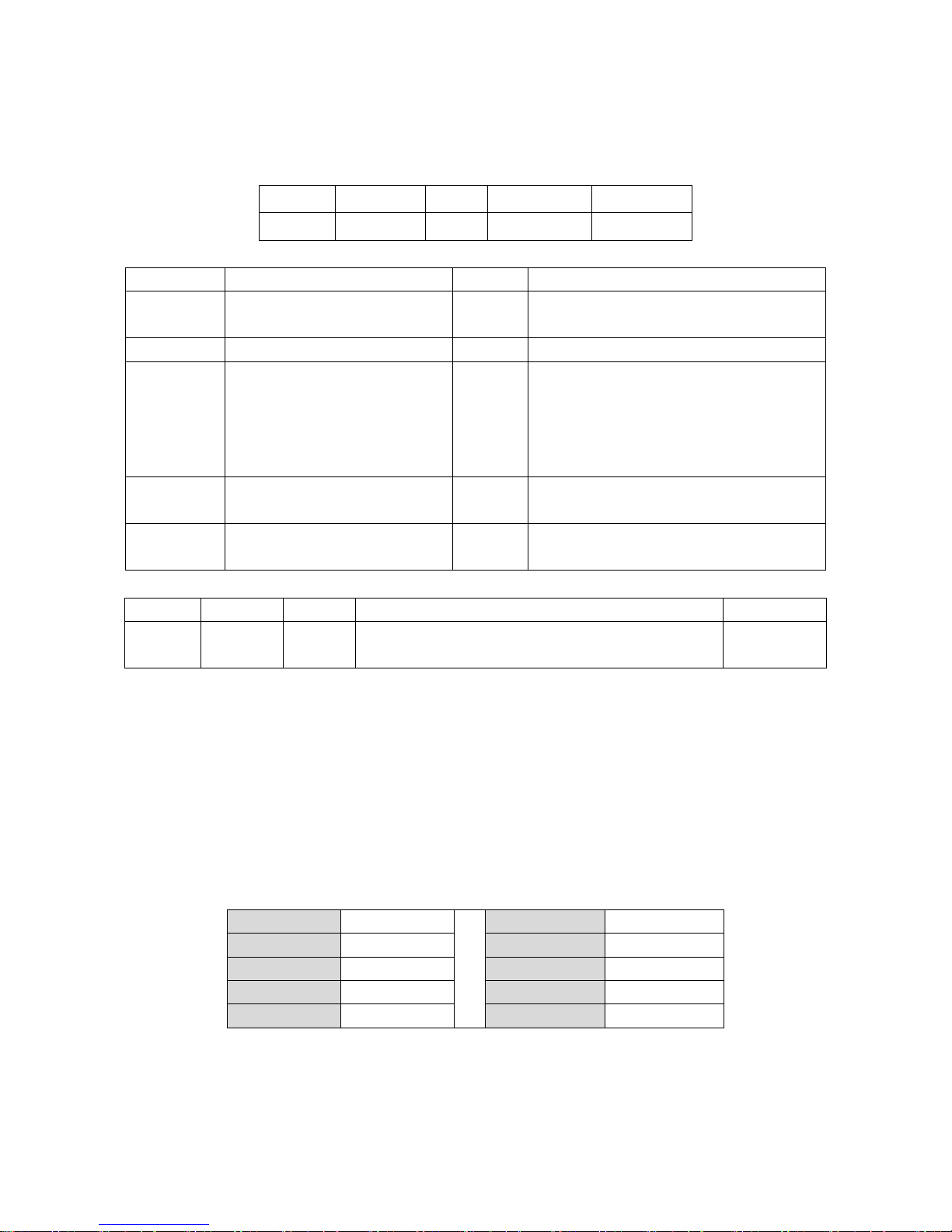
83
5-8 REPLY_REVISION
Description: Reply to REQUEST_REVISION command with software revision string
Packet Format
Length
Opcode
Status
Revision
Checksum
0x52
Field Descriptions
Field Name
Format
Size
Description
Length
Length of message
(not including checksum).
1 Byte
Length Field
Opcode
0x52
1 Byte
Identifies this opcode type.
Status
Bit 0: Identifies transmit status
Bit 6-1: Unused
Bit 7: Command source
1 Byte
Bit 0:
0=First time packet is sent
1= Subsequent transmission
Bit 7: always be 0(message is from the scanner)
All unused bits recommend to be set to 0.
Revision
ASCII data
variable
Software revision in ASCII (see following for
details).
Checksum
2's complement sum of message
contents excluding checksum.
2 Bytes
Checksum of message.
For example: If the HW/SW_REVISION is “FS580_HW1.0_SW1.0”, the REPLY_REVISION message is:
Length
Opcode
Status
Revision
Checksum
0x16
0x52
0x00
0x46 0x53 0x35 0x38 0x30 0x5F 0x48 0x57 0x31 0x2E 0x30
0x5F 0x53 0x57 0x31 0x2E 0x30 0x20 0x2D
0xFA 0xF0
Host Requirements
None.
Scanner Requirements
The scanner sends its Revision field data string to the host in the following format:
HW/SW_REVISION<space>SCANNER_ID
Resolving:
HW/SW_RIVISION: the version string of hardware and software information.
SCANNER_ID: the ID information of scanner.
Scanner ID Listed:
Scanner ID
Product
Scanner ID
Product
0x2C
FS380
0x1A
ME4144
0x2D
FS580
0x1B
ES4200
0xAB
uE988
0x1C
ES4290
0xAB
uE966
0x3A
ME5110
Page 90

84
5-9 START_DECODE
Description: Ask the scanner to attempt to decode a barcode
Packet Format
Length
Opcode
Status
Checksum
0x03
0x53
Field Descriptions
Field Name
Format
Size
Description
Length
0x03
1 Byte
Length Field
Opcode
0x53
1 Byte
Identifies this opcode type.
Status
Bit 0: Identifies transmit status
Bit 6-1: Unused
Bit 7: Command source
1 Byte
Bit 0:
0=First time packet is sent
1= Subsequent transmission
Bit 7: always be 1(message is from
the host)
All unused bits recommend to be set
to 0.
Checksum
2's complement sum of message contents
excluding checksum.
2 Bytes
Checksum of message.
This command asks the scanner to start a scan and a decode session. The decode session ends with a
successful decode, or a scan session time-out, or a STOP_DECODE command.
For example: Host sends START_DECODE command
Length
Opcode
Status
Checksum
0x03
0x53
0x80
0xFF 0x2A
Host Requirements
None.
Scanner Requirements
The scanner must attempt decode a barcode once whatever the scan mode is, after receiving the
START_DECODE command.
Page 91

85
5-10 STOP_DECODE
Description: Ask scanner to abort a decode attempt
Packet Format
Length
Opcode
Status
Checksum
0x03
0x45
Field Descriptions
Field Name
Format
Size
Description
Length
0x03
1 Byte
Length Field
Opcode
0x45
1 Byte
Identifies this opcode type.
Status
Bit 0: Identifies transmit status
Bit 6-1: Unused
Bit 7: Command source
1 Byte
Bit 0:
0=First time packet is sent
1= Subsequent transmission
Bit 7: always be 1(message is from
the host)
All unused bits recommend to be set
to 0.
Checksum
2's complement sum of message contents
excluding checksum.
2 Bytes
Checksum of message.
This command asks the scanner to stop a scan and a decode attempt.
For example:
Length
Opcode
Status
Checksum
0x03
0x45
0x80
0xFF 0x38
Host Requirements
None.
Scanner Requirements
The scanner stop decoding operation, after receiving a STOP_DECODE command (if ACK/NAK
handshaking is enabled, the scanner will respond with an ACK or NAK).
Note: When Scan mode is Continuous, after receiving STOP_DECODE command, the scanner will not
stop scanning.
Page 92

86
5-11 PARAM_DEFAULTS
Description: Set the parameters to default values
Packet Format
Length
Opcode
Status
Setting type
Checksum
0x04
0x25
Field Descriptions
Field Name
Format
Size
Description
Length
0x04
1 Byte
Length Field
Opcode
0x25
1 Byte
Identifies this opcode type.
Status
Bit 0: Identifies transmit status
Bit 6-1: Unused
Bit 7: Command source
1 Byte
Bit 0:
0=First time packet is sent
1= Subsequent transmission
Bit 7: always be 1(message is from the host)
All unused bits recommend to be set to 0.
Setting type
Default setting type
1 Byte
0-255.
0: Default setting 0 (Mindeo standard)
Checksum
2's complement sum of message
contents excluding checksum.
2 Bytes
Checksum of message.
For example: return all parameters to the factory default setting values.
Length
Opcode
Status
Setting type
Checksum
0x04
0x25
0x80
0x00
0xFF 0x57
Host Requirements
The host sends this command to reset the scanner’s parameter settings to the factory default values.
Scanner Requirements
Upon receiving this command, the scanner’s resets all parameters (except Scan mode) to the factory
default values. The behavior is the same as scanning factory defaults configuration barcode, see section
“11 Return default parameters & firmware version”
.
Page 93
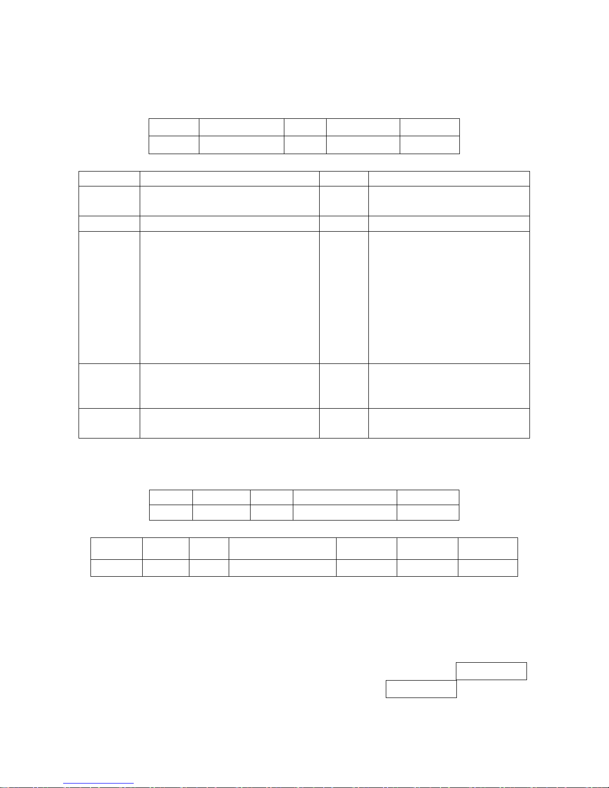
87
5-12 PARAM_REQUEST
Description: Request values of selected parameters
Packet Format
Length
Opcode
Status
Parameter code
Checksum
0x3F
Field Descriptions
Field Name
Format
Size
Description
Length
Length of message
(not including checksum).
1 Byte
Length Field
Opcode
0x3F
1 Byte
Identifies this opcode type.
Status
Bit 0: Identifies transmit status
Bit 5-1: Unused
Bit 6: Unused
Bit 7: Command source
1 Byte
Bit 0:
0 = First time packet is sent
1 = Subsequent transmission attempts
Bit 5-1: Reserved
Bit 6: Reserved
Bit 7: always be 1(message is from the
host)
All unused bits recommend to be set to
0.
Request
Data
Parameter1, Parameter2, …
Variable
Each parameter code has 4 bytes; Host
can request several parameters at the
same time.
Checksum
2's complement sum of message contents
excluding checksum.
2 Bytes
Checksum of message.
The host uses this message to request some specific parameters from the scanner.
For example: the value of scanner parameter “0301” is 01, when host queries value of the parameter
“0301”, the PARAM_REQUEST sent by host is as following:
Length
Opcode
Status
Parameter code
Checksum
0x07
0x3F
0x80
0x30 0x33 0x30 0x31
0xFE 0x76
the PARAM_SEND responded by scanner is as following:
Length
Opcode
Status
Parameter code
Data type
parameter
Checksum
0x0A
0x23
0x00
0x30 0x33 0x30 0x31
0x44
0x30 0x31
0xFE 0x6A
Host Requirements
The host requests the scanner’s current values for specific parameters by listing the parameter codes in
the Request Data field. If the host asks for a parameter which is not supported by the scanner, the
scanner responds with NAK.
The scanner’s response to this command is PARAM_SEND, not ACK. Depending on the time-out setting,
and the number of parameters requested, this reply may fall outside the programmable Response delay.
If this occurs, this is not a time-out error. To compensate, increase the Response delay.
Scanner Requirements
When the scanner receives this message, it processes the information by formatting a PARAM_SEND
Page 94

88
message containing all requested parameters supported and their values. The programmable Response
delay can be exceeded when processing this message, depending on the time-out set and the number
of parameters requested.
Page 95

89
5-13 PARAM_SEND
Description: the command performs two optional operations:
1) The scanner responds to a PARAM_REQUEST.
2) The host demands scanner to change particular parameter values.
Packet Format
Length
Opcode
Status
Parameter
code
Data
type
Parameter
value
…
Checksum
0x23
Field Descriptions
Field Name
Format
Size
Description
Length
Length of message
(Not including checksum).
1 Byte
Length Field
Opcode
0x23
1 Byte
Identifies this opcode type.
Status
Bit 0: Identifies transmit status
Bit 5-1: Unused
Bit 6: Change type
Bit 7: Command source
1 Byte
Bit 0:
0 = First time packet is sent
1 = Subsequent transmission attempts
Bit 5-1:Reserved
Bit 6:
0 = Temporary change
1 = Permanent change
Bit 7:
0=Command is from the scanner
1=Command is from the host
All unused bits recommend to be set to 0.
Parameter Code
Parameter code
4 Bytes
Each parameter code has 4 bytes
Data type
Note
‘H’ (0x48) or ‘D’ (0x44) or ‘S’
(0x53)
1 Byte
‘ H’: The type of the parameter value is
hexadecimal, the length of parameter
value is 2 bytes.
‘D’: The type of the parameter value is decimal,
the length of parameter value is 2 bytes.
‘S’: The parameter value is a string ended with
‘\0’ (0x00), the length of parameter value is
1-23 bytes
Parameter Value
Variable
1-23
… Variable
Next parameter(parameter code,
data type, parameter value)….
Checksum
2's complement sum of
message contents excluding
checksum.
2 Bytes
Checksum of message.
Note: When data type is ‘S’, it supports 8001-8009 option barcode only.
This message is sent by the scanner in response to the PARAM_REQUEST message, or by the host to
change the scanner’s parameter values.
Page 96
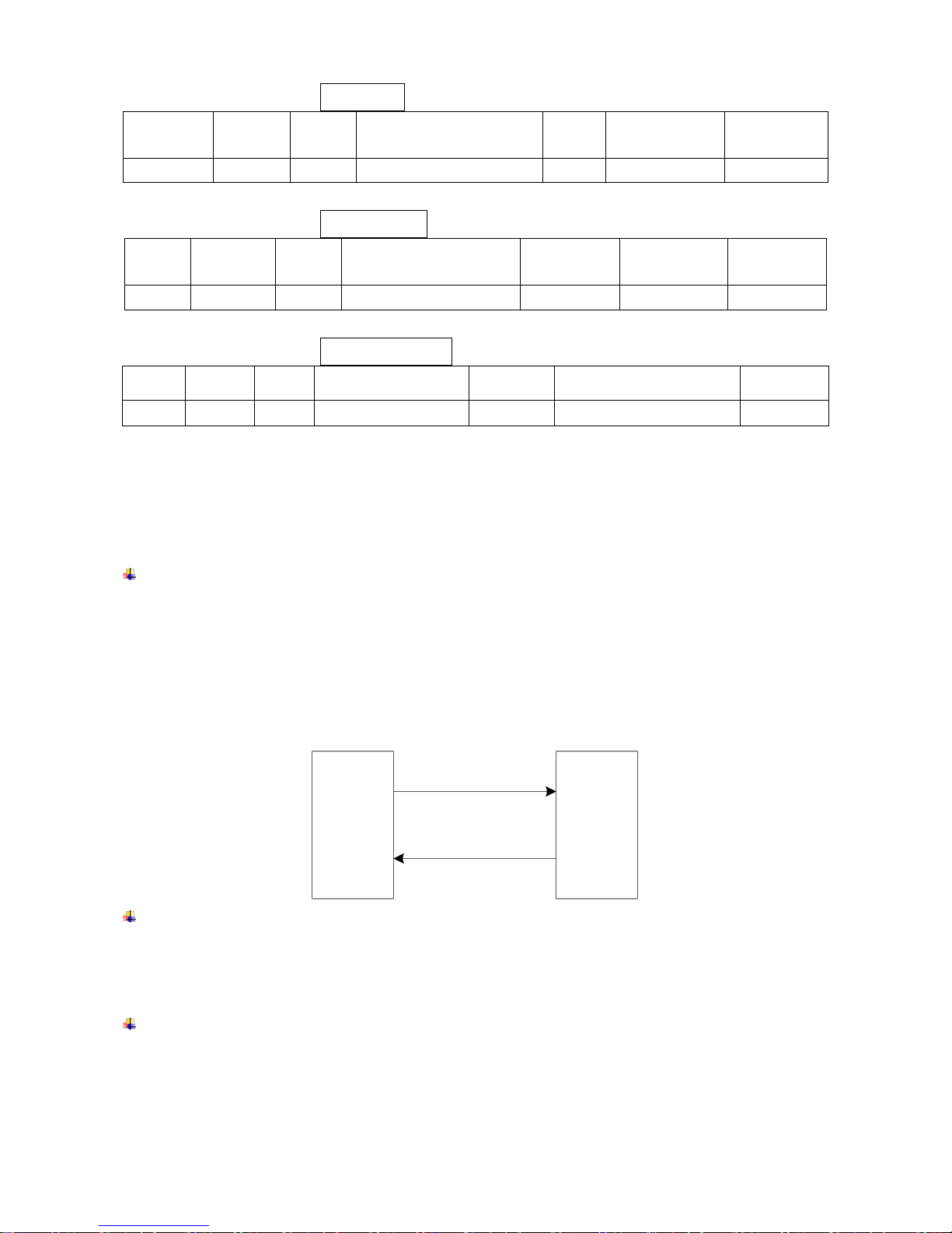
90
Example 1: to set parameter Flow control to be None (see
“4-3 RS232 interface”
).
Length
Opcode
Status
Parameter code
Data
type
Parameter
value
Checksum
0x0A
0x23
0xC0
0x30 0x33 0x30 0x31
0x44
0x30 0x30
0xFD 0xAB
Example 2: to set parameter Code ID setting of UPC-A to be U (0x55).
Length
Opcode
Status
Parameter code
Data type
Parameter
value
Checksum
0x0A
0x23
0xC0
0x31 0x31 0x30 0x34
0x48
0x35 0x35
0xFD 0x9B
Example 3: to set parameter Prefix string setting to be ABCD.
Length
Opcode
Status
Parameter code
Data type
Parameter value
Checksum
0x0D
0x23
0xC0
0x38 0x30 0x30 0x31
0x53
0x41 0x42 0x43 0x44 0x00
0xFC 0xEA
Host Requirements
The host transmits this message to change the scanner’s parameters. Please be sure that the Change
Type bit (bit 6 of the Status byte) in the Status field is set as desired.
Scanner Requirements
When the scanner receives a PARAM_SEND, it interprets and stores the parameters, then ACKs
the command (if ACK/NAK handshaking is enabled). These parameters are stored permanently
only if the Change Type (bit 6 of the Status byte) is set to 1. Frequent permanent changes are not
recommended due to the limited write-cycles of flash memory. If bit 6 is set to 0 the changes are
temporary, and are lost when the scanner is powered down.
If the scanner changes the parameter, it issues the requested beep sequence and stores the
requested parameter values.
Host Scanner
(1)
PARAM_SEND
(2)
Store parameters
and ACK
The scanner issues a PARAM_SEND in response to a PARAM_REQUEST from the host. It
responds to the PARAM_REQUEST message by sending all supported parameter values. No value
is sent for any unsupported parameter. If none of the requested values is supported, the scanner
responds to the host with NAK.
When the scanner sends PARAM_SEND message, the Change Type bit (bit 6 of Status byte) can
be ignored.
Page 97

91
Host Scanner
(1)
PARAM_REQUEST
(2)
PARAM_SEND
Page 98

92
5-14 CUSTOM_DEFAULTS
Description: Two optional operations: 1) Write current setting to Custom Defaults, or 2) Set the
parameters to custom default values.
Packet Format
Length
Opcode
Status
Operation option
Checksum
0x04
0x26
Field Descriptions
Field Name
Format
Size
Description
Length
0x04
1 Byte
Length Field
Opcode
0x26
1 Byte
Identifies this opcode type.
Status
Bit 0: Identifies transmit status
Bit 6-1: Unused
Bit 7: Command source
1 Byte
Bit 0:
0=First time packet is sent
1= Subsequent transmission
Bit 7: always be 1(message is from
the host)
All unused bits recommend to be set
to 0.
Operation option
‘S’ or ‘L’
1 Bytes
‘S’: Write to Custom Defaults
‘L’: Restore Custom Defaults
Checksum
2's complement sum of message
contents excluding checksum.
2 Bytes
Checksum of message.
For example:
1) Write to Custom Defaults:
Length
Opcode
Status
Operation option
Checksum
0x04
0x26
0x80
0x53
0xFF 0xC3
2) Restore Custom Defaults:
Length
Opcode
Status
Operation option
Checksum
0x04
0x26
0x80
0x4C
0xFF 0x0A
Host Requirements
The host sends this command to program or restore the custom default parameter values.
Scanner Requirements
Upon receiving this command, the scanner writes/stores the current parameter settings to the custom
defaults buffer. They can be recovered at any time by sending a restore action.
If the restore action is requested, reset all default parameters as follows:
If custom defaults were set by sending Write to Custom Defaults command, send Restore Custom
Defaults command to retrieve and restore the scan scanner custom default settings.
If no custom defaults were set, send Restore Custom Defaults to restore the factory default values.
Page 99

93
5-15 WAKEUP
Description: Wakeup scanner when it’s been in Sleep state
Command format: Null (0x00)
If RS232 cable is currently applied and Deep sleep(see
“4-5 Scan mode & some global settings”
)is
enabled, the scanner can enter Sleep State more deeply. And at this case, it is necessary to send a
command WAKEUP (0x00) and delay for 15ms, before sending any other commands.
Host Requirements
Once the WAKEUP command is sent, the host must wait at least 15 ms for the scanner to be ready, then
but send other any commands within 30 seconds (default, see
“4-5 Scan mode& some global settings”
).
Scanner Requirements
The scanner must not return to deep Sleep state for at least 30 seconds after waking up.
The mechanism to wake up a scanner in this manner also works if characters other than
WAKEUP(0x00) are sent to the scanner. There is, however, no guarantee that these commands are
interpreted correctly upon power-up. Therefore, it is not recommended that characters other than
WAKEUP be used to awaken the scanner.
The WAKEUP command has no effect if the scanner is in Awake state. If the host is unsure of the
scanner power state, it can send some WAKEUP commands anytime it wants to communicate with the
scanner, and waits at least 15 ms then sends the command.
Page 100

94
5-16 CMD_RESTART
Description: Ask the scanner to restart.
Packet Format
Length
Opcode
Status
Checksum
0x03
0x5E(‘^’)
Field Descriptions
Field Name
Format
Size
Description
Length
0x03
1 Byte
Length Field
Opcode
0x5E
1 Byte
Identifies this opcode type.
Status
Bit 0: Identifies transmit status
Bit 6-1: Unused
Bit 7: Command source
1 Byte
Bit 0:
0=First time packet is sent
1= Subsequent transmission attempts
Bit 7: always be 1(message is from the host)
All unused bits recommend to be set to 0.
Checksum
2's complement sum of message
contents excluding checksum.
2 Bytes
Checksum of message.
For example: the host sends the command to restart the scanner.
Length
Opcode
Status
Checksum
0x03
0x5E
0x80
0xFF 0x1F
Host Requirements
The host sends command CMD_RESTART to tell the scanner to restart once. This command is only
supported by RS232 interface or USB Virtual COM.
Scanner Requirements
If ACK/NAK handshaking is enabled, the scanner responds with ACK or NAK and restart, when the
command CMD_RESTART received.
 Loading...