

Mincon HDD40 Service Manual

Copyright © Mincon 2010, All Rights Reserved.
HDD40
Operation and Service Manual

TABLE OF CONTENTS
Table of Contents .......................................................................................... 2
1 Introduction ............................................................................................... 3
2 Installation and Operation ......................................................................... 4
2.1 Safety ....................................................................................................................................... 4
2.2 Set up of HDD40 Hammer and Sonde ..................................................................................... 4
2.2.1 Storage .......................................................................................................................................................... 4
2.2.2 Setup of Sonde .............................................................................................................................................. 4
2.2.2.1 Installation of DCI Son d e.................................................................................................................................................. 4
2.2.2.2 Installation of Sub-Sight Sonde ........................................................................................................................................ 8
2.2.3 Installation of Bit ............................................................................................................................................. 9
2.3 Setup and Operation of Suppor t St ation ................................................................................ 10
2.3.1 Set up of Support Station ............................................................................................................................. 11
2.3.2 Equipment Inspection Prior to Compressor Ignition .................................................................................... 13
2.3.3 Pressure Regulator Adjustment ................................................................................................................... 14
2.3.4 Oiler Adjustment .......................................................................................................................................... 14
2.3.5 Water Pump Adjustment and Operation ...................................................................................................... 14
2.3.6 Commissioning of Hammer ......................................................................................................................... 15
2.3.7 Lubrication ................................................................................................................................................... 15
2.3.8 Operation of Hammer .................................................................................................................................. 15
2.4 Servicing ................................................................................................................................ 17
2.4.1 General ........................................................................................................................................................ 17
2.4.2 Opening Chuck and Backhead .................................................................................................................... 17
2.4.3 Dismantling Hammer to Change Drill Bit ..................................................................................................... 18
2.4.4 Disassembly for Full Servicing of Hammer .................................................................................................. 18
2.4.5 Inspection ..................................................................................................................................................... 18
2.4.6 Checking Wear Limits .................................................................................................................................. 18
2.4.7 Reassembly ................................................................................................................................................. 18
3 Appendix ................................................................................................. 20
3.1 HDD40 exploded view and Parts List ..................................................................................... 20
3.2 HDD40 Hammer Service Log ................................................................................................ 21
4 Warranty ................................................................................................. 22
Mincon – “Leaders in Rock Drilling Technology” Page 2
1 Introduction
This document covers the HDD40 Horizontal Directional Drilling System . The system connected to the drill using the following:
• HDD40 Horizontal Directional Hammer
• Support Station
• Compressor
• Water supply
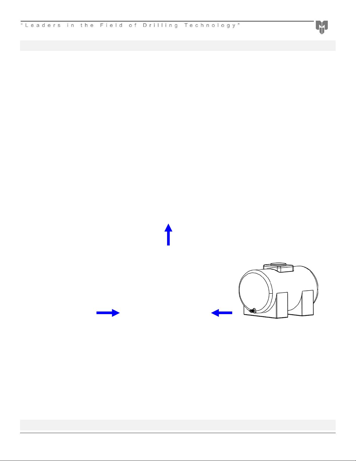
The basic setup is shown below.
Compressor
Minimum 275 PSI
The Installation and Operation section will deal with setup of the system and basic operation. Following that we will deal wi th
disassembly and servicing. When dealing with the HDD40 in the service section we will separate it into two parts: Firstly the Horizontal
Directional Drilling hammer component that makes drilling possible and secondly the Sonde housing component that makes steering
possible.
Horizontal Directional Drill
Including but not limited to:
Astec 3238, DD4045, DD 4
Ditch Witch 2720 M1, JT3020, JT4020 M1
Vermeer 24X40, 36X50, 50X100
Support Station
Rock Drill Oil Injection
Water injection
Compressor to Drill adapter
Water Tank
Dust Control
Sonde Cooling
2-4 Gal/Min
Mincon – “Leaders in Rock Drilling Technology” Page 3

2 Installation and Operation
2.1 Safety
Be sure to work safely at all times. Wear protective clothing and s afety equipment and observe all safety regulations as prescribed by
your employer, Government, or the site on which you work. Do not wear loose clothing that may get caught in rotating parts and cause
serious personal injury. Remem ber that a “Horizontal Down-the-Hole” percussive hammer emits noise and you should therefore take
every precaution to safeguard your hearing against damage by using proper ear protectors.
Use eye protection at all times. Rock chips and dust which may be discharged from the fac e of the bit or bore hole at high velocities
and can cause severe injury. Hammer s can be heavy – Always use proper and approved lifting equipment and take every precaution
to safeguard yourself against injury. Keep hands clear at all times – Beware of getting fingers trapped between the chuck and bit and
do not use hands or feet to clear the top of the borehole at any time. Other safety advice is given throughout this document which you
are advised to read.
2.2 Set up of HDD40 Hammer and Sonde
2.2.1 Storage
If you intend to store the HDD40 Hammer we recommend that ½ pint (¼ litre) of good quality rock drill oil be poured into the hammer to
protect it. To do this the hammer section should be unscrewed from the Bent Sub and then the oil should be poured into the top of the
hammer and let flow down into the piston chamber of the hammer to coat the parts and protect them from rust and corrosion. Once
completed the bent sub and the Sonde Housing can be reinstalled. Ensure that the thread protector and chuck cap are fitted to keep
debris out and to prevent oil leakage. Store the hammer horizontally in a clean dry place.
2.2.2 Setup of Sonde
When the HDD40 is supplied it will contain the necessary parts for the successful installation of a commercial Sonde. The two main
types of Sonde are dealt with in this manual: DCI Sonde and Sub Sight.
2.2.2.1 Installation of DCI Sonde
The following series of picture will detail the insta llat ion of a D CI Sonde into the HDD40. The same procedure should be used for
servicing or changing the Sonde at a later date.
STEP 1 STEP 2
Unscrew and remove Sonde Housing Backhead from the
Sonde Housing Sleeve
Insert and screw the Sonde Line Up Tool into the Sonde
Carriage retrieval cap and pull out the complete Sonde
Carriage assembly.
Mincon – “Leaders in Rock Drilling Technology” Page 4

Step 3 Step 4
Unscrew and remove the Sonde Carriage Locating Cap,
Springs and the DCI Adapter from the Sonde Carriage (At
Opposite end to the Sonde Carriage retrieval cap)
Step 5 Step 6
Loosen and remove with the Torque Wrench the DCI Adaptor
Locating cap from the tube. The correct end has locating
dimple.
Insert and push the DCI Sonde into the tube. Fit the DCI Adaptor Locating cap onto the DCI Sonde
ensuring the Locating cap’s intrical key is s eated correctly in
the Sonde Keyway.
Mincon – “Leaders in Rock Drilling Technology” Page 5

DCI Adaptor
Sonde Carriage
Groove
Step 7 Step 8 Step 9 Step 10
Push the Sonde in the rest of the way
and screw the DCI Adaptor Locating
Cap in and tighten snugly with the
Torque wrench.
Locating
Locating Cap
Dimple
Step 11 Step 12 Step 13
Insert first spring into the
Sonde Carriage.
Insert the DCI Adaptor into
the Sonde Carriage
Insert the second spring in to
the Sonde Carriage.
Align the Sonde Carriage Locating Cap
Groove with the DCI Adaptor Locking Dimple
and push the cap on so that the hex socket
of the Carriage Locating Cap fits over the
DCI Adaptor and then screw the Carriage
Locking Cap in place
Push the Sonde carriage into the Sonde
Housing Sleeve with the Sonde Carriage
Locating cap entering firs t.
Screw the Retrieval bar into the Sonde
Carriage and push forward until it stops.
Turn gently until you feel the Sonde
Carriage go forward and the Sonde
Carriage Locking Cap groove seats
over the Sonde Carriage Locating pin
(See Step 14 for details of the pin).
Mincon – “Leaders in Rock Drilling Technology” Page 6

Sonde Carriage
Locating Pin
Step 14 Step 15
Above picture shows the Sonde Carriage Locating Pin. The pin is in the
Bent Sub set so that the Sonde will be aligned correctly in the twelve
O’clock position.
Insert and screw the Sonde Housing Backhead in place.
Mincon – “Leaders in Rock Drilling Technology” Page 7
 Loading...