

Page 1

Tel: 763. 571.3121 • Fax: 763. 571.0927 • www.minco.com• Doc. #1116290(D)
TT211 and TT711
2-Wire Temperature Transmitter
Installation and Operating Instructions
TT211 / TT711
INTRINSICALLY SAFE
NON-INCENDIVE
Page 2

Minco Tel: 763. 571.3121 • Fax: 763. 571.0927 • www.minco.com • Doc. #1116290(D) 2
Description
Models TT211 and TT711 are 2-wire temperature transmitters for 2-lead 100 ohm or 1000
ohm platinum RTD's. These transmitters are FM-approved for use in Class I, Divisions 1 & 2,
Groups A, B, C, and D hazardous locations and appear in the approval guide as IS/I/1/ABCD
and NI/I/2/ABCD. The TemptranTM converts the RTD's (resistance temperature detector's)
signal into a current proportional to the RTD's temperature. The current changes according to
the range marked on the Temptran:
4 mA at the lowest temperature of the range, rising to 20 mA at the top of the range. The
leads that supply power also carry the current signal. Request Minco Application Aid 19 for
more information.
Installation
If installing the Temptran in a hazardous location, the installer must adhere to installation
requirements as set forth by the National Electrical Code (NEC) and any other applicable codes
and standards. See pages 3 - 7 for further information on installing these transmitters in a
hazardous location.
Locate the Temptran near the RTD, in an area where the ambient temperature stays between 25 and 85 °C (-13 and 185 °F). Mount with a #6 machine or #8 self-tapping screw.
Connect the Temptran as shown below, observing the +/- polarity of the current loop.
Maximum DC supply voltage = 35 VDC. The RTD connections have no polarity. For the RTD,
good connections are a must; a few ohms of resistance in the connection can cause an error of
several degrees.
The Temptran has been factory-calibrated for its marked temperature range or else for a
specific RTD. Do not change its zero and span adjustments.
DR: TPB CHK: MWG APP: _DKS
DATE: 05/04/93 05/05/93 05/05/93
Page 3

Minco Tel: 763. 571.3121 • Fax: 763. 571.0927 • www.minco.com • Doc. #1116290(D) 3
Wiring Diagram
R1
LINE
POWER
CONTROL ROOM
RESISTANCE
4-20 mA LOOP
COPPER LEADS,
TWISTED PAIR
CONTROLLER
AND/OR
INDICATOR
DC
SUPPLY
REMOTE SENSING SITE
THERMOMETER
TEMPTRAN
Installation of TT211 and TT711 Temptrans
TM
in Class I, Division 1 or 2, Groups A, B, C, and D
hazardous locations.
Read these instructions thoroughly before installing transmitters.
Per Factory Mutual,
1) Installation shall be in accord with these instructions and the National Electric Code.
2) If installing in a Class I, Division 1 hazardous area, then refer to document INST. 704,
"CONTROL DOCUMENT, SYSTEM APPROVALS FOR INTRINSICALLY SAFE
TRANSMITTERS" on pages 5-7 of this manual. The Simple Apparatus, referenced in
these pages, is the RTD temperature sensor or thermocouple.
3) If installing in a Class I, Division 2 hazardous area, then the transmitters must be
mounted in a vent-free enclosure, meeting the "Electrical Utilization Enclosure
Requirements" stated below with which only the Approved equipment will be installed.
All unused openings should be sealed.
4) Tampering and replacement with non-factory components may adversely affect the safe
use of the system.
Electrical Utilization Enclosure Requirements (Required for Division 2 areas only)
1. Each of the transmitters must be mounted within an enclosure to prevent personal injury
resulting from accessibility to live parts. This enclosure must comply with the requirements
listed below. Further details of the enclosure requirements may be found in ANSI/ISA
Standards S82.01, S82.02, and S82.03.
1.1 Accessibility - The transmitters must be installed within the enclosure so that its
circuits are accessible by the use of a tool only. A part is accessible when a) the IEC
Page 4

Minco Tel: 763. 571.3121 • Fax: 763. 571.0927 • www.minco.com • Doc. #1116290(D) 4
articulate accessibility probe applied in every possible position to the exterior or
exposed surfaces, including the bottom, or b) the IEC rigid accessibility probe applied
with a maximum force of 30 Newtons (6.75 lbs force) in every possible position to the
exterior or exposed surface, including the bottom, touches the part.
1.2 Protection from Fire - If the enclosure is non-metallic, it shall have the proper
flammability rating as detailed within ANSI/ISA Standard S82.01.
1.3 Grounding - A metallic enclosure must have a protective grounding terminal and
be marked as such. The size of the ground terminal is to be equivalent to the size of
the supply circuit conductor terminals. All accessible non-current conductive parts
must be bonded to the protective grounding terminal.
1.4 General Construction - The equipment enclosure, or parts of the enclosure,
required to be in place to comply with the requirements for protection from electric
shock, personal injury, protection from internal parts and wiring, and external cord
and cable assembly strain relief shall comply with the following tests for mechanical
strength:
a. Impact Tests - The equipment shall be held firmly against a rigid support and shall
be subjected to sets of three blows from a spring-operated impact hammer. The
hammer shall be applied to any external part that when broken is likely to expose live
parts. A window of an indicating device shall withstand an impact of 0.085 Newtonmeter (0.753-pound force-inch) from a hollow steel impact sphere 50.8 mm (2 inches)
in diameter and an approximate mass of 113.4 grams (4 ounces).
b. Pressure Tests - A force of 90 Newtons (20 pounds) shall be applied from a metal
rod 12.7 mm (.50 inch) in diameter, the end of which is rounded. The force shall be
applied for one minute to any point on the overall enclosure except the bottom. The
bottom shall sustain a force of 65 Newtons (15 pounds).
c. Tip Stability Test - Equipment having a weight of 11 kilograms (24 pounds) or
more shall not tip over when placed at the center of an inclined plane that makes an
angle of 10 degrees with the horizontal and then turned to the position (with all
doors, drawers and other openable and sliding parts in the least stable position) most
likely to cause tip-over.
Page 5

Minco Tel: 763. 571.3121 • Fax: 763. 571.0927 • www.minco.com • Doc. #1116290(D) 5
d. Sharp Edges - An accessible edge, projection, or corner of an enclosure, opening,
frame, guard, handle, or the like shall be smooth and well rounded, and shall not
cause a cut-type injury during normal use of the equipment.
REVISIONS
REV.
DESCRIPTION
DATE
ECO
APP.
A
ADDED NOTES 2-8, WAS INST 702(-), ADDED
“SIMPLE APPARATUS” NOTES
6/14/93
10344
MWG
C
Changed diagram on calibration, Modified
spacing
7/19/17
RAA
INST. 704(A)
Control Document, System Approvals for Intrinsically Safe Transmitters
The approved entity parameters specified are for Class I, Div.
1 Groups A, B, C, and D hazardous locations.
Models Models Models
TT210, TT211 TT176, TT216, TT676
TT710, TT711 TT190, TT230 TT220, TT221, TT720
Vmax = 35 volts Vmax = 35 volts Vmax = 35 volts
Imax = 150 Ma Imax = 150 mA Imax = 150 mA
Ci = 0 F Ci = 0 F Ci = 0 F
Li = 0 mH Li = 0 mH Li = 0 mH
1. The selected associated apparatus
and intrinsically safe apparatus must
meet the following conditions for
single channel operation:
Voc Vmax
Isc Imax
Ca Ci
La Li
2. The selected associated apparatus
and intrinsically safe apparatus must
meet the following conditions for dual
channel or multiple single channel
operation:
Vt Vmax
It Imax
Ca Ci
La Li
3. Voc, Vt, Isc, It, Ca and La are
parameters of the associated apparatus
where:
Voc,Vt = maximum open circuit
voltage
Isc,It = maximum short circuit
current
Ca = maximum allowable connected
capacitance
La = maximum allowable connected
inductance
Page 6

Minco Tel: 763. 571.3121 • Fax: 763. 571.0927 • www.minco.com • Doc. #1116290(D) 6
4. Vmax, Imax, Ci and Li are
parameters of the intrinsically safe
apparatus where:
Vmax = maximum safe input voltage
Imax = maximum safe input current
Ci = maximum unprotected internal
capacitance
Li = maximum unprotected internal
inductance
5. Installation must be in accordance
with the barrier manufacturers
instructions, ANSI/ISA RP12.6 and the
National Electrical Code (ANSI/NFPA
70).
6. Control room equipment connected to
the associated apparatus must not
contain a source of potential with
respect to earth in excess of 250 Vrms
or 250 Vdc.
7. Associated apparatus is not
required for operation in Division 2
hazardous (classified) locations.
8. For Division 2 installations, the
transmitters must be mounted within an
enclosure meeting the requirements of
ANSI/ISA S82.
Page 7

Minco Tel: 763. 571.3121 • Fax: 763. 571.0927 • www.minco.com 1116290(D) 7
ANY OF THE LISTED INTRINSIC SAFETY BARRIERS ARE FACTORY MUTUAL
APPROVED UNDER THE SYSTEM CONCEPT (SINGLE BARRIER ONLY) FOR USE
WITH ANY OF THE FOLLOWING MINCO TEMPTRANTM 4-20mA TRANSMITTER
MODELS:
TT176, TT190, TT210, TT211, TT216, TT220,
TT221, TT230, TT676, TT710, TT711, TT720
FOR USE IN CLASS I, DIVISION 1, GROUPS A, B, C, D HAZARDOUS
LOCATIONS.
BARRIER BARRIER
MANUFACTURER MODEL
MTL 702+
(MANASSAS, VA 706+
703-361-0111) 787S+
788+
2441
3041
3046B
4041
R. STAHL 9001/01-280-100-10
(WOBURN, MA 9001/51-280-091-14
800-782-4357) 9001/51-280-110-14
9002/13-280-110-00
PEPPERL & FUCHS KHD3-ICR/EX130 200
(TWINSBURG, OH KHD3-ICR/EX130 240
216-425-3555) KHP-103/EX-1A
KHP-104/EX-2A
KHP-105/EX-2A
KHZ-428/EX3
KHZ-487/EX3
KHZ-907/EX
Z130/EX
Z428/EX
Z479/EX
Z487/EX
MINCO PRODUCTS, INC.
INST. 704(A)
PAGE 2 OF 3
Page 8
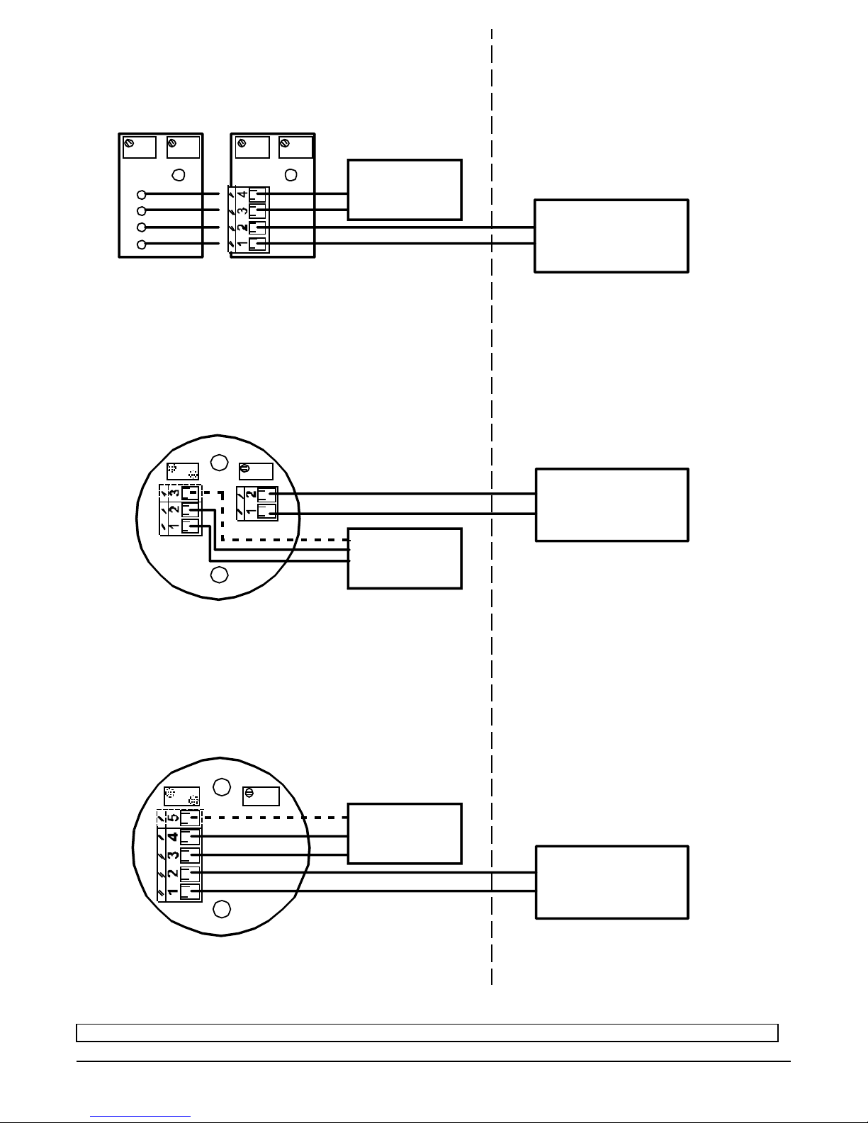
Minco Tel: 763. 571.3121 • Fax: 763. 571.0927 • www.minco.com • Doc. #1116290(D) 8
SIMPLE
APPARATUS
ASSOCIATED
APPARATUS
MODELS TT210, TT211,
TT710, OR TT711
BROWN
RED
BLACK
ORANGE
SIMPLE
APPARATUS
ASSOCIATED
APPARATUS
MODELS TT176, TT190, TT216,
TT230 OR TT676
SIMPLE
APPARATUS
ASSOCIATED
APPARATUS
MODELS TT220, TT221, OR TT720
NON-HAZARDOUS AREAHAZARDOUS AREA
CLASS I, DIVISION 1 OR 2,
GROUPS A, B, C, AND D
4
MINCO PRODUCTS, INC.
INST. 704(A)
PAGE 3 OF 3
Page 9

Minco Tel: 763. 571.3121 • Fax: 763. 571.0927 • www.minco.com • Doc. #1116290(D) 9
Calibration
1. Connect a power supply of 24 VDC and a digital milliammeter ( 5-1/2 digit preferred ) as
shown in the figure, or use a loop calibrator instead of the DC supply and milliammeter.
NOTE: Zero and Span resistance values are printed on the transmitter's label.
2. Connect a resistance decade box with a resolution of at least .01 ohms to the input of the
transmitter. If unsure or concerned about the decade box's accuracy, measure the zero and
span resistance setting, using a known-accurate ohmmeter and record decade box settings
before connecting decade box to the transmitter.
3. Set decade box resistance to simulate the 4 mA temperature.
4. Adjust ZERO potentiometer on the transmitter until the meter reads 4 mA.
5. Set decade box resistance to simulate the 20 mA temperature.
6. Adjust SPAN potentiometer on the transmitter until the meter reads 20 mA.
7. Repeat steps 3 - 7 until no further adjustment is necessary.
Page 10

Minco Tel: 763. 571.3121 • Fax: 763. 571.0927 • www.minco.com • Doc. #1116290(D) 10
Warranty
Items returned within one year from the date of sale, transportation prepaid, which Minco Products, Inc. (The
"Seller") reasonably determines to be faulty by reason of defective materials or faulty workmanship will be
replaced or repaired at the Seller's discretion, free of charge.
This remedy is to be the sole and exclusive remedy available to the buyer in the event of a breach by the Seller.
Items that show evidence of mishandling or misapplication may be returned by the Seller at the customer's
expense.
Furthermore, the Seller is not to be held responsible for consequential damages caused by its product except as
required under Minnesota Statutes, Section 336.1-719 (3).
This warranty is expressly in lieu of any other expressed warranty or implied warranty of merchantability or fitness
for a particular purpose, and of any other obligations or liability on the part of the Seller or its employees or
agents.
Specifications
Input:
100 or 1000 platinum 2-lead RTD.
Output:
4 to 20 mA DC over specified range.
Accuracy:
+/- 0.1% of span.
Linearity:
+/- 0.1% of span.
Adjustments:
Zero and Span, +/- 5% of span.
Ambient Temperature:
Operating: -25 to 85 °C ( -13 to 185 °F ).
Storage: -55 to 100 °C ( -67 to 212 °F ).
Ambient Temperature
Effects:
+/- 0.007% of span/°F (+/- 0.013% of span/°C).
+/- 0.014% of span/°F for spans less than 20 .
Warmup Drift:
+/- 0.1% of span max., assuming Vsupply = 24 VDC and Rloop = 250
ohms. Stable within 30 minutes.
Supply Voltage:
8.5 to 35 volts DC with no load. Reverse polarity protected.
Voltage effect:
+/- 0.001% of span per volt.
Maximum Load
Resistance:
The maximum allowable resistance of the signal-carrying loop is given
by this formula: Rloop max = (Vsupply-10)/.02 amps.
Maximum Output
Current:
27 mA.
Connections:
Terminal blocks for wires from AWG 22 to AWG 14.
Physical:
Epoxy potted for moisture resistance.
Weight:
1.1 oz. (30 grams).
Page 11

Minco Tel: 763. 571.3121 • Fax: 763. 571.0927 • www.minco.com • Doc. #1116290(D) 11
How to Order
TT211
Model Number:
TT211 = RTD Temptran
TT711 = Temptran Calibrated to a specific RTD
PD
Calibrated to match RTD Element Code:
PA = 100 ohm platinum (.00392)
PB = 100 ohm platinum (.00391)
PD = 100 ohm platinum (.00385, meets DIN 43760, Class B)
PE = 100 ohm platinum (.00385)
PF = 1000 ohm platinum (.00385)
PW = 1000 ohm platinum (.00375)
1
Output: 4 to 20 mA DC
C
Temperature Range: Use one of the over 175 range codes in the MINCO
Temptran sales bulletin. Note: A range that is available for a particular Temptran
model is not automatically available for the TT211/TT711; there may be a nominal
charge.
TT211PD1C Sample part number
Minco (Main Office) Customer Service/ Minco S.A.
7300 Commerce Lane Order Desk: Usine et Service
Minneapolis, MN Tel: 1.763.571.3123 Commercial, Z.I.
55432 Fax: 1.763.571.0942 09310 Aston, France
USA custserv@minco.com Tel: (33) 5 61 03 24 01
Tel: 1.763.571.3121 www.minco.com Fax: (33) 5 61 03 24 09 Stock # 360-00052(D) 103395
Fax: 1.763.571.0927
www.minco.com
 Loading...