

Page 1

2-WIRE PROGRAMMABLE TRANSMITTER TT519
Page 2

Minco Products, Inc. | Tel: 763.571.3121 • www.minco.com • 2612427 (B).......
1
2-WIRE PROGRAMMABLE TRANSMITTER TT519
CONTENTS
Application ......................................................................................................... 2
Technical characteristics ..................................................................................... 2
Mounting / Installation ....................................................................................... 2
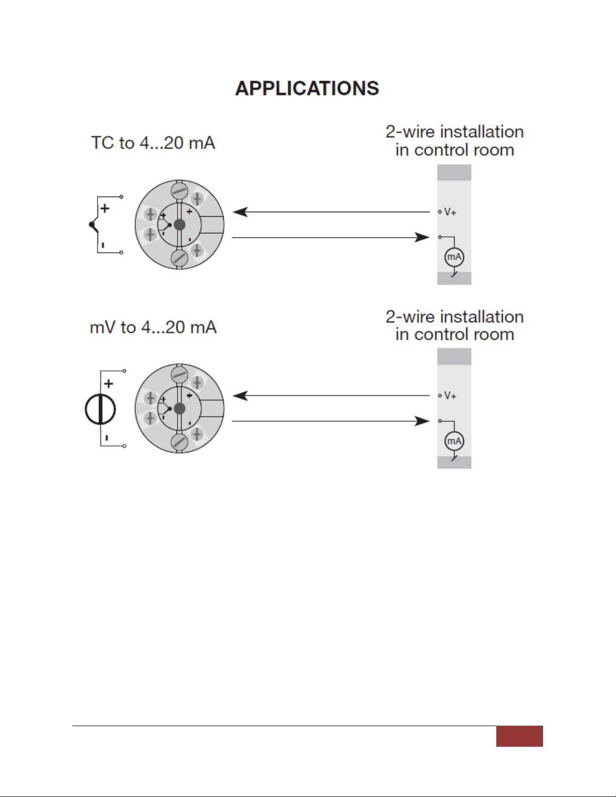
Applications ........................................................................................................ 3
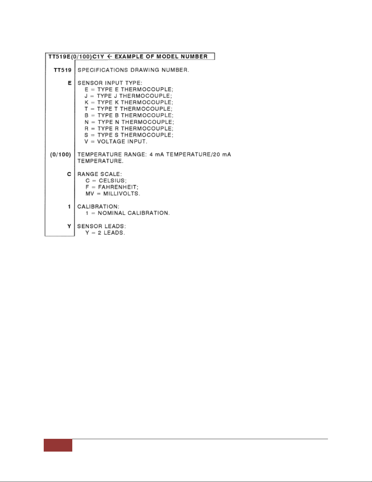
Order: TT519 ....................................................................................................... 4
Electrical specifications ....................................................................................... 4
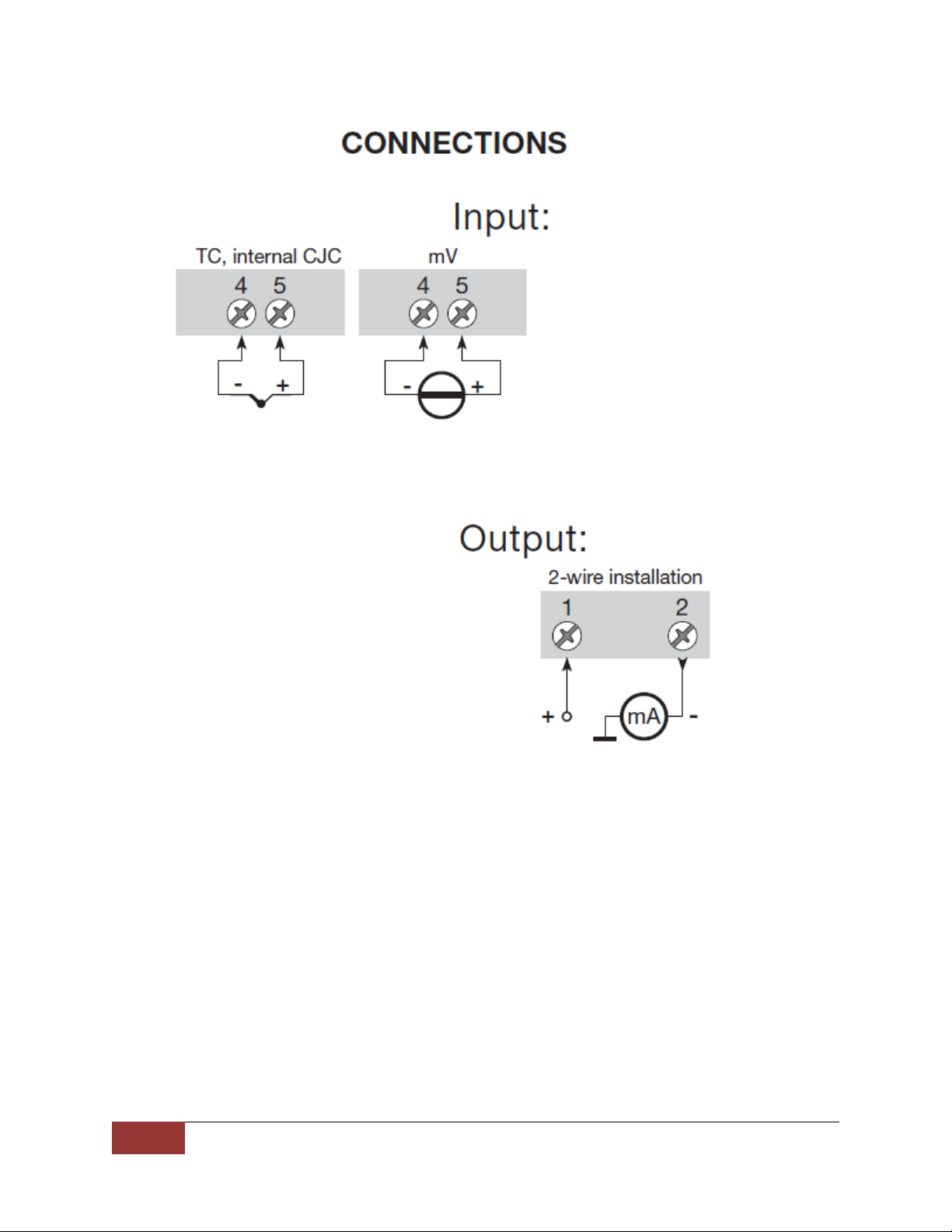
Connections ........................................................................................................ 8
Programming ...................................................................................................... 9
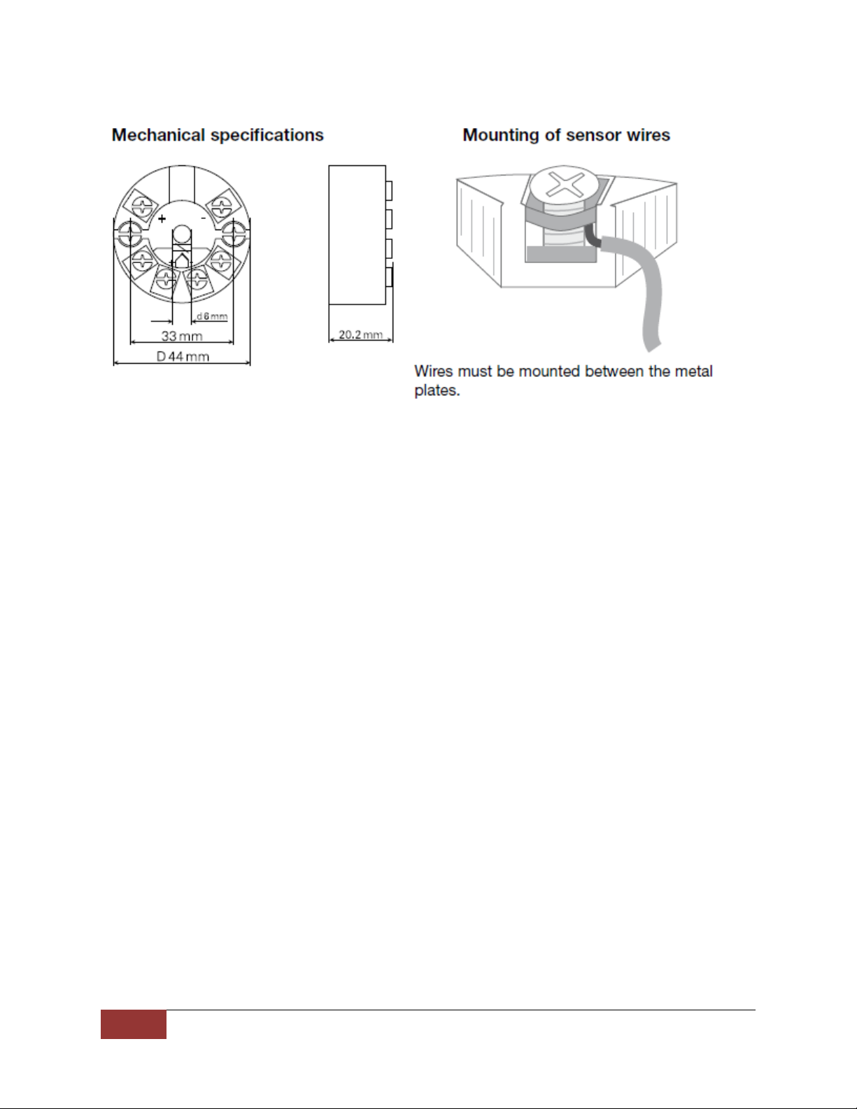
Mechanical specifications ................................................................................. 10
Mounting of sensor wires ................................................................................. 10
Appendix .......................................................................................................... 11
IECEx Installation Drawing .......................................................................... 11
ATEX Installation Drawing ........................................................................... 13
InNMETRO Instruções de Segurança ........................................................... 15
Page 3

2
Minco Products, Inc. | Tel: 763.571.3121 • www.minco.com • 2612427 (B).......
2-WIRE PROGRAMMABLE TRANSMITTER TT519
• TC input
• High measurement accuracy
• Galvanic isolation
• Programmable sensor error value
• For DIN form B sensor head mounting
Application
• Linearized temperature measurement with TC sensor.
• Amplification of bipolar mV signals to a 4…20 mA signal, optionally linearized according
to a defined linearization function.
Technical characteristics
• Within a few seconds the user can program the TT519 to measure temperatures within
all TC ranges defined by the norms.
• Cold junction compensation (CJC) with a built-in temperature sensor.
• Continuous check of vital stored data for safety reasons.
Mounting/installation
• For DIN form B sensor head mounting. In non-hazardous areas, the TT519 can be
mounted on a DIN rail with the AC807 Minco DIN rail adapter.
Page 4
Minco Products, Inc. | Tel: 763.571.3121 • www.minco.com • 2612427 (B).......
3
Page 5
4
Minco Products, Inc. | Tel: 763.571.3121 • www.minco.com • 2612427 (B).......
Order TT519:
Electrical specifications
Specifications Range:
-40°C to +85°C
Common specifications:
Supply voltage, DC ………………………………………………… 7.2…30 VDC
Internal consumption…………………………………………….. 25 mW…0.7 W
Voltage drop …………………………………………………………. 7.2 VDC
Isolation voltage, test/operation ………………………….. 1.5 kVAC/50VAC
Warm-up time ………………………………………………………. 5 min
Communications interface ……………………………………. Loop Link with AC205817
Signal /noise ratio …………………………………………………. Min. 60 dB
Response time (programmable) ……………………………. 1…60 s
EEprom error check ………………………………………………. < 3.5 s
Signal dynamics, input ………………………………………….. 18 bit
Signal dynamics, output ……………………………………….. 16 bit
Calibration temperature………………………………………… 20…28°C
Page 6

Minco Products, Inc. | Tel: 763.571.3121 • www.minco.com • 2612427 (B).......
5
Accuracy:
Calibration
Type
Accuracy
Temperature
Coefficient
Nominal
Type E, J, K, T, N
<±1°C
<±0.05°C/°C
Type B, R, S
<±2°C
<±0.2°C/°C
Voltage
<±10µV
<±1µV/°C
EMC immunity influence ………………………………………………………………………………… < ± 0.5% of span
Extended EMC immunity:
NAMUR NE 21, A criterion, burst ……………………………………………………………………. < ± 1% of span
Effect of supply voltage variation ……………………………. < 0.005% of span/VDC
Vibration ………………………………………………………………… IEC 60068-2-6:2007
2…25 Hz………………………………………………………±1.6 mm
25…100 Hz………………………………………………….±4 g
Max. wire size ……………………………............................... 1x1.5 mm2 stranded wire
Screw terminal torque …………………………………………….. 0.4 Nm
Humidity …………………………………………………………………. < 95% RH (non-cond.)
Dimensions ……………………………………………………………… ø 44 x 20.2 mm
Protection degree (enclosure / terminal) ………………… IP68 / IP00
Weight ……………………………………………………………………. 50 g
Page 7

6
Minco Products, Inc. | Tel: 763.571.3121 • www.minco.com • 2612427 (B).......
Electrical specification, input:
Max. offset ……………………………………………………………… 50% of selec. max. value
TC input:
Type
Min
temperature
Max
temperature
Min span
Standard
B
+400°C
+1820°C
100°C
IEC584
E
-100°C
+1000°C
50°C
IEC584
J
-100°C
+1200°C
50°C
IEC584
K
-180°C
+1372°C
50°C
IEC584
L
-100°C
+900°C
50°C
DIN 43710
N
-180°C
+1300°C
50°C
IEC584
R
-50°C
+1760°C
100°C
IEC584
S
-50°C
+1760°C
100°C
IEC584
T
-200°C
+400°C
50°C
IEC584
U
-200°C
+600°C
50°C
DIN 43710
W3
0°C
+2300°C
100°C
ASTM E988-90
W5
0°C
+2300°C
100°C
ASTM E988-90
LR
-200°C
+800°C
50°C
GOST 3044-84
Cold junction compensation ……………………………. < ±1.0°C
Sensor error detection …………………………………….. Yes
Sensor error current:
When detecting …………………………………. Nom. 33 µA
Else ……………………………………………………. 0 mA
Voltage input:
Measurement range ……………………………………….. -12…150mV
Min. span ………………………………………………………… 5 mV
Input resistance ………………………………………………. 10 MΩ
Output:
Current output:
Signal range ……………………………………………………. 4…20 mA
Min. signal range ……………………………………………. 16mA
Updating time ………………………………………………… 440 ms
Output signal at EEprom error ……………………….. ≤ 3.5 mA
Load resistance ………………………………………………. ≤ (Vsupply – 7.2)/0.023 [Ω]
Load stability ………………………………………………….. ±0.01% of span/100 Ω
Sensor error detection:
Programmable ……………………………………………….. 3.5…23 mA
Namur NE43 Upscale ……………………………………… 23 mA
Namur NE43 Downscale …………………………………. 3.5 mA
Of span = Of the presently selected range
Page 8

Minco Products, Inc. | Tel: 763.571.3121 • www.minco.com • 2612427 (B).......
7
Approvals
EMC ………………………………..……………..………….. 2014/30/EU
CCOE…………………………………………………………… P337392/1
RoHS .............................................................. 2011/65/EU
EAC................................................................. TR-CU 020/2011
Marine approval:
DNV-GL, Ships & Offshore.................................... Standard for Certification No. 2.4
Ex:
ATEX 2014/34/EU………………………………………. KEMA 06ATEX0062 X
IECEx………………………………………………………….. DEK 13.0035X
INMETRO………………………………………………….… DEKRA 16.0013 X
CCOE………………………………………………………….. P337392/2
EAC Ex TR-CU 012/2011……………………………… RU C-DK.GB08.V.00410
Page 9
8
Minco Products, Inc. | Tel: 763.571.3121 • www.minco.com • 2612427 (B).......
Page 10

Minco Products, Inc. | Tel: 763.571.3121 • www.minco.com • 2612427 (B).......
9
Programming
• Loop Link is a communication interface that is needed for programming the TT508,
TT509, TT510, TT511, TT518, TT519, TT520 & TT521.
• Use Minco AC205817.
• For programming please refer to the drawing below.
• Loop link is not approved for communication with modules installed in hazardous (Ex)
areas.
Page 11
10
Minco Products, Inc. | Tel: 763.571.3121 • www.minco.com • 2612427 (B).......
Page 12

Minco Products, Inc. | Tel: 763.571.3121 • www.minco.com • 2612427 (B).......
11
Appendix
IECEx Installation Drawing
For safe installation of the TT519 the following must be observed. The module shall only be
installed by qualified personnel who are familiar with the national and international laws,
directives and standards that apply to this area.
Year of manufacture can be taken from the first two digits in the serial number.
ATEX Certificate IECEx DEK 13.0035X
Marking
Ex ia IIC T4…T6 Ga
Ex ia IIIC Da
Ex ia I Ma
Standards EN 60079-0 : 2011, EN60079-11 : 2011, IEC 60079-26 : 2006
Page 13

12
Minco Products, Inc. | Tel: 763.571.3121 • www.minco.com • 2612427 (B).......
Installation Notes:
The sensor circuit is not infallibly galvanic isolated from the input circuit. However, the galvanic
isolation between the circuits is capable of withstanding a test voltage of 500Vac during 1
minute.
In a potentially explosive gas atmosphere, the transmitter shall be mounted in a metal form B
enclosure in order to provide a degree of protection of at least IP20 according to IEC60529. If
however the environment requires a higher degree of protection, this shall be taken into
account
If the transmitter is installed in an explosive atmosphere requiring the use of equipment
protection level Ga, Ma and Mb, and if the enclosure is made of aluminum, it must be installed
such, that ignition sources due to impact and friction sparks are excluded.
For installation in a potentially explosive dust atmosphere, the following instructions apply:
For explosive dust atmospheres, the surface temperature of the outer enclosure is 20 K above
the ambient temperature.
The transmitter shall be mounted in a metal enclosure form B according to DIN43729 that is
providing a degree of protection of at least IP6X according to IEC60529, that is suitable for the
application and correctly installed.
Cable entries and blanking elements shall be used that are suitable for the application and
correctly installed.
For an ambient temperature ≥ 60ºC, heat resistant cables shall be used with a rating of at least
20 K above the ambient temperature.
Page 14

Minco Products, Inc. | Tel: 763.571.3121 • www.minco.com • 2612427 (B).......
13
ATEX Installation Drawing
For safe installation of the TT519 the following must be observed. The module shall only be
installed by qualified personnel who are familiar with the national and international laws,
directives and standards that apply to this area.
Year of manufacture can be taken from the first two digits in the serial number.
ATEX Certificate KEMA 06ATEX 0062 X
Marking
II 1 G EX ia IIC T4…T6 Ga
II 1 D Ex ia IIIC Da
II M1 Ex ia I Ma
Standards EN 60079-0 : 2012, EN60079-11 : 2012, EN 60079-26 : 2007,
EN 60079-15 : 2010
Page 15

14
Minco Products, Inc. | Tel: 763.571.3121 • www.minco.com • 2612427 (B).......
Installation notes:
The sensor circuit is not infallibly galvanic isolated form the input circuit. However, the galvanic
isolation between the circuits is capable of withstanding a test voltage of 500Vac during 1
minute.
In a potentially explosive gas atmosphere, the transmitter shall be mounted in an enclosure in
order to provide a degree of protection of at least IP20 according to EN60529.
If the transmitter is installed in an explosive atmosphere requiring the use of equipment of
category 1 G, 1 M, or 2 M, and if the enclosure is made of aluminum, it must be installed such,
that even in the event of rare incidents, ignition sources due to impact and friction, sparks are
exclude: if the enclosure is made of non-metallic materials, electrostatic charging shall be
avoided.
For installation in a potentially explosive dust atmosphere, the following instructions apply:
The transmitter shall be mounted in a metal enclosure form B according to DIN43729 that is
providing a degree of protection of at least IP6X according to EN60529, that is suitable for the
application and correctly installed.
Cable entries and blanking elements shall be used that are suitable for the application and
correctly installed.
For an ambient temperature ≥ 60°c, heat resistance cable shall be used with a rating of at least
20 K above the ambient temperature
The surface temperature of the enclosure is equal to the ambient temperature plus 20 K, for a
dust layer with a thickness up to 5 mm.
Page 16
Minco Products, Inc. | Tel: 763.571.3121 • www.minco.com • 2612427 (B).......
15
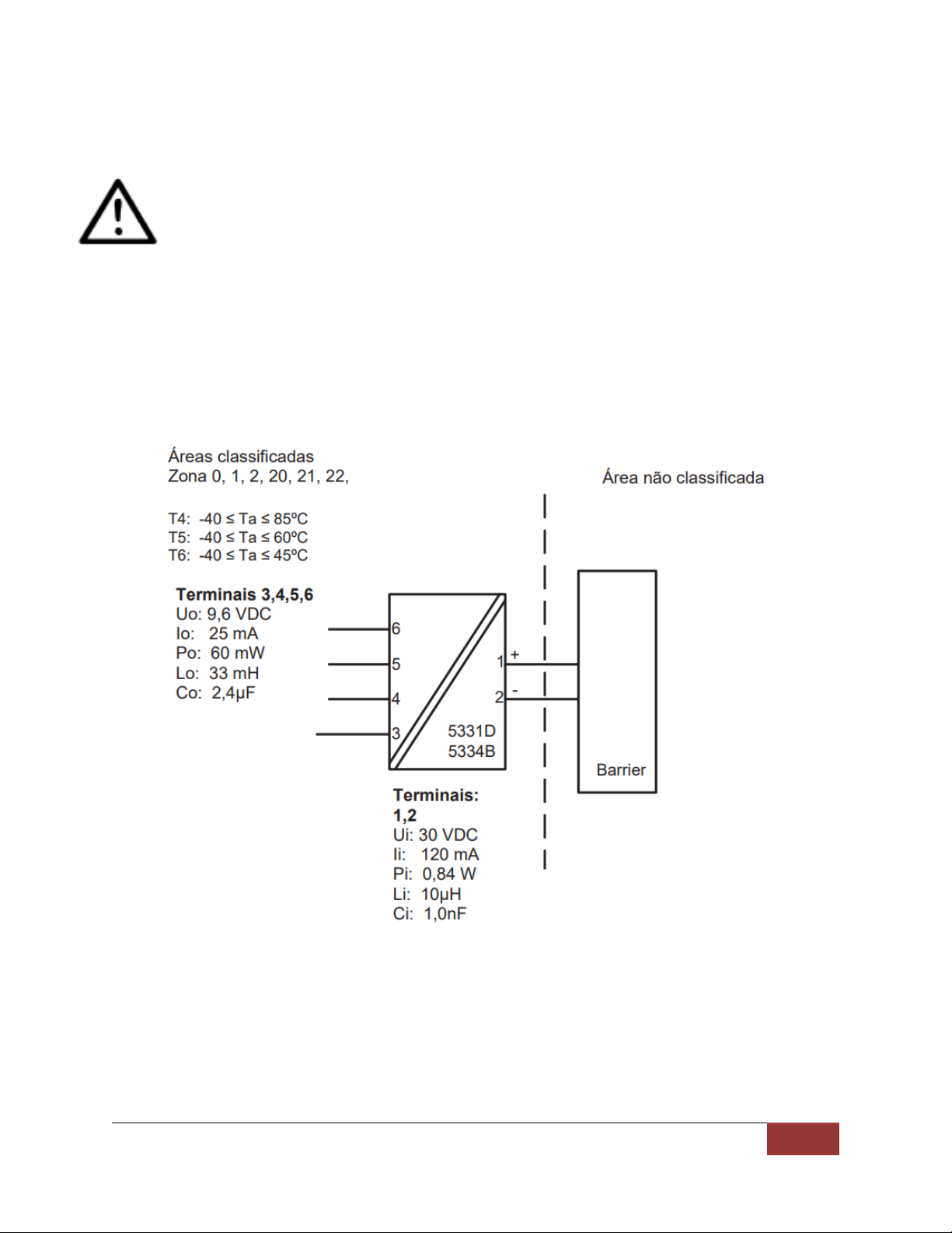
Desenho de Instalação InNMETRO
Para instalação segura do TT519 o seguinte deve ser observado. O modo deve apenas ser
instalado por pessoas qualificadas que são familiarizadas com as leis nacionais e internacionais,
diretrizes e padrões que se aplicam a esta área.
Ano de fabricação pode ser pego dos dois primeiros dígitos do número de série.
Certificado DEKRA 16.0013 X
Marcas Ex ia IIC T6…T4 Ga
Ex ia IIIC Da
Normas ABNT NBR IEC 60079-0 : 2013; ABNT NBR IEC 60079-11 : 2013
Page 17

16
Minco Products, Inc. | Tel: 763.571.3121 • www.minco.com • 2612427 (B).......
Notas para instalação
O circuito do sensor não é isolado galvanicamente infalível do circuito de entrada. Contudo, a
isolação galvânica entre os circuitos é capaz de resistir a um teste de tensão de 500Vac
durante 1 minuto.
Em uma atmosfera de gás potencialmente explosiva, o transmissor deve ser montado em um
enclousure a fim de garantir um grau de proteção de no mínimo IP20 de acordo com
EN60529. Se contudo o ambiente requer um nível de proteção maior, isso deve ser levado em
conta
Se o transmissor é instalado em uma atmosfera explosiva exigindo o uso de equipamento de
categoria Ga e se o enclosure é feito de alumínio, ele deve ser instalado de modo que, mesmo
em caso de avaria rara, fontes de ignição devido a impacto e fricção, faíscas são eliminadas; se
o enclosure é feito de materiais não metálicos, cargas eletroestáticas devem ser evitadas.
Para instalação em atmosfera de poeira potencialmente explosiva, as instruções a seguir:
O transmissor deve ser montado em enclosure de metal forma B de acordo com DIN43729
que está fornecendo um grau de proteção de pelo menos IP6X de acordo com EN60529. Isso é
adequado para aplicação e corretamente instalado.
As entradas dos cabos e os elementos de obturação que podem ser utilizados são adequados
para a aplicação e corretamente instalados.
Para temperatura ambiente >= 60ºC, fios de resistência ao calor devem ser usados com uma
faixa de pelo menos 20K acima da temperatura ambiente.
A temperatura da superfície do enclosure é igual à temperatura ambiente mais de 20 K, por
uma camada de pó, com uma espessura até 5 mm.
 Loading...