

Page 1
MINCO
TT190
TT190 and TT230
2-wire Temperature Transmitters
Installation and Operating Instructions
INTRINSICALLY SAFE
NON-INCENDIVE
MINCOMINCO PRODUCTS, INC.
TT230
7300 Commerce Lane, Minneapolis, Minnesota 55432-3177 U.S.A.
Telephone: (763)571-3121 FAX: (763)571-0927
1
Page 2
Description
Models TT190 and TT230 are 2-wire temperature transmitters for T/C (thermocouple thermometers).
These transmitters are FM-approved for use in Class I, Divisions 1 or 2, Groups A, B, C, and D
hazardous locations and appear in the approval guide as IS/I/1/ABCD and NI/I/2/ABCD. The
TemptranTM converts the T/C's signal into a 4 to 20 mA current. The current changes according to
the range marked on the Temptran: 4 mA at the lowest temperature of the range, rising to 20 mA at
the top of the range. The leads that supply power also carry the current signal.
Installation
If installing the Temptran in a hazardous location, the installer must adhere to installation
requirements as set forth by the National Electrical Code (NEC) and any other applicable codes and
standards. See pages 3-7 for further information on installing these transmitters in a hazardous
location.
Locate the Temptran near the T/C, in an area where the ambient temperature stays between -40 and
85 C (-40 and 185 F). Mount with #8 machine screws using the two mounting holes provided in
the transmitter case.
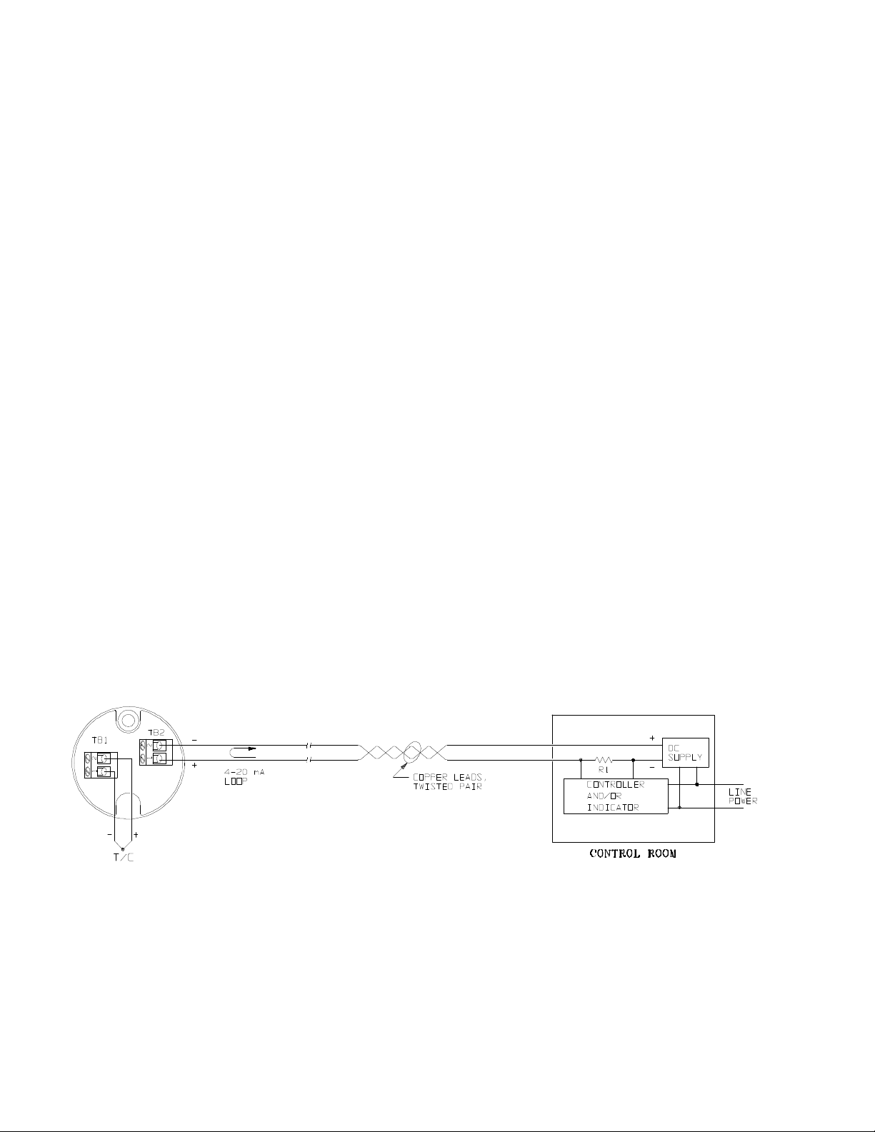
Connect the Temptran as shown below, observing the +/- polarity of the current loop and T/C
connections. Maximum DC supply voltage = 35 VDC. The T/C connections for the Temptran in the
wiring diagram below must be connected as shown or the transmitter will not function properly.
For model TT190, the Temptran has been factory-calibrated for its marked temperature range. Do
not change its zero and span adjustments.
Wiring Diagram
2
Page 3

Installation of TT190 and TT230 TemptransTM in Class I, Divisions 1 or 2, Groups A, B, C, and D
hazardous locations.
Read these instructions thoroughly before installing transmitters.
Per Factory Mutual,
1) Installation shall be in accord with these instructions and the National Electric Code.
2) If installing in a Class I, Division 1 hazardous area, then refer to dwg. INST. 704, "CONTROL
DOCUMENT, SYSTEM APPROVALS FOR INTRINSICALLY SAFE TRANSMITTERS" on pages
5-7 of this manual.
3) If installing in a Class I, Division 2 hazardous area, the transmitters must be mounted in a ventfree enclosure, meeting the "Electrical Utilization Enclosure Requirements" stated below with
which only the Approved equipment will be installed. All unused openings should be sealed.
4) Tampering and replacement with non-factory components may adversely affect the safe use of
the system.
Electrical Utilization Enclosure Requirements (Required for Division 2 areas only)
1. Each of the transmitters must be mounted within an enclosure to prevent personal injury resulting
from accessibility to live parts. This enclosure must comply with the requirements listed below.
Further details of the enclosure requirements may be found in ANSI/ISA Standards S82.01, S82.02,
and S82.03.
1.1 Accessibility - The transmitters must be installed within the enclosure so that its circuits are
accessible by the use of a tool only. A part is accessible when a) the IEC articulate accessibility
probe applied in every possible position to the exterior or exposed surfaces, including the bottom,
or b) the IEC rigid accessibility probe applied with a maximum force of 30 newtons (6.75 lbs
force) in every possible position to the exterior or exposed surface, including the bottom, touches
the part.
1.2 Protection From Fire - If the enclosure is non-metallic, it shall have the proper flammability
rating as detailed within ANSI/ISA Standard S82.01.
1.3 Grounding - A metallic enclosure must have a protective grounding terminal and be marked
as such. The size of the ground terminal is to be equivalent to the size of the supply circuit
conductor terminals. All accessible non-current conductive parts must be bonded to the
protective grounding terminal.
1.4 General Construction - The equipment enclosure, or parts of the enclosure, required to be in
place to comply with the requirements for protection from electric shock, personal injury,
protection from internal parts and wiring, and external cord and cable assembly strain relief shall
comply with the following tests for mechanical strength:
3
Page 4

a. Impact Tests - The equipment shall be held firmly against a rigid support and shall be
subjected to sets of three blows from a spring-operated impact hammer. The hammer
shall be applied to any external part that when broken is likely to expose live parts. A
window of an indicating device shall withstand an impact of 0.085 Newton-meter (0.753
pound force-inch) from a hollow steel impact sphere 50.8 mm (2 inches) in diameter and
an approximate mass of 113.4 grams (4 ounces).
b. Pressure Tests - A force of 90 Newtons (20 pounds) shall be applied from a metal rod
12.7 mm (.50 inch) in diameter, the end of which is rounded. The force shall be applied
for one minute to any point on the overall enclosure except the bottom. The bottom shall
sustain a force of 65 Newtons (15 pounds).
c. Tip Stability Test - Equipment having a weight of 11 kilograms (24 pounds) or more shall
not tip over when placed at the center of an inclined plane that makes an angle of 10
degrees with the horizontal and then turned to the position (with all doors, drawers and
other openable and sliding parts in the least stable position) most likely to cause tip-over.
d. Sharp Edges - An accessible edge, projection, or corner of an enclosure, opening, frame,
guard, handle, or the like shall be smooth and well rounded, and shall not cause a cuttype injury during normal use of the equipment.
4
Page 5

567
Page 6

Page 7

Page 8

Calibration
NOTE: Steps 1 - 3 are only required if calibrating model TT230. If calibrating model TT190, then skip
to step 4.
1. Desired Zero (4 mA) temperature must be within the limits specified in table below.
2. Select desired span from the table. Temperature Span equals the desired temperature at 20 mA
minus the desired temperature at 4 mA. For example, suppose you have an RC range Temptran,
and you want to calibrate to a range of -50 to 200 C, then the span = 200 - (-50) = 250 C.
Temperature Span
T/C Type: K E, J, K, T K
Connect: RB range RC range RE range
1 - A 50 to 70 °C 150 to 200 °C 300 to 400 °C
2 - A 70 to 100 °C 200 to 300 °C 400 to 600 °C
3 - A 100 to 200 °C 300 to 600 °C 600 to 1200 °C
Zero (4 mA): -50 to 50 °C -100 to 200 °C -100 to 500 °C
3. Bend over the lead designated 1, 2, or 3, depending on selection from table, to the A lead and
solder. See Figure 1 below. For the above example, lead 2 should be soldered to lead A.
4. Connect a power supply of 24 VDC, and a digital milliammeter (5-1/2 digit preferred) as shown in
figure 1, or use a loop calibrator instead of the DC supply and milliammeter.
Figure 1
Figure 1
8
Page 9

NOTE: For model TT190, the Zero and Span millivolt values are printed on the transmitter's label.
For model TT230, refer to a mV vs. T chart for the desired element type.
5. Connect a thermocouple simulator with cold junction compensation to the input of the transmitter.
6. Set thermocouple simulator to simulate the 4 mA temperature. For the given example, the
simulator should be set to -50 C.
7. Adjust ZERO potentiometer on the transmitter until the meter reads 4 mA.
8. Set thermocouple simulator to simulate the 20 mA temperature. For the given example, the
simulator should be set to 200 C.
9. Adjust SPAN potentiometer on the transmitter until the meter reads 20 mA.
10. For model TT230, repeat steps 6 - 9 until no further adjustment is necessary. Model TT190 has
non-interacting Zero and Span adjustments; therefore, steps 5 - 8 should not have to be
repeated. However, it is recommended that step 5 be repeated to check that meter still reads 4
mA to ensure proper calibration.
Warranty
Items returned within one year from the date of sale, transportation prepaid, which Minco Products,
Inc. (The "Seller") reasonably determines to be faulty by reason of defective materials or faulty
workmanship will be replaced or repaired at the Seller's discretion, free of charge.
This remedy is to be the sole and exclusive remedy available to the buyer in the event of a breach by
the Seller. Items that show evidence of mishandling or misapplication may be returned by the Seller
at the customer's expense.
Furthermore, the Seller is not to be held responsible for consequential damages caused by its
product except as required under Minnesota Statutes, Section 336.1-719 (3).
This warranty is expressly in lieu of any other expressed warranty or implied warranty of
merchantability or fitness for a particular purpose, and of any other obligations or liability on the part
of the Seller or its employees or agents.
9
Page 10

Specifications
Input: Type E, J, K, or T thermocouples.
Output: 4 to 20 mA DC over specified range.
Accuracy:
TT190: +/- 0.2% of span.
TT230: +/- 0.3% of span when factory calibrated.
Linearity: Voltage linear.
Ambient Temperature:
Operating: -40 to 85°C (-40 to 185°F ).
Storage: -55 to 100°C (-67 to 212°F ).
Ambient Temperature Effects:
TT190: +/- 0.018% of span°C.
TT230: +/- 0.025% of span°C.
Cold Junction Compensation:
+/- 0.03°C/°C for -25 to 70°C ambients.
+/- 0.06°C/°C for -40 to -25 and 70 to 85°C ambients.
Model Number Coding:
TT190 JU 1 K . . . Sample part number
Temperature Range: Use one of the over 175 range codes in the MINCO Temptran sales
bulletin. Note: A range that is available for a particular Temptran model is not automatically
available for the TT190 or TT230; there may be a nominal charge. Also, ranges available for the
TT190 and TT230 depend on T/C type.
Output: 1 = 4 to 20 mA DC.
Calibrated to match T/C Type:
EU = Type E ( Chromel - Constantan ), Ungrounded Junction
JU = Type J ( Iron - Constantan ), Ungrounded Junction
KU = Type K ( Chromel - Alumel ), Ungrounded Junction
TU = Type T ( Copper - Constantan ), Ungrounded Junction
Adjustments:
TT190: Zero and Span, +/- 5% of span.
TT230: Depends on temperature range selected.
Warmup Drift: +/- 0.2% of span max., assuming Vsupply = 24
VDC and Rloop = 250 ohms. Stable within 30 minutes.
Supply Voltage: 10 to 35 volts DC with no load.
Reverse polarity protected.
Voltage effect: +/- 0.001% of span per volt.
Maximum Load Resistance: The maximum allowable
resistance of the signal-carrying loop is given by this
formula: Rloop max = (Vsupply-10)/.02 amps.
Maximum Output Current: 27 mA.
Connections: Terminal blocks for wires from AWG 22 to
AWG 14.
Physical: Epoxy potted for moisture resistance.
Weight: 1.8 oz. (58 grams).
Model Number: TT190 T/C Temptran
TT230 Rangeable T/C Temptran
When quality and performance are as important as price, call...
MINCOMINCO PRODUCTS, INC.
7300 Commerce Lane/Minneapolis, Minnesota 55432-3177 U.S.A.
Telephone:(763)571-3121 FAX:(763)571-0927
©2001 MINCO PRODUCTS, INC.
10
 Loading...