

Page 1

Tel: 763. 571.3121 • Fax: 763. 571.0927 • www.minco.com
TT115/TT155/TT165/TT297 TemptranTM
2-wire Temperature Transmitter for RTD Thermometers
Installation and Operating Instructions
Page 2

Minco Tel: 763. 571.3121 • Fax: 763. 571.0927 • www.minco.com 2
Description
Designed for use in room air applications, model TT115/TT155/TT165 is a 2-wire temperature
transmitter for RTD (Resistance Temperature Detector) thermometers. The TemptranTM
converts the RTD's signal into a 4 to 20 mA DC current. The current changes according to the
range in which the Temptran is calibrated: 4 mA at the lowest temperature of the range, rising
to 20 mA at the top of the range. The leads that supply power also carry the current signal.
Note: Transmitter circuit board only, Room Air housing and RTD sold separately.
Specifications
Sensing Element:
100 ohm platinum RTD, 0.00392 ohm/ohm/°C TCR,
100 ohm platinum RTD, 0.00391 ohm/ohm/°C TCR,
100 ohm platinum RTD, 0.00385 ohm/ohm/°C TCR,
1000 ohm platinum RTD, 0.00385 ohm/ohm/°C TCR
1000 ohm platinum RTD, 0.00375 ohm/ohm/°C TCR
Output:
4 to 20 mA DC over specified range, limited to 30mA maximum.
Calibration Accuracy:
± 0.1% of Span
Transmitter Linearity:
± 0.1% of Span.
Physical:
Printed circuit board designed to mount inside the S470 series
thermostat housing with RTD
Operating Environment:
32° to 122°F (0° to 50°C), non-condensing.
Storage Environment:
-67° to 212°F (-55° to 100°C), non-condensing.
Ambient Temperature
Effects:
± 0.007% Span/°F (± 0.014% Span/°F for Spans < 100°F)
Warm-up Drift:
± 0.1% of Span max., assuming Vsupply = 24 VDC and Rloop =
250 ohms. Stable within 30 minutes.
Supply Voltage:
8.5 to 35 volts DC, non-polarized.
Input Voltage Effect:
± 0.001% of span per volt from 8.5 to 35 VDC.
Maximum Load
Resistance:
The maximum allowable resistance of the signal-carrying loop,
including extension wires and load resistance, is given by this
formula: Rloop max = (Vsupply-8.5)/.02 amps. For example, if
the supply voltage is 24 VDC, the loop resistance must be less
than
775 .
System Integration:
Output “High” (22-28mA) with sensor open. Output “Low”
(3.3-3.7mA) with sensor shorted.
Zero and Span
Adjustment:
Non-interacting, Zero and Span ±5%.
Maximum Output
Current:
30 mA.
Power Connections:
Screw terminals, non-polar (connect either way).
Sensor Connections:
Screw terminals, non-polar (connect either way).
Page 3
Minco Tel: 763. 571.3121 • Fax: 763. 571.0927 • www.minco.com 3
Installation
Locate the Temptran near the RTD, in an area where the ambient temperature stays between
the temperature range of the output.
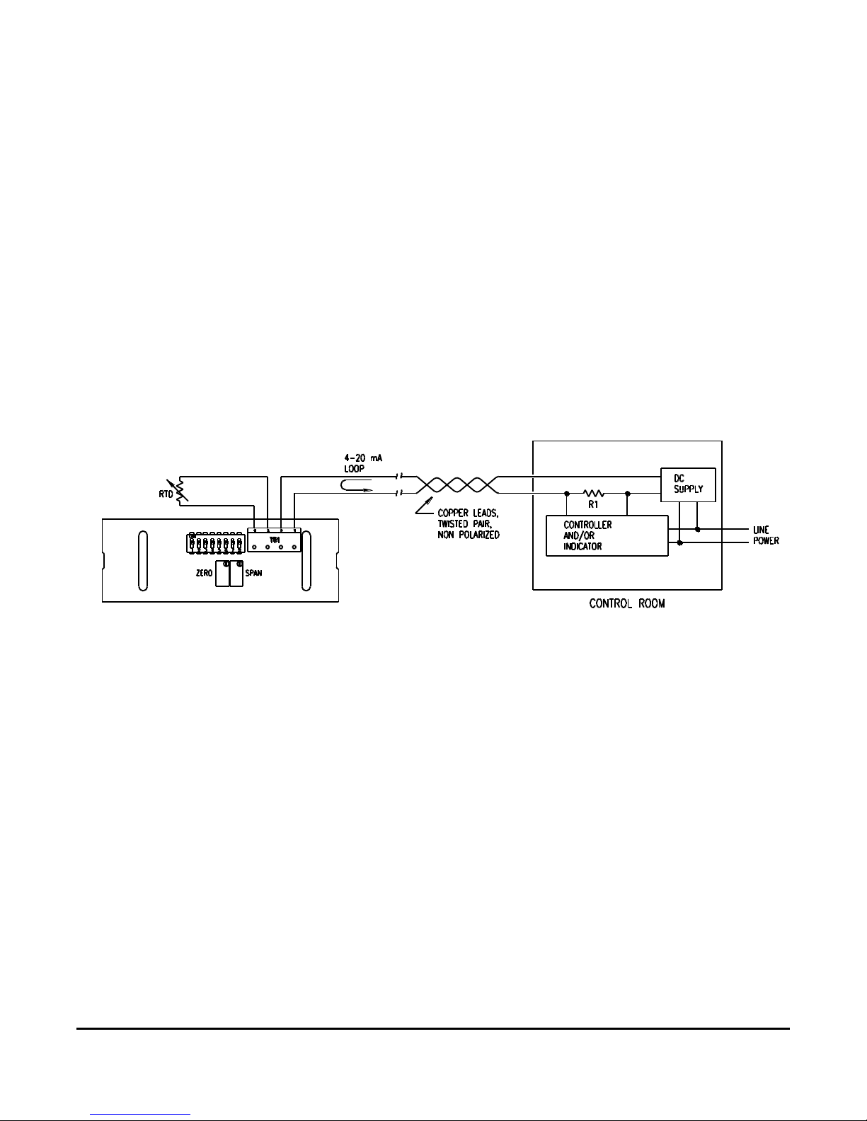
Connect the Temptran as shown in the wiring diagram below. The transmitter’s power and RTD
connections are designed for non-polar hook-up, so polarity is not important. The maximum
DC supply should not exceed 35 VDC. For the RTD, good connections are a must, a few ohms
of resistance in the connection could cause an error of several degrees.
The Temptran has been factory-calibrated to its marked temperature range or to a specific
RTD, do not change its Zero or Span adjustments.
Wiring Diagram
Figure 1
Power Supply
DC power supply requirements are determined by the transmitter’s minimum voltage
requirement and voltage drop across the load resistor and installation lead wires.
Example: The transmitter requires 8.5 Volts minimum. A typical 250 ohm load resistor drops 5.0
Volts @ 20 mA. Allowing a margin of 0.5 Volts for the supply permits 25 ohms of lead wire
resistance for remote installation. Totaling these, we get a minimum power supply requirement
of 14 VDC.
Using a 24 VDC power supply will take care of nearly all installations, but the transmitter will
operate at voltages up to 35 VDC.
Page 4
Minco Tel: 763. 571.3121 • Fax: 763. 571.0927 • www.minco.com 4
Calibration Procedure
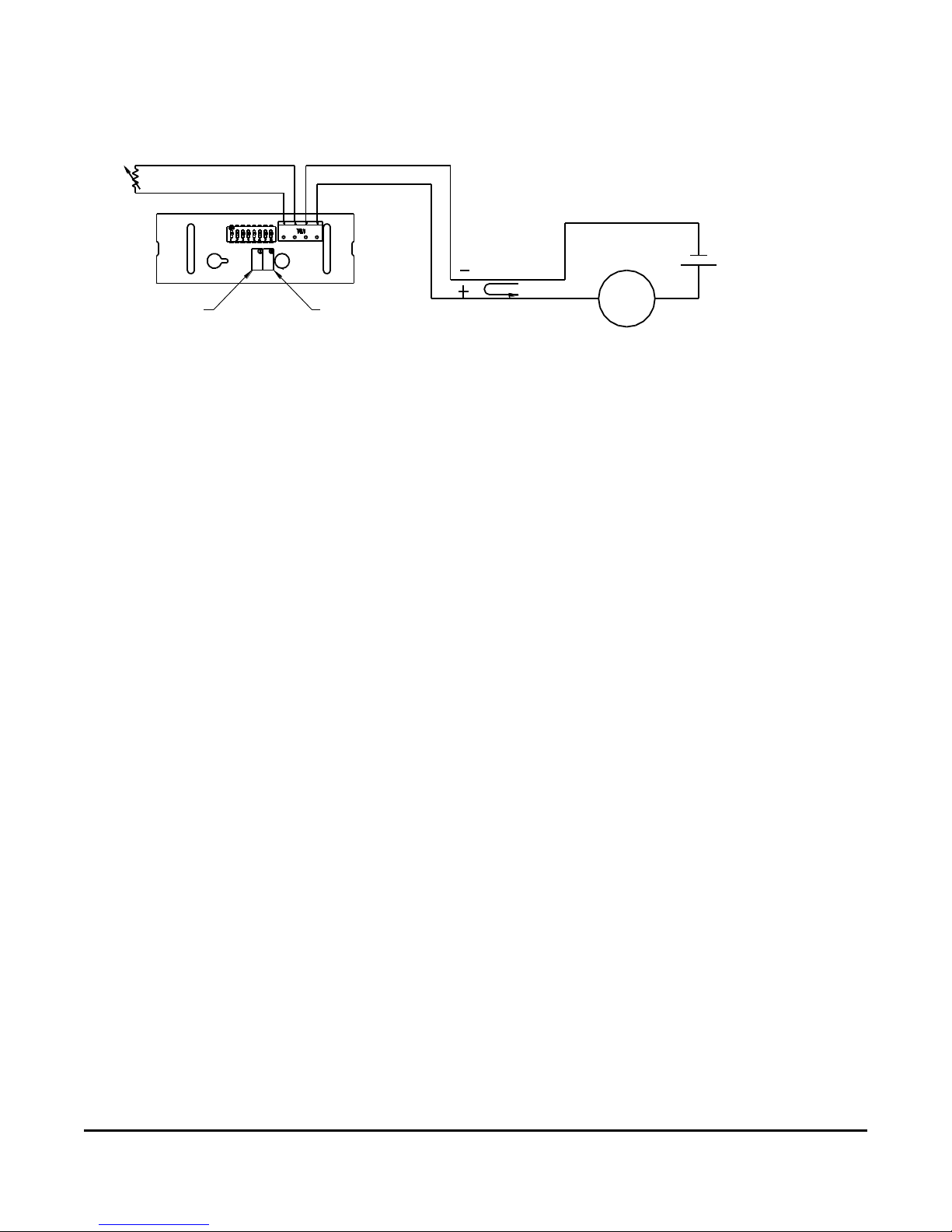
1. Connect the equipment as shown below (Figure 2) substituting a resistance decade box,
with resolution of at least 0.01 ohm, in place of the RTD.
DECADE
BOX
SPAN ADJ.
ZERO ADJ.
4-20 mA
LOOP
mA
INDICATOR
24 VDC
POWER SUPPLY
Figure 2
2. Determine sensor resistance corresponding to the lower and upper temperature range of
the transmitter from Tables 3 and 4 (page 6). Using “RTD Calc” a more complete resistance
vs. temperature chart can be printed; Download it from Minco’s web site, www.minco.com.
3. Set the decade box to the resistance value corresponding to the lower temperature. Adjust
the Zero pot until the milliammeter reads 4.0 mA +/- 0.016 mA.
4. Set the decade box to the resistance value corresponding to the upper temperature. Adjust
the Span pot until the milliammeter reads 20.0 mA +/- 0.016 mA.
5. Set the decade box to the resistance value corresponding to the lower temperature and
verify that the milliammeter still reads 4.0 mA +/- 0.016 mA. Correct if necessary, then
repeat steps 4 and 5.
Transmitter Ranging
The transmitter is initially calibrated to a specific temperature range, as shown on the label
attached to the housing. Unless a different range is desired, ranging is not necessary. If the
temperature range is changed, recalibrate the transmitter as described in the section,
Calibration Procedure.
When a different temperature range is desired, Tables 1, 2, 3, and 4 (Pages 5 and 6) provide
range switch settings corresponding to the various temperature ranges. Switches 1 to 4 set the
lower temperature limit (Zero) of the transmitter. Switches 5 to 8 set the upper minus lower
temperature (Span) of the transmitter.
For example, a temperature range of 30 to 90°F has a Zero of 30°F and a Span of 60°F (90-30).
Table 1 shows the closest Zero range is 30°F with switches 1 through 4, respectively, in the OFF,
ON, ON, and OFF positions. Likewise, Table 2 shows the closest Span range is 58°F with
switches 5 through 8, respectively, in the ON, ON, OFF, and ON positions. Once the switches
are set, the Zero and Span trim pots should provide sufficient adjustments to calibrate the
transmitter.
Page 5

Minco Tel: 763. 571.3121 • Fax: 763. 571.0927 • www.minco.com 5
In the event that the trim pots do not have sufficient adjustments, the switch settings should
then be changed. In the above example, if the Zero trim pot cannot adjust the transmitter
current down to 4mA with the 30°F Zero switch settings, then the Zero switch settings should
then be changed to 39°F (OFF, ON, OFF and ON) which is the next higher range. Likewise if the
Span trim pot does not have sufficient adjustment, then the Span switch settings should be
changed.
Page 6

Minco Tel: 763. 571.3121 • Fax: 763. 571.0927 • www.minco.com 6
Zero Switch Settings for 100 Ohm PT Elements
Table 1
Span Switch Settings for 100 Ohm PT Elements
(Upper Minus Lower Temperature Limits)
Table 2
* Span = Upper - Lower Temperature. Zero ranges overlap next adjacent range.
Switch Settings
Center Point
1 2 3 4 °F
°C
ON
ON
ON
ON
-71
-57
ON
ON
ON
OFF
-62
-52
ON
ON
OFF
ON
-53
-47
ON
ON
OFF
OFF
-44
-42
ON
OFF
ON
ON
-33
-36
ON
OFF
ON
OFF
-24
-31
ON
OFF
OFF
ON
-15
-26
ON
OFF
OFF
OFF
-6
-21
OFF
ON
ON
ON 3 -16
OFF
ON
ON
OFF
14
-10
OFF
ON
OFF
ON
23
-5
OFF
ON
OFF
OFF
32
0
OFF
OFF
ON
ON
41
5
OFF
OFF
ON
OFF
52
11
OFF
OFF
OFF
ON
61
16
OFF
OFF
OFF
OFF
73
23
Switch Settings
Center Point
5 6 7 8 °F
°C
ON
ON
ON
ON
43
24
ON
ON
ON
OFF
52
29
ON
ON
OFF
ON
63
35
ON
ON
OFF
OFF
74
41
ON
OFF
ON
ON
85
47
ON
OFF
ON
OFF
94
52
ON
OFF
OFF
ON
103
57
ON
OFF
OFF
OFF
113
63
OFF
ON
ON
ON
124
69
OFF
ON
ON
OFF
135
75
OFF
ON
OFF
ON
144
80
OFF
ON
OFF
OFF
153
85
OFF
OFF
ON
ON
164
91
OFF
OFF
ON
OFF
175
97
OFF
OFF
OFF
ON
184
102
OFF
OFF
OFF
OFF
193
107
Page 7

Minco Tel: 763. 571.3121 • Fax: 763. 571.0927 • www.minco.com 7
Zero Switch Settings for 1000 Ohm PT Elements
Table 3
Span Switch Settings for 1000 Ohm PT Elements
(Upper Minus Lower Temperature Limits)
Table 4
* Span = Upper - Lower Temperature. Zero ranges overlap next adjacent range.
Switch Settings
Center Point
1 2 3 4 °F
°C
ON
ON
ON
ON
-71
-57
ON
ON
ON
OFF
-62
-52
ON
ON
OFF
ON
-53
-47
ON
ON
OFF
OFF
-44
-42
ON
OFF
ON
ON
-33
-36
ON
OFF
ON
OFF
-24
-31
ON
OFF
OFF
ON
-15
-26
ON
OFF
OFF
OFF
-6
-21
OFF
ON
ON
ON 3 -16
OFF
ON
ON
OFF
14
-10
OFF
ON
OFF
ON
23
-5
OFF
ON
OFF
OFF
32
0
OFF
OFF
ON
ON
41
5
OFF
OFF
ON
OFF
52
11
OFF
OFF
OFF
ON
61
16
OFF
OFF
OFF
OFF
73
23
Switch Settings
Center Point
5 6 7 8 °F
°C
ON
ON
ON
ON
43
24
ON
ON
ON
OFF
52
29
ON
ON
OFF
ON
63
35
ON
ON
OFF
OFF
74
41
ON
OFF
ON
ON
85
47
ON
OFF
ON
OFF
94
52
ON
OFF
OFF
ON
103
57
ON
OFF
OFF
OFF
113
63
OFF
ON
ON
ON
124
69
OFF
ON
ON
OFF
135
75
OFF
ON
OFF
ON
144
80
OFF
ON
OFF
OFF
153
85
OFF
OFF
ON
ON
164
91
OFF
OFF
ON
OFF
175
97
OFF
OFF
OFF
ON
184
102
OFF
OFF
OFF
OFF
193
107
Page 8

Minco (Main Office) Customer Service/ Minco S.A.
7300 Commerce Lane Order Desk: Usine et Service
Minneapolis, MN Tel: 1.763.571.3123 Commercial, Z.I.
55432 Fax: 1.763.571.0942 09310 Aston, France
USA custserv@minco.com Tel: (33) 5 61 03 24 01
Tel: 1.763.571.3121 www.minco.com Fax: (33) 5 61 03 24 09 Stock # 360-00092(B) 103395
Fax: 1.763.571.0927
www.minco.com
How to Order
TT115
Model Number:
TT115 = Nominally calibrated transmitter
TT155 = Calibrated with thermometers so output tracks temperature within
±0.75% of temperature Span
TT165 = Calibrated with thermometers so output tracks temperature within
±0.50% of temperature Span
TT297 = Calibrated with thermometers so output tracks temperature within
±0.20% of temperature Span
PD
Resistance thermometer type: RTD Temptran
PA = 100 Platinum (.00392)
PB = 100 Platinum (.00391)
PD = 100 Platinum (.00385)
PE = 100 Platinum (.00385)
PF = 1000 Platinum (.00385)
PW = 1000 Platinum (.00375)
1
4-20 mA DC Output
H
Temperature Range (4 mA Temp/20 mA Temp):
H = 40 to90°F ( 4 to32°C)
Consult factory for current list of available ranges.
TT115PD1H Sample part number
Warranty
Items returned within three years from the date of sale, transportation prepaid, which Minco
Products, Inc. (the “seller”) reasonably determines to be faulty by reason of defective materials
or faulty workmanship will be replaced or repaired at the seller’s discretion, free of charge.
This remedy is to be the sole and exclusive remedy available to the buyer in the event of a
breach by the seller. Items that show evidence of mishandling or misapplication may be
returned by the seller at the customer’s expense.
Furthermore, the seller is not to be held responsible for consequential damages caused by this
product except as required under Minnesota Statutes, Section 336.1-719 (3).
This warranty is in lieu of any other expressed warranty or implied warranty of merchantability
or fitness for a particular purpose, and of any other obligations or liability of the seller or its
employees or agent.
 Loading...