

Page 1
CT425 PID Temperature Controller
Technical User Guide
Page 2

CT425 PID Temperature Controller
Contents
CT425 PID Temperature Controller ....................... 2
Contents ............................................................. 2
Document Overview ........................................... 2
For More Information .......................................... 2
Introduction ............................................................. 1
Conventions ............................................................ 1
Installation ............................................................... 1
Mounting............................................................. 1
Wiring ................................................................. 1
Configuration .......................................................... 5
Status ................................................................. 5
General Settings ................................................ 5
Output Settings .................................................. 6
PID Settings ....................................................... 7
Document Overview
This document provides an overview of how to use the
CT425 PID Temperature Controller.
For More Information
For more information on the contents of this document,
please contact your local Minco representative.
Autotune ............................................................. 8
Data Logging ...................................................... 9
Submitting Settings .......................................... 12
General Usage ....................................................... 13
Status Indicators .............................................. 13
Output Behavior ............................................... 13
Errors ................................................................ 15
Multiple Units .................................................... 15
Bluetooth Low Energy (-BT Option Only) ......... 16
Frequently Asked Questions (FAQ) .................... 19
Using Thermistors ................................................ 19
Specifications ....................................................... 20
Inputs ................................................................ 20
Outputs ............................................................. 21
Communication ................................................ 21
Data Logger ..................................................... 21
General ............................................................. 22
Glossary ................................................................ 22
Page 3

page 1 | © 2013 Minco | 360-00127(C) | minco.com
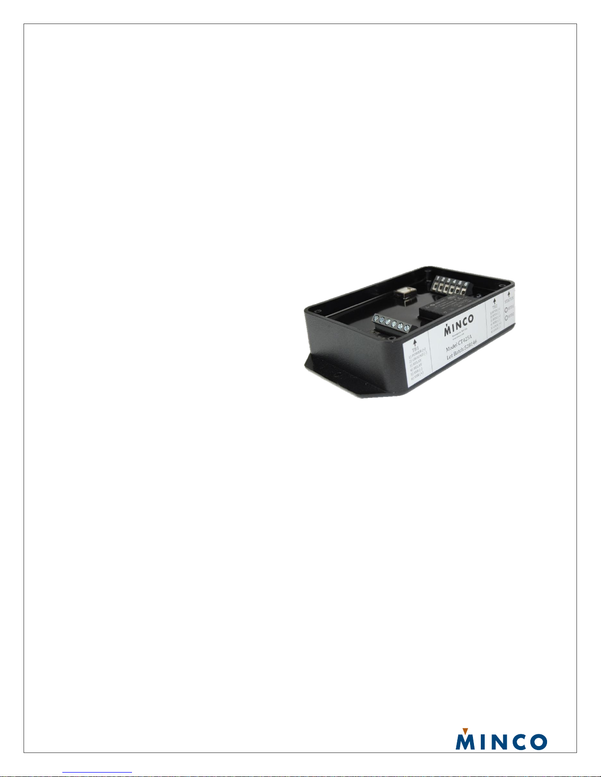
Introduction
The CT425 is a universal temperature controller that supports two platinum RTD inputs and three outputs. Thermistors are
also supported to a limited extent. A 32 bit processor allows up to two PID loops to operate simultaneously at individually
configurable loop rates up to 25Hz. An autotune feature generates PID coefficients, and all configurations are performed
through a Windows application over a USB connection.
Each of the CT425’s three outputs (SSR, LVO, and Relay) has its own set of parameters that may be set independently of
each other, including the use of either RTD input and On/Off, PID, or Alarm function. (PID available on SSR and LVO only)
AC powered models perform zero-cross detection to reduce switching noise on the SSR and LVO outputs.
Conventions
Different typestyles are used throughout this manual to make it easier to convey whether the text refers to a physical feature of
the device, or if it refers to a general term.
A word or phrase with first letter capitalization (such as Relay Output) refers to a feature on the CT425 such as a terminal
block connection or a function feature such as Alarm.
All other typestyles intend to reflect general terms.
Because of the Reverse Acting output feature, specific terms are used to indicate whether an output is in the closed or “on”
state, or if that output is in the active state regardless of the Reverse Acting Relay settings. If referring to whether an output is
closed or providing voltage, “energize” will be used. If referring to if an output is in the active state, which ignores the Reverse
Acting setting and only takes into account the intent of the algorithm, i.e. to turn a heater on when the temperature falls too
low, “engage” will be used.
In other words, “energize” refers to the state of the output at the terminal block, and “engage” refers to what the control
algorithm would normally do when controlling a heater under the given conditions.
Installation
All configurations are performed through the Windows application. The CT425 may be powered through USB if desired. This
allows the user to configure the unit, or simply become familiar without having to connect separate power. Note: the zerocrossing feature is enabled only if AC power is detected when power is applied.
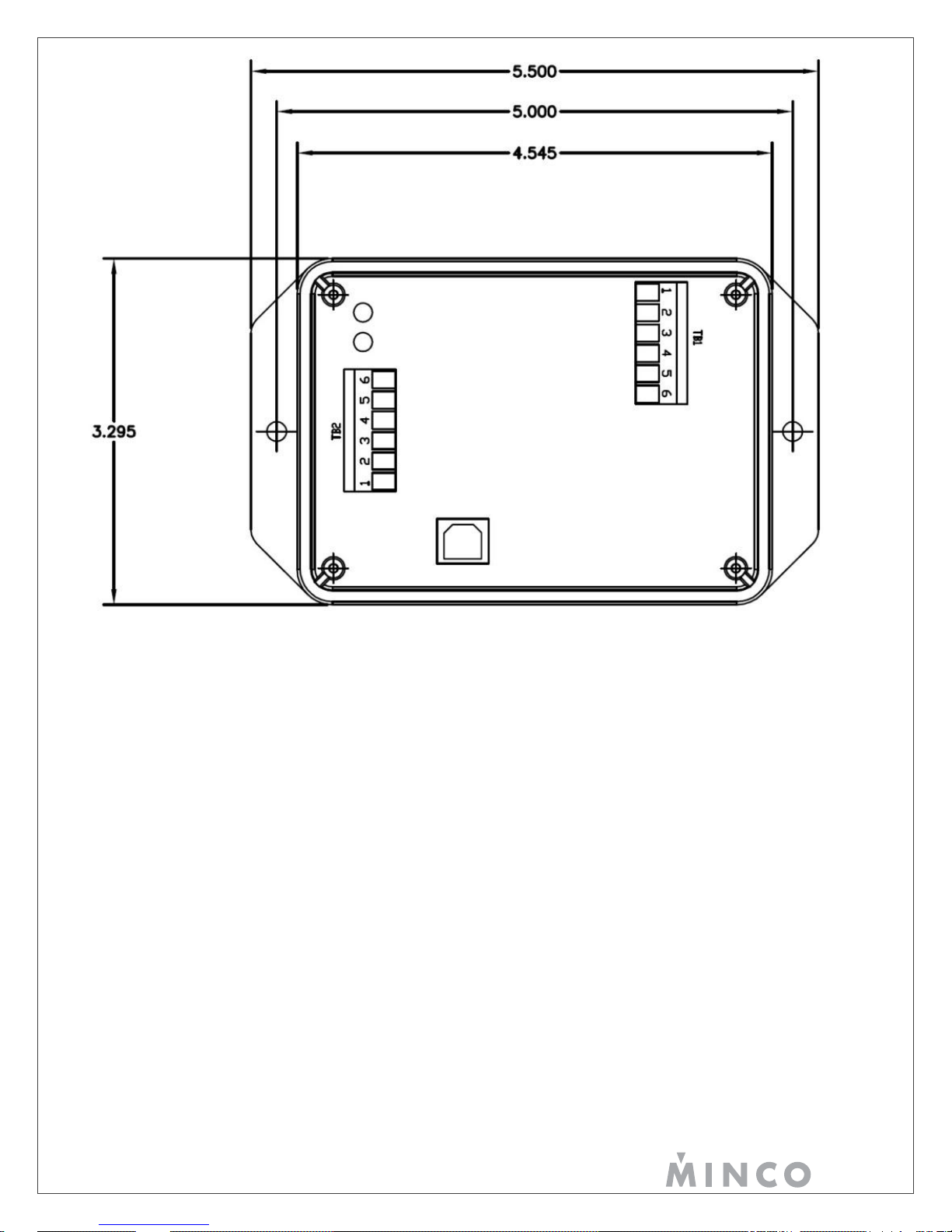
Mounting
The CT425 may be mounted via case flanges if desired, and may be operated in any position.
Wiring
The terminal block connections are shown in Figure 1. Each group of connections is outlined in the following sections.
Page 4
page 2 | © 2013 Minco | 360-00127(C) | minco.com
Figure 1
TB1:1 – POWER (L/+)
TB1:2 – POWER (N/-)
TB1:3 – RELAY CONTACT (N.O.)
TB1:4 – RELAY CONTACT (N.O.)
TB1:5 – SOLID STATE RELAY (-) (AC VERSIONS NON-POLARIZED)
TB1:6 – SOLID STATE RELAY (+) (AC VERSIONS NON-POLARIZED)
TB2:1 – RTD INPUT 1 (+)
TB2:2 – RTD INPUT 1 (-)
TB2:3 – RTD INPUT 2 (+)
TB2:4 – RTD INPUT 2 (-)
TB2:5 – LOGIC VOLTAGE OUTPUT (+)
TB2:6 – LOGIC VOLTAGE OUTPUT (-)
Page 5

page 3 | © 2013 Minco | 360-00127(C) | minco.com
Power
The CT425 is available in AC and DC models. While the external connections appear identical, care must be taken to properly
connect the appropriate power supply.
The power input for the AC model is electrically isolated from the rest of the model’s circuitry. The DC model’s power supply is
NOT electrically isolated from the rest of the model’s circuitry.
AC Model
On AC models, the line and neutral must be connected to the L/+ and N/- terminals, respectively.
DC Model
On DC models, the positive and negative must be connected to the L/+ and N/- terminals, respectively. The power
input has reverse-polarity protection.
Inputs
The CT425 can use any combination of supported sensors which are listed in the table in Sensors.
The sensor inputs are not electrically isolated from the rest of the circuitry; therefore care must be taken to not create a
situation where an unintended short circuit is created.
Each sensor channel has two terminals. The sensor is simply connected to these two terminals. If the sensor has extra wires
for lead compensation, these wires could be left disconnected or grouped together on the same terminal. Lead compensation
may be performed by specifying an offset in the device configuration.
If a shield is provided on a sensor lead, it should be grounded at only one end for best performance. Which end to ground is
usually determined through trial and error since otherwise it is extremely difficult to determine. No terminal is provided for
grounding since the CT425 does not require grounding. Ground at either the sensor end, or add a separate ground wire at the
CT425 end.
Outputs
SSR Output
One SSR output is provided of varying voltage and current ratings depending upon the model. See the table on page
17 for ratings of each model.
The SSR Output is electrically isolated from all other electronics, and will support PID, On/Off, and Alarm functions.
The SSR output on AC models will switch AC or DC current, while the DC model will switch current in one direction
only.
Note that current will always flow in the reverse direction on the DC model SSR output. This may damage the CT425
when carrying higher current levels due to excessive heat dissipation. Ensure the polarity of the SSR load is correct.
Logic Voltage Output
One Logic Voltage Output (LVO) is provided on the devices. The LVO is not electrically isolated from the rest of the
device circuitry; it is intended to drive an external SSR, but could be used for other purposes. The LVO is a currentlimited output and therefore it is not possible to overload this output. However, applying a very low resistance load
during power-up will cause the CT425 to enter a special manufacturing mode which is characterized by alternating
yellow status indicators. If this happens, simply remove the load and re-apply power. See page 16 for specifications.
The LVO will support PID, On/Off, and Alarm functions.
Relay Output
An SPST relay is provided on the CT425. The Relay Output is electrically isolated from the rest of the device’s
circuitry. See the table on page 17 for ratings.
Page 6
page 4 | © 2013 Minco | 360-00127(C) | minco.com
The Relay Output will support On/Off and Alarm functions only. PID is not supported on the Relay Output due to the
possibility of the relay being subjected to frequent switching.
USB
All configurations are performed through the USB interface. The included Windows software communicates with the CT425
and allows the user to configure the unit on the fly, or configure, disconnect, and install the device into the intended
application. All settings may be stored to non-volatile memory so removal of power does not cause loss of configuration.
The USB interface is not electrically isolated.
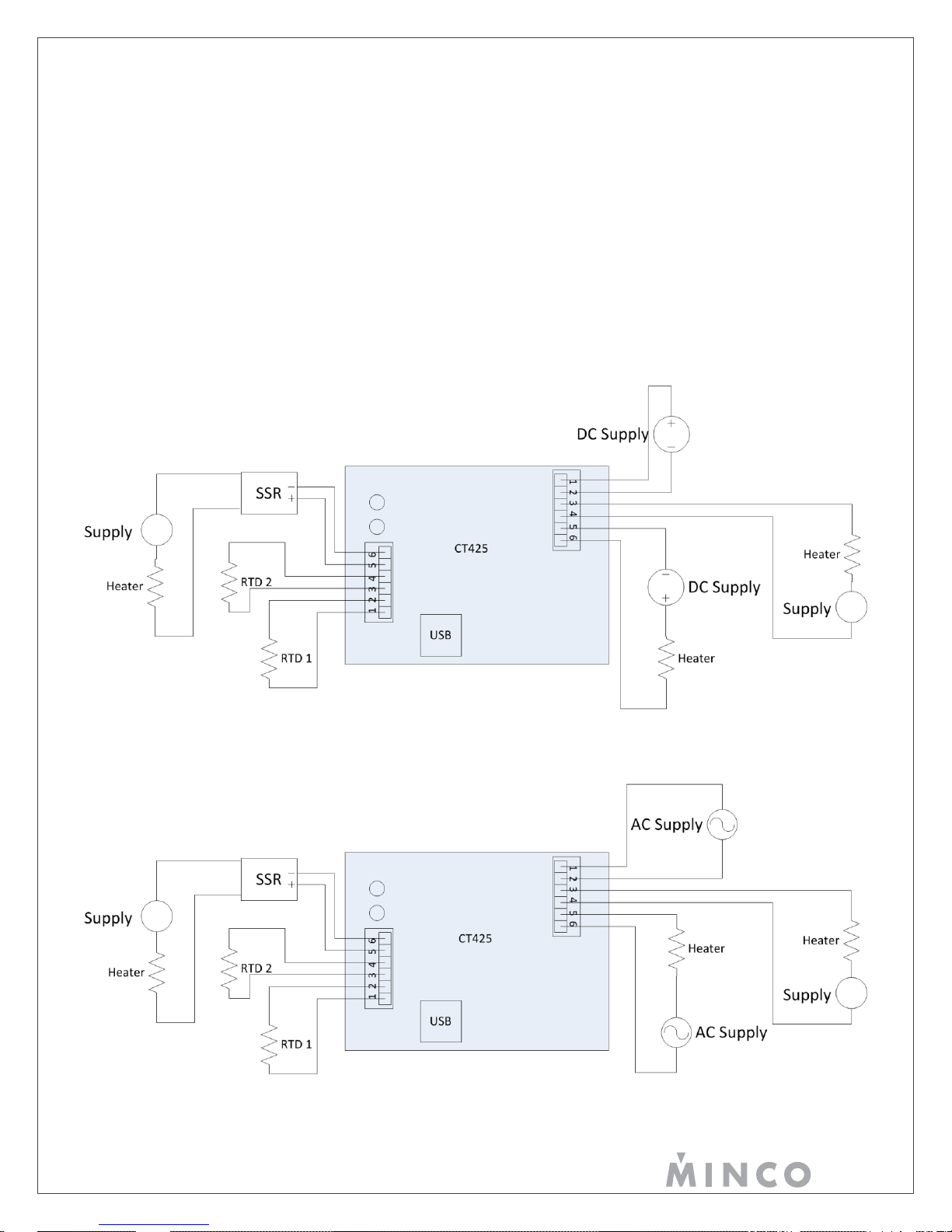
Typical Wiring Diagrams
Below are typical wiring diagrams for DC and AC versions of the CT425. Since the SSR and Relay output are isolated, they
may use the same power supply that powers the device if desired, or a different power supply.
Figure 2
Figure 3
Page 7
page 5 | © 2013 Minco | 360-00127(C) | minco.com
Configuration
Once the CT425 is attached to a computer and the configuration software is started, press “Connect to Device”. If this is
successful, the configuration stored on the CT425 is retrieved and displayed, along with the measured sensor temperature and
output status. The settings are grouped into tabs.
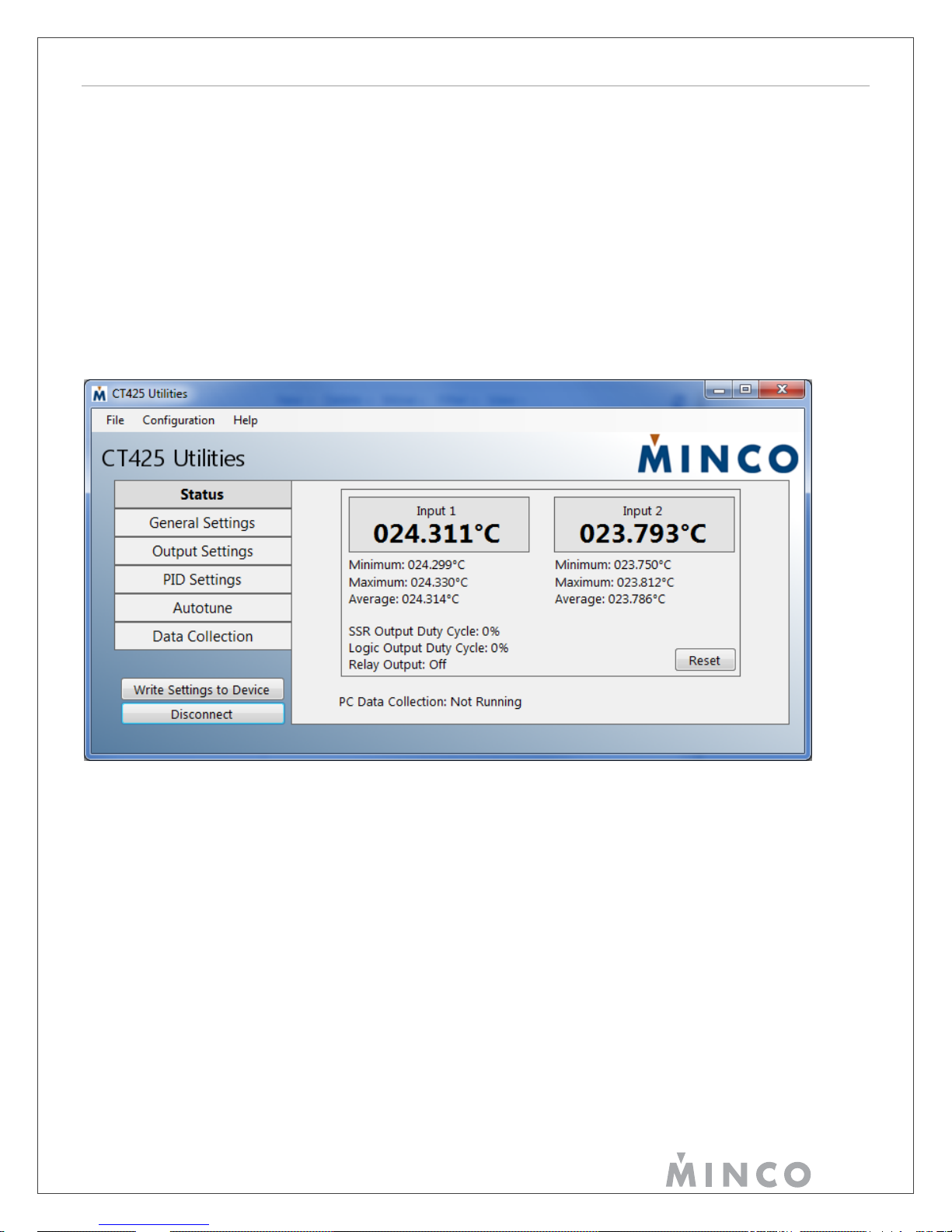
Status
The Status group displays each sensor’s current temperature and each output’s state.
If the read temperature is outside the range of the device, either “Error Lo” or “Error Hi” is displayed if the sensor resistance is
below or above the input range, respectively.
The output status does not take the Reverse Acting setting into account. For example, if the SSR output is at 75% duty cycle,
the output will be energized 75% of the time if Reverse Acting is disabled. If Reverse Acting is enabled, the output will be
energized 25% of the time yet the displayed duty cycle will still be 75%.
Figure 4
General Settings
The General Settings group contains the configuration for the RTD inputs, the temperature scale, and device name.
Device Name: A string of up to 20 characters that the user may change to “name” the device. This may be useful to identify
multiple units.
Temperature Scale: Determines if the CT425 will interact with the user in the Celsius or Fahrenheit scale.
Type: Set to Pt100, Pt1000, Thermistor, or Disabled for platinum 100 ohm, platinum 1000 ohm, thermistors, or no sensor
connected, respectively. See Using Thermistors for more information on thermistor use.
Offset: Applies an offset to the respective sensor input. This could be used for wire lead compensation.
Normal Process Value Range: Defines a temperature range that will cause the sensor input’s Status Indicator to be green,
rather than yellow. This provides a quick visual check as to whether the process is within the user’s desired temperature
range. See the General Usage on page 13 for more Status Indicator information.
Page 8

page 6 | © 2013 Minco | 360-00127(C) | minco.com
Figure 5
Output Settings
The Output Settings group contains the output configuration. Each output has its own tab within Output Settings. Some
options will be unavailable (greyed out) depending upon what function is chosen.
Source: Determines which sensor input the respective output will use. Multiple outputs may share the same sensor input.
Function: Disabled, PID, On/Off, or Alarm.
On/Off and Alarm work similarly with the only difference being how Hysteresis is used. Please see the Hysteresis description
for further information.
When set to Disabled, the output is de-energized regardless of the Reverse Acting setting.
Reverse Acting: Setting this to True causes the respective output to behave in the opposite manner, i.e. normally closed
instead of normally open. This may be useful for cooling applications.
Note that when the output is Disabled, the respective output is de-energized regardless of this setting. Also note that despite
setting Reverse Acting to True, the output will not remain “closed” when the CT425 is unpowered.
Over/Under: Determines whether the output engages when the sensor temperature is over or under the Setpoint. This applies
to the Alarm Function only.
Setpoint: Determines the temperature that the selected sensor input is maintained to for PID and On/Off Functions. In the
case of the Alarm Function, when the sensor is above or below this temperature the output will activate depending upon if
Over or Under is selected, respectively.
Hysteresis: Determines the band around the Setpoint where the output engages and disengages.
When using the On/Off function, the Hysteresis value is evenly divided around the Setpoint. For example, if the Setpoint is
55.0C and Hysteresis is 0.1C, the output will engage at 49.95C, and disengage at 55.05C.
When using the Alarm function, the Hysteresis is placed on the side of the Setpoint that does not engage the output. For
example, if the Setpoint is 55C, Over/Under is Over, and Hysteresis is 0.1C, the output will engage when the sensor exceeds
55.0C, but will disengage when the sensor is less than 54.9C.
Page 9

page 7 | © 2013 Minco | 360-00127(C) | minco.com
The hysteresis value is meaningless to the PID Function and therefore is greyed out if that Function is used.
NOTE: To avoid frequent cycling, set the Hysteresis high enough when using the Relay Output.
Minimum Duty Cycle: Determines the minimum duty cycle, in percent, that the output will reach. This is the duty cycle at the
output terminals with respect to the Reverse Acting setting. Normally this value is set to zero, however there may be some
applications that require a minimum of more than zero. When the Function is set to Disabled, this setting is irrelevant.
Maximum Duty Cycle: Determines the maximum duty cycle, in percent, that the output will reach. This is the duty cycle at the
output terminals with respect to the Reverse Acting setting. Normally this value is set to 100; however there may be some
applications that require a maximum of less than 100. When the Function is set to Disabled, this setting is irrelevant.
Figure 6
PID Settings
The PID Settings group contains settings specific to the PID Function. These settings will be unavailable unless the respective
output is set to the PID Function.
Method: Determines if the PID coefficients (Kp, Ki, Kd) will be entered manually by the user, or if they will be automatically
generated from Autotune data by one of several algorithms.
The information gained from an Autotune procedure is saved so the Method may be changed later by the user. As with all
other settings, this is preserved through a power cycle only if written to nonvolatile memory.
It should be noted that the various options listed in Method are the common names given to the various algorithms. For
example, Minimal Overshoot may or may not result in the least overshoot among the other available methods due to variability
in application, and accuracy of the Autotune performed. It’s recommended to try different Methods to find the best performer,
and if desired, manually tweak from there.
An easy, though generic option is to simply set Kp, Ki, and Kd to 100, 2, and 0, respectively. These are the default values the
CT425 are shipped with, and work reasonably well in many applications. Kd could instead be set to 1000 for full PID. Again,
these values are generic and are by no means intended to work in every application.
Kp: The Proportional coefficient.
Page 10

page 8 | © 2013 Minco | 360-00127(C) | minco.com
Ki: The Integral coefficient.
Kd: The Derivative coefficient.
Loop Time: The loop time for the PID Function, in milliseconds. This is the amount of time between each PID Function
calculation, i.e. how often output duty cycle is recalculated based on current conditions. A lower number will theoretically
result in faster response time. However, a Loop Time that is too low may result in an unstable system. In general, slow
moving processes should have a higher Loop Time.
Figure 7
Autotune
The Autotune group contains settings for the Autotune feature.
Autotune Band: Determines the number of degrees above and below the Intended Setpoint the output is toggled during
Autotuning, respectively. Generally this should be set as high as tolerable to improve Autotune results, although 0.5°C is
frequently sufficient. See the How Autotune Works section on page 10 for more information.
Autotune Output Step: Determines the output duty cycle while the output is engaged. The Autotune algorithm will cycle the
output between fully de-energized (“off”) and the Output Step. The purpose of the Autotune Output Step is to limit heater
power in applications where 100% duty cycle would cause very rapid heating, making autotuning difficult.
In general, set this value as low as possible while allowing the heater to receive enough power to reach the intended
temperatures. See the How Autotune Works section on page 10 for more information.
Intended Setpoint: Determines the temperature around which the Autotune algorithm will operate. The purpose of this value
is to first bring the heater to the approximate temperature at which it would normally be operated before Autotuning, which may
improve Autotune results.
Be aware that simple on/off control is used while autotuning, and it’s possible that significant overshoot will occur during this
Autotune step if the Autotune Output Step is set too high.
Page 11

page 9 | © 2013 Minco | 360-00127(C) | minco.com
Figure 8
How Autotune Works
The Autotune feature automatically generates PID coefficients based on measurements performed using the actual sensor
and load. Sometimes the values generated by Auto Tune are sufficient as the final operating values, but for better control,
these may have to be manually tweaked.
The CT425 Autotune functions use the Ziegler-Nichols method. Autotune operates by first engaging the output to the duty
cycle defined by Autotune Output Step until the temperature reaches the Intended Setpoint. This step is indicated by
displaying “Pre-Heating”. The output is left in the engaged state until the temperature exceeds the sum of Intended Setpoint
and Autotune Band. The output is disengaged, and the temperature will begin to fall and the output is engaged again once the
temperature is less than the difference between Intended Setpoint and Autotune Band. During this step, “Determining Cycle
Rate” is displayed; the CT425 is measuring the approximate time required for a full temperature swing.
The output then continues to cycle in the same manner while displaying “Cycle x”, where “x” is the cycle number. This gives
the user an idea of how far along the Autotune process is.
Essentially, the output is toggled to cause the temperature to vary above and below the Intended Setpoint by approximately
the Autotune Band. This process is repeated several times until the results are consistent.
The time between temperature peaks, the difference between temperature peaks and valleys, and the output drive duty cycle
are used to determine PID coefficients.
Regardless of what Method is used to automatically generate the PID parameters, the above process is the same. The only
difference is how the measured behavior is used to calculate the coefficients.
Once Autotuning is complete, control is immediately returned to the Function selected for that output.
Data Logging
The CT425 includes two methods of data logging: On-Board, and PC. The intended purpose of these two data loggers is
different.
The On-Board logger runs continuously and transparently in a loop, storing a number of the most recent samples. Should
something unexpected happen, a computer may be connected to the device and the contents downloaded for analysis.
Page 12

page 10 | © 2013 Minco | 360-00127(C) | minco.com
The PC logger is part of the Windows utility program and simply polls the CT425 on a continual basis, then directly saves the
temperature readings to a CSV file.
See below sections for more information.
On-board Data Logger
The On-board logger is active as long as the CT425 is powered. It does not affect any other function and therefore, is
completely transparent to the user. The On-board logger uses the circular buffer concept which means that once the entire
available memory is filled with samples, the oldest data is overwritten with new data. This will store a number of the most
recent samples, with the older samples overwritten with newer data. The On-board logger utilizes only two settings:
Data Sources: Determines what data is logged. Channel 1, Channel 2, and Outputs each require one position in the Onboard logger memory, and are written simultaneously. Enable only those data sources required in order to maximize the
number of useful data stored. For example, if all three data sources are enabled, the On-board logger will begin overwriting
old data in one-third the time compared to enabling only one data source.
If this setting is changed, all samples stored in the On-board logger will be erased; this is done to ensure the nature of the
recorded data is homogenous.
The utility program will calculate the number of sample groups that can be stored before overwriting older ones, and will also
display the amount of time before this happens based on the displayed settings. A sample group consists of samples selected
in Data Sources.
Period: Determines the time between each group of samples. For example, if both channels are enabled in Data Sources
and this value is set to 40ms, both sensor inputs will be sampled simultaneously every 40ms. Because two items are enabled
in Data sources, two data logger memory locations will be used every 40ms. If one item in Data Sources is selected, only one
memory location would be used every 40ms.
If this setting is changed, all samples stored in the On-board logger will be erased; this is done to ensure the nature of the
recorded data is homogenous.
To download the On-board Data Logger’s data from the device, simply connect the utility program and click Download Data
from within the On-board Data Collection tab in the Data Collection group. The Download Data button is not visible if any Onboard logger settings are modified and not written. See Figure 9. Data logging will be momentarily halted while the entire data
logger buffer is downloaded to a file. The data logger buffer will also be cleared to maintain time continuity in the stored
samples.
Note that the On-board Data Logger retains its stored samples only as long as power is applied. All recorded samples are lost
if power to the CT425 is lost.
Page 13

page 11 | © 2013 Minco | 360-00127(C) | minco.com
Figure 9
PC Data Logger
The PC Data Collection tab in the Data Collection group contains settings for the PC logger. The CT425 must be connected to
the host computer when using the PC Data Logger since data is immediately stored on the host computer.
The generated file format is CSV. After specifying the collection parameters, press the Start button to begin data collection.
The device will continue to perform all other activities while data collection is active. However, Autotune cannot be started
while using the PC Data Logger.
Figure 10
Page 14

page 12 | © 2013 Minco | 360-00127(C) | minco.com
While collecting data, it is possible to view a real-time graph of the data by clicking ‘Show Graph’ before data collection. The
graph displays only the selected channels both on the Graph pane and the Data Sources pane from the PC Data Collection
tab. The line color for each line can be changed by clicking the color palette square located leftmost to on the legend. It is
important to note that there are two scales – temperature and output percentage. Channel 1 and 2 output temperatures use
the leftmost scale and the outputs use the right scale. To fit the data, right click on the chart area and select ‘Set Scale to
Default’. You can also zoom by left clicking and dragging or pan by middle mouse and drag.
Figure 11
Submitting Settings
The Write Settings to Device button submits all changes that have been made within the utility program to the devices nonvolatile memory. The user may make changes to multiple groups and tabs, however the CT425 does not receive these
changes until this button is pressed; once it is, all changes in all groups and tabs are submitted to the device.
The text on the Write Settings to Device button will turn red when the device configuration does not match the software’s
configuration. After selecting, the button will turn black again. This color change to red serves to remind the user that a
configuration is not yet active on the CT425.
The Write Settings to Device button commands the CT425 to commit the changes directly into non-volatile memory. This
means that if the CT425 loses power, it will power up with this configuration. Performing this function while running a high
Page 15

page 13 | © 2013 Minco | 360-00127(C) | minco.com
speed PID loop could possibly disrupt it; the function halts all operations for a maximum of 30ms. Although this is unlikely to
Indicator
Color
Pattern
Meaning
RTD1 or RTD2
Green
Solid
This sensor input is enabled, and temperature is within user configured Normal Process Value
Range.
RTD1 or RTD2
Yellow
Solid
This sensor input is enabled and reading a valid value, but the temperature is not within user
configured Normal Process Value Range.
RTD1 or RTD2
Red
Solid
This sensor input is enabled; however sensor is out of range. Check sensor connections and
configuration.
RTD1 and RTD2
Red
Blink
A hardware failure has occurred. All outputs de-energized. Both status indicators blink in unison.
See the errors section on page 15 for more information.
RTD1 and RTD2
Yellow
Blink
CT425 is in manufacturing mode. Status indicators alternately blink yellow. Ensure LVO isn’t
shorted through low resistance.
RTD1 or RTD2
Off
N/A
No outputs configured to use this sensor input.
cause any issue, the user could disconnect the loads first to be safe.
As an example, assume the user has a CT425 they wish to use in a heating application. It will be connected to a sensor,
heater, and source of power, but won’t be connected to a computer. First the user connects the CT425 to their computer in
order to configure the sensor types, outputs, set point, etc.; everything is configured as desired for this heating application.
The Write Settings to Device button is pressed so this configuration is automatically loaded and used the next time power is
applied to the device.
General Usage
Status Indicators
Upon application of power, the two status indicators RTD1 STATUS and RTD2 STATUS display a pattern of red then green.
This assures the user that the status indicators and device circuitry are functioning.
Each status indicator corresponds to the RTD1 Input and RTD2 Input in general. There are two situations in which the action
of the status indicators does not indicate the status of its respective RTD Input, but rather a general CT425 error or situation.
The legend for the status indicators is shown Table 1.
Table 1
Output Behavior
The SSR and LVO behave differently depending if they are in AC mode or DC mode; the Relay Output is unaffected. The
CT425 DC models are always in DC mode, but an AC model may be in either mode.
The output mode is determined each time power is applied to the device. When power is applied, a frequency measurement
is taken on the power input terminals. If the minimum frequency threshold is detected, the CT425 will start in AC mode;
otherwise it will be in DC mode. When powered only from USB, DC mode will always be detected due to the lack of an AC
waveform. If initially powered from USB, the CT425 will remain in DC mode even if an AC power supply is later connected to
the power input terminals. The AC/DC mode determination is made each time the device is powered up.
NOTE: Do not initially power a device with AC power then switch to exclusively DC power while driving a load on the SSR or
LVO. The CT425 will not switch to DC mode and therefore, the SSR and LVO outputs will cease to function, potentially
causing damage to the attached load.
DC Mode
In DC mode the SSR and LVO are driven by a fixed-frequency PWM signal. The duty cycle will vary based on the output drive
requested by the selected function. The frequency and duty cycle specifications are listed on page 17 under PWM Output
Characteristics.
Page 16

page 14 | © 2013 Minco | 360-00127(C) | minco.com
AC Mode
In an effort to reduce switching noise, the CT425 will switch the SSR and LVO at the zero crossings (ZC) when in AC mode.
This behavior applies to any function (PID, On/Off, Alarm). The Relay Output does not perform ZC switching due to the
impracticality of doing so with mechanical contacts.
ZC switching is generally the preferred method to switch AC loads since the transitions are performed when the AC voltage is
near zero volts.
A disadvantage of ZC switching is the PWM duty cycle resolution is decreased. For example, with 60Hz power there are only
120 opportunities per second to switch the output. While this results in a duty cycle resolution of 0.833%, in DC mode the duty
cycle resolution is much higher. However, achieving better resolution in AC mode would mean disabling zero-cross switching
and would result in an inconsistent and unpredictable amount of energy during the output “on” time; something that is
important for good PID control.
For further explanation of how ZC detection works, see Error! Reference source not found.. The red “Requested Control”
trace represents the SSR or LVO in DC mode; this is what the control algorithm is actually requesting. The green “Zero-Cross
Aligned Control” is the adjusted output where transitions occur at the zero cross points. The resulting AC output is shown on
the last waveform; switching occurs only when the voltage is near zero.
It’s important to use the rated AC voltage with the SSR for accurate ZC switching. Using a substantially different voltage may
result in switching that doesn’t occur at the zero crossings. This should not damage the CT425 provided maximum voltage
ratings are observed, but does somewhat negate the advantage of ZC switching.
Figure 12
Page 17

page 15 | © 2013 Minco | 360-00127(C) | minco.com
Errors
Status LEDs
The Status LEDs normally indicate sensor status, but analog-to-digital converter failure is indicated by both LEDs blinking red
in unison. When this occurs, all outputs are set to the de-energized state and the device must be power-cycled to reset it.
This situation may indicate permanent hardware failure; however more often it will indicate insufficient supply voltage is
present. Ensure the CT425 is receiving proper supply voltage and try cycling the power.
Another possible situation the Status LEDs can indicate is if the CT425 is in manufacturing mode. This is characterized by
rapidly alternating yellow Status LEDs, and occurs if a very low resistance is present across the LVO during application of
power. This is not a fault or error, but rather a mode invoked during manufacturing for the purpose of programming the unit.
Ensure the load across the LVO is greater than the specification in Logic Voltage Output, then cycle power.
Multiple Units
The CT425 Utilities software checks if multiple units are connected to the same computer when a user connects. From this
dialog, the user can either configure a single unit or data log from multiple units (up to 5).
Figure 13
When data logging with multiple units, a new form opens which displays all of the data collections settings similar to the PC
data logger. Note that the minimum sample rate is increased to 100mS multiplied by the number of devices. During data
collection, this form also shows real-time readings of all devices and can graph the data.
Figure 14
Page 18

page 16 | © 2013 Minco | 360-00127(C) | minco.com
Bluetooth Low Energy (-BT Option Only)
Overview
A Bluetooth Low Energy (BLE) modem has been included on the CT425 to allow wirelessly viewing of temperatures and
changing of set points using an Android or Apple smartphone. The primary purpose of this is to monitor real-time operation of
the CT425 without using a PC because the CT425 does not have a display. It is important to note that the PC software is
required to initially configure the CT425 with sensor types, output types, etc. as this cannot be completed from the smartphone
applications.
The CT425 uses a Class 2 Bluetooth Low Energy radio.
Android Application
An Android smartphone with BLE support (Android version 4.3 and higher) can be used to connect to the CT425. First, install
CT425 Utilities from the Google Play Store. With Bluetooth powered on, open up the application and scan for devices by
selecting Scan on the top right (Figure 15). Bluetooth Low Energy (BLE) devices in range will be populated in a table which
can be accessed by three vertical dots that appear next to the scan button (if the three dots do not appear, no devices have
been found). Tap the name of the CT425 device (Figure 16) to connect to it.
Figure 15 Figure 16
Page 19

page 17 | © 2013 Minco | 360-00127(C) | minco.com
Wait for several seconds as the phone attempts to connect to the CT425. When a device is properly connected, “Scan” will
change to “Disconnect” and temperatures will appear (Figure 17). To change units and setpoints, select the Settings button
and change the appropriate settings. The CT425 is updated when the Save button is selected. Then use the back key to return
to the previous screen.
Figure 17 Figure 18
When finished, disconnect the CT425 by selecting Disconnect and then closing the application.
Page 20

page 18 | © 2013 Minco | 360-00127(C) | minco.com
iOS Application
An iPhone 4S or newer iPhone can be used to connect to the CT425. From the App Store, download the CT425 Utilities App.
With Bluetooth powered on, open the CT425 Utilities application and scan for devices by selecting Scan on the top left.
Bluetooth Low Energy (BLE) devices in range will be populated on the table (Figure 19). Tap the name of your CT425 to
connect to it.
Figure 19
Wait for several seconds as the phone attempts to connect to the CT425. If after ~4 seconds a successful connection has not
been made, press Connect on the top right again. Repeat this process if necessary. You may have to move closer to the
CT425 if many attempts are made without achieving a solid, reliable connection. Temperatures and setpoints will appear when
connected (Figure 20). Basic settings can be changed by selecting Device Settings.
Figure 20 Figure 21
When finished, disconnect the CT425 by selecting Disconnect and then closing the application.
Page 21

page 19 | © 2013 Minco | 360-00127(C) | minco.com
Frequently Asked Questions (FAQ)
Q: Is a USB connection to a computer required for the CT425 to operate correctly?
A: No. The CT425 itself does not rely on the USB connection for any function.
Q: How long will the CT425 maintain a configuration in non-volatile memory?
A: The specification states the retention is at least 20 years and will withstand almost 1 million writes.
Q: Why am I getting a “Device Not Recognized”, or why is the utility program not connecting?
A: Try unplugging the USB cable, close the utility program, and wait at least 10 seconds before reconnecting.
Q: Why are the STATUS indicators blinking yellow and nothing works?
A: Check what is connected to the LVO. A low resistance across that output will cause this.
Q: I have a 3 or 4 wire RTD, but the CT425 only provides two connections. Can these RTDs be used?
A: Yes. Either the extra wires can be left disconnected, or they can be grouped together.
Q: Why is autotuning taking so long? It’s well beyond Cycle 3 or 4, and it’s still not done.
A: Try reducing the Autotune Output Step and/or increasing the Autotune Band.
Q: Why is the SSR output conducting current even though it’s off?
A: If this is a DC unit, it’s likely the SSR wiring polarity is reversed.
Q: Can an external SSR be connected directly to the LVO?
A: In most cases, yes. Many external SSRs, including the ones sold by Minco, will operate correctly this way.
Q: Will data logging, downloading data, or disconnecting the USB cable disrupt output functions?
A: As long as the device continues to receive power, none of these functions are affected.
Using Thermistors
A provision to use thermistors is now available on the CT425. The thermistor’s resistance must essentially fall within the range
of a platinum 1000Ω RTD. Most thermistors will exceed the resistance of the aforementioned RTD, therefore an option is
provided to place a resistor in parallel with the thermistor. This effectively reduces the resistance range of the thermistor, and
since the user must provide the parallel resistor’s value, the CT425 is able to calculate the actual thermistor resistance.
There are two ways to configure the CT425 to use thermistors: by entering Steinhart-Hart coefficients, or by entering
temperature-resistance pairs. Some thermistor datasheets will provide Steinhart-Hart coefficients. This is a set of three
numbers that describe the temperature-resistance relationship, and these values may be directly entered into CT425 Utilities
once at least one input has been set to type Thermistor.
If Steinhart-Hart coefficients are not available, temperature-resistance pairs may be entered. To do this, click on Thermistor
Calculator, then enter three temperature-resistance pairs. It’s best to choose values such that one is the minimum and one is
the maximum temperature that will be measured. The third value should be about halfway between these two.
Finally, a parallel resistor may be required such that the resistance is within measurable range. This resistance is entered into
the CT425 Utilities (see Figure 22), and the temperature range that the CT425 is capable of measuring given the thermistor
properties and parallel resistor is calculated and displayed. A resistor of the same value entered must be connected across
the thermistor connections.
Page 22

page 20 | © 2013 Minco | 360-00127(C) | minco.com
If both inputs are configured for Thermistor, the CT425 will assume both thermistors are the same type and same parallel
resistor.
Note that the Thermistor function is not calibrated; only platinum RTD is. Measurement accuracy is typically within 0.5C of the
true value, but it’s not guaranteed nor characterized.
Figure 22
Specifications
Inputs
Power
Option A: 120 VAC 50/60Hz, 3.25W maximum
Option B: 10.5 to 60 VDC, 1.75W maximum
Option C: 240 VAC 50/60Hz 3.75W maximum
Any model may be powered through USB, 200mA maximum.
The power input is electrically isolated on AC powered models only, up to 3KV AC. The power input on DC models and the
USB connection are not isolated.
Sensors
1 or 2 RTDs in any combination, -70C° to 650C° (-70F° to 1202F°)
PD/PE (100Ω @ 0°C, 0.00385Ω/Ω/C°)
PF (1000Ω @0°C, 0.00385Ω/Ω/C°)
Thermistors may also be used provided their resistance can be limited to the range of 700Ω – 3300Ω by attaching a parallel
resistor. Note that the CT425 is calibrated for RTDs only, therefore thermistor accuracy is not guaranteed.
Page 23

page 21 | © 2013 Minco | 360-00127(C) | minco.com
Outputs
Ambient
25°C
55°C
Model
CT425A
CT425B
CT425C
CT425A
CT425B
CT425C
Current Rating
6 amps
15 amps
3 amps
5 amps
11 amps
2.5 amp
Voltage Rating
120VAC
60VDC
240VAC
120VAC
60VDC
240VAC
Relay Rating
10 amps, resistive
SSR
Electrically isolated to 2500V RMS.
Logic Voltage Output
“On” open circuit voltage: 4.4VDC +/- 0.1V
Internally limited to 26mA, +/- 3mA
Minimum load resistance allowed without entering manufacturing mode: 12 Ω
Internally, LVO is connected through approximately 29Ω resistance along with a current limit circuit.
Relays
240VAC or 30VDC, 10A resistive
PWM Output Characteristics
These characteristics apply to SSR and LVO only.
PWM output frequency (DC mode only): 25Hz
PWM duty cycle range (DC mode only): 0.0% to 100.0% (1000 steps)
In AC mode, the PWM output frequency follows the power source, and duty cycle range is 0.0% to 100.0% over a number of
steps equal to twice the frequency.
Minimum power supply frequency to start in AC mode: 47Hz
Communication
USB 2.0, Type B
Bluetooth Low Energy, Class 2 (-BT version only), 10m range independent of orientation, assuming direct line-of-sight.
Data Logger
Internal Data Logger
Capacity: Hardware Version 1.0: 14,136 total samples
Hardware Version 1.1: 28,272 total samples
Resolution: 0.1°C / 0.18°F
Sample rate: 40ms to 49.7 days in one millisecond increments
Type: Circular buffer (oldest sample overwritten with new sample)
Utility Program Data Logger
Capacity: Limited only by host computer disk space
Resolution: 0.01°C / 0.018°F
Page 24

page 22 | © 2013 Minco | 360-00127(C) | minco.com
Period range: 100ms to 60 minutes in one milliseconds increments
CSV
Comma Separated Values: A method of storing data in a file where each value is separated by
commas. Most spreadsheets will directly read this format into spreadsheet columns.
LED
Light Emitting Diode: A solid state device that converts electricity directly into light.
LVO
Logic Voltage Output: A digital output that is typically used to control another device such as an
external SSR.
PID
Proportional Integral Derivative: A control algorithm that uses present error, cumulative error, and error
rate of change to control the process.
RTD
Resistance Temperature Detector: A variable resistor that changes resistance based on temperature.
SPST
Single Pole Single Throw: The simplest switch configuration, having two connections and providing
simple on/off functionality.
SSR
Solid State Relay: A type of relay without mechanical contacts constructed from solid state
components.
USB
Universal Serial Bus: A common computer interface on computers for interfacing to various
peripherals.
Type: Read and store to host PC disk
General
Resolution
Temperature displayed to 0.01 degree (°C or °F)
Accuracy
At 25°C (77°F) ambient temperature:
+/- 0.25°C (0.45°F) or +/- 0.25% over entire input range
Over entire rated ambient temperature:
+/- 1.5°C (2.7°F) or +/- 1% over entire input range
Dimensions
5.46"L x 3.34"W x 1.22"D (13.87cm L x 8.48cm W x 3.10cm D)
Weight
Approximately 0.35Kg (12.3 ounces)
Environmental
Operating temperature: -25 to 55°C (-13 to 131°F) @ 90% relative humidity, non-condensing
Storage temperature: -40 to 85°C (-40 to 185°F) @ 90% relative humidity, non-condensing
Construction
Potted plastic enclosure with plastic mounting flanges and terminal blocks.
Glossary
 Loading...