

Page 1
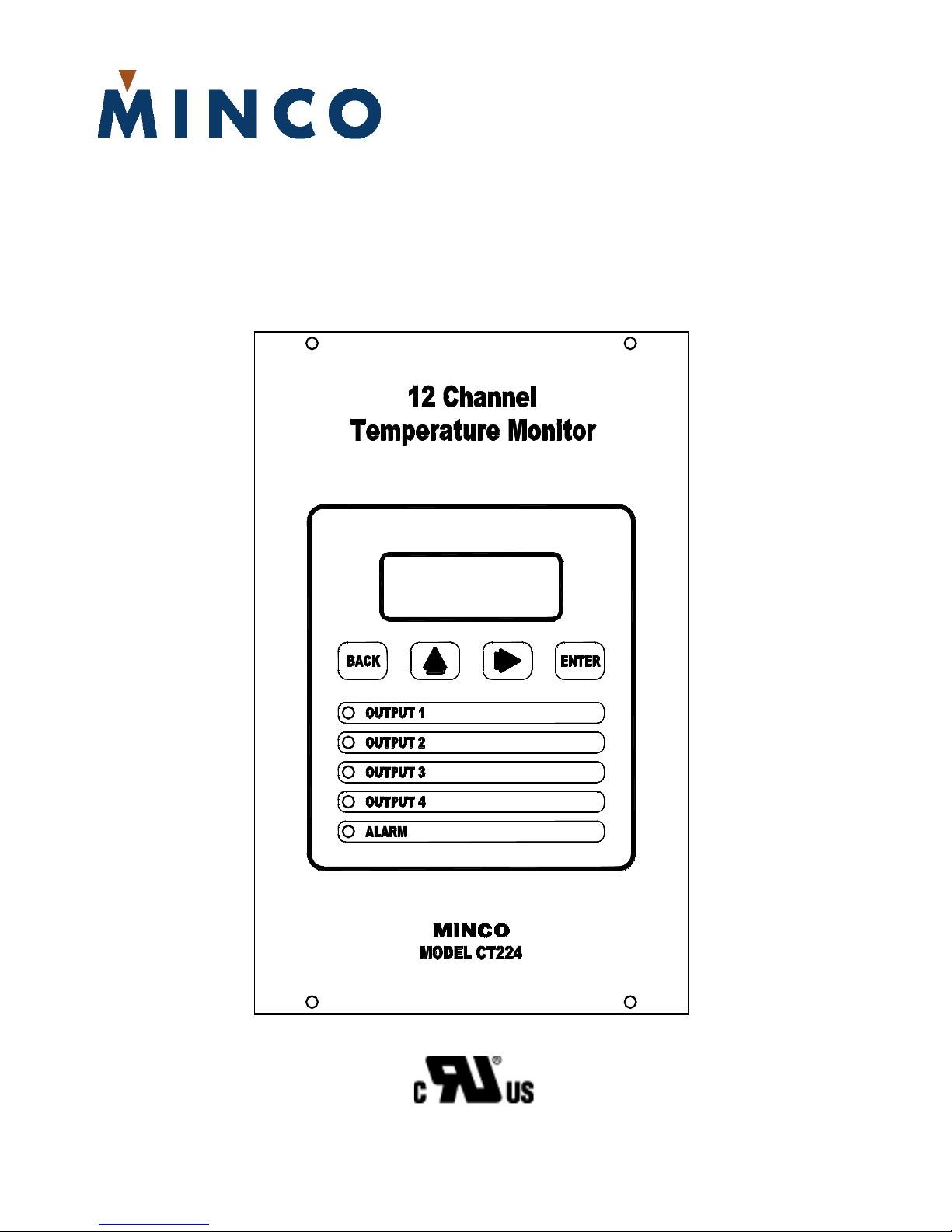
CT224
12-Channel Temperature Monitor
Installation and Operating Instructions
Tel: 763.571.3121 • Fax: 763.571.0927 • www.minco.com
Page 2

This page left blank intentionally.
Minco Tel: 763.571.3121 • Fax: 763.571.0927 • www.minco.com 2
Page 3

Table Of Contents
1. Introduction
2. Pre-Installation
3. Installation
A. Mounting
B. Wiring
1.) Controller Power
2.) Inputs
3.) Outputs
4.) Serial Communications
4. Programming Configuration
A. Using the CT224
1.) Modes / Buttons
B. Entering the Program Settings
C. Setup Worksheet
5. Communications
A. Function Codes
B. Memory Map
6. Specifications
Minco Tel: 763.571.3121 • Fax: 763.571.0927 • www.minco.com 3
Page 4

1. Introduction
The CT224 is a universal 12-channel monitor capable of monitoring inputs for any combination of
RTDs, Thermocouples, and 4-20mA loop inputs. The CT224 has 5 outputs, 4 of the outputs can be
used for warning or shutdown signals, the other output is dedicated to signaling alarm conditions.
One internal audible alarm is also present. RS485 or RS232 Serial Communications is also included
on the CT224 and allows use of the Modbus Protocol to communicate data with another device.
MincoSoft CT224 Software is also provided to allow easy communication with the CT224 by using a
computer.
Minco Tel: 763.571.3121 • Fax: 763.571.0927 • www.minco.com 4
Page 5
2. Pre-Installation
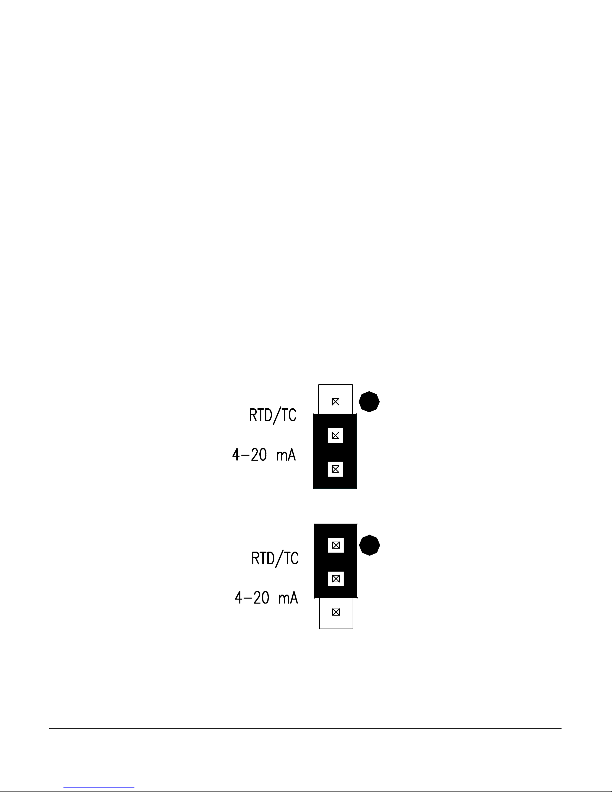
Figure 1
– Jumper
in position for 4
-
20mA Inputs
The first step before installing the CT224 is to determine the input types that will be used. If analog
4-20mA signals will be used as inputs, jumpers under the rear cover will need to be changed. When
received, the jumpers are set to allow RTD and thermocouple inputs on all input channels. Analog
inputs require that the jumpers be moved to the 4-20mA setting. Follow the simple steps below to
allow 4-20mA loop inputs:
1. Remove the 4 screws that hold the rear cover on. (Do not remove the other 4 screws
that go directly through the board.)
2. Set the rear cover aside.
3. Look at the top of the CT224. There is one jumper for each channel located next to the
corresponding channels terminal block. For all of the channels that will be used for 420mA inputs, set the jumper to the position away from the dot. Figure 1 shows a
jumper in the position to allow 4-20mA loops. Leave the jumpers for the other
channels that will be used for RTDs and thermocouples in the dot position. Figure 2
shows a jumper in the position for RTD and Thermocouple inputs.
4. Replace the rear cover and screws.
The CT224 is now ready to accept 4-20mA inputs on the channels that are set like the jumper shown
in Figure 1.
Figure 2 – Jumper in position for RTD or Thermocouple Inputs
Minco Tel: 763.571.3121 • Fax: 763.571.0927 • www.minco.com 5
Page 6
3. Installation
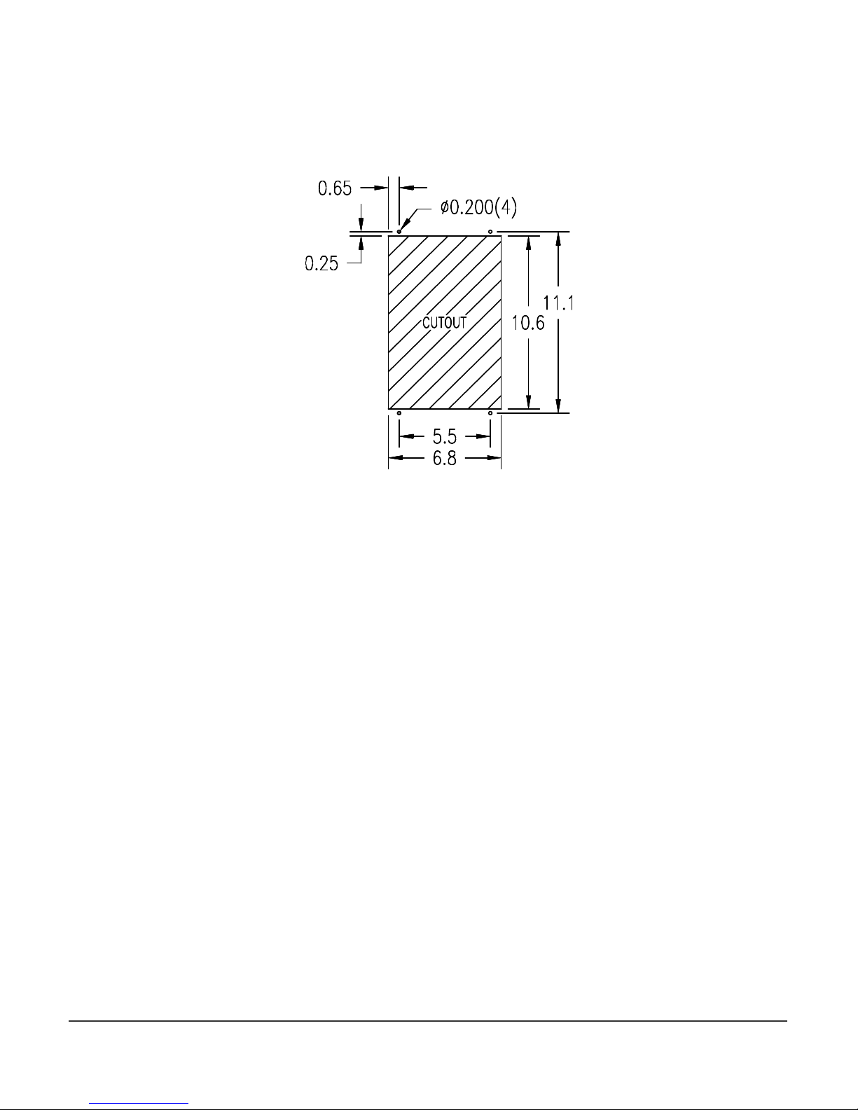
A. Mounting
Make a rectangular cut out in the panel where the CT224 will be located. The cutout should
be made according to Figure 3.
Slide the CT224 into the cut out, drill holes for the screws or bolts that will fasten the unit to
the panel. Be sure that the gasket around the CT224 is compressed between the front cover
and the panel so that liquid and debris cannot get behind and inside of the panel.
Figure 3 – Panel Cutout
Minco Tel: 763.571.3121 • Fax: 763.571.0927 • www.minco.com 6
Page 7
B. Wiring
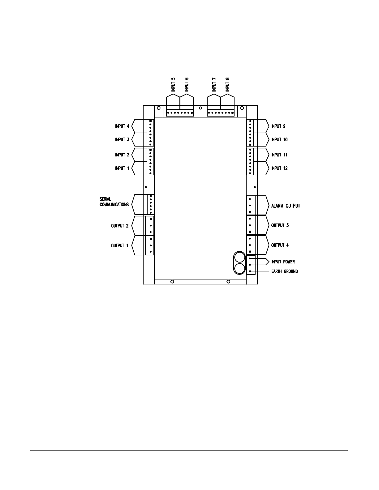
The locations of the connections on the CT224 are shown in Figure 4. The rear cover of the
CT224 also shows the connections for each terminal. More detail for each of the connections
is given in the following sections.
Figure 4 – Wiring Connection Locations
Minco Tel: 763.571.3121 • Fax: 763.571.0927 • www.minco.com 7
Page 8
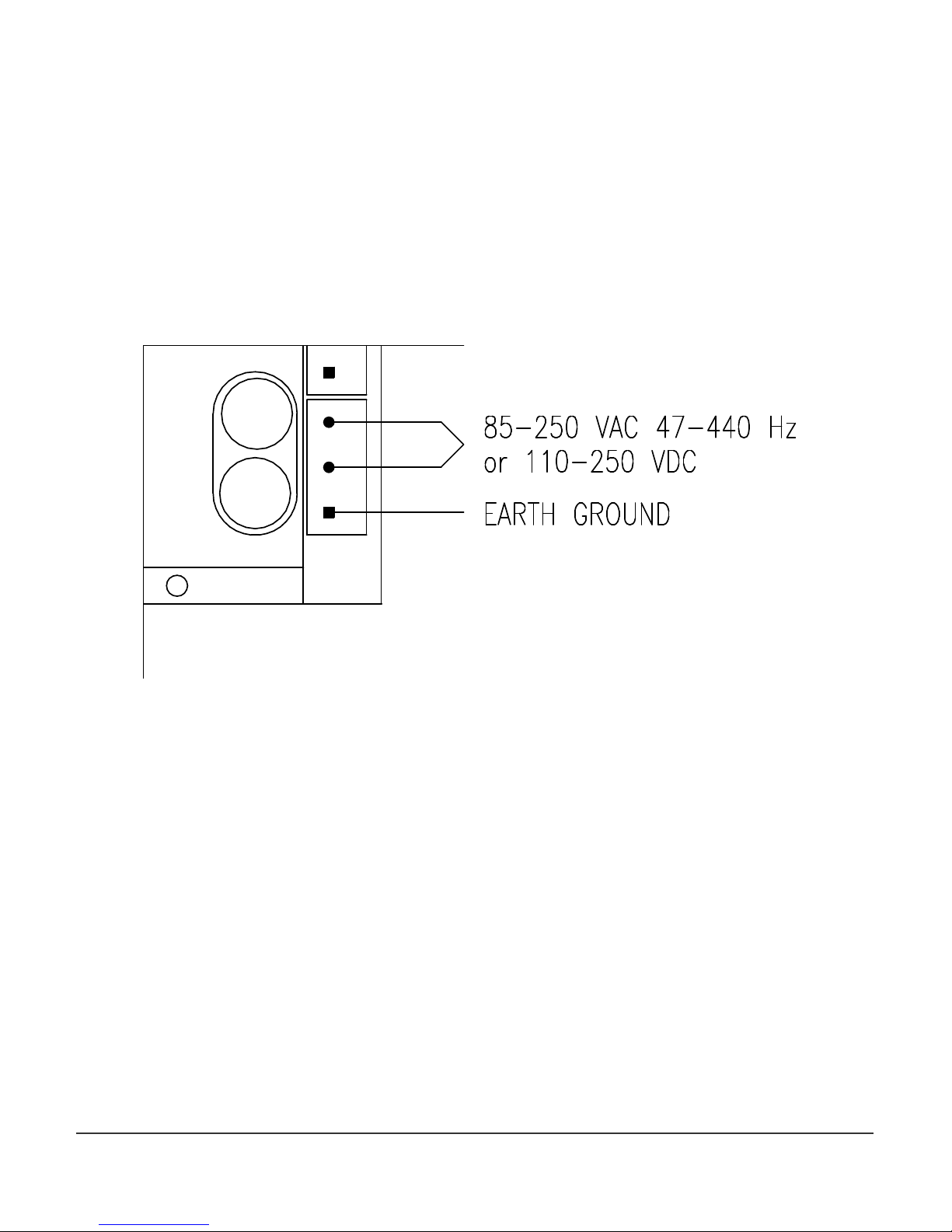
1. Controller Power
The CT224 Power connections will vary depending on which type of power is use.
AC
On AC models, the Line and Neutral will be connected to the terminal block in the lower right
hand corner on the rear of the CT224. See Figure 5. The lower terminal on the terminal block
is used for ground. It is important to connect earth ground to the lower terminal if shielded
cable is used for sensors. This connection is how a grounding connection is made to the
shields of the RTDs. Connecting to earth ground also provides a path for current to flow in
the event of an electrical failure and helps to protect the operator from possible electrocution
in such an event.
Fuse
Fuse
Figure 5 – AC Power Connections
Minco Tel: 763.571.3121 • Fax: 763.571.0927 • www.minco.com 8
Page 9
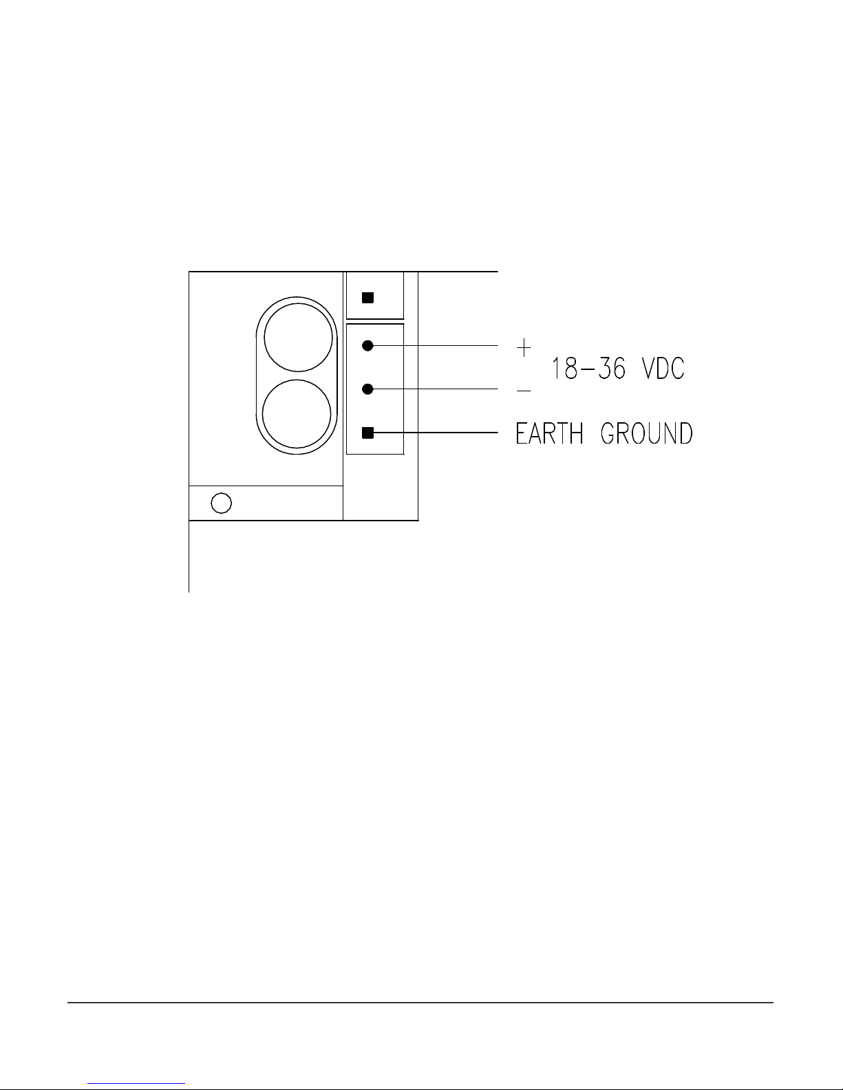
DC
On DC models, the DC voltage is connected to the upper terminals and the terminal block in
the lower right corner on the rear of the CT224. See Figure 6. The upper terminal on the
control power terminal block is connected to the positive supply voltage, between 18 and
36Vdc. The lower terminal on the terminal block is used for ground. It is important to
connect earth ground to the lower terminal if shielded cable is used for sensors. This
connection is how a grounding connection is made to the shields of the RTDs. Connecting to
earth ground also provides a path for current to flow in the event of an electrical failure and
helps to protect the operator from possible electrocution in such an event.
Fuse
Fuse
Figure 6 – DC Power Connections
Minco Tel: 763.571.3121 • Fax: 763.571.0927 • www.minco.com 9
Page 10

2. Inputs
Maximum Length for
The CT224 can accept any combination of the input types specified in Section 6 at the end of
this document. These may include RTDs, thermocouples, and 4-20mA transmitter loops.
However, some care must be taken when using multiple inputs so that a safe environment is
created for personnel and equipment. For instance, a CT224 should monitor sensors from
only one piece of equipment, especially if high voltage is present. Using this approach,
damage to other devices is greatly reduced, if a circuit fault should occur.
The CT224 does not have channel to channel isolation. This means that grounded
thermocouples cannot be used directly with the CT224. Ungrounded thermocouples may be
used. If grounded thermocouples are used, a device such a Thermocouple Isolator can be
utilized as a means to break ground loops and provide proper inputs to the CT224.
Another consideration due to not having channel to channel isolation is that when using 420mA inputs, all loops will share the same return path. Keep this in mind when planning the
system to ensure that it is safe to wire all loops together. It is the system designer’s
responsibility to ensure that good safety measures are used. If unsure about the safety
aspects of a system, call Minco for assistance.
Each input channel has 3 input terminals and a common earth ground terminal. The
terminals are labeled as A, B, C and D. Terminal D is connected to earth ground, when earth
ground is connected to the terminal block as described in Section 1, Controller Power. Input
wiring for the different input types is shown in Figures 7, 8, 9, and 10.
RTDs - RTDs Use three terminals per channel. Care should be taken to not exceed 30 ohms of
lead wire resistance. Chart 1 shows maximum lead wire length per lead of an RTD so as not to
exceed the 30 ohms maximum lead wire resistance. Leadwire for RTDs should be twisted and
shielded, this will reduce fluctuations in the readings due to noise.
3-wire RTD: The odd colored wire must be connected to terminal A of the input channel.
The other two wires can be placed in either order in B and C. If the RTD has a shield, place it
into terminal D. When adding leadwire to the RTD, be sure to use the same length and gauge
for each lead. The CT224 is able to provide very good compensation for leadwire resistance
as long as each lead has the same resistance. Recommended Extension Leadwire: Belden
1031A or any other wire that is twisted and shielded is a good choice.
Leadwire
(AWG)
Ohms/Foot at
25ºC
18 .0065 4615
20 .0103 2912
22 .0165 1818
24 .0262 1145
26 .0418 717
28 .0666 450
30 ohms of
Resistance
Chart 1 – Leadwire Resistance per lead
Minco Tel: 763.571.3121 • Fax: 763.571.0927 • www.minco.com 10
Page 11

Figure 7
– 3-
Wire RTD Wiring
2-wire RTD: One of the leads should be placed in terminal A for the input channel. The
other lead should be placed in either B or C. A jumper wire must be placed between B and C
in order to complete the input circuit. If the RTD has a shield, connect it to terminal D.
Recommended Extension Leadwire: Belden 1030A or any other wire that is twisted and
shielded is a good choice.
The 2-wire RTD will exhibit some error due to the inability to compensate for lead wire
resistance. This can be partially compensated by using the Zone Offset feature as shown later
in the manual under the Programming Configuration section. Chart 2 shows lead wire
resistance based on wire gauge. The desired offset value can be calculated using the chart,
length of leadwire, and by visiting www.minco.com and using the “Sensor Calc” program to
determine the affect of the leadwire. By using this information it is possible to reduce the
leadwire error by adjusting the offset.
Figure 8 – 2-Wire RTD Wiring
Minco Tel: 763.571.3121 • Fax: 763.571.0927 • www.minco.com 11
Page 12
Thermocouples – Thermocouples use terminals B and C. The positive lead on the
thermocouple should be connected to the B terminal and the negative lead to the C terminal.
On a thermocouple the red lead is usually negative (–) and the other lead is usually positive
(+). Figure 9 shows how to wire the Thermocouple to the CT224.
Figure 9 – Thermocouple Wiring
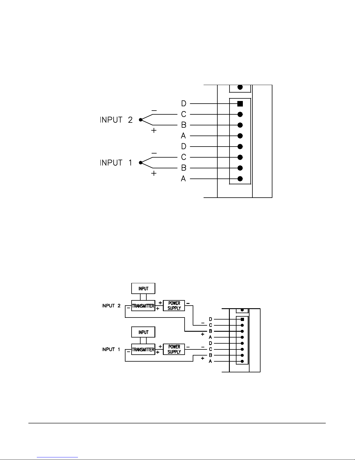
4-20mA – 4-20mA inputs use terminals B and C. The loop positive should be connected to
the B terminal and the loop negative should be connected the C terminal. When configuring
the CT224 for 4-20mA loops, you must set the jumpers located on the top part of the PCB to
the position with out the dot. This is shown in Figure 1 in the Pre-Installation Instruction
section.
Figure 10
– 4-20mA Wiring Diagram
Minco Tel: 763.571.3121 • Fax: 763.571.0927 • www.minco.com 12
Page 13

3. Outputs
Two types of outputs are available on the CT224, relays or logic. The output type is
determined by the options that were ordered.
There are three terminals for each output. All three terminals are used when relays are the
output type. When logic outputs are installed, only two of the terminals are used. The
terminals are labeled as A, B, C. Caution: The terminal positions are A, B, C on the left side of
the unit reading from top to bottom, but they are labeled as C, B, A on the right side of the
unit.
The CT224 has 5 outputs. Four of the outputs are used for signals and can be configured to
trip and untrip in several different ways. The different methods are covered in section
4. Program Configuration part B) Entering The Program Settings. The Alarm Output
differs from the other 4 outputs in several ways. The Alarm Output will use the hysteresis
value for the channel that caused it to trip as it’s untrip value. If the alarm is configured to
sound with a channel that is set to latch another output on a trip, the alarm will continue to
sound until a key is pressed. The Alarm Output cannot be configured for reverse acting, it is
always direct acting.
Relay outputs: Relays are SPDT, they have terminals for both normally open (NO) and
normally closed (NC) contacts. The NO contact is between terminals B and C and the NC
contacts are between terminals A and B.
Logic outputs: Logic outputs use terminals A and B, with B as the reference ground. Logic
outputs are not isolated from the controller supply. Caution must be taken when using logic
outputs since several devices may be sharing the same reference ground when they are
connected.
Minco Tel: 763.571.3121 • Fax: 763.571.0927 • www.minco.com 13
Page 14

4. Serial Communications
Modbus protocol is used to communicate between the CT224 and other device (PC or PLC).
Two physical interface options are available for serial communications. They are RS232 and
RS485. The CT224 is always a slave device.
RS485
RS485 allows for multiple devices to be connected to one network. Up to 128 CT224 can be
connected to a network. The RS485 standard allows up to 32 nodes to be connected on a
half-duplex network. However, each CT224 accounts for only ¼ of a node, so 128 CT224 can
be connected to the network when RS485 is used as the medium.
The connections on the CT224 are labeled as A, B, and S. The two signal wires are A and B.
The A terminal should be connected to the A terminal on the RS232 to RS485 converter. The
B terminal should be connected to the B terminal on the RS232 to RS485 converter. The S
terminal should be connected to the shield. The shield wire should be connected to ground
in one location only, to avoid ground loops, which can cause erratic communications. Refer
to Figure 11 for a wiring diagram.
RS232
Terminal A is the Transmit Data (TD) connection, terminal B is the Receive Data (RD)
connection, and terminal S is the Signal Ground (SG) connection on the CT224. RS232 devices
require Terminal A connected to Receive Data from the master device, Terminal B to Transmit
Data from the master device, and terminal S to Signal Ground. For a 9-pin D-Sub connector
on a PC, connect A to pin2, B to pin 3, and S to pin 5. Caution should be taken when using
RS232, as it is not isolated. This could cause ground loops through devices, which could
cause damage to the CT224 and / or other devices. Refer to Figure 11 for a wiring diagram.
Minco Tel: 763.571.3121 • Fax: 763.571.0927 • www.minco.com 14
Page 15
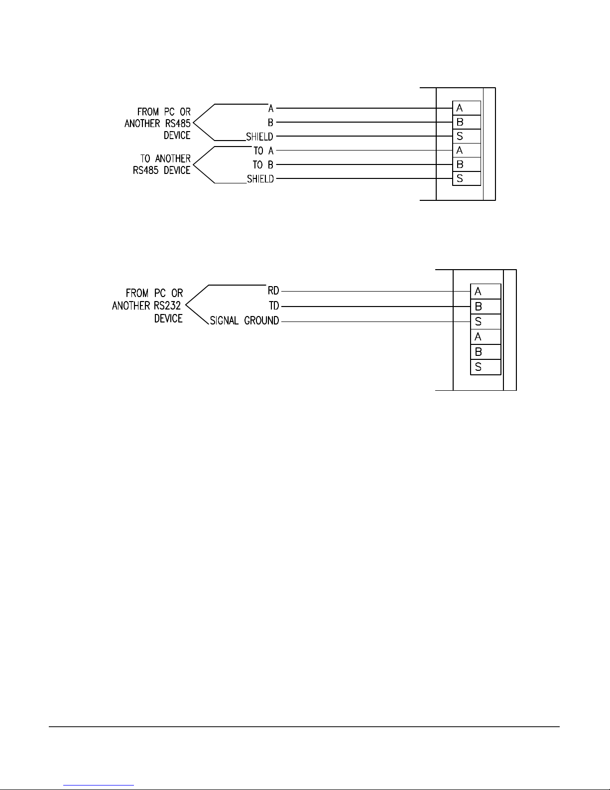
RS485
RS232
Figure 11
– Wiring diagrams for RS232 and RS485
Minco Tel: 763.571.3121 • Fax: 763.571.0927 • www.minco.com 15
Page 16
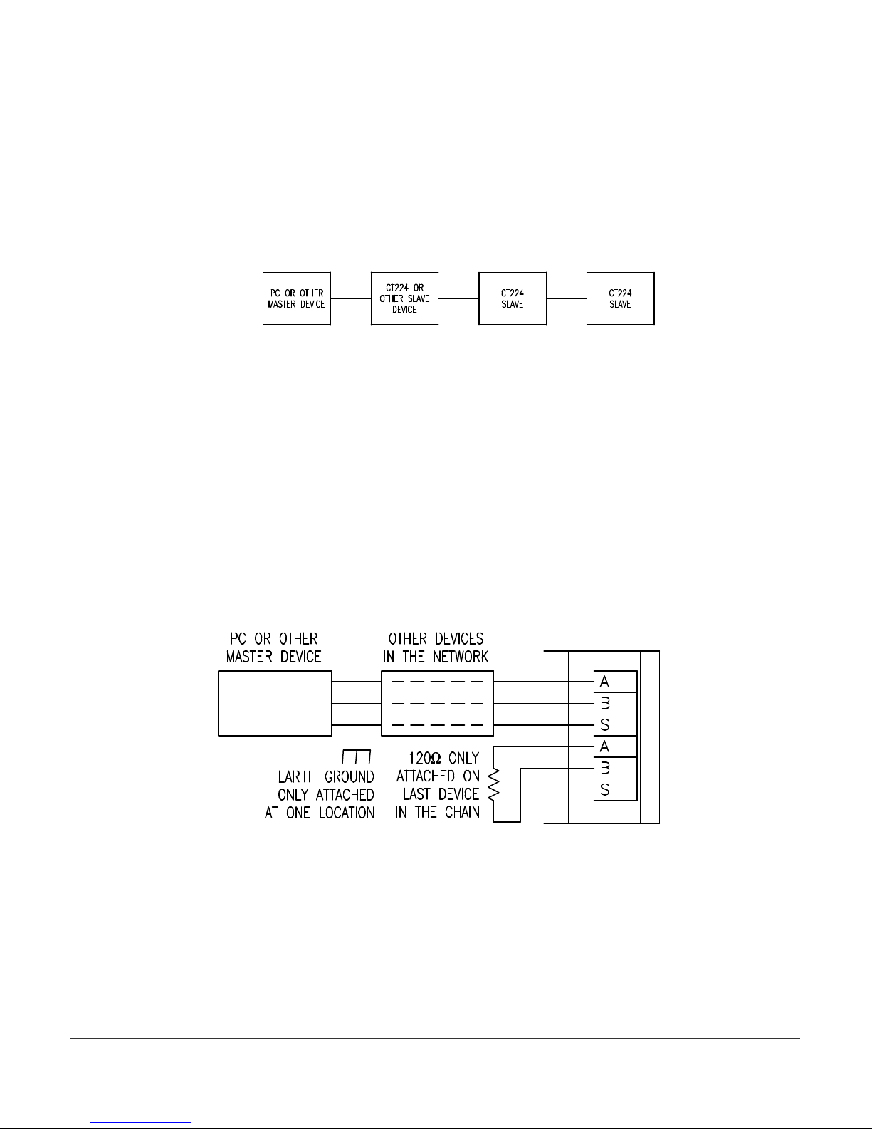
Connecting Multiple CT224
A network of CT224’s should be wired so that the CT224’s are in a chain. However, only
devices using RS485 can be connected in this manner. RS232 will only allow one (1) device to
be connected to a port, so RS232 devices cannot be used in a network. A star or ring
configuration is not appropriate for RS485. Each CT224 should only be connected to at most
2 other CT224. Figure 12 shows the basic wiring for a chain configuration. Like terminals on
the CT224’s should be connected together in the chain, A to A, B to B, S to S.
Figure 12 – Master Slave Chain
End devices (Master and last Slave) on an RS485 network should be terminated to achieve
error-free communications. The termination should match the characteristic impedance of
the network. Normally this value is about 120ohms. Figure 13 shows how to easily apply a
termination resistor to the last CT224 in a chain. Do not use more than 2 termination resistors
on the network. There are many other methods for terminating an RS485 network. If
interested in trying a different termination approach, consult the Internet for various other
configurations. In most applications, terminating with 120ohm resistors will provide errorfree communications.
Figure 13 – Termination of RS485 Network
Minco Tel: 763.571.3121 • Fax: 763.571.0927 • www.minco.com 16
Page 17

4. Program Configuration
A. Using the CT224
The CT224 has two main modes of operation, Monitoring Mode and Menu Mode. When the
CT224 is powered up it will enter Monitoring Mode. Initially the message “Initializing Inputs”
will be shown on the display. The CT224 is evaluating the inputs and initializing the outputs
based on the program configuration that has been stored in the device. After a few seconds
the screen will change and display an input reading.
1. Modes / Buttons
The CT224 has 4 buttons. The user interface has been designed to offer quick modifications
to many parameters in an easy to use manner. Buttons have different purposes depending on
the Mode of the CT224.
Monitoring Mode
Most of the time the unit will be in Monitoring Mode. In Monitoring Mode, all zones
that are configured for input (including the Cold Junction Compensation value), are
scanned and the program settings are used to adjust the outputs.
When in Monitoring Mode, the Back and Right arrow buttons display the next lower
input zone while the Enter and Up arrow buttons move to the next higher input zone.
When customized zone names are used, they will be displayed. The name given to
input zone 1 will be displayed in place of the default name “ZONE 1”. Entering a
custom zone name can be done by entering Menu Mode, selecting Options, Rename
Zones.
Menu Mode
To enter Menu Mode from Monitoring Mode, press and hold any key for 3 seconds. A
beep will sound and the main menu will be shown. There are many different menus
that can be accessed in the Menu Mode. While in Menu Mode, the inputs are not read
and outputs are not adjusted. A 60-second countdown is started each time a key is
pressed when in Menu Mode. If 60 seconds passes without pressing a key, the CT224
will reset and enter Monitoring Mode and continue to evaluate inputs and outputs.
The buttons in Menu Mode are used for different purposes based on which area is
entered. The Back and Right arrow buttons move the cursor up one line and the Enter
and Up arrow move the cursor down one line when making a selection from a list.
When a selection is made which prompts the user for input, then the buttons take on
different tasks. When prompted to enter a value, the Up arrow is used to change the
value of the character or the selection where the cursor is located. Once the desired
character has been set at the current cursor position, pressing the right arrow will
move the cursor to the next position and the Up arrow can be used to adjust that
character. Pressing Enter will accept (and save) the current setting and advance to the
next step in the configuration process. The Back button is used to move back to the
previous step in the configuration process or exit the section that is currently being
Minco Tel: 763.571.3121 • Fax: 763.571.0927 • www.minco.com 17
Page 18

modified. To quickly exit an area where configuration is being done, hold the Enter
Key for 3 seconds and the mode will be exited. All parameters that were modified and
saved by pressing Enter will be saved.
The first menu shown when Menu Mode is entered is the Main Menu. It allows the
following choices:
1. Monitor Zones
2. Setup
3. Manual Reset
4. Options
1. Monitor Zones
Select this option to return to Monitoring Mode to read and evaluate the inputs and
outputs.
2. Setup Menu
The Configuration Menu may require a password to enter, by default no password is
required. The Configuration Menu contains the following options.
1. Change Passwords
2. Change Settings
3. Modify Offsets
4. Comm Settings
1. Change Passwords - Select the password to change. A message asking
if you would like to change a password will be shown. Choose ‘Yes’ to change a
password or ‘No’ to exit the Change Passwords option. By setting a password
to 0000, the password will be deactivated. The valid range for a password is
0000 to 9999. If a password is already entered, the user will be required to
enter the existing password in order to change it. If you forget your password,
the master password can be used, it is found on the last page of this manual.
Available selections are:
1. Program Password
2. Unlatch Password
1. Program Password – Changes the password that is used to
protect the Change Program option.
2. Unlatch Password – Changes the password that is used to
protect Manual Reset of the Outputs.
2. Change Settings - This section is used to configure all inputs and
outputs. (May be password protected.) When this section is exited, either due
to the 60-second timeout or exited by the user, the CT224 will automatically
reset and start scanning with the new program settings. The CT224 will also
reset when program settings are changed via the communications link using
MincoSoft’s CT224 Software. This is the main section of the CT224
configuration process and has a full section below covering its use. See section
4B, Entering the Program Settings, for more information.
Minco Tel: 763.571.3121 • Fax: 763.571.0927 • www.minco.com 18
Page 19

3. Modify Offsets - Adjust the offset for each input zone. The offsets are
used to improve accuracy of the readings. This could be useful if a 2-wire RTD
is used or a particular value is crucial in a process. The offset can be used so
that less error is present. The units for the offset are Tenths. So, if the reading
is off by -1 degree (or 1 unit in any other measurement), the number that
should be entered for the offset value is 10, because this will raise the value by
10 tenths or +1 degree.
4. Comm Settings – This selection steps through setting the monitor
address and the baud rate for the serial communications. The settings chosen
must match the settings selected by the master device that will be
communicating with the CT224. The first screen requests the user to enter the
Modbus address. The valid range of addresses is from 1 to 247. If 0 is selected,
the CT224 will not monitor the communication lines. Each CT224 is factory set
to a default Modbus address of 1. If communications are not used, it is
acceptable to leave the default address at 1. If multiple CT224 are to be used,
the addresses should be changed to prevent communication errors. The next
screen will request setting the baud rate. Valid baud rates are: 600, 1200, 2400,
4800, 9600, and 19200.
3. Manual Reset - Use this option to reset the outputs if a trip has occurred and
Manual Reset Only was selected when configuring the outputs. (May be password
protected.)
4. Options – Options Menu allows the user to personalize the zone names and
exercise the relays.
1. Rename Zones
2. Exercise Relays
3. Freeze Outputs
1. Rename Zones – This option is used to personalize the display. Up to
16 characters can be entered to describe the input location. Capital letters (AZ), numbers (0-9), and spaces are allowed.
2. Exercise Relays – This option can be used to trip the outputs for test
purposes. This can be helpful to verify that wiring is correct and that
connections are secure. When selected and relays are in tripped condition, the
unit will keep the outputs tripped until another key is pressed.
3. Freeze Outputs – Selecting this option will disable the program from
changing the state of any output. The message “Outputs are Frozen” is
displayed on the screen when this selection is active and the CT224 is in
Monitor Mode. To unfreeze the outputs, choose this option again and the
Freeze Outputs option will be disabled.
Minco Tel: 763.571.3121 • Fax: 763.571.0927 • www.minco.com 19
Page 20

B) Entering the Program Settings
The first step to take when configuring the CT224 is to decide how you would like the device
configured. Configuration is best performed using MincoSoft CT224 Software. If you do not
have a computer available for configuration you may also use the keypad on the CT224 to
enter the settings. If using the keypad to configure the CT224, use the Setup Worksheet to
speed up the process and reduce errors. Due to the 60-second timeout in the CT224, it is best
to fill out the Setup Worksheet before configuring the unit. This will also allow you to have
record of the settings that are programmed into the unit for future reference.
A description for each of the configuration options is give on the following pages.
Reverse acting outputs? - Choose the outputs you would like to configure for reverse action.
N – Relay: Normally Open (NO) contact will be open and the Normally Closed (NC)
contact will be closed.
Logic: Output will be low (0V) in untripped state.
Y – Relay: NO contact will be closed and the NC contact will be open in the untripped
state. The Logic: Output will be high (+5V) in untripped state.
Temperature Scale: Choose the temperature scale that the CT224 should use. RTDs and
thermocouples will use this temperature scale for display. Options are F, Fahrenheit and C,
Celsius.
Zone to be displayed during normal operation: Choose how the input readings should be
displayed.
The user can always adjust the displayed reading by pressing keys, after 5 seconds the CT224
will resume it’s process of displaying the High, Low or Scanning through inputs.
High – Highest input reading is displayed, regardless of input type.
Low – Lowest input reading is displayed, regardless of input type.
Any – Display will stay on the zone that the user has set it to.
Minutes of alarm silence when a key is pressed: Set the amount of time to wait until the
alarm will resound, if the alarm condition is still present. Valid range is 1 to 100 minutes or
Stays Off. This setting only resounds the alarm, it will not re-trip an output. It is designed to
remind personnel that there is still a trip condition in affect.
If an input fails: This setting allows the user to determine what action the CT224
should take if a broken sensor is detected.
Sound alarm – Alarm will sound if input fails. Alarm will resound according to the
“Minutes of alarm silence when a key is pressed” set in the previous step.
Trip output(s) associated with failed input – All outputs configured to trip on the
channel that has a failed input will trip.
Ignore – Continue operating like the input is still functioning properly.
Minco Tel: 763.571.3121 • Fax: 763.571.0927 • www.minco.com 20
Page 21

Choose input type: Select the input type for this zone. Options are:
Resistance
Type
Sensor Range
RTD Inputs
Material
at 0ºC in ohms
TCR
Sensor Range
Platinum (PA) 100 .00392 -200 to 700ºC (-328 to 1292ºF)
Platinum (PB) 100 .00391 -200 to 700ºC (-328 to 1292ºF)
Platinum (PD or PE)
100 .00385 -200 to 850ºC (-328 to 1562ºF)
Platinum (PF) 1000 .00385 -200 to 600ºC (-328 to 1112ºF)
Nickel (NA) 120 .00672 -80 to 260ºC (-112 to 500ºF)
Copper (CA)
9.035 (10 Ω at 25°C)
.00427 -100 to 260ºC (-148 to 500ºF)
Thermocouple Inputs
E -270 to 1000ºC (-454 to 1832ºF)
J -200 to 1200ºC (-328 to 2192ºF)
K -270 to 1150ºC (-454 to 2102ºF)
T -270 to 400ºC (-454 to 752ºF)
4-20mA Transmitters: Output proportional to process variable for Pressure PSI, Pressure Bar,
% Relative Humidity, Process Variable mA, Process Variable Vdc, Vibration G, Temperature ºC,
Temperature ºF.
Enter Low End of Transmitter Range: This setting will only be displayed if a 4-20mA input is
selected in the previous step. All ranges for RTDs and thermocouples are fixed. The valid
input range is between -999 and 9999.
Enter High End of Transmitter Range: This setting is also only available when a 4-20mA
input is selected. The valid input range is between –999 and 9999. The high end of the
transmitter range must be higher than the low end.
Zone X Trip 1: Set the trip value for this zone. When Trip 2 is displayed it will correspond to
the second trip value for the zone. Valid temperature ranges are shown in the charts found
under “Choose input type:”. If a value not within the range for the sensor is entered, a
warning will be displayed and a new, valid setting should be entered.
Trip Over or Under? – This setting determines when the outputs will trip.
Over – Outputs for the zone will trip when the reading is higher than the trip value.
Under – Outputs for the zone will trip when the reading is lower than the trip value.
Sound Alarm on Trip? –Yes will cause the alarm to sound and alarm output to trip when the
reading passes the trip value. Selecting No will not sound the alarm when the outputs are
tripped.
Minco Tel: 763.571.3121 • Fax: 763.571.0927 • www.minco.com 21
Page 22

Outputs to trip:
Output1__ Output2__
Output3__ Output4__ - A Y after the output indicates to trip the output when the reading
passed the trip value. An N after the output indicates the output should not be tripped.
Untrip Outputs by: - This setting will determine how the outputs associated with this trip will
be untripped.
Manual Reset Only – This setting causes the outputs to latch. In addition,
temperature display will show highest reading since the trip event. The outputs can
only be reset by entering the Main Menu and selecting Manual Reset. This will also
return temperature display to normal operation. (A password may be necessary to
reset the relays.)
Pressing Enter – The outputs will untrip when Enter is pressed.
Using Hysteresis – The outputs will untrip when the input value exits the hysteresis
(deadband) limit.
Note: The order of precedence for the methods of untrip is Manual Reset Only,
Pressing Enter, and then Using Hysteresis. This means that if at any time an output is
tripped and configured by an zone to untrip using Manual Reset Only, the only way to
untrip that zone is using the Manual Reset.
Note: When any zone causes a trip for an output, all zones that have caused a trip on
that output will be refreshed. This means that if an output has been tripped and then
cleared by pressing Enter and another zone causes that output to retrip, the output
will act as though both trips have reoccurred at the same time to cause the output to
trip. So, if the second trip were to reset by dropping below the programmed
hysteresis value, the output will still be tripped, due to the first zone, which caused the
trip. To reset the output again, Enter would need to be pressed.
Set Hysteresis: - Hysteresis is the amount that the reading must move past the trip value
before the outputs will reset. For example, the system is configured to trip at 100ºF, has a
10ºF hysteresis and will trip Output 1 on an over temperature reading. The reading increases
to 100ºF, so Output 1 trips. The reading will need to go below 90ºF before Output 1 will reset.
Minco Tel: 763.571.3121 • Fax: 763.571.0927 • www.minco.com 22
Page 23

C. Setup Worksheet
Prompt
Description
Selection
Reverse acting
Choose which outputs should be
Output 1
__ Output 2__
Temperature Scale:
Choose the temperature scale to
Degrees _____
Zone t
o be
Choose how input readings
High
Minutes of alarm
Set the amount of time that
________
Minutes
If an input fails:
Choose action to take if input fails.
Sound Alarm
Zone X Trip 1:
Choose the type of input that is
Zone 1 _____ Zone 6_____
Zone X Trip 1:
For 4
-
20mA current loops, enter
Zone 1 ____
_ Zone 6_____
outputs?
displayed during
normal operation:
silence when a key
is pressed:
Choose input type:
in an active state, before a trip
condition occurs.
which the CT224 should be
configured.
should be displayed.
should pass before the alarm will
resound due to an alarm
condition.
attached.
Output 3__ Output 4__
Low
Any
Trip Output(s)
Ignore
Zone 2 _____ Zone 7_____
Zone 3 _____ Zone 8_____
Zone 4 _____ Zone 9_____
Zone 5 _____ Zone 10_____
Zone 6 _____ Zone 11_____
Zone 7 _____ Zone 12_____
Enter Low End of
Transmitter Range:
Minco Tel: 763.571.3121 • Fax: 763.571.0927 • www.minco.com 23
the low end of the range of the
input. These settings will not be
used for RTD and Thermocouple
inputs. The range for RTD and
Thermocouples are not
changeable. See Specifications in
the rear of the manual for the
range of RTD and Thermocouples.
Zone 2 _____ Zone 7_____
Zone 3 _____ Zone 8_____
Zone 4 _____ Zone 9_____
Zone 5 _____ Zone 10_____
Zone 6 _____ Zone 11_____
Zone 7 _____ Zone 12_____
Page 24

Prompt
Description
Selection
Zone X Trip 1:
Enter High End of
For 4
-
20mA current loops, enter
Zone 1 _____ Zone 6_____
Zone X Trip 1:
Set the trip value.
Zone X Trip 1:
Set the input condition for when
Zone 1 _____ Zone 6_____
Zone X Trip 1:
Set to alarm when an output is
Zone 1 _____ Zone 6_____
Transmitter Range:
the high end of the range of the
input.
Zone 2 _____ Zone 7_____
Zone 3 _____ Zone 8_____
Zone 4 _____ Zone 9_____
Zone 5 _____ Zone 10_____
Zone 6 _____ Zone 11_____
Zone 7 _____ Zone 12_____
Zone 1 _____ Zone 6_____
Zone 2 _____ Zone 7_____
Zone 3 _____ Zone 8_____
Zone 4 _____ Zone 9_____
Zone 5 _____ Zone 10_____
Zone 6 _____ Zone 11_____
Zone 7 _____ Zone 12_____
Trip Over or Under?
Sound Alarm on
Trip?
the output(s) should trip.
tripped.
Zone 2 _____ Zone 7_____
Zone 3 _____ Zone 8_____
Zone 4 _____ Zone 9_____
Zone 5 _____ Zone 10_____
Zone 6 _____ Zone 11_____
Zone 7 _____ Zone 12_____
Zone 2 _____ Zone 7_____
Zone 3 _____ Zone 8_____
Zone 4 _____ Zone 9_____
Zone 5 _____ Zone 10_____
Zone 6 _____ Zone 11_____
Zone 7 _____ Zone 12_____
Minco Tel: 763.571.3121 • Fax: 763.571.0927 • www.minco.com 24
Page 25

Prompt
Description
Selection
Zone X T
rip 1:
Outputs to trip:
Choose outputs to trip when trip
Zone 1 Trip 1: Zone 7 Trip 1:
Zone X Trip 1:
Choose the preferred method
to
Zone 1 _____ Zone 6_____
Zone X Trip 1:
Set the hysteresis (deadband)
Zone 1 _____ Zone 6_____
Output1__
Output2__
Output3__
Output4__
value is observed.
Output1__ Output2__ Output1__ Output2__
Output3__ Output4__ Output3__ Output4__
Zone 2 Trip 1: Zone 8 Trip 1:
Output1__ Output2__ Output1__ Output2__
Output3__ Output4__ Output3__ Output4__
Zone 3 Trip 1: Zone 9 Trip 1:
Output1__ Output2__ Output1__ Output2__
Output3__ Output4__ Output3__ Output4__
Zone 4 Trip 1: Zone 10 Trip 1:
Output1__ Output2__ Output1__ Output2__
Output3__ Output4__ Output3__ Output4__
Zone 5 Trip 1: Zone 11 Trip 1:
Output1__ Output2__ Output1__ Output2__
Output3__ Output4__ Output3__ Output4__
Zone 6 Trip 1: Zone 12 Trip 1:
Output1__ Output2__ Output1__ Output2__
Output3__ Output4__ Output3__ Output4__
Untrip Outputs by:
Set Hysteresis:
untrip the outputs.
value. Hysteresis is the amount
that the input value must pass
beyond the trip value before the
output will untrip.
Zone 2 _____ Zone 7_____
Zone 3 _____ Zone 8_____
Zone 4 _____ Zone 9_____
Zone 5 _____ Zone 10_____
Zone 6 _____ Zone 11_____
Zone 7 _____ Zone 12_____
Zone 2 _____ Zone 7_____
Zone 3 _____ Zone 8_____
Zone 4 _____ Zone 9_____
Zone 5 _____ Zone 10_____
Zone 6 _____ Zone 11_____
Zone 7 _____ Zone 12_____
Minco Tel: 763.571.3121 • Fax: 763.571.0927 • www.minco.com 25
Page 26

Prompt
Description
Selection
Zone X Trip 2:
Choose input type:
Choose the type of input that is
Zone
1 _____ Zone 6_____
Zone X Trip 2:
Enter the low end of the range of
Zone 1 _____ Zone 6_____
Zone X Trip 2:
Enter the high end of the range of
Zone 1 _____ Zone 6_____
Zone X Trip 2:
Set the trip value.
Zone 1 _____ Zone 6_____
attached.
Zone 2 _____ Zone 7_____
Zone 3 _____ Zone 8_____
Zone 4 _____ Zone 9_____
Zone 5 _____ Zone 10_____
Zone 6 _____ Zone 11_____
Zone 7 _____ Zone 12_____
Enter Low End of
Transmitter Range:
(4-20mA inputs
only, if another
input type is
selected, this option
will not be
displayed.)
Enter High End of
Transmitter Range:
(4-20mA inputs
only, if another
input type is
selected, this option
will not be
displayed.)
the input.
the input.
Zone 2 _____ Zone 7_____
Zone 3 _____ Zone 8_____
Zone 4 _____ Zone 9_____
Zone 5 _____ Zone 10_____
Zone 6 _____ Zone 11_____
Zone 7 _____ Zone 12_____
Zone 2 _____ Zone 7_____
Zone 3 _____ Zone 8_____
Zone 4 _____ Zone 9_____
Zone 5 _____ Zone 10_____
Zone 6 _____ Zone 11_____
Zone 7 _____ Zone 12_____
Minco Tel: 763.571.3121 • Fax: 763.571.0927 • www.minco.com 26
Zone 2 _____ Zone 7_____
Zone 3 _____ Zone 8_____
Zone 4 _____ Zone 9_____
Zone 5 _____ Zone 10_____
Zone 6 _____ Zone 11_____
Zone 7 _____ Zone 12_____
Page 27

Prompt
Description
Selection
Zone X Trip 2:
Trip Over or Under?
Set the condition when the
Zone 1 _____ Zone 6_____
Zone X Trip 2:
Set to alarm when an output is
Zone 1 _____
Zone 6_____
Zone X Trip 2:
Choose outputs to trip when trip
Zone 1 Trip 1: Zone 7 Trip 1:
outputs should trip.
Zone 2 _____ Zone 7_____
Zone 3 _____ Zone 8_____
Zone 4 _____ Zone 9_____
Zone 5 _____ Zone 10_____
Zone 6 _____ Zone 11_____
Zone 7 _____ Zone 12_____
Sound Alarm on
Trip?
Outputs to trip:
Output1__
Output2__
Output3__
Output4__
tripped.
value is observed.
Zone 2 _____ Zone 7_____
Zone 3 _____ Zone 8_____
Zone 4 _____ Zone 9_____
Zone 5 _____ Zone 10_____
Zone 6 _____ Zone 11_____
Zone 7 _____ Zone 12_____
Output1__ Output2__ Output1__ Output2__
Output3__ Output4__ Output3__ Output4__
Zone 2 Trip 1: Zone 8 Trip 1:
Output1__ Output2__ Output1__ Output2__
Output3__ Output4__ Output3__ Output4__
Zone 3 Trip 1: Zone 9 Trip 1:
Output1__ Output2__ Output1__ Output2__
Output3__ Output4__ Output3__ Output4__
Zone 4 Trip 1: Zone 10 Trip 1:
Output1__ Output2__ Output1__ Output2__
Output3__ Output4__ Output3__ Output4__
Zone 5 Trip 1: Zone 11 Trip 1:
Output1__ Output2__ Output1__ Output2__
Output3__ Output4__ Output3__ Output4__
Zone 6 Trip 1: Zone 12 Trip 1:
Output1__ Output2__ Output1__ Output2__
Output3__ Output4__ Output3__ Output4__
Minco Tel: 763.571.3121 • Fax: 763.571.0927 • www.minco.com 27
Page 28

Zone X Trip 2:
Choose the preferred method to
Zone 1 _____ Zone 6_____
Zone X
Trip 2:
Set the hysteresis (deadband)
Zone 1 _____ Zone 6_____
Untrip Outputs by:
Set Hysteresis:
untrip the outputs.
value. Hysteresis is the amount
that the input value must pass
beyond the trip value before the
output will untrip.
Zone 2 _____ Zone 7_____
Zone 3 _____ Zone 8_____
Zone 4 _____ Zone 9_____
Zone 5 _____ Zone 10_____
Zone 6 _____ Zone 11_____
Zone 7 _____ Zone 12_____
Zone 2 _____ Zone 7_____
Zone 3 _____ Zone 8_____
Zone 4 _____ Zone 9_____
Zone 5 _____ Zone 10_____
Zone 6 _____ Zone 11_____
Zone 7 _____ Zone 12_____
Minco Tel: 763.571.3121 • Fax: 763.571.0927 • www.minco.com 28
Page 29

5. Communications
The CT224 uses Modbus protocol to communicate over an RS485 bus. RTU transmission
mode is supported by the CT224. ASCII transmission mode is not supported. Data transfer
must adhere to the following data format: 1 start bit, 8 data bits and 1 stop bit. Supported
data rates are: 600, 1200, 2400, 4800, 9600, and 19200 baud. Supported function codes are
0x03, 0x04, and 0x10. These instructions allow the program settings to be read and modified
and access to the input readings on the monitor. The communications are limited to 41
characters per transmission, including header information and checksum. A character is
defined as hexadecimal 0 … 9, A … F. Modbus addresses are allowed in the range from 1 to
247. If the CT224 is set to a Modbus address of 0, the unit will ignore all signals on the
communication inputs.
The CT224 supports half-duplex operation. This means that only two signal wires are required
to send and receive signals. Using half-duplex operation helps to minimize wiring and still
provides the long distance communications allowed while using RS485. Wire lengths up to
4000 ft. are allowed with RS485 as compared to only 50 ft. using RS232.
Using a PC for RS485 Communications
Minco offers an accessory package (AC102734) that contains an isolated RS232 to RS485
converter, power supply to power the converter, and a DB25 to DB9 adapter. These parts
have been thoroughly tested and have been found to work properly with the CT224 and
MincoSoft CT224 software. MincoSoft CT224 software is configured to use a converter that
requires DTR to be active all of the time and RTS to be active when transmitting and inactive
when receiving. Other converters that have the same requirements will work with the
MincoSoft CT224 software. More information about CT224 Communications can be found in
the MincoSoft CT224 Software Manual. Minco does not guarantee that any other RS232 to
RS485 converter will work with the CT224.
Minco Tel: 763.571.3121 • Fax: 763.571.0927 • www.minco.com 29
Page 30

A) Function Codes
Function Code 0x03 – Read program settings
The 0x03 function code is used to read the program settings in the CT224. Program settings
are shown in the memory map later in this section. The maximum number of data bytes that
can be sent from the CT224 is 32. This is due to the 41 byte limit set for communications.
Therefore, the maximum value that can be used as the number of memory locations to read is
16.
To request data from 3 memory locations starting at location 0x20, the proper data string to
use, assuming the monitor address is 1, would be:
0103002000030104
01 Monitor Address
03 Function Code
00 High byte of starting memory location
20 Low byte of starting memory location
00 High byte of the number of memory locations to read
03 Low byte of the number of memory locations to read
0104 The checksum for the string that is being sent
The response from the CT224 would look like the following:
01030600010002000374FD
01 Monitor Address
03 Function Code
06 Number of data bytes returned
000100020003 Data bytes returned starting at memory location 0x20
74FD The checksum for the string that was sent
Minco Tel: 763.571.3121 • Fax: 763.571.0927 • www.minco.com 30
Page 31

Function Code 0x04 – Read current inputs
The 0x04 function code is used to retrieve the current input readings.
To request data from 4 memory locations starting at location 0x10, the proper data string to
use, assuming the monitor address is 1, would be:
010400100003CEB1
01 Monitor Address
04 Function Code
00 High byte of starting memory location
10 Low byte of starting memory location
00 High byte of the number of memory locations to read
04 Low byte of the number of memory locations to read
0CF0 The checksum for the string that was sent
The response from the CT224 would look something like the following: (Returned data bytes
will obviously vary, depending on the values at those locations.)
0104060001000200030004AEF0
01 Monitor Address
04 Function Code
06 Number of data bytes returned
0001000200030004 Data returned, 4 – 16 bit words
AEF0 The checksum for the string that was sent
Minco Tel: 763.571.3121 • Fax: 763.571.0927 • www.minco.com 31
Page 32

Function Code 0x10 – Write program settings
The 0x10 function code is used to write program settings to the CT224. When sending the
Write Program Settings command, the hexadecimal number 10 will be used. Program
settings are shown in the memory map later in this section. The maximum number of data
bytes that can be sent to the CT224 is 32. This is due to the 41 byte limit set for
communications. Therefore, the maximum value that can be used as the number of memory
locations to write is 16.
To store settings to 3 memory locations starting at location 0x20, the proper data string to
use, assuming the monitor address is 1, would be:
011000200003AABBCCDDEEFF5B39
01 Monitor Address
10 Function Code
00 High byte of starting memory location
20 Low byte of starting memory location
00 High byte of the number of memory locations to write
03 Low byte of the number of memory locations to write
AABB First word of data to send
CCDD Second word of data to send
EEFF Third word of data to send
5B39 The checksum for the string that was sent
The response from the CT224 would look something like the following:
011006C2AD
01 Monitor Address
10 Function Code
06 Number of data bytes received
C2AD The checksum for the string that was sent
Minco Tel: 763.571.3121 • Fax: 763.571.0927 • www.minco.com 32
Page 33

B) Memory Map
Explanation of the Value Format can be found after the chart Current Values for Inputs and
Outputs.
Program Settings are stored according to the chart below:
Register Address Description Value Format
0000 Reverse Acting Relays / Temperature Scale A
0001 Zone to be displayed B
0002 Length of Silence C
0003 Action to take on failed input D
0004 Zone 1 Trip 1 – Input Type E
0005 - Low end of input range F
0006 - High end of input range G
0007 - Trip Value H
0008 - Trip Over or Under I
0009 - Sound Alarm / Outputs to trip J
000A - Output Reset / Hysteresis Value K
000B Zone 1 Trip 2 – Trip Value H
000C - Trip Over or Under I
000D - Sound Alarm / Outputs to trip J
000E - Output Reset / Hysteresis Value K
000F Zone 2 Trip 1 – Input Type E
0010 - Low end of input range F
0011 - High end of input range G
0012 - Trip Value H
0013 - Trip Over or Under I
0014 - Sound Alarm / Outputs to trip J
0015 - Output Reset / Hysteresis Value K
0016 Zone 2 Trip 2 – Trip Value H
0017 - Trip Over or Under I
0018 - Sound Alarm / Outputs to trip J
0019 - Output Reset / Hysteresis Value K
001A Zone 3 Trip 1 – Input Type E
001B - Low end of input range F
001C - High end of input range G
001D - Trip Value H
001E - Trip Over or Under I
001F - Sound Alarm / Outputs to trip J
0020 - Output Reset / Hysteresis Value K
Minco Tel: 763.571.3121 • Fax: 763.571.0927 • www.minco.com 33
Page 34

0021 Zone 3 Trip 2 – Trip Value H
0022 - Trip Over or Under I
0023 - Sound Alarm / Outputs to trip J
0024 - Output Reset / Hysteresis Value K
0025 Zone 4 Trip 1 – Input Type E
0026 - Low end of input range F
0027 - High end of input range G
0028 - Trip Value H
0029 - Trip Over or Under I
002A - Sound Alarm / Outputs to trip J
002B - Output Reset / Hysteresis Value K
002C Zone 4 Trip 2 – Trip Value H
002D - Trip Over or Under I
002E - Sound Alarm / Outputs to trip J
002F - Output Reset / Hysteresis Value K
0030 Zone 5 Trip 1 – Input Type E
0031 - Low end of input range F
0032 - High end of input range G
0033 - Trip Value H
0034 - Trip Over or Under I
0035 - Sound Alarm / Outputs to trip J
0036 - Output Reset / Hysteresis Value K
0037 Zone 5 Trip 2 – Trip Value H
0038 - Trip Over or Under I
0039 - Sound Alarm / Outputs to trip J
003A - Output Reset / Hysteresis Value K
003B Zone 6 Trip 1 – Input Type E
003C - Low end of input range F
003D - High end of input range G
003E - Trip Value H
003F - Trip Over or Under I
0040 - Sound Alarm / Outputs to trip J
0041 - Output Reset / Hysteresis Value K
0042 Zone 6 Trip 2 – Trip Value H
0043 - Trip Over or Under I
0044 - Sound Alarm / Outputs to trip J
0045 - Output Reset / Hysteresis Value K
0046 Zone 7 Trip 1 – Input Type E
Minco Tel: 763.571.3121 • Fax: 763.571.0927 • www.minco.com 34
Page 35

0047 - Low end of input range F
0048 - High end of input range G
0049 - Trip Value H
004A - Trip Over or Under I
004B - Sound Alarm / Outputs to trip J
004C - Output Reset / Hysteresis Value K
004D Zone 7 Trip 2 – Trip Value H
004E - Trip Over or Under I
004F - Sound Alarm / Outputs to trip J
0050 - Output Reset / Hysteresis Value K
0051 Zone 8 Trip 1 – Input Type E
0052 - Low end of input range F
0053 - High end of input range G
0054 - Trip Value H
0055 - Trip Over or Under I
0056 - Sound Alarm / Outputs to trip J
0057 - Output Reset / Hysteresis Value K
0058 Zone 8 Trip 2 – Trip Value H
0059 - Trip Over or Under I
005A - Sound Alarm / Outputs to trip J
005B - Output Reset / Hysteresis Value K
005C Zone 9 Trip 1 – Input Type E
005D - Low end of input range F
005E - High end of input range G
005F - Trip Value H
0060 - Trip Over or Under I
0061 - Sound Alarm / Outputs to trip J
0062 - Output Reset / Hysteresis Value K
0063 Zone 9 Trip 2 – Trip Value H
0064 - Trip Over or Under I
0065 - Sound Alarm / Outputs to trip J
0066 - Output Reset / Hysteresis Value K
0067 Zone 10 Trip 1 – Input Type E
0068 - Low end of input range F
0069 - High end of input range G
006A - Trip Value H
006B - Trip Over or Under I
006C - Sound Alarm / Outputs to trip J
006D - Output Reset / Hysteresis Value K
Minco Tel: 763.571.3121 • Fax: 763.571.0927 • www.minco.com 35
Page 36

006E Zone 10 Trip 2 – Trip Value H
006F - Trip Over or Under I
0070 - Sound Alarm / Outputs to trip J
0071 - Output Reset / Hysteresis Value K
0072 Zone 11 Trip 1 – Input Type E
0073 - Low end of input range F
0074 - High end of input range G
0075 - Trip Value H
0076 - Trip Over or Under I
0077 - Sound Alarm / Outputs to trip J
0078 - Output Reset / Hysteresis Value K
0079 Zone 11 Trip 2 – Trip Value H
007A - Trip Over or Under I
007B - Sound Alarm / Outputs to trip J
007C - Output Reset / Hysteresis Value K
007D Zone 12 Trip 1 – Input Type E
007E - Low end of input range F
007F - High end of input range G
0080 - Trip Value H
0081 - Trip Over or Under I
0082 - Sound Alarm / Outputs to trip J
0083 - Output Reset / Hysteresis Value K
0084 Zone 12 Trip 2 – Trip Value H
0085 - Trip Over or Under I
0086 - Sound Alarm / Outputs to trip J
0087 - Output Reset / Hysteresis Value K
0088 Input Offset – Zone 1 L
0089 - Zone 2 L
008A - Zone 3 L
008B - Zone 4 L
008C - Zone 5 L
008D - Zone 6 L
008E - Zone 7 L
008F - Zone 8 L
0090 - Zone 9 L
0091 - Zone 10 L
0092 - Zone 11 L
0093 - Zone 12 L
0094 Reserved
Minco Tel: 763.571.3121 • Fax: 763.571.0927 • www.minco.com 36
Page 37

0095 Reserved
0096 Reserved
0097 Reserved
0098 Zone 1 Name - Characters 1, 2 M
0099 - Characters 3, 4 M
009A - Characters 5, 6 M
009B - Characters 7, 8 M
009C - Characters 9, 10 M
009D - Characters 11, 12 M
009E - Characters 13, 14 M
009F - Characters 15, 16 M
00A0 Zone 2 Name - Characters 1, 2 M
00A1 - Characters 3, 4 M
00A2 - Characters 5, 6 M
00A3 - Characters 7, 8 M
00A4 - Characters 9, 10 M
00A5 - Characters 11, 12 M
00A6 - Characters 13, 14 M
00A7 - Characters 15, 16 M
00A8 Zone 3 Name - Characters 1, 2 M
00A9 - Characters 3, 4 M
00AA - Characters 5, 6 M
00AB - Characters 7, 8 M
00AC - Characters 9, 10 M
00AD - Characters 11, 12 M
00AE - Characters 13, 14 M
00AF - Characters 15, 16 M
00B0 Zone 4 Name - Characters 1, 2 M
00B1 - Characters 3, 4 M
00B2 - Characters 5, 6 M
00B3 - Characters 7, 8 M
00B4 - Characters 9, 10 M
00B5 - Characters 11, 12 M
00B6 - Characters 13, 14 M
00B7 - Characters 15, 16 M
00B8 Zone 5 Name - Characters 1, 2 M
00B9 - Characters 3, 4 M
00BA - Characters 5, 6 M
00BB - Characters 7, 8 M
Minco Tel: 763.571.3121 • Fax: 763.571.0927 • www.minco.com 37
Page 38

00BC - Characters 9, 10 M
00BD - Characters 11, 12 M
00BE - Characters 13, 14 M
00BF - Characters 15, 16 M
00C0 Zone 6 Name - Characters 1, 2 M
00C1 - Characters 3, 4 M
00C2 - Characters 5, 6 M
00C3 - Characters 7, 8 M
00C4 - Characters 9, 10 M
00C5 - Characters 11, 12 M
00C6 - Characters 13, 14 M
00C7 - Characters 15, 16 M
00C8 Zone 7 Name - Characters 1, 2 M
00C9 - Characters 3, 4 M
00CA - Characters 5, 6 M
00CB - Characters 7, 8 M
00CC - Characters 9, 10 M
00CD - Characters 11, 12 M
00CE - Characters 13, 14 M
00CF - Characters 15, 16 M
00D0 Zone 8 Name - Characters 1, 2 M
00D1 - Characters 3, 4 M
00D2 - Characters 5, 6 M
00D3 - Characters 7, 8 M
00D4 - Characters 9, 10 M
00D5 - Characters 11, 12 M
00D6 - Characters 13, 14 M
00D7 - Characters 15, 16 M
00D8 Zone 9 Name - Characters 1, 2 M
00D9 - Characters 3, 4 M
00DA - Characters 5, 6 M
00DB - Characters 7, 8 M
00DC - Characters 9, 10 M
00DD - Characters 11, 12 M
00DE - Characters 13, 14 M
00DF - Characters 15, 16 M
00E0 Zone 10 Name - Characters 1, 2 M
00E1 - Characters 3, 4 M
00E2 - Characters 5, 6 M
Minco Tel: 763.571.3121 • Fax: 763.571.0927 • www.minco.com 38
Page 39

00E3 - Characters 7, 8 M
00E4 - Characters 9, 10 M
00E5 - Characters 11, 12 M
00E6 - Characters 13, 14 M
00E7 - Characters 15, 16 M
00E8 Zone 11 Name - Characters 1, 2 M
00E9 - Characters 3, 4 M
00EA - Characters 5, 6 M
00EB - Characters 7, 8 M
00EC - Characters 9, 10 M
00ED - Characters 11, 12 M
00EE - Characters 13, 14 M
00EF - Characters 15, 16 M
00F0 Zone 12 Name - Characters 1, 2 M
00F1 - Characters 3, 4 M
00F2 - Characters 5, 6 M
00F3 - Characters 7, 8 M
00F4 - Characters 9, 10 M
00F5 - Characters 11, 12 M
00F6 - Characters 13, 14 M
00F7 - Characters 15, 16 M
00F8 Modbus Address N
00F9 Baud Rate Indicator O
00FA Reserved
00FB Reserved
00FC Simulation Mode / Wait Mode / Reset P
00FD Password for entering programming menu Q
00FE Password for allowing manual reset R
00FF Reserved
Minco Tel: 763.571.3121 • Fax: 763.571.0927 • www.minco.com 39
Page 40

Current Values for Inputs and Outputs:
Register Address
Description
Value Format
0000 Input Reading for Zone 1 – Upper 16 bits S
0001 – Lower 16 bits S
0002 Input Reading for Zone 2 – Upper 16 bits S
0003 – Lower 16 bits S
0004 Input Reading for Zone 3 – Upper 16 bits S
0005 – Lower 16 bits S
0006 Input Reading for Zone 4 – Upper 16 bits S
0007 – Lower 16 bits S
0008 Input Reading for Zone 5 – Upper 16 bits S
0009 – Lower 16 bits S
000A Input Reading for Zone 6 – Upper 16 bits S
000B – Lower 16 bits S
000C Input Reading for Zone 7 – Upper 16 bits S
000D – Lower 16 bits S
000E Input Reading for Zone 8 – Upper 16 bits S
000F – Lower 16 bits S
0010 Input Reading for Zone 9 – Upper 16 bits S
0011 – Lower 16 bits S
0012 Input Reading for Zone 10 – Upper 16 bits S
0013 – Lower 16 bits S
0014 Input Reading for Zone 11 – Upper 16 bits S
0015 – Lower 16 bits S
0016 Input Reading for Zone 12 – Upper 16 bits S
0017 – Lower 16 bits S
0018 Input Reading for CJC – Upper 16 bits S
0019 – Lower 16 bits S
001A Output Status T
Minco Tel: 763.571.3121 • Fax: 763.571.0927 • www.minco.com 40
Page 41

Value Format Chart:
Value
Format Explanation
A
This 16 bit word is used for two parameters. The upper 8 bits set which
outputs are used as reverse acting or direct acting. The lower 8 bits set the
temperature scale.
Reverse or Direct acting outputs:
A 0 indicates Normal output operation and a 1 indicates Reverse acting. The
format is as follows: 0000 4321, where bit location 4 represents output 4, bit
location 3 represents output 3, etc.
Temperature Scale:
0 indicates using degrees C and a 1 indicates using degrees F
The format is as follows: 0000 000X, where X will be a 0 or 1 indicating the
scale
Example:
Set Output 1 and 2 as reverse acting and the temperature scale to F:
The 16 bits to send would be: 0000 0011 0000 0001 = 0x0301
B
C
This 16 bit word sets the zone to be displayed.
0000 0000 0000 00XX, where XX is 00 for High zone, 01 for Low zone, or 10 for
‘Any’. The ‘Any’ option will stay on the zone that was last viewed by the user.
Example:
Set option ‘Any’:
The 16 bits to send would be: 0000 0000 0000 0010 = 0x0002
This 16 bit word sets the length of silence before the alarm will resound if a
trip condition still exists after the alarm has been silenced. To set the alarm so
that it will not resound, a value greater than 100 should be.
Example:
Set the silence time to 5 minutes:
The 16 bits to send would be: 0000 0000 0000 0101 = 0x0005
To disable the alarm from resounding, set the value to 101:
The 16 bits to send would be: 0000 0000 01101 0101 = 0x0065 (101 decimal)
Minco Tel: 763.571.3121 • Fax: 763.571.0927 • www.minco.com 41
Page 42

Hex value
Input Type
D
This 16 bit word sets the zone to be displayed.
0000 0000 0000 00XX, where XX is 00 for Sound Alarm, 01 for Trip Outputs, or
10 for Ignore.
Example:
Set option Trip Outputs:
The 16 bits to send would be: 0000 0000 0000 0001 = 0x0001
E
This 16 bit word sets the input type.
0000 0000 000X XXXX, where X XXXX is assigned in the chart below.
0x00 Input Off
0x01 PA
0x02 PB
0x03 PD or PE
0x04 PF
0x05 NA
0x06 CA
0x07 E Thermocouple
0x08 J Thermocouple
0x09 K Thermocouple
0x0A T Thermocouple
0x0B 4-20mA Pressure, PSI
0x0C 4-20mA Pressure, Bar
0x0D 4-20mA % Humidity
0x0E 4-20mA Process Variable, mA
0x0F 4-20mA Process Variable, Vdc
0x10 4-20mA Vibration, G
0x11 4-20mA Temperature, C
0x12 4-20mA Temperature, F
Example:
Set the input to a PF (1000 ohm platinum) RTD.
The 16 bits to send would be: 0000 0000 0000 0100 = 0x0004
Minco Tel: 763.571.3121 • Fax: 763.571.0927 • www.minco.com 42
Page 43

Input Type
Low End , °F
Low End, °C
Input Type
High End , °F
High End, °C
F This 16 bit word sets the low end of the input range. The valid input range is
between -999 and 9999. If using a temperature input, the low end of the
range is shown in the following chart, choose the low end for °F, if the
temperature scale is set to °F or choose the low end for °C, if the temperature
scale is set to °C. The low and high end of the range must be entered for the
given sensor input or errant operation may result. The low end of the range
must also be lower than the high end of the range.
PA -328 -200
PB -328 -200
PD or PE -328 -200
PF -328 -200
NA -112 -80
CA -148 -100
E Thermocouple -470 -279
J Thermocouple -346 -210
K Thermocouple -454 -270
T Thermocouple -454 -270
4-20mA (All) -999 to 9999 -999 to 9999
Example:
Set the low end of the range for a PF sensor when the temperature scale is set
to F.
The 16 bits to send would be: 1111 1110 1011 1000 = 0xFEB8 (-328 decimal)
G This 16 bit word sets the high end of the input range. The valid input range is
between -999 and 9999. If using a temperature input, the low end of the
range is shown in the following chart, choose the low end for °F, if the
temperature scale is set to °F or choose the low end for °C, if the temperature
scale is set to °C. The low and high end of the range must be entered for the
given sensor input or errant operation may result. The high end of the range
must also be higher than the low end of the range.
PA 1292 700
PB 1292 700
PD or PE 1562 850
PF 1166 630
NA 500 260
CA 500 260
E Thermocouple 1832 1000
J Thermocouple 2192 1200
K Thermocouple 2500 1370
T Thermocouple 752 400
4-20mA (All) -999 to 9999 -999 to 9999
Example:
Minco Tel: 763.571.3121 • Fax: 763.571.0927 • www.minco.com 43
Page 44

Set the high end of the range for a PF sensor when the temperature scale is
set to F.
The 16 bits to send would be: 0000 0100 1000 1110 = 0x048E (1166 decimal)
H This 16 bit word sets the Trip Value. The value must be set between the low
and high end of the range for proper operation. If the value is set higher that
the high end of the range, the input will be turned Off. If the second trip point
is used for an input, the first trip point must also be used. The second trip
point cannot be set and used without setting the first trip point, it will be
ignored.
Example:
Set the Trip Value to 100.
The 16 bits to send would be: 0000 0000 0110 0100 = 0x0064 (100 decimal)
Set the input to Off for an input using a PF sensor with temperature scale set
to F.
The 16 bits to send would be: 0000 0100 1000 1111 = 0x048F (1167 decimal)
I This 16 bit word sets whether to trip on an input reading that is Over or Under
the trip point.
0000 0000 0000 000X, where X is 0 for Over or 1 for Under.
Example:
Set the outputs to trip on an Over reading:
The 16 bits to send would be: 0000 0000 0000 0000 = 0x0000
J This 16 bit word is used for two parameters. The upper 8 bits set whether to
trip the alarm output and sound the alarm. The lower 8 bits set the outputs to
trip.
Trip alarm output and sound alarm:
A 0 indicates that the alarm output and alarm buzzer will not be activated
when a trip condition occurs on the specified input. A 1 indicates that the
alarm output and alarm buzzer will be activated when a trip condition occurs
on the specified input.
The format is as follows: 0000 000X, where X will be a 0 or 1
Outputs to Trip:
A 0 indicates not to trip and a 1 indicates to trip when a trip condition occurs.
The format is as follows: 0000 4321, where bit location 4 represents output 4,
bit location 3 represents output 3, etc.
Example:
Set the alarm to trip when a trip condition occurs and trip output 2 and 3:
The 16 bits to send would be: 0000 0001 0000 0110 = 0x0106
Minco Tel: 763.571.3121 • Fax: 763.571.0927 • www.minco.com 44
Page 45

Hex
ASCII
K This 16 bit word is used for two parameters. The upper 8 bits set the type of
action that will be taken to untrip the output(s) when a trip has occurred. The
lower 8 bits set the hysteresis value that will be used, if applicable.
Action to take to untrip the output(s):
0 indicates that a Manual Reset will be used to untrip the output(s). 1
indicates that Hysteresis will be used to untrip the output(s). 2 indicates that
the output(s) can be untripped by pressing Enter.
The format is as follows: 0000 00XX, where XX will be a 00, 01, or 10
Hysteresis:
Hysteresis can be any value between 0 and 20. The units for the hysteresis are
determined by the units used for the input type.
Example:
Set the output(s) to untrip using Manual Reset:
The 16 bits to send would be: 0000 0000 0000 0000 = 0x0000
Se the output(s) top untrip using the hysteresis value. Set the hysteresis value
to 10.
The 16 bits to send would be: 0000 0001 0000 1010 = 0x010A
L This 16 bit word is used to set the offset to add to the input reading to
compensate for some error in the sensor input. The offset is .1 x value. This
means that if the decimal number 10 is stored for the offset, the actual offset
is 1 unit (units are the same as the unit for the input type for the given input).
The valid range for offsets is -999 to 9999.
Example:
Set the offset to 1.2 units.
The 16 bits to send would be: 0000 0000 0000 1100 = 0x000C (12 decimal)
M This 16 bit word holds 2 ASCII character codes. The characters are used in the
name for the input.
The ASCII character code chart for characters understood by the CT224 is
shown below.
Code
Character
0x20
0x30 0
0x31 1
0x32 2
0x33 3
0x34 4
0x35 5
0x36 6
0x37 7
Minco Tel: 763.571.3121 • Fax: 763.571.0927 • www.minco.com 45
Page 46

0x38 8
0x39 9
0x41 A
0x42 B
0x43 C
0x44 D
0x45 E
0x46 F
0x47 G
0x48 H
0x49 I
0x4A J
0x4B K
0x4C L
0x4D M
0x4E N
0x4F O
0x50 P
0x51 Q
0x52 R
0x53 S
0x54 T
0x55 U
0x56 V
0x57 W
0x58 X
0x59 Y
0x5A Z
Example:
Set two characters to be ‘R5’ in the name for a zone.
The 16 bits to send would be: 0101 0010 0011 0101 = 0x5235
N This 16 bit word sets the Modbus Address for the controller. The valid range
for addresses is 1 to 247.
Example:
Set the address to 20:
The 16 bits to send would be: 0000 0000 0001 0100 = 0x0014 (20 decimal)
Minco Tel: 763.571.3121 • Fax: 763.571.0927 • www.minco.com 46
Page 47

Hex Code
Baud Rate
O This 16 bit word sets the Baud Rate for the CT224 according to the chart
below.
0 600
1 1200
2 2400
3 4800
4 9600
5 19200
Example:
Set the Baud Rate to 4800:
The 16 bits to send would be: 0000 0000 0000 0011 = 0x0003
P This 16 bit word sets the mode of operation for the CT224.
0x0000 - Normal Operation. The CT224 will have 0x0000 in this location when
it is operating in a normal fashion.
0x0001 – Reset. If 0x0001 is placed in this register, the CT224 will reset itself.
0x0505 – Wait Mode. If 0x0505 is placed into this register, the CT224 will not
read any inputs and will not trip any outputs. It is recommended that Wait
Mode be entered before updating any program settings. This will prevent
erratic trips caused by only partially configured inputs. If Wait Mode is not
existed within 2 minutes, the CT224 will automatically exit Wait Mode and
return to Normal Operation. Wait Mode is normally exited by writing 0x0001
(Reset) to the register. This will cause the CT224 to reset and begin using the
new settings.
Example:
Unit is reading inputs and updating the outputs (operating in Normal Mode).
Update the program settings and return to normal operation.
The first step should be to enter Wait Mode. Do this by sending 0x0505 to the
register. Then, update the settings that are to be updated. After updates
have been made, send 0x0001 to the register. The CT224 will reset and clear
any trips that may have been in place due to the old settings. The CT224 will
monitor inputs after reset and use the new settings.
Q This 16 bit word is used to store the password needed to enter the
Configuration Menu. Valid range for inputs is from 0 to 9999. 0 is used to
disable the password.
Example:
Set the password for entering the Configuration Menu to 3456.
The 16 bits to send would be: 0000 1101 1000 0000 = 0x0D80 (3456 decimal)
Minco Tel: 763.571.3121 • Fax: 763.571.0927 • www.minco.com 47
Page 48

R This 16 bit word is used to store the password needed to Manual Reset the
CT224. Valid range for inputs is from 0 to 9999. 0 is used to disable the
password.
Example:
Set the password for entering the Configuration Menu to 1234.
The 16 bits to send would be: 0000 0100 1101 0010 = 0x04D2 (1234 decimal)
S This 16 bit word contains part of an input reading. The Input Reading is
comprised of 2, 16 bit words. When the upper and lower words are combined
into one 32 bit word, the result will yield the true reading for the input x .1 .
This means that if the input reads 1234, the true input reading is 123.4 .
If the upper 16 bit word is 0x7FFF, this indicates that the input is Off.
If the upper 16 bit word is 0x0001, this indicates that the input has Failed.
The valid range for inputs is determined by the low and high input ranges.
Example:
If the full 32 bit reading is 0x00000800, the true input is 204.8
If the full 32 bit reading is 0xFFFFFFF0, the true input is -1.6
If the full 32 bit reading is 0x7FFFFFFF, the input is Off
If the full 32 bit reading is 0x000186A0 (100,000 decimal), the input has Failed.
T This 16 bit word contains the current status of the outputs. The upper 8 bits
hold the status of the outputs. The lower 8 bits are undetermined.
The upper 8 bits have the format 00054321. Where bit number 5 indicates the
status of the alarm, 0 not tripped or 1 tripped. Bit number 4 indicates the
status of output 4, 0 not tripped or 1 tripped. Bit number 3 indicates the
status for output 3, etc.
Example:
The 16 bit value read in was 0000 0101 1000 1000
The lower 8 bits can be discarded. Use the upper 8 bits 0000 0101. 1’s
indicate that outputs 1 and 3 are tripped and 0’s indicate that outputs 2, 4 and
the alarm output are not tripped.
Important Message Regarding Communications: The memory in the CT224 should
not be used in a way that parameters are being changed often. All settings are stored in
EEPROM. Repeated programming of EEPROM will cause the memory to fail. Under normal
use, reprogramming of memory will not be a problem. However, if an automated routine is
used to constantly change the settings, the limit of programming cycles can be quickly
overcome.
Minco Tel: 763.571.3121 • Fax: 763.571.0927 • www.minco.com 48
Page 49

Specifications:
Input:
1 to 12 RTDs (2 or 3
-
wire), Thermocouples, or 4
-
20 mA current loop.
Input Scan Rate:
Less than 1.5 seconds.
Outputs
Relays: Form C, SPDT 10 A @250 VAC/24 VDC resistive load; 10 A
Display:
20x4 line backlit LCD. 0.1°F or 0.1°C.
Keyboard:
4 membrane type keys wi
th audible and tactile feedback.
Accuracy:
2°C (3°F) in 0 to 60°C (32 to 158°F) ambient, over entire input range.
Power Supply:
Option A:
85 to 240 VAC @ 50/60 Hz. Or 110 to 250 VDC, 5 Watts
Replacement Fuses:
5x20mm, 250V, 500 mA.
Communication Interface:
RS485 or RS232 (Modbus protocol).
Enclosure:
Steel case; NEMA 4 front panel.
Ambient
T
emperature R
ating
: 0 to 60°C (32 to 158°F).
Connections:
Terminal blocks at rear accept wires to AWG 12.
Dimensions:
7.5” x 11.5” x 2”.
Mounting:
Panel mount enclosure. See cutout drawing.
Weight:
3.8 lbs.
Approvals:
UL 508
,
CSA C22.2 No. 14
-
M91
Standard Input Types:
RTD:
-200 to 700°C: PA (100 Ω/0.00392 Ω/Ω/°C)
-200 to 700°C: PB (100 Ω/0.00391 Ω/Ω/°C)
-200 to 850°C: PD/PE (100 Ω/0.00385 Ω/Ω/°C)
-200 to 600°C: PF (1000 Ω/0.00385 Ω/Ω/°C)
-80 to 260°C: NA (120 Ω/0.00672 Ω/Ω/°C)
-100 to 260°C: CA (10 Ω/0.00427 Ω/Ω/°C)
Thermocouple: (Ungrounded only)
-270 to 1000°C: Type E
-200 to 1200°C: Type J
-270 to 1150°C: Type K
-270 to 400°C: Type T
4-20 mA current loop:
Pressure (PSI, Bar), Humidity (%), Temperature (°F, °C),
Process Variable (mA, Vdc), and Vibration G. Must be linear
with respect to process variable to be measured.
make current; 2500 VA breaking capacity, ¼ HP at 120 VAC
motor load.
Logic: 5V DC output, 20 mA.
max.
Option B: 18 to 36 VDC, 6 Watts max.
UL File No: E252736
Minco Tel: 763.571.3121 • Fax: 763.571.0927 • www.minco.com 49
Page 50

This page left blank intentionally.
Minco Tel: 763.571.3121 • Fax: 763.571.0927 • www.minco.com 50
Page 51

This page left blank intentionally.
Minco Tel: 763.571.3121 • Fax: 763.571.0927 • www.minco.com 51
Page 52

How to Order
Worldwide Headquarters
European Headquarters
Asia Pacific Headquarters
ISO 9001:2000
/ AS9100B
CT224 Model Number: CT224
A Power Supply:
A= 85-240 VAC @ 50/60 HZ / 110-250 VDC
B = 18-36 VDC
1 Output:
1 = Relays
2 = Logic (5V)
A Communication Interface:
A = RS232
B = RS485
CT224A1A ← Sample Part Number
CT224 Master Password is: 9821
7300 Commerce Lane
Minneapolis, MN 55432 USA
Tel: 1.763.571.3121
Fax: 1.763.571.0927
sales@minco.com
www.minco.com
Usine et Service
Commercial, Z.I.
09310 Aston, France
Tel: (33) 5 61 03 24 01
Fax: (33) 5 61 03 24 09
Minco Tel: 763.571.3121 • Fax: 763.571.0927 • www.minco.com 52
20 Science Park Road
#02-31 Teletech Park
Singapore Science Park II
Singapore 117674
Tel: (65) 6511 3388
Fax: (65) 6511 3399
F:\MOD\CT224\LIT\1007MN.DOC
Minco 2012
Stock # 360-00099(D) 02/29/12
Flex Circuits
Thermofoil™ Heaters
Sensors
Instruments
 Loading...