

Page 1
1
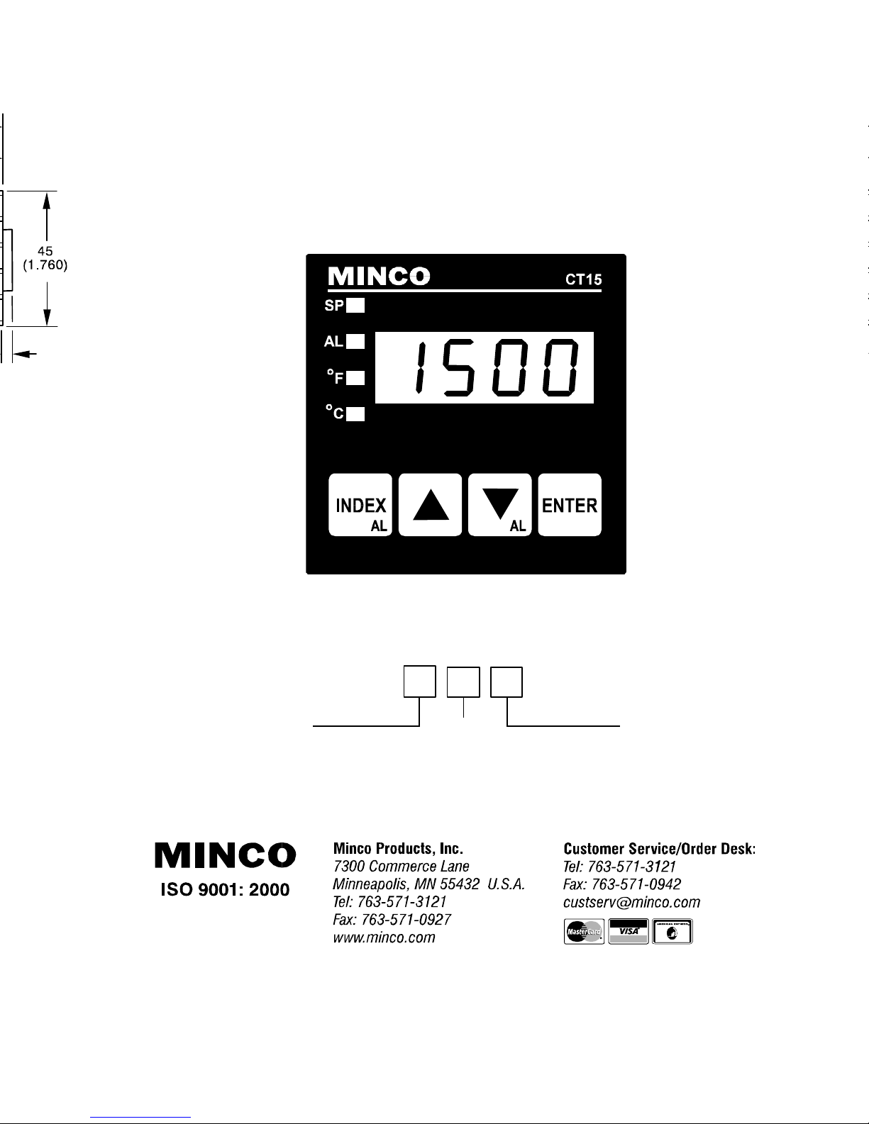
INSTRUCTIONS FOR THE CT15 SERIES
MICROPROCESSOR BASED
TEMPERATURE CONTROLLER
MODEL IDENTIFICATION
Model CT15
Alarm
0 = No
1 = Yes
Input
1 = Thermocouple, J, K, T
Ω Platinum RTD
2 = 100
(DIN), element PD
Output
1 = SSR
2 = 5 VDC
3 = Relay
Page 2

Page 2 of 12
TABLE OF CONTENTS
INPUT WIRING .......................................................................................................................3
INSTALLATION.......................................................................................................................3
WIRING ...................................................................................................................................4
FRONT PANEL KEY FUNCTIONS..........................................................................................4
SECURITY LEVEL SELECTION .............................................................................................5
MENU SELECTIONS .............................................................................................................6
PRIMARY MENU.....................................................................................................................6
SECONDARY MENU ..............................................................................................................6
SECURE MENU ......................................................................................................................7
ALARM TYPE AND ACTION...................................................................................................8
DIAGNOSTIC ERROR MESSAGES .....................................................................................10
SPECIFICATIONS.................................................................................................................11
DIMENSIONS........................................................................................................................12
GETTING STARTED
1. Install the control as described on page 3.
2. Wire your control following the instructions on page 3 and drawing on page 4.
3. Most controls do not need many (if any) program changes to work on your process. For best
results if programming changes are necessary, make all the necessary changes in the
SECURE MENU (page 7) before making changes to the SECONDARY MENU (page 6). If
error messages occur, check the Diagnostic Error Messages on page 10 for help.
Take the example of a Model CT15011 that comes from the factory programmed for type J
thermocouples. Suppose for this example you wish to change the input to type K and limit the
set point range between 0° and 1000° C.
First, enter the SECURE MENU as instructed on page 7. Press the INDEX key until the display
shows
Inp
and press the DOWN ARROW until the display shows CA. Don't forget to press the
ENTER key to retain your setting.
Next, press the INDEX key to display
F-C
. Press the DOWN ARROW until the display shows C.
Press ENTER.
Next, press the INDEX key until
UP ARROW until the display shows
Finally, press INDEX key to display
1000
. Press ENTER.
SPL
is displayed (pass the
0
. Press ENTER.
SPH
. Press the DOWN ARROW until the display shows
dPt
and
InPt
selections). Press the
The necessary program changes are now complete. After 30 seconds the display will switch
back to the temperature reading. If you want to return faster, press the UP ARROW and ENTER
keys (at the same time) and then press the DOWN ARROW and INDEX keys ( again at the same
time). This will 'back out' of the menu and immediately display the temperature reading.
Page 3
Page 3 of 12
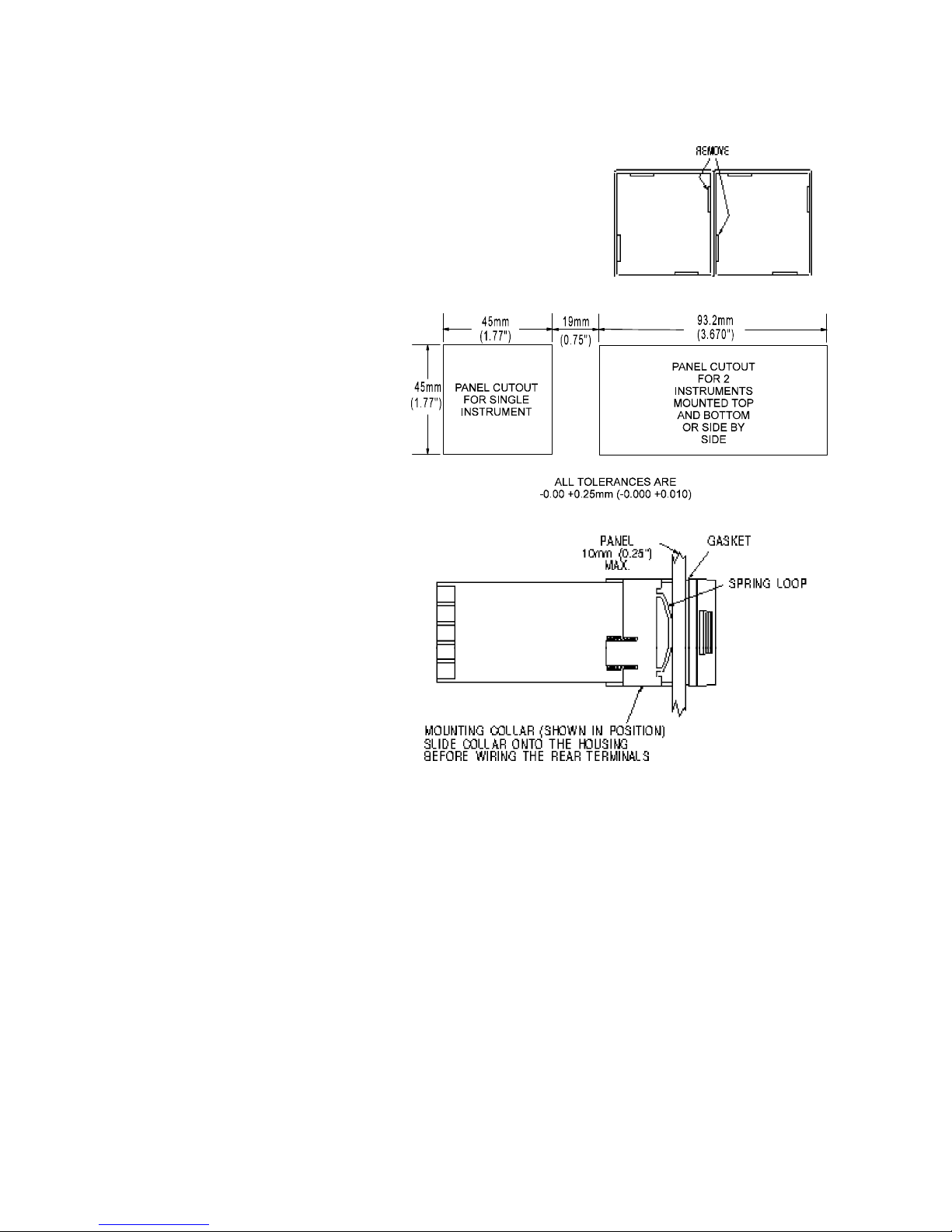
INSTALLATION
Mount the instrument in a location that will not be subject to excessive temperature, shock,
or vibration. All models are designed for mounting in an
enclosed panel.
Select the position desired for the instrument on the panel.
If more than one instrument is required, only two units can
be mounted closely together, either one above the other or
side by side. When mounted together, the mounting collar
will require modification by removing the inside tab from
each collar.
Prepare the panel by cutting
and deburring the required
opening.
From the front of the panel,
slide the housing through the
cut out. The housing gasket
should be against the housing
flange before installing.
From the rear of the panel slide
the mounting collar over the housing. Hold the housing with one
hand and using the other hand,
push the collar evenly against the
panel until the spring loops are
slightly compressed. The ratchets will hold the mounting collar
and housing in place.
INPUT WIRING
Do not run thermocouple or other input wiring in the same conduit as power leads. Use only the type
of thermocouple or RTD probe for which the control has been programmed. See the "
MENU
" to change between RTD and thermocouple input types.
For thermocouple input always use extension leads of the same type designated for your thermocouple.
SECURE
Page 4
Page 4 of 12
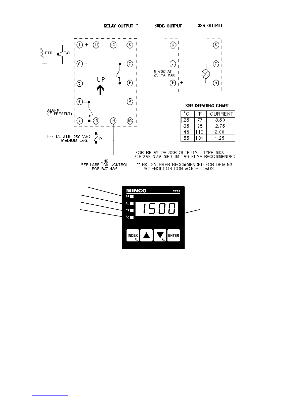
WIRING
FRONT PANEL KEY FUNCTIONS
Set Point Lamp
Alarm Lamp
°F Indicator*
°C Indicator* Decimal point
flashes while
*Lamp flashes during ramping function
Self-Tune operation. is active.
The 1500 Series controls have one display. The display must occasionally switch to show
a complete message or menu item and its value. The normal display shows just the
temperature and does not switch. While showing a menu item, the display will alternate
between the menu item and the item value. If the UP arrow, DOWN arrow, or ENTER keys
are pressed, the display immediately switches to display the item value.
Key functions are as follows:
1. INDEX: Pressing the INDEX key advances the display to the next menu item. May
also be used in conjunction with other keys as noted below.
2 UP ARROW: Increments a value, changes a menu item, or selects the item to ON.
The maximum value obtainable is 9999 or 999.9.
3. DOWN ARROW: Decrements a value, changes a menu item, or selects the item to
OFF. The minimum value obtainable is -1999 or -199.9.
4. ENTER: Pressing ENTER stores the value or the item changed. If not pressed, the
previously stored value or item will be retained. The display will flash once when
ENTER is pressed.
5. UP ARROW & ENTER: Pressing these keys simultaneously brings up the
SECONDARY MENU starting at the alarm, tune, or cycle item (depending on
programming). Pressing these keys for 5 seconds will bring up the SECURE MENU.
Page 5

Page 5 of 12
6. INDEX & DOWN ARROW: Pressing these keys simultaneously will allow backing up
one menu item, or if at the first menu item they will cause the display to return to the
PRIMARY MENU. If an alarm condition has occurred, these keys may be used to reset
the alarm.
7. INDEX & ENTER: Pressing these keys simultaneously and holding them for 5
seconds allows recovery from the various error messages. The following menu items
will be reset:
ALiH: Alarm inhibit OPEn InP: Thermocouple error message
bAd InP: RTD error message CHEC CAL: Check calibration error message
Correct the problems associated with the above conditions first before using these reset
keys. More than one error could be present. Caution is advised since several items are
reset at one time.
While in the PRIMARY or SECONDARY MENU, if no key is pressed for a period of 30
seconds, the display will return to the HOME position displaying the temperature value. The
time is increased to 1 minute when in the SECURE MENU.
NOTE: To move to the PRIMARY MENU quickly from any other menu, press the UP
ARROW & ENTER keys followed by pressing the INDEX & DOWN ARROW keys.
SECURITY LEVEL SELECTION
NOTE: Lock menus to prevent unauthorized changes to controller settings.
Four levels of security are provided. The security level can be changed under SECr in the
SECURE MENU. The display shows the current security level. Refer to the password table
below for the correct value to enter for the security level desired. To change security levels,
set the password value using the UP & DOWN ARROW keys and press the ENTER key.
The SECr menu item's security level may be viewed or changed at any time regardless of
the present security level. The password values shown in the table cannot be altered, so
retain a copy of this page for future reference. This will be the only reference made to
password values in this instruction book.
SECURITY LEVEL
MENU SECURITY
Primary Locked
Secondary Locked
Secure Locked
Primary Unlocked
Secondary Locked
Secure Locked
Primary Unlocked
Secondary Unlocked
Secure Locked
Primary Unlocked
Secondary Unlocked
Secure Unlocked
PASSWORD TABLE
DISPLAYED VALUE
WHEN VIEWED
1
2
3
4
PASSWORD
VALUE TO ENTER
1110
1101
1011
111
Page 6

Page 6 of 12
MENU SELECTIONS
PRIMARY MENU
Press INDEX to advance to the next menu item. Press UP ARROW or DOWN ARROW
to change the value in the display. Press ENTER to retain the value.
SP Set Point Adjust, Control Point.
SECONDARY MENU
Press UP ARROW & ENTER simultaneously. Press INDEX to advance to the next menu
item. Press UP ARROW or DOWN ARROW to change the value in the display. Press
ENTER to retain the value.
ALLo Alarm Low: The Low Alarm point is usually set below the Set Point.
ALHi Alarm High: The High Alarm Point is usually set above the Set Point.
CY Cycle Rate and output selection: Select OnOF, 1, 2 to 80 seconds total cycle time.
ONOF A setting of ONOF allows the control to operate as a simple on/off mode.
This setting forces the control to turn off at set point, and on at the set point
plus the differential (SP_d). When selected, the tunE, Pb, rES, OFS, rtE,
and ArUP selections in the Secondary menu and the SPOL and SPOH
selections in the Secure menu are suppressed.
1 A setting of 1 is recommended for solid state outputs (SSR or 5VDC).
2 to 80Time Proportioning Control is adjustable in 1 sec. steps. Recommended for
mechanical outputs (relays, solenoids, etc.). For best contact life, a time
should be selected that is as long as possible without causing the process
to wander.
SP_d Set Point On-Off Differential. (Only appears if CY is set to ONOF.) Select 1 to 999°F.
This value will be negative for reverse acting set points, and positive for direct acting
outputs. Set the value for the amount of temperature difference between the turn
off point (set point) and the turn on point.
tunE Tuning Choice: Select SELF or Pid.
SELF The Controller will evaluate the Process and select the PID values to
maintain good control. The ramp function (rt) cannot be selected while
SELF tunE is active. The temperature descriptor will flash while SELF tunE
is active. The control will switch to Pid tunE when the tuning function is
complete.
Pid Manually adjust the PID values. PID control consists of three basic
parameters, Proportional Band (Gain), Reset Time (Integral), and Rate
Time (Derivative).
Pb Proportional Band (Bandwidth): Select 5 to 5000 °F (3 to 2778 °C).
rES Automatic Reset Time: Select OFF, 0.1 to 99.9 minutes. Select OFF
to switch to OFS.
OFS Manual Offset Correction: Select OFF, 0.1 to 99.9%. Select OFF to
switch to rES.
rtE Rate Time. Select OFF, 0.01 to 99.99 minutes (Derivative).
Page 7

Page 7 of 12
ArUP Anti- Reset Wind-up Feature: Select On or OFF.
On If ArUP is On the accumulated Reset Offset value will be cleared to 0%
when the process input is not within the Proportional Band.
OFF If ArUP is OFF, the accumulated Reset Offset Value is retained in memory
when the process input is not within the Proportional Band.
rt Ramp Time: Select OFF, 00.01 to 99.59 (HH.MM). When value is entered, control
calculates a ramp slope from the current temperature to SP over the time entered.
Changing rt or SP (or pressing ENTER at either menu item) restarts the ramp
function, and re-calculates the slope. The right hand decimal point of the display
will flash while the ramp function is active. Self tunE cannot be selected while the
ramp function is active. Selecting OFF will stop a current ramp and drive the output
as necessary to reach set point
InPC Input Correction: Select ±500 °F (±278 °C). This feature allows the input value to
be changed to agree with an external reference or to compensate for sensor error.
Note: InPC is reset to zero when the input type is changed, or when decimal
position is changed.
FiLt Digital Filter: Select OFF, 1 to 99. In some cases the time constant of the sensor,
or noise could cause the display to jump enough to be unreadable. A setting of 2
is usually sufficient to provide enough filtering for most cases, (2 represents
approximately a 1 second time constant). When the 0.1 degree resolution is
selected this should be increased to 4. If this value is set too high, controllability
will suffer.
SECURE MENU
Hold UP ARROW & ENTER for 5 Seconds. Press INDEX to advance to the next menu item.
Press UP ARROW or DOWN ARROW to change the value in the display. Press ENTER
to retain the value.
SECr Security Code: See the Security Level Selection and the Password Table in this
manual in order to enter the correct password.
InP Input Type: Select one of the following. The selections are limited to the input type
you ordered. If you ordered a thermocouple input control, make your selection from
the thermocouple list. If you ordered an RTD input, select from the RTD list.
Thermocouple selections:
J-IC Type “J” Thermocouple, Iron/Constantan (NIST)
CA Type “K” Thermocouple Chromel/Alumel
t- Type “T” Thermocouple Copper/Constantan
RTD selection:
P385 100 ohm Platinum (DIN 0.00385
Ω/Ω/°C), element code PD.
F-C Select temperature descriptor for Fahrenheit or Celsius.
F °F descriptor is On and temperature inputs will be displayed in actual
degrees Fahrenheit.
C °C descriptor is On and temperature inputs will be displayed in actual
degrees Celsius.
dPt Decimal Point Positioning: Select 0 or 0.0. This only affects the Process Value, SP,
ALLo, ALHi, and InPC.
0 No decimal Point is selected.
0.0 One decimal place is selected. If the Process Value moves outside of the
decimal point range ends (-199.9 to +999.9), the Process Value display will
autorange to whole degree resolution. When the Process Value returns to
the decimal point range, the display will autorange back to tenth degree
resolution.
Page 8

Page 8 of 12
InPt Input Fault Timer: Select OFF, 0.1 to 540.0 minutes. Whenever an Input is out of
range (UFL or OFL displayed), shorted, or open the timer will start. When the time
has elapsed, the controller will revert to a safe condition (Output Off, Flashing
Display). If OFF is selected, the Input Fault Timer will not be recognized (time =
infinite).
SPL Set Point Low: Select from the lowest input range value to SPH value. This will set
the minimum SP value that can be entered. The value for SP will stop moving when
this value is reached.
SPH Set Point High: Select from the highest input range value to SPL value. This will set
the maximum SP value that can be entered. The value for SP will stop moving when
this value is reached.
SPSt Set Point State: Select dir or rE.
dir Direct Action. As the input increases the output will increase. Most com-
monly used in cooling processes.
rE Reverse Action. As the input increases the output will decrease. Most
commonly used in heating processes.
SPOL Set Point Output Low Limit: Select 0 to 100% but not greater than SPOH. This item
limits the lowest output value. This is useful for adding a bias to the process when
needed.
SPOH Set Point Output High Limit: Select 0 to 100% but not less than SPOL. This item
allows setting the maximum output limit. This is useful with processes that are overpowered.
SPLP Set Point Lamp: Select O on or OoFF.
O on Lamp ON when Output is ON.
OoFF Lamp OFF when Output is ON.
ALARM TYPE AND ACTION (if present)
Caution: In any critical application where failure could cause expensive
product loss or endanger personal safety, a redundant limit controller is
required.
When setting an alarm value for an absolute alarm (ALt = AbS), simply set the value at
which the alarm is to occur.
When setting the alarm value for a deviation alarm (ALt = dE), set the difference in value
from the Set Point (SP) desired. For example, if a low alarm is required to be 5 degrees
below the SP, then set ALLo to -5. If a high alarm is required 20 degrees above the SP, then
set ALHi to +20. If SP is changed, the alarm will continue to hold the same relationship as
originally set.
The diagram at the top of the next page shows the action and reset functions for both
absolute and deviation alarms.
When Alarm Power Interrupt, ALPi, is programmed ON and Alarm Reset, ALrE, is
programmed for Hold, the alarm will automatically reset upon a power failure and
subsequent restoration if no alarm condition is present.
If Alarm Inhibit, ALiH, is selected ON, an alarm condition is suspended upon power up until
the process value passes through the alarm set point once. Alarm inhibit can be restored
as if a power up took place by pressing both the INDEX and ENTER keys for 5 seconds.
Warning: Resetting a high alarm inhibit will not cause an alarm to occur
if the Process Value does not first drop below the high alarm setting. Do
not use the Alarm Inhibit feature if a hazard is created by this action. Be
sure to test all combinations of high and low alarm inhibit actions before
placing control into operation.
Page 9

Page 9 of 12
D = deviation
The following menu items apply only to the alarm.
AL Alarms: Select OFF, Lo, Hi, or HiLo.
OFF Alarms are turned OFF. No Alarm menu items appear in the Secondary and
Secure menus.
Lo Low Alarm Only. ALLo appears in the Secondary Menu.
Hi High Alarm Only. ALHi appears in the Secondary Menu.
HiLo High and Low Alarms. Both share the same Alarm Relay output.
ALt Alarm Type: Select AbS or dE
AbS Absolute Alarm that may be set anywhere within the values of SPL and SPH
and is independent of SP.
dE Deviation Alarm that may be set as an offset from SP. As SP is changed the
Alarm Point will track with SP.
ALrE Alarm Reset: Select OnOF or Hold.
OnOF Automatic Reset.
Hold Manual Reset. Acknowledge (reset) by simultaneously pressing the INDEX
& DOWN ARROW keys for 5 sec.
ALPi Alarm Power Interrupt: Select On or OFF.
On Alarm Power Interrupt is ON.
OFF Alarm Power Interrupt is OFF.
ALiH Alarm Inhibit: Select On or OFF.
On Alarm Inhibit is ON. Alarm action is suspended until the process value first
enters a non-alarm condition.
OFF Alarm Inhibit is OFF.
ALSt Alarm Output State: Select CLOS or OPEn.
CLOS Closes Contacts at Alarm Set Point.
OPEn Opens Contacts at Alarm Set Point.
ALLP Alarm Lamp: Select O on or OoFF.
O on Alarm Lamp is ON when alarm contact is closed.
OoFF Alarm Lamp is OFF when alarm contact is closed.
Page 10

Page 10 of 12
DIAGNOSTIC ERROR MESSAGES
DISPLAY
UFL
or
OFL
bAd
InP
OPEn
InP
CHEC
CAL
MEANING
Underflow or Overflow:
Process value has exceeded input range ends.
UFL
or
OFL
will sequence
to display one of these
messages if the
InPt
is set
for a time value.
For RTD inputs RTD is
open or shorted.
For THERMOCOUPLE inputs thermocouple is open.
Check calibration appears
as an alternating message
if the instrument calibration nears tolerance edges.
Check calibration appears
as a flashing message if
the instrument calibration
exceeds specification.
SP OUTPUTS
Set point output
active
Alarms active
Set point output
inactive
Alarms active
Set point output
active
Alarms active
Set point output
inactive
Alarms active
ACTION REQUIRED
Input signals may normally go above
or below range ends. If not, check
input and correct.
To reset use the
keys. When
INDEX
InPt
(input fault timer)
&
ENTER
has been set for a time, the outputs
will be turned off after the set time.
Setting the time to OFF causes the
outputs to remain active, however
UFL
or
OFL
will still be displayed.
Correct or replace sensor. To reset
use the
INDEX
&
ENTER
keys.
Remove the instrument for service
and / or recalibration. To reset use the
INDEX
&
ENTER
keys.
Remove the instrument for service
and / or recalibration. To reset use the
INDEX
&
ENTER
keys.
No dis-
play
lighted
FAIL
tESt
CHEC SP
CHEC ALLO
CHEC ALHi
CHEC
SPL
or
CHEC
SPH
Display is blank. Instrument may not be getting
power, or the supply voltage is too low.
Fail test appears upon
power up if the internal diagnostics detect a failure.
This message may occur
during operation if a failure
is detected. Displays flash.
This message will appear
upon power up if the set
point is set outside of the
SPL
or
SPH
values.
This message appears at
power up if
SPL
or
SPH
values are programmed
outside the input range
ends.
Set point output
inactive
Alarms inactive
Set point output
inactive
Alarms inactive
Set point output
inactive
Alarms active
Set point output
inactive
Alarms inactive
Check that the power supply is on, or
that the external fuses are good.
The display alternates between
tESt
and one of the following messages:
corrupted. Press the
the
FACt dFLt
: Memory may be
DOWN ARROW
ENTER
key to start the
FAIL
key and
factory default procedure. Re-check
controller programming.
rEt FACt
:
Can not recover from error, return to
factory for service.
Correct the
SPH
values by programming new
SP
or adjust the
SPL
or
values.
Correct the
SPL
or
SPH
values by
programming new values.
Page 11

Page 11 of 12
Input Ranges (as ordered)
Thermocouple Types
Input Type
-
Temperature
Range & Unit
of measure
1°F
1°C
Type J
Iron-
Constantan
-100 to +1600
-73 to +871
Type K
Chromel-
Alumel
-200 to +2500
-129 to +1371
Type T
Copper-
Constantan
-350 to +750
-212 to +398
RTD Type
100 Ohm Platinum
0.00385 DIN Curve
element code PD
-328 to +1607
-200 to +875
SPECIFICATIONS
Selectable Inputs: Thermocouple or RTD as ordered.
Input Impedance:
Thermocouple = 3 megohms minimum. RTD current = 200 uA.
Sensor Break Protection: De-energizes control output to protect system.
Set Point Range: Selectable (See range chart above).
Display: One; 4 digit, 7 segment, 0.3" high LEDs.
Control Action: Selectable for Reverse (usually heating) or Direct (usually cooling).
Ramp: One ramp time adjustable from 0 to 100 hours.
Proportional Band: 5 to 5000 °F or equivalent °C.
Reset Time (Integral): Off or 0.1 to 99.9 minutes.
Rate Time (Derivative): Off or 0.01 to 99.99 minutes.
Cycle Rate: 1 to 80 seconds, and on-off.
On - Off Differential: Adjustable 1° F to 999°F in 1° steps (equivalent °C).
Alarm On - Off Differential: 2° F or equivalent in °C.
Accuracy: ±0.25% of span, ±1 degree.
Resolution: 1 degree or 0.1 degree, selectable.
Line Voltage Stability: ±0.05% over the supply voltage range.
Temperature Stability: 4µV/°C (2.3 µV/°F) typical, 8 µV/°C (4.5 µV°F) maximum.
Common Mode Rejection: 140 db minimum at 60 Hz.
Normal Mode Rejection: 65 db typical, 60 db at 60 Hz.
Isolation: Relay and SSR outputs are isolated. 5VDC output must not share a common
ground with the input.
Supply Voltage: 100 to 240 VAC, nom., +10 -15%, 50 to 400 Hz. single phase; 132 to 240
VDC, nom., +10 -20%.
Power Consumption: 5VA maximum.
Operating Temperature Range: -10 to +55 °C (+14 to 131 °F).
Storage Temperature Range: -40 to +80 °C (-40 to 176 °F).
Operating Humidity Range: 0 to 90% up to 40 °C non-condensing. 10 to 50% at 55 °C
non-condensing.
Memory Backup: Non-volatile memory. No batteries required.
Control Output Ratings:
1. SSR, 3.5 A @ 250 VAC at 25 °C. Derates to 1.25 A @ 55 °C. Minimum 48 VAC and
100 mA required.
2. Switched voltage (non-isolated): 5 VDC @ 25 mA.
3. Relay, Form A contact (SPST), 3 A @ 250 VAC resistive; 1.5 A @ 250 VAC inductive;
Pilot Duty Rating: 250 VA, 2 A @ 125 VAC or 1 A @ 250 VAC.
Alarm Relay Rating: Same as Control Output Relay.
Weight: 227 g (8 oz).
Agency Approvals: UL E83725, and CSA LR40125.
Front Panel Rating (non-hazardous locations): Designed to meet UL 4X for non-
hazardous locations (equal to NEMA rating).
Page 12

Page 12 of 12
DIMENSIONS
(All dimensions in mm with inches in parentheses.)
Panel cutout for all models 45 mm X 45 mm (1.775" X 1.775"). Allow for
13 mm (0.5") clearance at the rear of instrument.
*Present for SSR and 5 VDC output.
LIMITED WARRANTY
Minco Products, Inc. warrants to the Buyer that any equipment sold will be free from
defects in material or workmanship. If, at any time within thirtysix (36) months after
shipment of CT15 Series Controls or within three (3) months after shipment of other
assemblies or parts, the Seller is notified of such defect and the defective item is returned
to Seller by Buyer, transportation prepaid, for examination, the Seller will, at his option,
either repair or replace the defective items.
This warranty shall be effective only if installation and maintenance is in accordance with
Seller's instructions and the defect is not caused by shipping damage, misuse or abuse
by the Buyer. There are no other warranties, written, oral, or implied. The liability of the
Seller is limited to the repair or replacement of the defective item as set forth above.
Items which wear or are perishable by misuse are not warranted. These include, but are
not limited to, relays, contact points, lamps, LEDs, load SCRs, SSRs, and triacs.
© 1994, MINCO PRODUCTS, INC. ALL RIGHTS RESERVED. NO PORTION MAY BE COPIED WITHOUT THE
EXPRESS WRITTEN CONSENT OF MINCO PRODUCTS, INC.
G:\MOD\CT15\LIT\759MN.PM5
7/03
360-00066
 Loading...