

Page 1
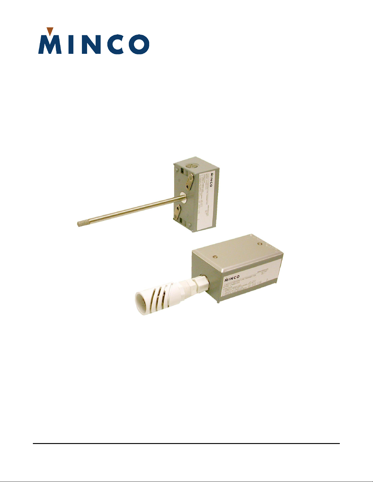
AH440 Humidity and Temperature Transmitter
Installation and Operating Instructions
Tel: 763. 571.3121 • Fax: 763. 571.0927 • www.minco.com
Page 2

Description
Model AH440 is humidity / temperature assembly consisting of separate 2-wire temperature compensated
humidity and temperature transmitters, as well as a rugged sensing probe. The assembly utilizes a Honeywell
HIH series monolithic IC humidity sensor, which provides excellent stability and chemical resistivity. The
humidity transmitter converts the humidity sensor’s signal into a 4 to 20 mA DC current, which changes
proportionally from 4 mA at 0% RH to 20 mA at 100% RH. The leads that supply power also carry the current
signal. The additional temperature transmitter provides a second 4 to 20 mA DC output where the current
changes from 4 mA at the lowest temperature of the range, to 20 mA at the top of the temperature range.
The range of the temperature transmitter can be re-scaled via dip-switches. These transmitters have noninteracting, field adjustable zero and span pots and are available in duct mount, wall mount, outside air (OSA),
and space mount configurations.
Specifications
Output(s):
Sensing Element:
Ambient Temperature:
Operating:
Storage:
Supply voltage:
Voltage effect:
Loop resistance:
Accuracy:
Humidity:
Temperature:
Adjustments:
Time Constant:
Connections:
Weight:
Minimum output current:
Maximum output current:
Humidity: 4 to 20 mA DC = 0% to 100% RH.
Temperature: 4 to 20 mA DC over specified range.
Humidity: Capacitive monolithic IC.
Temperature: 1000 ohm platinum; 2 lead RTD.
Room: -10 to 150°F (-23 to 65°C), non-condensing.
Duct/Wall/OSA: -10 to 185°F (-23 to 85°C), non-condensing.
Room: -58 to 150°F (-50 to 65°C), non-condensing.
Duct/Wall/OSA: -58 to 185°F (-50 to 85°C), non-condensing.
9.5 to 35 VDC, non-polarized.
.001% of span/volt from 9.5 to 35 VDC.
The maximum allowable resistance of the signal-carrying loop, including
extension wires and load resistors, is given by this formula: R
9.5)/0.02 AMPS. For example, if supply voltage is
24 VDC, the loop resistance must be less than 725Ω.
Includes temperature, linearity, hysteresis, repeatability, and voltage effects.
±1% from 10% to 80% RH @ 25 to 35°C or ±2% from 0% to 90% RH @ 25°C.
(±3% from 0% to 90% RH @ 15 to 50°C).
(±5% from 0% to 90% RH @ 0 to 82°C).
± 0.75% of span for 32 to 122°F ambient
± 1.5% of span for -13 to 185°F ambient
Zero and Span field adjustments, non-interacting.
50 seconds in slow moving air.
Screw terminals (22-14 AWG wire).
1.77 lb (0.81 kg).
3.5 mA.
23 mA.
loopmax
= (V
supply
-
Minco Tel: 763. 571.3121 • Fax: 763. 571.0927 • www.minco.com 2
Page 3

Installation Do’s and Don’ts
Do:
• Check the label and verify the model number of the unit.
• Confirm the required power and signal wires are available at installation site.
• Avoid electrical interference with other signals by using twisted pair wiring. Do not run signal leads
near or parallel to line voltage or other power leads.
• Mount the unit on an interior wall located away from air drafts coming from forced air heating/cooling
vents, within the wall and/or the wiring conduit.
Don’t:
• Do not touch or manipulate the sensors.
• Do not expose the sensor to direct light during installation. This causes a false reading. Should this
occur, shade the sensor. It will self-adjust and yield an accurate reading in less than two minutes.
• Do not expose the sensor or transmitter to static electricity. This device incorporates CMOS
components which are vulnerable to damage via static charges.
Mounting
Installation of the AH440 consists of mounting the transmitter and connecting it to power.
Duct/Wall/OSA Mounting: Models AH440D… AH440O… AH440W
1. For the duct mount model AH440D only, drill ½” hole into sheet metal of duct. (Probe is 3/8” in
diameter.)
2. Remove the rubber cap from the end of the probe.
3. Using the fold-out tabs on bottom of housing, mount housing to sheet metal.
4. Remove transmitter cover and connect power wires to the transmitter by 2 screw terminals located
near the edge of the circuit board (Figure 2). Power supply must not exceed 35 VDC.
5. Re-install cover.
Minco Tel: 763. 571.3121 • Fax: 763. 571.0927 • www.minco.com 3
Page 4

Humidity Transmitter Wiring Diagram
Figure 1
Temperature Transmitter Wiring Diagram
Figure 2
Minco Tel: 763. 571.3121 • Fax: 763. 571.0927 • www.minco.com 4
Page 5

Power Supply
DC power supply requirements are determined by the humidity and temperature transmitter’s minimum
voltage requirement and voltage drop across the load resistor and installation lead wires.
Example: The transmitter requires 9.5 Volts minimum. A typical 250 ohm load resistor drops 5.0 Volts @ 20 mA.
Allowing a margin of 0.5 Volts for the supply permits 25 ohms of lead wire resistance for remote installation.
Totaling these, we get a minimum power supply requirement of 15.0 VDC.
Using a 24 VDC power supply will take care of nearly all installations, but the AH440 will operate at voltages up
to 35 VDC.
Humidity Transmitter Calibration
Calibration of the humidity transmitter can be done in a number of ways; comparison to another calibrated RH
instrument, using saturated salts, or in a controlled environment using a humidity chamber. The humidity and
temperature transmitters have non-interacting zero and span pots for field calibration.
Comparison method
To compare the calibration of the AH440 to another calibrated RH instrument, both sensors should be within
2” to 3” of each other with a fan blowing on both sensors for at least 10 minutes. This will equalize the
temperature of both sensors and emulsify the moisture content of the air. If adjustment is needed, adjust the
humidity zero (HZ) pot only. Refer to wiring diagrams 1-4 for location of the adjustment pots. Do not adjust
the span control.
Saturated Salts
Calibration is accomplished using saturated salt calibration cells as humidity standards. The cells are designed
for field use in constant temperature conditions. Various types of cells and their respective relative humidity
values are available. The cells must accept a 3/8” diameter probe. If adjustment is needed, and you’re
performing a single point calibration, adjust the humidity zero (HZ) pot only. For 2 point calibrations, use the
humidity zero (HZ) pot to adjust the low humidity calibration point and the humidity span (HS) pot to adjust
the high humidity calibration point.
Humidity Chamber
Follow the instructions of the humidity chamber for simulating humidity and temperature under controlled
conditions. If adjustment is needed, and you’re performing a single point calibration, adjust the humidity zero
(HZ) pot only. For 2 point calibrations, use the humidity zero (HZ) pot to adjust the low humidity calibration
point and the humidity span (HS) pot to adjust the high humidity calibration point. If the humidity span (HS)
pot is adjusted, go back and verify that unit is still within calibration at the low humidity calibration point.
Temperature Transmitter Calibration
Temperature Chamber/bath
Follow the instructions of the temperature chamber or bath simulating temperature under controlled
conditions. If adjustment is needed, and you’re performing a single point calibration, adjust the temperature
zero (TZ) pot only. For 2 point calibrations, use the temperature zero (TZ) pot to adjust the low temperature
calibration point and the temperature span (TS) pot to adjust the high Temperature calibration point. If the
temperature span (TS) pot is adjusted, go back and verify that unit is still within calibration at the low
temperature calibration point.
Minco Tel: 763. 571.3121 • Fax: 763. 571.0927 • www.minco.com 5
Page 6

Warranty
Items returned within one year from the date of sale, transportation prepaid, which Minco Products, Inc. (the
“seller”) reasonably determines to be faulty by reason of defective materials or faulty workmanship will be
replaced or repaired at the seller’s discretion, free of charge.
This remedy is to be the sole and exclusive remedy available to the buyer in the event of a breach by the seller.
Items that show evidence of mishandling or misapplication may be returned by the seller at the customer’s
expense.
Furthermore, the seller is not to be held responsible for consequential damages caused by this product except
as required under Minnesota Statutes, Section 336.1-719 (3).
This warranty is in lieu of any other expressed warranty or implied warranty of merchantability or fitness for a
particular purpose, and of any other obligations or liability of the seller or its employees or agent.
How to Order AH440
AH440
N10 Calibration Accuracy: (Humidity Transmitter)
AH440D1N10ST1 ← Sample part number
Model Number:
AH440 – Dual Board Humidity / Temperature Transmitter
D Enclosure:
D = Duct mount, 8” probe length
O = Outside Air/Wall mount, 4” probe length with shield,
weather resistant enclosure
W = Wall mount, 4” probe length, weather resistant enclosure
1 Output: 4 to 20 mA DC
N10 = ±1% from 10% to 80% (25 to 35°C) with NIST certificate
N20 = ±2% from 0% to 90% (25°C) with NIST certificate
S20 = ±2% from 0% to 90% (25°C)
S Temperature Transmitter range:
EN = -20°F to 140°F
S =
0°F to 100°F
A = 20°F to 120°F
BI = 30°F to 130°F
KK = 30°F to 180°F
N = 32°F to 122°F
H = 40°F to 90°F
Consult factory for other possible ranges.
T1 Sensing Element Cover (omitted on “S” space mount models)
T0 = Sintered stainless steel; pressed on cover
T1 = Sintered stainless steel; screw on cover
T2 = Slotted stainless steel; screw on cover (not available on “O” outside air models)
Minco Tel: 763. 571.3121 • Fax: 763. 571.0927 • www.minco.com 6
Page 7

Dimensions
Duct
OSA
Wall
WEATHERPROOF
CONNECTION BOX
MODEL CH317
4.5 REF
2.3
REF
2.3
REF
2.175 REF
8 ±.125
GASKET
SENSING
Ø0.375
LINE
POWER
4.5 REF 4 ±.12
4.5 REF
1.0 REF
AREA
GASKET
7/8 HEX
GASKET
CRIMP FITTING
4 ±.12
2.75 REF
Ø1.250
Ø0.375
Minco Tel: 763. 571.3121 • Fax: 763. 571.0927 • www.minco.com 7
Page 8

Worldwide Headquarters
7300 Commerce Lane
Minneapolis, MN 55432 USA
Tel: 1.763.571.3121
Fax: 1.763.571.0927
sales@minco.com
www.minco.com
European Headquarters
Usine et Service
Commercial, Z.I.
09310 Aston, France
Tel: (33) 5 61 03 24 01
Fax: (33) 5 61 03 24 09
Asia Pacific Headquarters
20 Science Park Road
#02-31 Teletech Park
Singapore Science Park II
Singapore 117674
Tel: (65) 6511 3388
Fax: (65) 6511 3399
ISO 9001:2000 / AS9100B
© Minco 2009
F:\MOD\HT429\LIT\
1089MN.DOC
Stock # 360-00114(B)
082409
Flex Circuits
Thermofoil™ Heaters
Sensors
Instruments
 Loading...