

Page 1

MINCO 820B
Genset Controller Manual
GuiLin Minco Electronic Co., LTD. CHINA
GuiLin Glminco Intelligent Control S&T Co., Ltd.
ADD: Building B-216, Venture park of returned Scholars, Guilin high-tech zone,
GuangXi, CHINA
Tel: +86-773-5812281 5828281
Fax: +86-773-5828281
E-mail: sales@glminco.com xamxiao@hotmail.com
Http: //www.glminco.com
Page 2

- 0 -
Contents
1. Summarize..................................................................................................................................................1
2. Characteristic..............................................................................................................................................1
3. Fixup dimension drawing...........................................................................................................................1
4. Function define and operate instruction .....................................................................................................1
4.1.Operate panel function instruction..................................................................................................1
(1). System menu operate press keys................................................................................................2
(2). LCD display (Genset runs in normal,not setting state or not fault state) ..........................2
(3). Operation keys ...........................................................................................................................2
(4). State indicator light....................................................................................................................3
4.2.Connection port definition................................................................................................................3
5. Parameter setting ........................................................................................................................................4
5.1.Parameter setting instruction ..........................................................................................................4
5.2.System parameter setting................................................................................................................6
5.3.Delay time instruction.....................................................................................................................7
6. Normal failure and handling method..........................................................................................................8
7. Outside wire connection drawing.............................................................................................................10
8. Front and back panel contrast diagram.....................................................................................................12
Page 3
- 1 -
1. Summarize
Minco 820B genset controller adopts high performance microprocessor and industry components. It
has measuring, controlling, protection, four remote control, flexible software setting functions and high
anti-jamming ability. Can display all the measuring parameters, control parameters and genset running
state. Actually meets different types of generator auto control requirements . When the mains supply is
failure, the control system will automaticly give a start signal to start the genset and resume the power
supply in short time; After the mains supply is normal, the control system will unload and shut down
automaticly. Adding the monitoring function of mains supply electric quantity, applies to mains supply
and genset supply automatic transfer power supply system.
2. Characteristic
1. Double processing chip, real virtual value measuring, action smartly;
2. Mains and genset double power manager, Automatic Transfer Switch system;
3. Wide-screen LCD display with back-light;
4. Chinese and English double language menu, mutual operation, can be set and operated individually;
5. Auto start, Auto protection, ATS control;
6. Perfect auto protection, warning details and working statement character display directly, fault record
more than 50 items;
7. Double coolant temp., double oil pressure, fuel level and oil temp. etc connected parameters and so
on;
8. All relay contact capability is above 10A/250VAC/30VDC;
9. Electronic speed adjustment and mechanical speed adjustment control compatible, timing start or
stop and etc. custom setting; -
10. RS232 communication, attached “four remote control” monitor software;
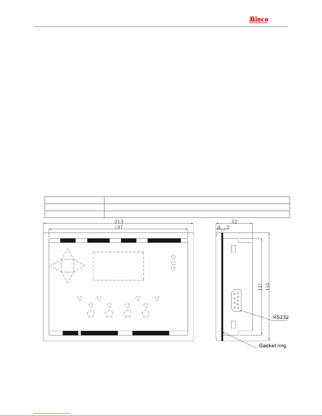
3. Fixup dimension drawing
4. Function define and operate instruction
4.1.Operate panel function instruction
Operate panel is composed of 128X64 LCD display ,operation keys and state indicator light and
system menu operate press keys.
Operate panel W 213 X H 153mm
Install hole W 199 X H 139mm
Deepth D 52mm
Page 4
- 2 -
(1). System menu operate press keys
Content Function
ENT
Parameter setting /enter to next menu / confirm to revise
Exit
Exit / back to the superior menu
+
Switch the screen display content, view all the measuring parameters of the genset and
the current state; Page up the menu / add value
-
Switch the display content; examine all the genset parameters and the current state.
menu page down/degree value
(2). LCD display (Genset runs in normal,not setting state or not fault state)
Operation Description
Main screen 1
Press + or - can switch
the display interface
Normal P 00.0 HZ
A :000 V
B :000 V
C :000 V
Main screen 2
Press + or - can switch
the display interface
Generator 00.0 HZ
A :000 V 0000 A
B :000 V 0000 A
C :000 V 0000 A
Main screen 3
Press + or - can switch
the display interface
Rotate speed: 0000 RPM
Power: 0000.0 KW
Power factor: 0.00
Run Time: 00000.0 H
Main screen 4
Press + or - can switch
the display interface
Coolant temp.: 010/010 (0)
Oil pressure: 999/999 KPa (0)
Oil temp.: 010℃ (0)
Battery: 25.0 V
Main screen 5
Press + or - can switch
the display interface
Stop/OFF status
08-06-03/09:12:15
Attention: If “display change mode” set in “auto” switch state, the LCD display screen will switch to
next page after each 10 seconds; if “background light control” set in “auto” state, the LCD screen
background light will be auto turn off after three minutes without any operate. Once the fault appear or
press any key the background light turns on. If “Background light” control setting as “constant light”,
the LCD background light will keep lighting.
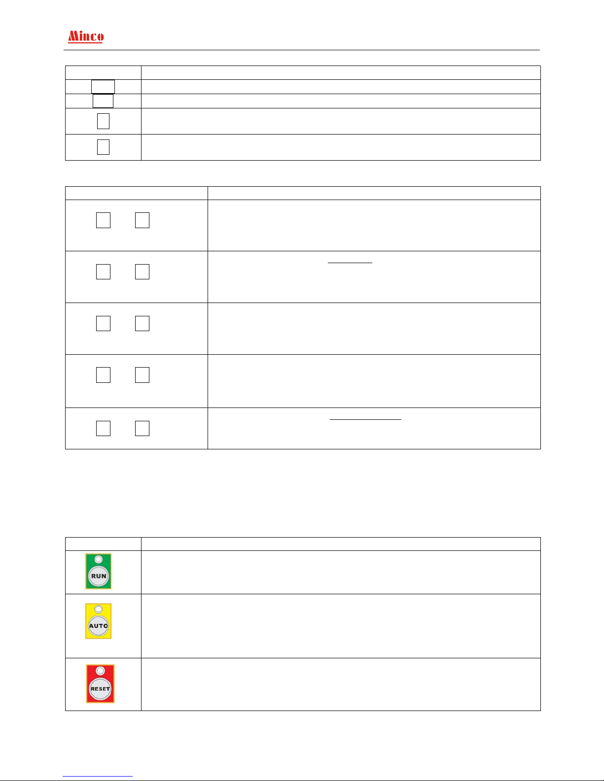
(3). Operation keys
Content Function
Press the key, when the above green LED keep bright, the controller is in “start” state,
start the genset in manual and keep running.
Press the key, when the above yellow LED keep bright, the controller is work in “auto”
state, once the “Remote start” switch input turn off and mains get right, the genset will
be stopped after delay. When “Remote start” switch input turn on the genset delay start
otherwise it’s delay cool down; If the genset reset by “remote reset”, once the “remote
reset” switch input turn off, the controller is in auto state.
Press the key, when the above red LED keep bright, the controller is work in
“stop/reset” state, it will unload, decelerate and idle stop, through idle stop cut off the
fuel. During decelerate and idle the “reset” indicator keep flash, keep light after stop.
Page 5
- 3 -
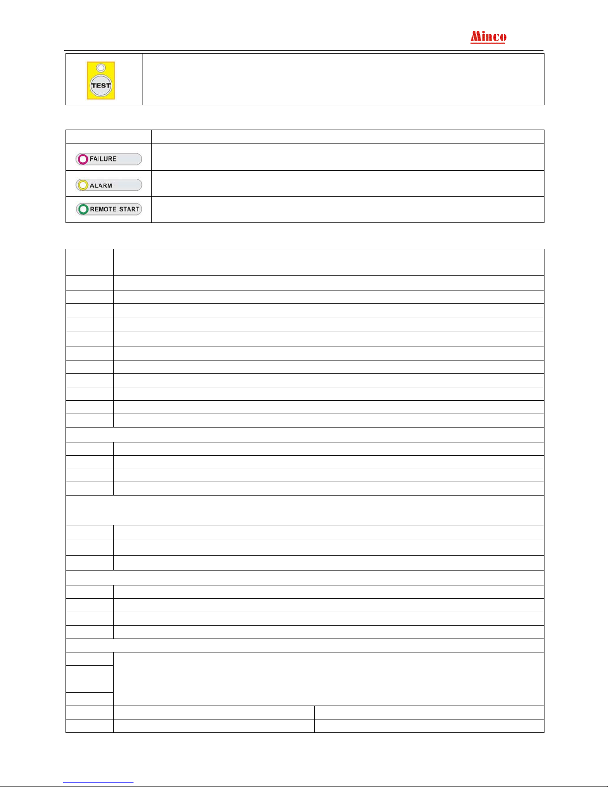
Press the key, when the above red LED keep bright, the controller works in “testing”
state. Start the generator in manual, when the generator runs in normal, whatever the
mains supply is normal or not.The controller will automaticly close, onload and keep
running onloading.
(4). State indicator light
Content Function
Indicate the genset failure, protected stop, fault content display in the LCD sreen.
Indicate the genset warning information, alarm detail see screen.
Indicate “remote start” port state, use in monitor the main state generally.
4.2.Connection port define
Port
No.
Function
Power supply 8~36V DC, normal working current <300 mA
1 battery anode input
2 battery cathode input
Analog input(input voltage range 0~5.0V DC)
3
Analog AGND,inside connect with battery cathode.
4 Oil temp./fuel level input
5 Oil pressure input 1
6 Coolant temp. input 1
7 Oil pressure input 2
8 Coolant temp. input 2
9 User-defined sensor
Main three phase voltage input (0-300VAC,insulation inside)
10 Mains voltage phaseR
11 Mains voltage phase S
12 Mains voltage phaseT
13 Mains zero line N
Three phase load current input(0-5A AC, without inside isolation, must add current
transformer)
14、15
A phase load current
16、17
B phase load current
18、19
C phase load current
Three phase genset voltage input(0-300V AC, voltage transformer with inside isolation)
20 U phase genset voltage
21 V phase genset voltage
22 W phase genset voltage
23 Zero line N
Relay output port(Relay insulated, contact capability 10A/250VAC/30VDC)
24
25
Emergency supply (Genset supply)
26
27
Normal supply (Mains supply)
Electronic governor Mechanical speed control
28 Idle NC (normal closed) Battery negative
Page 6

- 4 -
29 Idle NO (normal open) Battery positive
30 Not connected DC speed adjust motor negative pole
31 Idle common DC speed adjust motor positive pole
32 Pre-fuel
33 Common port 2(Pre-fuel and fault common contact port)
34 Fault
35 Fuel (stop when ETS)
36 Common port 1(Fuel and Crank common contact port)
37 Crank
Switch input port(add photoelectricity insulation,valid when connect to GND)
Electronic governor Mechanical speed control
38 Not connected DECelerate limited
39 Not connected ACCelerate limited
40 High oil temp./low fuel level
41 Low oil pressure
42 High coolant temp.
43 Remote reset
44 Remote start
45 Emergency stop
46
47
Rotate speed signal input
GND, inside connect with battery cathode
5. Parameter setting
All parameters can be read and write through communication port, details see communication
protocol. Except coolant temp., oil press., oil temp./ fuel level sensor option input sensor curve data adjust,
all the parameters can be setting by the controller.
Press ENT
Enter to parameter setting interface
Switch Inputs status Alarm limit set
Relay Outputs status Measure regulate
Shutdown Record Delay time set
Date and time set System set
Press+or-
Select the examine /setting parameter content (reversed display when selected)
Press ENT
Enter to the selected menu
Press Exit
Exit the parameter setting state
Attention: If didn’t press any keys over three minutes it will auto exit the parameter setting state, to avoid
illegimate operation the controller.
5.1.Parameter setting instruction
Switch Inputs
status
Real time display controller input port state
Remote run: 0 Emergency stop: 0
Remote off: 0 High coolant temp.: 0
Acceleration limit: 0 Low oil pressure: 0
Deceleration limit: 0 High oil temp/Low fuel level.: 0
Attention: Press any menu key will be exit
Relay Outputs
status
Real time display controller output port state
Crank: 0 Fuel: 0
Shutdown : 0 Pre-fuel: 0
Normal: 1 Genset: 0
Acceleration: 0 Deceleration: 0
Attention: Press any menu key will be exit
Page 7

- 5 -
Shutdown
Record
Shutdown record
01/04 (Fault serial number/ Fault total number)
Emergency Stop (Fault reason)
08-06-03/11:26:38 (Fault time)
Attention: Press+ , -, display up and down fault record; Press ENT or Exit will
be exit.
Date and time
set
Press+、- to change the reverse display data; Press Exit reverse display move to
the left, move to the first position then press Exit then back to the superior menu,
date and time will not changed; Press ENT reverse display move to the right, move to
the last position press ENT then back to the superior menu, date and time have been
changed.
Alarm limit
set
Default setting:
High Voltage: 0250 High oil temp. : 0100 High acceleration: 1550
Low Voltage: 0200 Low battery: 0105 Low deceleration: 0800
High current: 0450 High frequency: 0530
High Coolant temp. : 0096 Low frequency: 0470
Low oil pressure: 0050 High speed: 1650
Press+ , - choose content and the content reversed display; Press Exit back to
superior menu; Press ENT, enter choosing parameter setting state, the selected
parameter is underline, enter the parameter setting state, press+ , - to change the
reversed display data; Press Exit move to the end of left, press Exit and back to the
superior menu, parameter will be not changed; Press ENT reversed display move to
the end of right, press ENT and back to the superior menu, parameter changed and
saved.
Measure
regulate
Password: 8421(default password of the factory)
Current A: 0000 Normal A: 0000
Current B: 0000 Normal B: 0000
Current C: 0000 Normal C: 0000
Generator A: 0000 Coolant temp. : ----Generator B: 0000 Oil pressure: ----Generator C: 0000 Oil temp./Fuel level: -----
Battery voltage:0120
Attention:Coolant temp. ,oil pressure and oil temp./fuel level adjusting value are
relevant to the real measuring error.
Password authentication input method
Press+、- ,Exit when the selected content move to the end press Exit and back
to the superior menu;Press ENT move to the end of right, enter the password press
ENT then get through the next menu.
Users according the error value of the controller measuring data and the real data
to decide whether you need to data adjust. The controller already adjusted before leave
factory, but it may be some warp in the use environment, if the warp is in the error
range, we suggest not adjusting the data, especially the three phases current. If the
error over too much and need to adjust, please read the <MINCO 820B Genset
controller adjustment instruction>.
Press +、- choose content reversed display, press Exit back to superior
menu; Press ENT enter to choose data adjustment state, and the adjusting parameter
underline.
Enter to data adjusting state, press+、- to change the data, press Exit cursor
turn left, when move to the end, press Exit then back to the superior menu, data
adjustment in valid;Press ENT cursor turn right, move to the fourth position press
Page 8

- 6 -
ENT back to the superior menu ,data adjustment achieved, parameter change saved.
For three phase voltage, three phase current and battery voltage adjustment, enter
data adjust state, change the data then press ENT (Current keep two decimal fraction,
battery voltage keep one decimal).Coolant temp.. oil pressure,oil temp.,fuel level
option input are different, MINCO820B controller provide coolant temp.adjust, oil
pressure adjust,oil temp./fuel level adjust to adjust the measuring data. For the possible
error of the coolant temp.,oil pressure, oil temp./fuel level ,MINCO820B provide ±10
% adjusting range。Special explain, for coolant temp. , oil pressure ,oil temp./fuel
level sensors maybe positive modulus (it means the sensor output added along with
input added), it maybe negative modulus (it means the sensor output minish along with
input added), add or minish adjust value lead to adjust effect decide by the real
situation.
Delay time set
Password input: 8421(default)
Cool stop(down): 020 Idle(stop): 015 Transform: 002
Genset start : 005 Acc.time: 020 Over current: 003
Crank INTerval: 015 Low oil pressure: 003 Over voltage: 003
Crank time: 008 High coolant temp.: 005 Over frequency: 003
Bypass time: 025 Over speed: 002 Warm up: 010
ETS fuel: 030 High oil temp./low fuel level : 005 Dec. time: 030
Pre-fuel: 006 Loss speed: 030
Idle (start): 010 Low battery : 020
Press +、- choose content reversed display;Press Exit back to superior menu;
Press ENT , enter to choose parameter setting state, the adjusting parameter is
underline. Enter the setting state, press +、- to change data, press Exit cursor turn
left, move to the end press Exit back to the superior menu, data will not be changed, if
press ENT parameter change saved. Delay time up limit can’t be over 255 seconds, if
setting over 255 seconds system will change to 255 seconds automatically.
System set
Input password: 8421 (default)
Trip speed: 0400 Speed source: 0 Oil/Fuel select: 1
CT ratio: 0500 Load mode: 0 Phase/Line: 0
Passport: 8421 Coolant source:0 Display mode: 0
Address: 120 Oil pressure source: 003 Language C/E: 1
Crank limit:003 Oil temp. source: 0 LCD mode:1
Gear tooth number:135 Oil temp.action: 0
Opt.2 set: 003 Battery action:1
Press +、-choose content, press Exit back to superior menu, press ENT, enter
the setting state, the adjusting parameter is underline. Press +、- change data, press
Exit data will not be saved, press ENT can be saved the data, then back to the superior
menu.
5.2.System parameter setting
Trip speed
When start the genset, if examine the genset rotate speed >trip speed, it considers the
genset start successful and stop the crank output (trip speed generally setting to 1/3 of
genset normal working rotate speed )
CT ratio
CT rate setting correspond ratio is 5, for example the current rate setting in 500, it’s
correspond with 500:5
Passport
Leave factory password 8421,please change the password on your own.
Address Only use for multi equipment network, to differentiate the equipment.
Crank limit
When Genset starts, if the continuum start failure time over the parameter, it will lead
to overcrank fault.
Page 9

- 7 -
Gear tooth
number
Only valid in “rotate speed measuring method” setting in “speed sensor”
Opt.2 set
Setting coolant temp. 2 and oil pressure 2
0: None coolant temp. 2 and oil pressure 2 1:Only have coolant temp. 2
2: Only have oil pressure 2 3: Have coolant temp. 2 and oil pressure 2
Speed source 0 : From Genset power supply frequency 1 : From Speed sensor
Load mode 0 : Keep 1 : Pulse(cut off after closed 2 seconds)
Coolant
source
0: Coolant temp. alarm switch 1 : Coolant temp. sensor
Oil pressure
source
0 : Oil pressure alarm switch 1 : Oil pressure sensor
Oil temp.
source
0 : Oil temp/fuel level alarm switch 1: Oil temp/fuel level input sensor
Oil
temp.action
0 : Alarm and stop 1 : Alarm but not stop
Battery action
0 : Alarm and stop, 1 : Alarm but not stop
Oil/Fuel select
Configure with oil temp./fuel level input
0 : Define fuel level, 1 : Define oil temp.
Phase/Line 0 : Measuring phase voltage 1: Measuring line voltage
Display mode 0 : Switch in manual 1 : Auto switch
Language C/E
0 : Chinese 1: English
Shortcut method:module power off,press+、- at the same time and afresh electrify
till the language changed.
LCD mode 0 : Auto 1 : Constant light
5.3.Delay time instruction
Delay of “cool
stop(down)”
When the controller is in “Auto” state, once the “Remote start” switch input turn off
and mains get right, the genset will be stopped after delay.
Delay of
“genset start”
When the controller is in “Auto” state, once the “Remote start” switch input turn on or
mains failure , the genset will be started after delay.
Delay of
“cranking
time”
When the genset start and begin to delay,if the start succeed condition is
satisfied(genset rotate speed>trip speed) it’s consider to be genset start successful and
stop delay.
Delay of
“Crank
INTerval”
When the cranking time delay ended, if the start succeed condition is not satisfied and
not reach the crank times limit, the delay will be repeated and crank times added 1.
Delay of
“bypass time”
After the gen-set start successfully, that begin to start delay of the bypass. The term
of delay, not monitor "low oil pressure", "high coolant temperature " etc, to avoid
mistake alarm when gen-set in start early.
Delay of
“ETS fuel”
ETS setting in “0”, controller work as Energize to run (ETR),the fuel supply will have
output until stop; “ETS fuel” delay setting in is not in “0”, the controller work as
energize to stop (ETS), the fuel supply act as stop. The fuel supply relay also have
output when the delay start, the fuel supply relay stop output when delay ended and the
oil pressure be lowed.
Delay of
“pre-fuel”
Before the gen-set to start, that begin the delay of pre-fuel. At the same time, the relay
of “pre-fuel” to closed. After the delay be over, the relay of pre-fuel to open, the
gen-set start to crank.
Delay of “idle
(start) ”
After the gen-set start successfully, the delay of idle (start) is begin, in the term of
delay, the relay of “idle ” begin to work.
Delay of “idle
(stop)”
When stopping machine, the delay of idle (stop) is begin. In the term for delay, the
relay of “idle ” begin to work.
Page 10

- 8 -
Delay of
“ACC”
Genset start successful and idle (start) over, it’s beginning ACC delay, ACC relay
closed, if the delay ended but still not get the ACC in the right position signal, it will
be a “ACC failure” alarm.
Delay of “low
oil pressure ”
When genset running, if the pressure of oil is over low, the delay is begin. In the term
of delay, if the oil pressure comeback normal state, the delay will be interrupt. After
the delay is over, if the oil pressure is over low yet, that will appear the alarm of “low
oil pressure”.
Delay of
“high coolant
temp.”
It is similar to the delay of “low oil pressure alarm”.
Delay of
“over speed”
Start when the genset rotate speed is over the upper limited. If the speed of gen-set
comeback in normal state, the delay will be interrupt. If the speed still over limit when
delay ended, It will be a “ over speed” alarm.
Delay of high
oil temp./low
fuel level
Similar to the delay of “ low oil pressure”
Delay of “loss
speed”
If not detect the speed signal in the term of starting or running, the delay of “lose
speed” is begin. If no yet detect the speed signal, when the delay is over, that will
appear the alarm of “lose speed”.
Delay of “low
battery ”
Similar to the delay of “low oil pressure alarm”.
Delay
“transform”
When the normal supply comeback normal state after gen-set onload it’s action. The
normal supply must be stable for period of time, until the delay retransform is over that
switch to normal supply on load.
Delay of
“ over
current”
It is similar to the delay of “low oil pressure alarm”.
Delay of
“over voltage”
Similar to the delay of “low oil pressure alarm”.
Delay of
“over
frequency”
Similar to the delay of “low oil pressure alarm”.
Delay of
“Dec.time”
Delay of Dec start when the genset stop,Deceleration relay closed,if the delay ended
but still not get the Dec in the right position signal, it will be a “Dec failure” alarm.
Delay of
“warm up”
Happenned during the time when the gen-set starting successfully. To extend the time
of power supply swiching to genset on load. Power supply until the gen-set reach to
optimal state if not emergency, and availably reduce the abrasion.
6. Normal failure and handling method
Failure Describtion Solution
Press the ENT key,the
green light isn’t bright on
the aboved and the motor
doesn’t work.
Check whether the greenlight is broken,if the LED light
isn’t broken,please contact with the factory;If the LED
light is broken,please see below solution.
Manual start
failure
Press the ENT key,the
green light is bright on
the aboved and the motor
doesn’t work.
Check the menu of“low oil pressure”in the “input port
state”,if display “0”,please check whether the oil pressure
sensor is ok;if display “1”,the oil pressure sensor is ok,now
please press START,measuring the module port 34 “start”
whether there’s 24V with a multimeter,if the voltage is
24V,check whether the outside middle relay,start moter is
broken,and whether the battery voltage is enough;If port 34
no output,the module might be damaged.
Page 11

- 9 -
Module in Auto
state,inspection “remote
start” have input, the
“remote start” state light
isn’t bright and the motor
doesn’t work.
Check the menu of “remote start” in the“input state”,if
the “remote start” display “0” means that the outside timer
etc module relay is broken cause didn’t receive the input
signal;If display “1”,the module might be broken.
Auto start
failure
Module in Auto
state,inspection “remote
start” have input, the
“remote start” state light
is bright on and the
motor doesn’t work.
Check the oil pressure sensor; Switch to the manual start,
check whether there’re output signal of the port 34“remote start”, the outside components and the battery
voltage.
Wheel tooth is
fighting when
start
Start successful and
motor keep running, the
whell tooth is fighting.
Lower down the trip speed;
Suggest used speed sensor to get the rotate speed.
On load
current
display
incorrect.
Current ratio setting
incorrected.
Reset the current ratio.
Page 12

- 10 -
7. Outside wire connection drawing
Minco820B Outside wire connection drawing(Mechanical speed control)
Page 13

- 11 -
Minco820B Outside wire connection drawing ( Electronic governor )
Page 14

- 12 -
8. Front and back panel contrast diagram
 Loading...