

MINATO 1866 Instruction Manual
INSTRUCTION
MANUAL


WARRANTY
MINATO
ELECTRONICS Programmer
is
guaranteed against defect in
materials and workmanship.
The warranty period
for
the Model 1866
is
one
(1
) year.
The warranty period begins upon receipt
of
the programmer.
During one (1) year period,
if
the Model 1866 requires any repair due
to
defective materials
or
workmanship contact the
sales
representative.
1.
GENERAL·················································
3
2.
SPECIFICATIONS,
..
, . .... ....... ...... . . ........... .... 3
3. CAUTION..
..
.... ....
..
.... ...... ........ ...... ....
..
..... 4
4. EXTERNAL VIEW AND NAMES
OF
PARTS
.... · 4
4-1
External
View·····································
4
4-2 Display···· . ..... ... . ..... ........ .... ...... ........ 5
4-3 Key Switches
................................
···.. 5
4-4
Rear
Panel
........................................
· 6
4-5 Bottom
Switches................................
6
5. OPERATION.............................................. 7
6.0PERATION
MODES
...................................
7
6-1
EDIT
Mode........................................
7
6-1-1
PAE
(Programming
address
entry
mode)....
.... 7
6-1-2 CH(Change mode) .. ·
..................
9
6-1-3 INS(lnsert mode)
....................
· .. 9
6-1-4 DEL(Delete mode)
..................
· .. 9
6-1-5 INIT(INITIALTZE mode)
..............
10
6-1-6
FORMAT
................................
·10
6-1-7 COMP(COMPLEMENT mode) .... ·10
6-1-8 SER(SEARCH mode)
................
·10
6-1-9
DEVICE
..................................
·10
6-2 SERI(SERIAL I/O
mode)"""'"''''''''''''''
12
2
6-
2-1
Enteri
ng
Data
.......................... · 12
6-2-2 Outputting
..............................
'12
6-2-3 Issuing List
..............................
12
6-2-4 Outputting Control Code
............
12
6-2-5 Handshake
..............................
12
6-3
COPY···············································12
6-4
BLANK··············································13
6-5 PROG(PROGRAM) Mode
.....................
13
6-6 VER(VERIFY) Mode
............................
13
6-7 CONT(CONTINUOUS) Mode
................
·13
6-8 REM(REMOTE) Mode
.........................
13
6-9 Address Mode Selection
......................
13
6-10
AUTO/STEP Selection ...... ·
..................
14
6-11
Check
Sum
......................................
·14
6-12
Error Messages
..................................
14
6-12-1
Table of error codes
................
·14
6-13
Block
Operations
in
Copy,
Program,
Verily
and
Cont
mode
..
15
6-14 Setting Serial I/O Mode
......................
·15
6-15
Others
..............................................
15
6-15-1
Key Lock
................................
15
6-15-2 Test .. ··· .. ·· .... ·· .... ···· .... · .. ···
..
·· ..
16
6-15-3 Repeat
.................................. · 16
CONTENTS
6-15-4 Power-on protection
................
·16
6-15-5 Time-out function
................
· ....
16
7.
REMOTE
OPERATION
................................
17
7-1
Terminal equipment Connection
............
17
7-2 Start of Remote Operation
..............
· .... ·
17
7-3 Creating New
Data"""""""''''''''''''''''
17
7-3-1 How to Use Change Instruction ..
17
7-3-2 How to Use Insert Instruction .... ·
18
7-4 Modifying
Data""""""""""""""""'"
18
7-5 Deleting Data
............................ · ........
19
7-6 Inserting Data
....................................
19
7-7 T ransferri
ng
Data·
........................
· ......
20
7-8 Preparing List
....................................
20
7-9 Punching Paper Tape .. ·
................
· ...... 20
7-10
Reading Data from Paper Tape
............
·21
7-11
Initializing Memory Contents
................
·21
7-12
Programmer
COntrol
.... ·
........................
21
7-12-1
Operation
Address
Range
Specification
........
21
7-12-2 Blank Check ........ ·
..................
21
7-12-3 Program .. ·· .... · .... ··
..
·· .... · .... ·· ....
22
7-12-4 Verify
....................................
·22
7-12-5 Copy
......................................
22
7-12-6 Cont
......................................
22
7-12-7 Format Specification
..............
· ..
22
7-12-8 PTR Verify
..............................
22
7-12-9 Buffer's check sum
..................
22
7-12-10
PROM device select
................
22
7-12-11
Address select
........................
22
7-12-12
EEP-ROM's erase
....................
22
7-12-13
EEP-ROM's byte erase
............
·22
8. SERIAL INTERFACE
..................................
'23
8-1
Introduction .... ·
................ · ................
·23
8-1-1 Serial ifF rati ngs
......................
23
8-1-2 Setting the serial flF
.............. · ..
24
8-1-3 Serial ifF selection
..................
· 25
8-2 RS-232C Level Interface
......................
25
8-2-1
Descriptions
of
interface
signals
........
·25
8-2-2 Interface signal output
..............
26
8-2-3
Connection
to
external
equipment
...... · 27
8-2-3-1
Connection
with
data
terminal
equipment
.. ·28
8-2-3-2
Connoction,,~daIa
COIllmlJ1ication~iJlllent·
'31
8-3 Current Loop Interface
......................
· .. 33
8-3-3
Example
of
connection
with
external
equipment
......
35
8-4 Serial flF Cable
........................
· ........ ·35
8-4-1 Serial I/F Connector
..........
· .... ·
..
35
8-4-2
Table
of
serial
ifF
Connector
pins
.... 36
8-4-3
Cable····································
'37
8-5
Control
Method
and
Transmission
Protocol"'38
8-5-1 Control method
........................
38
8-5-2 Transmission protocol
..............
'40
8-5-2-1 Non-control
................
"40
8-5-2-2 X-ON/X-OFF control ......
·4O
8-6 Instructions in Remote Mode
................
44
8-6-1 Remote Instructions
..................
44
8-6-2 Instructions description
............
·44
8-6-2-1
Instructions
for
deta
transfer········44
8-6-2-2
Instructions
for
P·ROM
control·····
·45
8-6-2-3
Buffer
operation
instructions·····
..
'45
8-7 Instructions in Serial Mode
................
· .. 46
8-7-1 Data format reception
..............
·47
8-7-2 Data format output
..................
-47
8-7-3 List output
............................
"47
8-7-4 Control code output
..................
47
8-7-5
Error
......................................
48
8-8 Data
Fomnat
........ · ..............................
49
8-8-1 Output format
........................
"49
8-8-2 Formats description
................
"50
1.
TEKTRONIX
HEX.
(8 bits) ........ ·50
2.
INTEL
HEX
..........................
· ..
51
2-1
INTEL
HEX.
(8/16 bits) ........
51
2-2 INTEL
HEX
.......................
52
3.
MOTOROLA
........................
"'53
3-1
Motorola Exerciser ...... · ...... 53
3-2 Motorola Exermax
(16
bits)"'53
4.
TEXAS SDSMAC
....................
54
5.
MINATO
HEX
......................
"'54
6.
ASCII-HEX .......
··
..
· ....
··
.... ·
.. · ..
"55
6-1 ASCII-HEX
(SPACE),
V1
...... 55
6-2 ASCII-HEX
(SPACE),
V2
...... 55
6-3 ASCII-HEX
(SPACE),
V3
...... 55
6-4 ASCII-HEX
(SPACE),
V4
...... 55
7.
BINARy
..............................
"'55
8.
HP-64000 ABSOLUTE
............
·'56.
8-3-1 Current Loop Interface
..............
·33 9. Displays and
PROMs
to
be
Programmed
........
..
8-3-2
Current
Loop
interface
signal
output·····34 Contained
in
the pocket at back
of
the rear cover.
1
GENERAL
The
Model
1866
EPROM
Programmer
is
a PROM
programmer
which
incorporates
8 bit micro-processors
and
current
state-of-the-art
LSls
at
its
control
section
and
avails itself
of
their
functions
fully.
The
object
to
be
programmed
includes EPROMs/ EEPROMs
from
16 k to
256
k -bits.
The
1866
Programmer
is
provided
with
an
interface
RS232C
2
SPECIFICATIONS
o CPU Z-80A (4.0MHZ)
o
Buffer
RAM
32 k-bytes
(256 k- bits)
o
Monitor
RAM 2 k-bytes
o
Monitor
ROM 8 k-bytes
o
Operation
switch
Hexadecimal key
switch
o Display LED
o
Interface
Serial
: RS-232C,
20mA
o
Baud
rate
o
Tape
format
o
Tape
parity
o
Check
function
o
Temperature
o
Power
supply
o
Power
consumption
o Size
o Weight
Cu
rrent
loop,
switch
selectable
110,300,600,1200,2400,4800,
9600
switch
sel
ectable
11
kinds
of
formats,
selectable
from
keyboard
Odd,
even,
no
parity
switch
selectable
Memory
test,
Power
test,
Reverse
inertion
test,
programmer
self
test,
Others
+5
to
+35
°C
AC
90V
to
130V
or 1 80V
to
270V
(±10%
),50/60Hz
30VA
280(W) x
208(D) x 70(H)
(mm)
1.5kg
for
outside
service .
If
it
is
connect
ed
to a computer,
pro-
grammed
data
may
be
transferr
ed
with
ease
from
memories,
disks, etc.
of
the
comput
er
thereinto.
It
is
provided
with a 32
k-byte
programming
buff
er
memory,
permitting
data
up
to
256
k-bits
to
be processed.
The
1866,
owing
to
its small size
and
light
weight,
may
be
transported
with
ease,
and
may
be used
in
wide
applications.
3
3
CAUTION
When
operating
the Model 1866, the
following
items
must
be
observed:
o Power supply
(1)
The
power
supply
to
be used
must
be
capable
of
generating
90
to
110
percents (50
or
60H
z)
of
the
rated voltage
of
your
coLTntry.
(2) The
1866
must
be
separated
from
equipment
wh ich
is
likely
to
produce noises (copier,
cooler
or eraser,
etc.).
(3)
Do
not
turn
on and
off
power with
any P-ROM
inserted in its
socket;
otherwise,
the
P-ROM may be
damaged.
o Storage and
environmental conditions
(1)
The
1866
is
provided
with
vents
at
the
rear
to
preve
nt
any
temperatu
re
rise;
do
not
cover any vents and
do
not
put
the
1866
in any place
with few
ventilations.
(2)
Do
not
expose
the
1866
to
direct
sunshine and heat.
(3)
Do
not
put
the
1866
in any
extremely
wet
or
dusty
place.
(4) The
1866
is
composed
of
elect
roni
c precision parts.
Do
not
subject
them
to
any shock.
(5)
Do
not
use
the
1866 with
any foreign materials
(water, liquids, metal
s,
etc.)
contained; oth
erwise
they
may
be damaged.
o
Troubles
If
any
troubles
(e.g.,
abnormal
odor
or
over-heat) are
found,
discon n
ect
the
power
cord
plug and
contact
the
representative
or
MINATO
ELECTRONICS
INC.
4
EXTERNAL VIEW AND NAMES OF PARTS
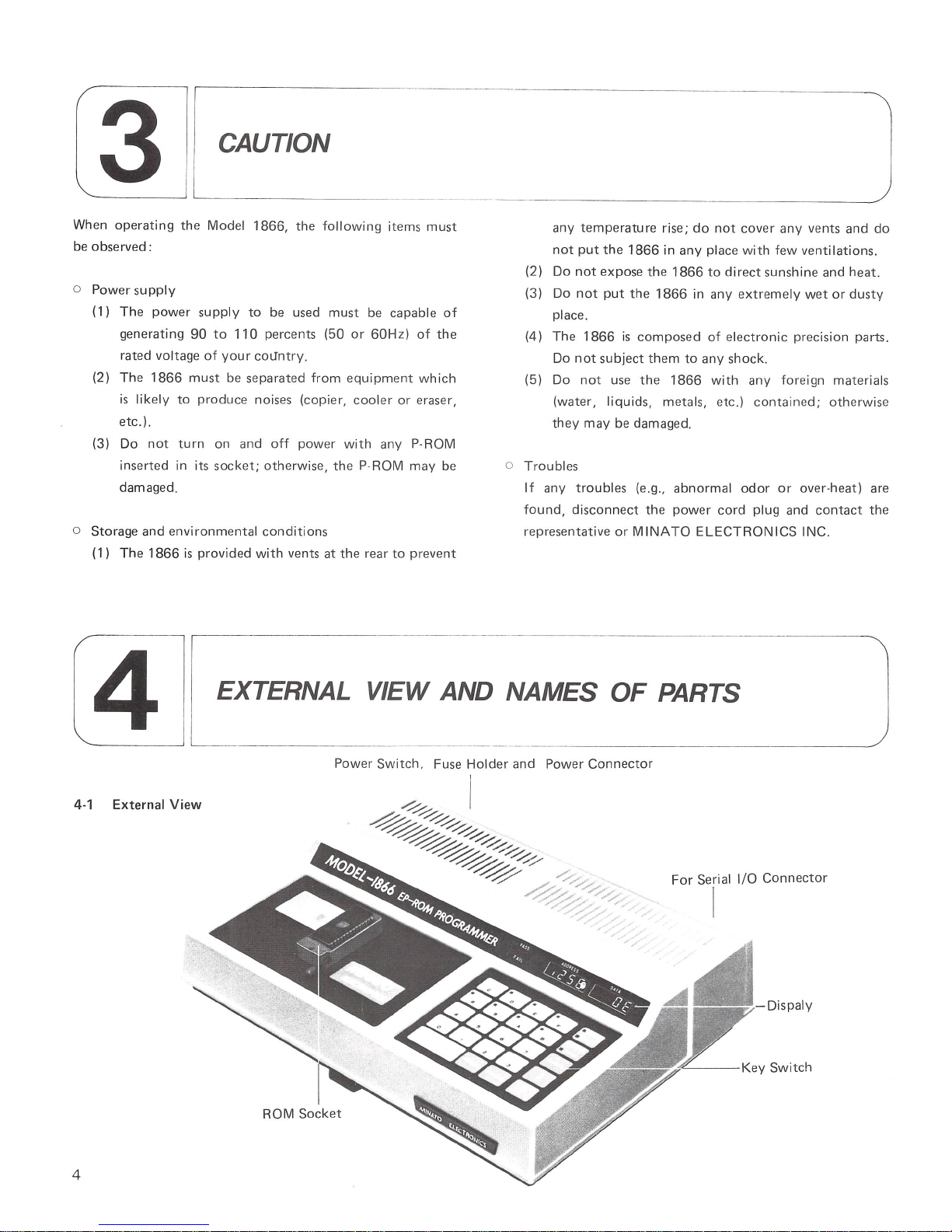
4-1 External View
4
Power
Switch
. Fuse Holder and Power
Connector
I
ROM
Socket
~I
~
~
~'r
~/-;:::::>
/~::»
/'
For
Serial
I/O
Connector
I
Dispaly
'<----
Key
Switch
4-2
Display
I
---0
P A
SS
2 1
---0
~
AIL
•
•
Q)
C
® 0
•
•
([J
8
@ 9
15
ADDR
ESS
In'-""'
I
~
'-'
'-,
'-'
•
@ E
•
rID
A
16
17
n A
TA
r
CCLL
I
'-' '-'
L'
'-'
J
•
® F
•
@ B
•
•
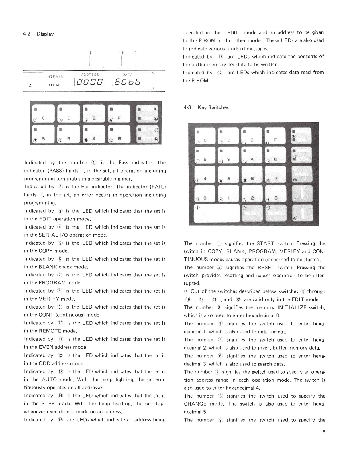
Indicated
by
the
number
CD
is
the
Pass
indicator.
The
indicator
(PASS) lights if, in
the
set,
all
operation
including
programming
terminates
in a
desirable
manner.
Indicated
by
(2;
is
the
Fail
indicator.
The
indicator
(FAI L)
lights if, in
the
set,
an
error
occurs
in
operation
including
programming.
Indicated
by
(3
is
the
LED
which
indi
cates
that
the
set
is
in
the
EDIT
operation
mode.
Indicated
by
r4
)
is
the
LED
which
indicates
that
the
set
is
in
the
SERIAL
I/O
operation
mode
.
Indicated
by ® is
the
LED
which
indicates
that
the
set
is
in
the
COpy
mode.
Indicated
by ® is
the
LED
which
indicates
that
the
set
is
in
the
BLANK
check
mode.
Indicated
by
(
7)
is
the
LED
which
indicates
that
the
set
is
in
the
PROGRAM
mode.
Indicated
by ~ is
the
LED whi
ch indicates
that
the
set
is
in
the
VERIFY
mode
.
Indicated
by ~ is
the
LED
which
indicates
that
the
set
is
in
the
CONT
(continuous)
mode.
Indicated
by
'1Ql
is
the
LED
which
indicates
that
the
set
is
in
the
REMOTE
mode
.
Indicat
ed
by
OJ)
is
the
LED
which
indicates
that
the
set
is
in
the
EVEN
address
mode.
Indicated
by
C11l
is
the
LED whi
ch indicates
that
the
set
is
in
the
ODD
address
mode.
Indicated
by
@
is
the
LED
which
indicates
that
the
set
is
in
the
AUTO
mode.
With
the
lamp
lighting,
the
set
con-
tinuously
operates
on
all
addresses.
Indicated
by
rj]
is
the
LED
which
indicates
that
the
set
is
in
the
STEP
mode.
With
the
lamp
lighting,
the
set
stops
whenever
execution
is
made
on
an
address.
Indicated
by
~
are
LEDs
which
indicate
an
address
being
operated
in
the
EDIT
mode
and
an
address
to
be given
to
the
P-ROM
in
the
other
modes. These LEDs
are
also
used
to
indicate
various
kinds
of
messages.
Indicated
by 16)
are
LEDs
which
indicate
the
contents
of
the
buffer
memory
for
data
to
be
written.
Indicated
by
M)
are
LEDs
which
indicates
data
read
from
the
P-ROM.
4-3
Key
Switches
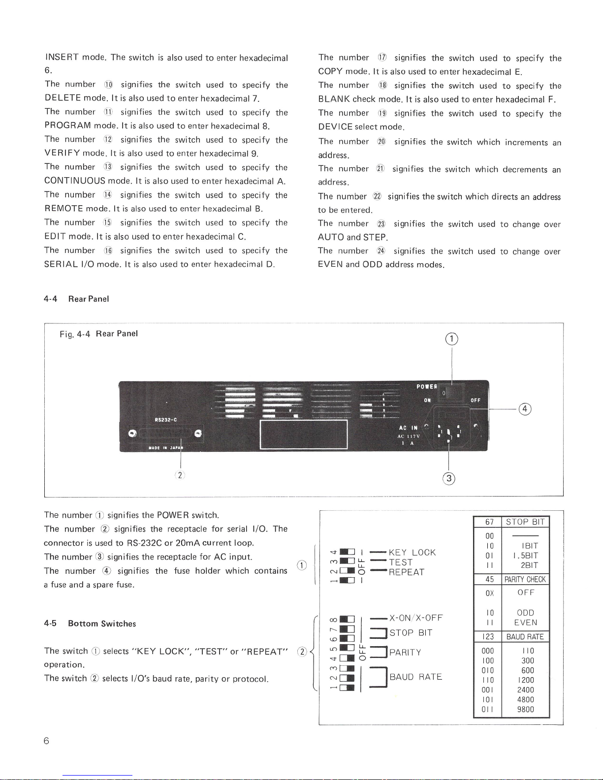
The
number
(1; signifies
the
START
switch.
Pressing
the
switch
in
COPY,
BLANK,
PROGRAM,
VERIFY
and
CON-
TI
NUOUS
modes
causes
operation
concerned
to
be
started.
The
number
(2)
signifies
the
RESET
switch.
Pressing
the
switch
provides
resetting
and
causes
operation
to
be
inter-
ru
pted.
o
Out
of
the
switches
described
below,
switches ~ through
I
OJ
,
I
~
,
21
,and
n
are
valid
only
in
the
EDIT
mode.
The
number
3
~
signifies
the
memory
INITIALIZE
switch,
which
is
also
used
to
enter
hexadecimal
O.
The
number
4) signifies
the
switch
used
to
enter
hexa-
decimal
1,
which
is
also
used
to
data
format.
The
number
(5) signifies
the switch
used
to
enter
hexa-
decimal
2,
which
is
also
used
to
invert
buffer
memory
data.
The
number
(6)
signifies
the
switch
used
to
enter
hexa-
decimal
3,
wh
ich
is
also
used
to
search
data.
The
number
(j)
signifies
the
switch
used
to
specify
an
opera
-
tion
address
range
in
each operation
mode.
The
switch
is
also
used
to
enter
hexadecimal
4.
The
number
® signifies
the
switch
used
to
specify
the
CHANGE
mode.
The
switch is
also
used
to
enter
hexa-
decimal
5.
The
number
® signifies
the
switch
used
to
specify
the
5
INSERT
mode.
The
switch
is also used
to
enter
hexadecimal
6.
The number
@ signifies
the
switch
used
to
specify
the
DELETE
mode.
It
is
also used
to
enter
hexadecimal
7.
The number
6Jl
signifies
the
switch
used
to
spec
ify
the
PROGRAM
mode.
It
is
also
used
to
enter
hexadecimal
8.
The
number
(i?)
signifies
the
switch
used
to
specify
the
VERIFY
mode.
It
is also
used
to
enter
hexadecimal
9.
The
number
@ signifies
the
switch
used
to
specify
the
CONTINUOUS
mode.
It
is
also
used
to
enter
hexadecimal
A.
The
number
(j];
sign ifies
the
switch
used
to
specify
the
REMOTE
mode.
It is al
so
used
to
enter
hexadecimal
B.
The number
@ signifies
the
switch
used
to
specify
the
EDIT
mode
. It
is also
used
to
enter
hexadecimal
C.
The number
@ signifies
the
switch
used
to
specify
the
SERIAL I/O
mode.
It
is
also
used
to
enter
hexadecimal
D.
4-4
Rear
Panel
The
number
@ signifies
the
switch
used
to
specify
the
COpy
mode.
It
is
also used
to
enter
hexadecimal
E.
The
number
@ signifies
the
switch
used
to
specify
the
B LAN K
check
mode.
It is
also
used
to
enter
hexadeci
mal F.
The
number
Ci]l
signifies
the switch
used
to
spec
ify
the
DEVICE
select
mode.
The
number
(?~
signifies
the
switch which
increments
an
address.
The
number
® signifies
the
switch
which
decrements
an
address.
The
number
® signifies
the
switch
which
directs
an address
to
be
entered.
The
number
® signifies
the switch
used
to
change
over
AUTO
and
STEP.
The
number
® signifies
the
sw it
ch
used
to change
over
EVEN
and
ODD
address
modes.
,--
------------------------
-_.
--
-------------
-
--
-----
---,
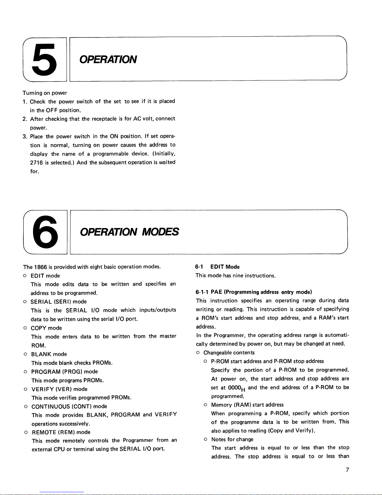
Fig.
4-4
Rear
Panel
L-
____
_
____
________
.__
____
__________
__ _ __
_
The
number
CD
signifi es
the
POWER
switch.
Th e
number
@ signifies
the
receptacle
for
seria l I/O.
The
connector
is
used
to
RS-232C
or
20mA
current
loop.
The
number
® signifies
the
receptac
le
for
AC
input.
The number
® signifies
the
fuse
holder
which
contains
a fuse
and a spare
fuse.
4-5
Bottom
Switches
Th e
switch
CD
sel
ects
"KEY
LOCK",
"TEST"
or
"REPEAT"
(2)
operation
.
The
switch @ selects
I/O's
baud
rate,
parity
or
protocol.
",".:::J
I - KE Y LOCK
(Y).:::J
t:::
-
TEST
Nc:::.I 0
-REPEAT
--=:1
I
co.:]
I
-X-ON
/
X-OFF
:;:s
::::J
STOP
BIT
en.:]
t:::
=:J
PARITY
","C=-o
:§51
~BAUD
RATE
CD
67
STOP BIT
00
---
10 IBIT
01
1.5BIT
II
2BIT
45
PARITY
CHECK
OX
OFF
10
ODD
II
EVEN
123
BAUD
RATE
000
110
100
300
010
600
110
1200
001
2400
101
4800
011
9800
~_~
JJ
6
5
OPERATION
Turning
on
power
1. Check
the
power switch
of
the
set
to
see if it
is
placed
in
the
OFF
position.
2.
After
checking
that
the
receptacle
is
for AC volt,
connect
power.
3.
Place
the
power switch
in
the
ON
position.
If
set
opera-
tion
is
normal,
turning
on
power
causes
the
address
to
display
the
name
of
a programmable device. (Initially,
2716
is
selected.) And the
subsequent
operation
is
waited
for.
/6
OPERATION
MODES
,~------~~----------------------------------------------------------------~
The
1866
is
provided with eight basic
operation
modes.
o EDIT
mode
This
mode
edits
data
to
be
written
and
specifies an
address
to
be programmed.
o
SERIAL
(SERI)
mode
This
is
the
SERIAL
I/O
mode
which
inputs/outputs
data
to
be
written
using
the
serial I/O port.
o
COpy
mode
This
mode
enters
data
to
be
written
from
the
master
ROM.
o BLANK
mode
This
mode
blank checks PROMs.
o PROGRAM (PROG)
mode
This
mode
programs PROMs.
o
VERIFY
(VER)
mode
This
mode
verifies programmed PROMs.
o CONTINUOUS (CONT)
mode
This
mode
provides BLANK, PROGRAM and
VERIFY
operations successively.
o REMOTE (REM)
mode
This
mode
remotely controls
the
Programmer from an
external
CPU
or
terminal using
the
SERIAL I/O port.
6-' EDIT Mode
This
mode
has nine instructions.
6-'-'
PAE (Programming address entry mode)
Th
is
instruction specifies an
operating
range during
data
writing
or
reading. This instruction
is
capable
of
specifying
a ROM's
start
address and
stop
address, and a RAM's
start
address.
In
the
Programmer,
the
operating address range
is
automati-
cally determined by power
on,
but
may be changed
at
need.
o Changeable
contents
o P-ROM
start
address
and
P-ROM
stop
address
Specify
the
portion
of
a P·ROM
to
be programmed.
At
power
on,
the
start
address
and
stop
address are
set
at
OOOOH
and
the
end
address
of
a P-ROM
to
be
programmed.
o Memory (RAM)
start
address
When programming a P-ROM, specify which portion
of
the
programme
data
is
to
be
written
from. This
also applies
to
reading (Copy and Verify).
o Notes
for
change
The
start
address
is
equal
to
or less than
the
stop
address.
The
stop
address
is
equal
to
or
less
than
7
P-ROM's end address. Unless
the
above requirements
are met,
"E-4"
is
displayed, when
"START"
is
pressed.
Presented below
is
the
procedure.
(1) Press "EDIT".
(2)
Press
"PAE".
(PAE
refers
to
Erogram Address s.ntry.)
(3)
Enter a programming start address
(P-ROM
start address)
in
a hexadecimal number consisting
of
four digits .
.If
no change
is
required, press
"t"
to
proceed
to
the
step (5).
(4) Press "A-ENT".
(5) Enter a programming
stop
address
(P-ROM
stop address)
in
a hexadecimal number consisting
of
four digits.
If
no change
is
required, press
"t"
to
proceed
to
the
step (7).
(6)
Press "A-ENT".
(7)
Enter a memory's (RAM's) start address
in
a hexa-
decimal number consisting
of
four digits.
If
no
change
is
required, press
"t".
"END"
is
displayed and
all
opera-
tion terminates.
(8)
If
"A-ENT"
is
pressed,
"END"
is
displayed and
all
operation terminates.
Examples
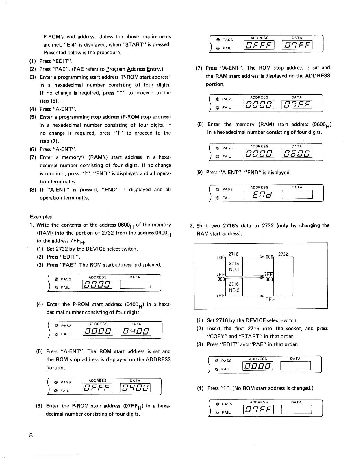
1. Write
the
contents of
the
address
0600H of
the
memory
(RAM) into
the
portion
of
2732 from the address
0400
H
to
the
address
7FF
H
-
8
(1)
Set
2732
by
the
DEVICE select switch.
(2) Press
"EDIT".
(3) Press
"PAE".
The
ROM
start address
is
displayed.
@ PASS
ADDRESS
100001
DATA
@
FAIL
(4) Enter the
P-ROM
start
address (0400H)
in
a hexa-
decimal number consisting
of
four digits.
@ PASS
ADDRESS
DATA
IDDDDI ID'-IDD I
@
FAIL
(5)
Press
"A-ENT". The
ROM
start
address
is
set
and
the
ROM
stop
address
is
displayed on the ADDRESS
portion.
@ PASS
ADDRESS
DATA
IDFFFI
ID'-IDDI
@
FAIL
(6)
Enter the
P-ROM
stop
address (07FFH)
in
a hexa-
decimal number consisting
of
four digits.
@ PASS
ADDRESS
DATA
@
FAIL
IDFFFI
ID'7FFI
(7) Press "A-ENT". The
ROM
stop
address
is
set and
the
RAM
start
address
is
displayed on the ADDRESS
portion.
@ PASS
ADDRESS
DATA
IDDaDI
ID'7FFI
@
FAIL
(8)
Enter
the
memory (RAM)
start
address (0600H)
in
a hexadecimal number consisting
of
four digits.
@ PASS
ADDRESS
@
FAIL
DATA
W5DDl
(9) Press "A-ENT".
"END"
is
displayed.
@ PASS
ADDRESS
DATA
@
FAIL
2. Shift
two
2716's data
to
2732 (only by changing the
RAM
start address).
000
2716
__
......
;.
000
2732
§
716
NO.1
NO.2
7FF
==:::::::::i~~7FF
000[;]716
800
7 F F
...
L---_----'
FFF
(1)
Set
2716
by the DEVICE select switch.
(2) Insert
the
first 2716 into
the
socket, and press
"COPY" and
"START"
in
that
order.
(3)
Press
"EDIT"
and "PAE"
in
that
order.
@ PASS
@
FAIL
ADDRESS
100001
DATA
(4)
Press
"t".
(No
ROM
start address
is
changed.)
ADDRESS
DATA
@ PASS
ID'7FFI
@
FAIL
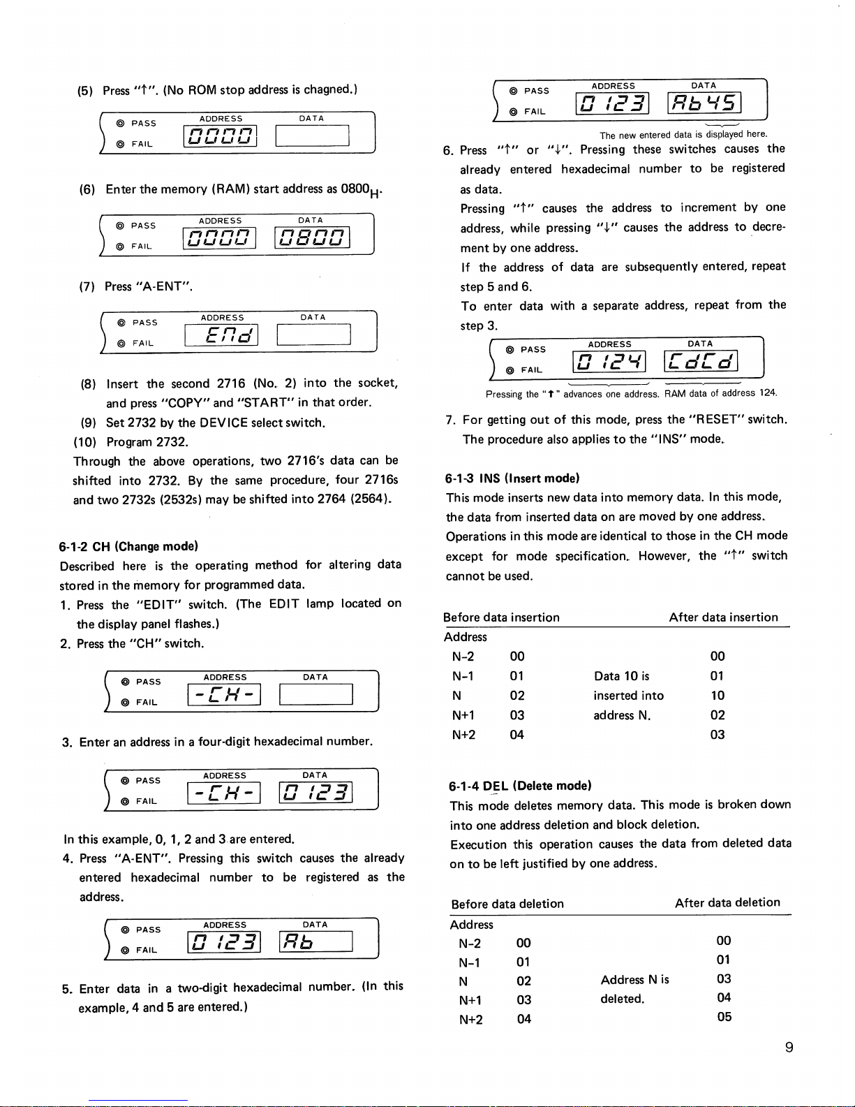
(5) Press
"t".
(No
ROM
stop
address
is
chagned.)
@ PASS
DATA
@
FAIL
(6) Enter the memory (RAM) start address
as
0800
H
.
@ PASS
ADDRESS
DATA
@
FAIL
(7)
Press"
A-ENT".
DATA
@
FAIL
ADDRESS
End]
@ PASS
(8) Insert the second 2716
(No.2)
into
the
socket,
and press "COPY" and
"START"
in
that
order.
(9)
Set
2732
by
the
DEV
ICE
select switch.
(10) Program 2732.
Through the above operations,
two
2716's
data
can be
shifted into 2732.
By
the same procedure, four 2716s
and
two
2732s (2532s) may be shifted into
2764
(2564)_
6-1-2
CH
(Change mode)
Described here
is
the
operating method for altering
data
stored
in
the
memory for programmed data.
1. Press the
"EDIT"
switch. (The EDIT lamp located
on
the
display panel flashes.)
2. Press the
"CH"
switch.
@ PASS
ADDRESS
DATA
@
FAIL
I-Ch'-I
3. Enter an address
in
a four-digit hexadecimal number.
@ PASS
ADDRESS
DATA
I-Ch'-I
10
/231
@
FAIL
In
this example,
0,1,2
and 3 are entered_
4. Press "A-ENT". Pressing this switch causes the already
entered hexadecimal number
to
be registered
as
the
address.
@ PASS
ADDRESS
DATA
10
/231
IRb
@
FAIL
5_
Enter data
in
a two-digit hexadecimal number_
(In
this
example,4
and 5 are entered.)
@ PASS
ADDRESS
DATA
10
/231
IRb
'-151
@
FAIL
'----v--'
The
new
entered data
is
displayed here.
6. Press
"t"
or
".j.".
Pressing these switches causes
the
already entered hexadecimal number
to
be registered
as
data.
Pressing
"t"
causes the address
to
increment by one
address, while pressing
"t"
causes
the
address
to
decrement by one address.
If
the address
of
data are subsequently entered, repeat
step 5 and 6.
To enter data with a separate address, repeat from
the
step 3.
@ PASS
ADDRESS
DATA
10
/2'-11
Ic
dC
dl
@
FAIL
~~
Pressing
the"
t
..
advances
one
address. RAM data of address 124.
7. For getting
out
of
this mode, press the
"RESET"
switch.
The procedure also applies
to
the
"INS"
mode.
6-1-3
INS
(Insert mode)
This mode inserts new data into memory data.
In
this mode,
the data from inserted data on are moved by one address.
Operations
in
this mode are identical
to
those
in
the
CH
mode
except
for mode specification. However,
the
"t"
switch
cannot
be used.
Before data insertion
After data insertion
Address
N-2
00
00
N-1
01
Data
10
is
01
N
02
inserted into
10
N+1
03
address
N.
02
N+2
04
03
6-1-4 DEL (Delete mode)
This mode deletes memory data. This mode
is
broken down
into one address deletion and block deletion.
Execution this operation causes the
data
from deleted data
on
to
be left justified by one address.
Before data deletion After data deletion
Address
N-2
00
00
N-1
01
01
N
02
Address N
is
03
N+1
03
deleted.
04
N+2
04
05
9
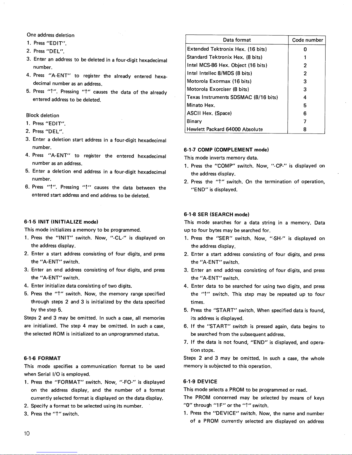
One address deletion
1. Press
"EDIT".
2. Press
"DEL".
3. Enter an address
to
be deleted
in
a four-digit hexadecimal
number.
4. Press
"A-ENT"
to
register
the
already entered hexa-
decimal number
as
an address.
5. Press
"t".
Pressing
"t"
causes
the
data
of
the
already
entered address
to
be deleted.
Block deletion
1. Press
"EDIT".
2. Press
"DEL".
3.
Enter a deletion
start
address in a four-digit hexadecimal
number.
4. Press
"A-ENT"
to
register
the
entered hexadecimal
number
as
an address.
5. Enter a deletion end address
in
a four-digit hexadecimal
number.
6. Press
"t".
Pressing
"t"
causes
the
data
between
the
entered
start
address and end address
to
be deleted.
6-1-5 INIT (INITIALIZE mode)
This mode initializes a memory
to
be programmed.
1.
Press
the
"INIT"
switch. Now, "-CL-"
is
displayed on
the
address display.
2. Enter a
start
address consisting
of
four digits, and press
the
"A-ENT"
switch.
3; Enter an
end
address consisting
of
four
digits, and press
the"
A-ENT" switch.
4. Enter initialize
data
consisting
of
two
digits.
5. Press
the
"t"
switch. Now,
the
memory range specified
through steps 2 and 3
is
initialized by
the
data
specified
by
the
step 5.
Steps 2 and 3 may
be
omitted.
In
such a case,
all
memories
are initialized. The
step
4 may be
omitted.
In
such a case,
the
selected
ROM
is
initialized
to
an unprogrammed status.
6-1-6 FORMAT
This mode specifies a communication format
to
be used
when Serial I/O
is
employed.
1.
Press
the
"FORMAT"
switch. Now,
"-FO-"
is
displayed
on
the
address display, and
the
number
of a format
currently selected
format
is
displayed on
the
data
display.
2. Specify a
format
to
be selected using its number.
3.
Press
the
"t"
switch.
10
Data
format
Extended
Tektronix
Hex. (16 bits)
Standard
Tektronix
Hex.
(8
bits)
Intel MCS-86 Hex. Object (16 bits)
Intel Intellec 8/MDS (8 bits)
Motorola Exormax (16 bits)
Motorola Exorciser
(8
bits)
Texas Instruments SDSMAC (8/16 bits)
Minato Hex.
ASCII Hex. (Space)
Binary
Hewlett Packard
64000
Absolute
6-1-7 COMP (COMPLEMENT mode)
This mode inverts memory data.
Code
number
0
1
2
2
3
3
4
5
6
7
8
1. Press
the
"COMP" switch. Now, "-CP-"
is
displayed on
the
address display.
2. Press
the
"t"
switch. On
the
termination
of
operation,
"END"
is
displayed.
6-1-8 SER (SEARCH mode)
This mode searches for a
data
string
in
a memory. Data
up
to
four bytes may be searched for.
1.
Press
the
"SE
R"
switch. Now,
"_SH_"
is
displayed on
the
address display.
2. Enter a
start
address consisting
of
four
digits, and press
the
"A-ENT"
switch.
3. Enter an end address consisting
of
four
digits, and press
the
"A-ENT"
switch.
4.
Enter data
to
be
searched for using
two
digits, and press
the
"t"
switch. This step may be repeated
up
to
four
times.
5. Press
the
"START"
switch. When specified data
is
found,
its address
is
displayed.
6. If
the
"START"
switch
is
pressed again,
data
begins
to
be searched from
the
subsequent
address.
7 _ If
the
data
is
not
found,
"END"
is
displayed, and opera-
tion
stops.
Steps 2 and 3 may
be
omitted
..
In
such a case,
the
whole
memory
is
subjected
to
this operation.
6-1-9 DEVICE
This mode selects a
.PROM
to
be programmed
or
read
..
The PROM concerned may be selected
by
means
of
keys
"0"
through "1
F"
or
the
"t"
switch.
1. Press
the
"DEVICE"
switch. Now,
the
name and number
of
a PROM currently selected are displayed
on
address
and
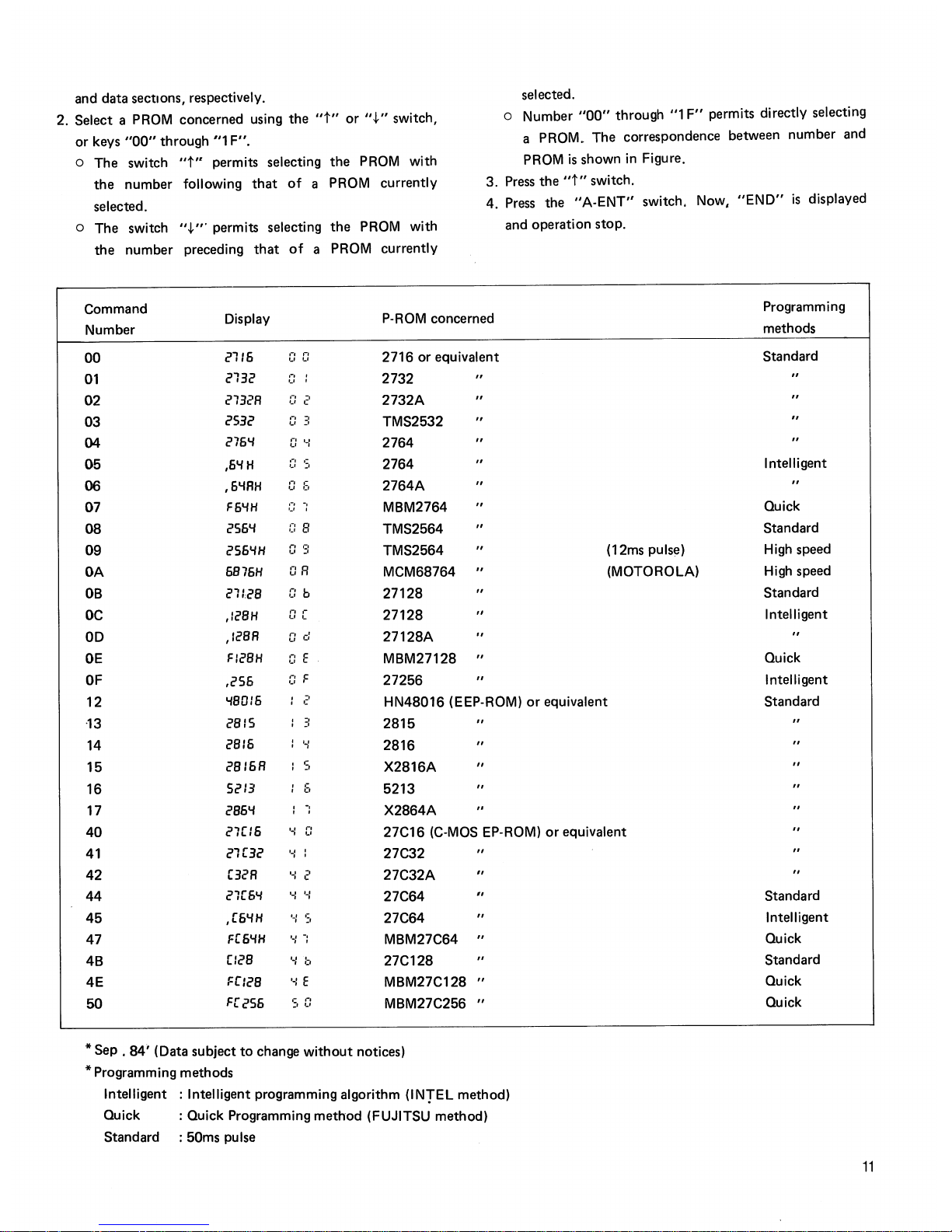
data sections, respectively.
2. Select a PROM concerned using the
"t"
or
".j."
switch,
or keys
"00"
through
"1
F".
a The switch
"t"
permits selecting the
PROM
with
the number following
that
of
a PROM currently
selected.
a The switch ".j.'" permits selecting the
PROM
with
the number preceding
that
of
a PROM currently
Command
selected.
a Number
"00"
through "1
F"
permits directly selecting
a PROM
..
The correspondence between number
and
PROM
is
shown in Figure.
3.
Press
the
"t"
switch.
4.
Press
the
"A-ENT"
switch, Now,
"END"
is
displayed
and
operation stop.
Number
Display
P-ROM concerned
Programming
methods
00
2116
I-I
"
2716
or
equivalent
'.' '-'
01
2132
,-,
,
2732
u
,
02
2132R
,-,
-,
'.' c
2732A
03
2532
"
-,
'-'
:'
TMS2532
04
276"1
.,
I'
~,
.,
2764
05
,6"1H
'-I
,-
'-'
:.
2764
06
,6"1RH
:]
::,
2764A
07
F6"1H
c:
-:
MBM2764
08
256"1
CI
B
TMS2564
09
256"1H
.,
':'
u "
TMS2564
(12ms pulse)
OA
6876H
OR
MCM68764
(MOTOROLA)
DB
21/28
c:
b
27128
OC
,/28H
II
,.
27128
u ~
OD
,128R
o d
27128A
DE
FI28H
c:
E
MBM27128
OF
,256
C:
F
27256
12
"180/6
-,
0:
HN48016 (EEP-ROM)
or
equivalent
·13
28/5
:1
2815
14
2816 ' "
' ,
2816
15
2816R
S
X2816A
"
16 5213
,-
0:,
5213
17
286"1
-:
X2864A
40
27[16
'.:
r,
27C16
(C-MOS
EP-ROM)
or
equivalent
~,
41
21[32
'-I
27C32
42
[32R
.-:
2
27C32A
"
44
21[6"1
y y
27C64
45
,[6"1H
'-:
':,
27C64
47
F[6"1H
'-:
-:
MBM27C64
4B
[/28
'-;
b
27C128
4E
Fr/28
'-:
E
MBM27C128
"
50
F[256
SO
MBM27C256
"
*
Sep , 84'
(Data subject
to
change
without
notices)
* Programming methods
Intelligent : Intelligent programming algorithm
(INTEL
method)
Quick : Quick Programming method (FUJITSU method)
Standard : 50ms pulse
Standard
Intelligent
Quick
Standard
High
speed
High
speed
Standard
Intelligent
Quick
Intelligent
Standard
Standard
Intelligent
Quick
Standard
Quick
Quick
11
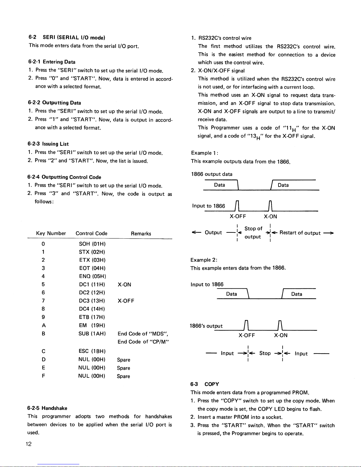
6-2 SERI (SERIAL
I/O
mode)
This mode enters
data
from
the
serial I/O port.
6-2-1 Entering Data
1. Press
the
"SERI"
switch
to
set
up
the
serial I/O mode.
2. Press
"0"
and
"START".
Now, data
is
entered
in
accord-
ance with a selected format.
6-2-2
Outputting
Data
1. Press
the
"SERI"
switch
to
set
up
the serial I/O mode.
2. Press
"1"
and
"START".
Now, data
is
output
in
accord-
ance with a selected format.
6-2-3 Issuing List
1. Press
the
"SER
I" switch
to
set
up
the
serial I/O mode.
2. Press
"2"
and
"START".
Now,
the
list
is
issued.
6-2-4
Outputting
Control Code
1. Press
the
"SE R I" switch
to
set
up
the serial I/O mode.
2. Press
"3"
and
"START".
Now,
the
code
is
output
as
follows:
Key Number
0
2
3
4
5
6
7
8
9
A
B
C
D
E
F
6-2-5 Handshake
Control Code
SOH (OlH)
STX (02H)
ETX (03H)
EOT (04H)
ENG (05H)
DC1(11H)
DC2 (12H)
DC3 (13H)
DC4
(14H)
ETB(17H)
EM
(19H)
SUB
(lAH)
ESC
(1
BH)
NUL
(OOH)
NUL
(OOH)
NUL
(OOH)
Remarks
X-ON
X-OFF
End Code
of
"MDS",
End Code
of
"CP/M"
Spare
Spare
Spare
This programmer adopts
two
methods for handshakes
between devices
to
be applied when
the
serial I/O
port
is
used.
12
1. RS232C's control wire
The first
method
utilizes
the
RS232C's control wire.
This
is
the
easiest
method
for connection
to
a device
which uses
the
control
wire.
2. X-ON/X-OFF signal
This
method
is
utilized when
the
RS232C's control wire
is
not
used,
or
for interfacing with a
current
loop.
This
method
uses an
X-ON
signal
to
request data trans-
mission, and an X-OFF signal
to
stop
data
transmission.
X-ON
and X-OFF signals are
output
to
a line
to
transmit/
receive
data.
This Programmer uses a code
of
"11H" for
the
X-ON
signal, and a
code
of
"13
H
" for
the
X-OFF signal.
Example 1 :
This example
outputs
data from the 1866.
1866
output
data
Data
\ I
Data
Input
to
1866
n n
X-OFF
X-ON
:
Stop
of
.!
<Eo-
Output
-14
, ..... Restart
of
output
__
I
output
I
Example
2:
This example enters data from
the
1866.
Input
to
1866
---,\
Data _
I Data
1866's
output
n
~
X-OFF
X-ON
I I
--
Input
~I
.....
Stop
~I
.....
Input
--
I
I
I
I
6-3 COPY
This mode enters
data
from a programmed PROM.
1. Press
the
"COpy"
switch
to
set
up
the
copy mode. When
the
copy
mode
is
set,
the
COpy
LED begins
to
flash.
2. Insert a master PROM into a socket.
3.
Press
the
"START"
switch. When
the
"START"
switch
is
pressed,
the
Programmer begins
to
operate.
4. After
all
data have been read, the "PASS"
LED
flashes
and the check sum value
*1
is
displayed, and operation
stops.
o The copy mode reads two data from a
PROM
and com-
pares the data with each other
to
detect reading errors.
When
a reading error
is
detected,
the
"FAIL"
LED
flashes and an error message *2
is
displayed, and opera-
tion stops.
o The copy mode does
not
perform "STEP" operation.
In
the copy mode, the address specified
in
the
"PAE"
mode
is
invalid. However, the "RAM START" address
is
valid.
o
In
the
copy mode, the address mode *3
is
valid.
o The order
of
executing steps 1 and 2
is
left
to
the user's
discretion.
*1: See 6-11.
*2: See 6-12.
*3: See 6-9.
6-4
BLANK
This mode checks a PROM's unprogrammed or delete state.
1.
Press
the "BLANK" switch
to
set up the blank mode.
When
the
blank mode
is
set up,
the
BLANK
LED
flashes.
2. Insert a
PROM
into a socket.
3.
Press
the
"START"
switch. Now, operation starts.
When
an error
is
found, its address data
is
displayed and opera-
tion stops.
When
the
"t"
switch
is
pressed, operation
restarts from the next address.
If
the
"START"
switch
is
pressed, operation
is
carried
out
from the start.
4. After the termination
of
checking
all
addresses,
the
"PASS"
LED
lights and operation stops.
o The blank check mode
is
capable of step operation.
o
In
the
blank check mode, every
PAE
is
valid.
o The order of executing steps 1 and
is
left
to
the user's
discretion.
o
In
the
blank check mode, the address mode
is
valid.
6-5 PROG (PROGRAM) Mode
This mode programs a PROM.
1.
Press
the "PROG" switch
to
set
up
the
program mode.
When
the program mode
is
set up, the
"PROG"
LED
flashes.
2. Insert a
PROM
into a socket.
3.
Press
the
"START"
switch. Now, program operation
starts.
4. After
all
addresses have finished being programmed,
the "PASS"
LED
lights and the check sum
is
displayed,
and operation stops.
If
an error
is
found,
the
same pro-
cessing
as
the blank check
is
conducted.
o The program mode, on the termination of programming,
carries
out
the verify check.
o For notes, see 6-4 "BLANK".
6-6 VER (VERIFY) Mode
This mode compares the contents of a programmed
PROM
with those
of
the
RAM
to
check if it has been programmed
normally.
1.
Press
the
"VER"
switch
to
set up
the
verify mode.
When
the verify mode
is
set
up, the
"VER"
LED
flashes.
2. Insert a
PROM
into a socket.
3.
Press
the
"START"
switch. Now, the verify check starts.
4. After the termination of programming
all
addresses, the
"PASS"
LED
lights and the check sum
is
displayed, and
operation stops.
If
an error
is
found,
the
same processing
as
the blank check
is
conducted.
o Verify operation
is
conducted four times,
as
conditions
are varied.
o For the other notes, see 6-4 "BLANK".
6-7 CONT (CONTINUOUS) Mode
This mode provides three operations
of
Blank check, Program and Verify continuously.
For operations, see descriptions for the above three modes.
6-8
REM
(REMOTE) Mode
This mode remotely controls the Programmer from
the
outside using the serial I/O port. For details of this function,
see Chapter 7.
6-9 Address Mode Selection
The Programmer,
in
copy, program and verify operations,
is
capable
of
selecting an address
to
be
programmed.
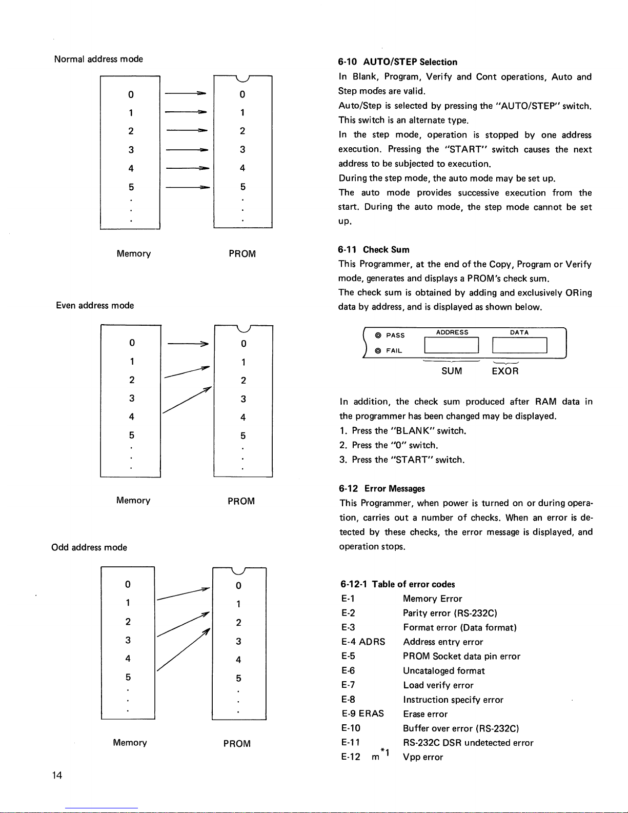
If
the two address mode indication
LEDs
go
out, this signi-
fies
that
the normal address mode has been set up. The
successive memory addresses
will
be programmed.
If
the address mode display
LED
"EVEN" lights, thissigni-
fies
that
the even address mode has been set up. Only
the
even memory addresses
will
be programmed.
If
the
address mode display
LED
"ODD"
lights, this signifies
that
the odd address mode has been set up. Only the odd
memory addresses
will
be
programmed.
13
Normal address
mode
o
2
3
4
5
Memory
Even address mode
o
2
3
4
5
Memory
Odd address mode
14
o
2
3
4
5
Memory
"'"
-
o
2
3
4
5
PROM
o
2
3
4
5
PROM
o
2
3
4
5
PROM
6-10 AUTO/STEP Selection
In
Blank, Program, Verify and
Cont
operations,
Auto
and
Step
modes are valid.
Auto/Step
is
selected by pressing
the
"AUTO/STEP"
switch.
Th
is
switch
is
an alternate type.
In
the
step
mode, operation
is
stopped
by
one
address
execution. Pressing
the
"START"
switch causes
the
next
address
to
be subjected
to
execution.
During
the
step
mode,
the
auto
mode may be set up.
The
auto
mode
provides successive execution from
the
start. During
the
auto mode,
the
step
mode
cannot
be
set
up.
6-11 Check Sum
This Programmer,
at
the
end
of
the
Copy, Program
or
Verify
mode, generates and displays a PROM's check sum.
The check sum
is
obtained by adding and exclusively ORing
data by address, and
is
displayed
as
shown below.
) @ PASS
@
FAIL
ADDRESS
DATA
I I
'-------v------
SUM
EXOR
In
addition,
the
check sum produced after
RAM
data
in
the
programmer has been changed may be displayed.
1. Press
the
"BLANK"
switch.
2. Press
the
"0"
switch.
3.
Press
the
"ST
ART"
switch.
6-12 Error Messages
This Programmer, when power
is
turned
on
or
during opera-
tion, carries
out
a number
of
checks. When an error
is
de-
tected by these checks,
the
error message
is
displayed, and
operation stops.
6-12-1 Table
of
error codes
E-1
E-2
E-3
E-4 ADRS
E-5
E-6
E-7
E-8
E-9 ERAS
E-10
E-11
E-12
*1
m
Memory Error
Parity
error
(RS-232C)
Format
error
(Data format)
Address
entry
error
PROM Socket data pin error
Uncataloged format
Load verify error
Instruction specify error
Erase
error
Buffer over
error
(RS-232C)
RS-232C DSR
undetected
error
Vpp
error

E-13
E-14
E-15
E-16
E-17
n
*2
*1
:
*2:
Vcc error
Reverse insertion error
Other error
Power-on protection error
Time-out error
m refers
to
numerics 1 through 9.
n refers
to
alphabetics A through
D.
The numerics and alphanumerics signify:
1 Vpp 12.5V Pin
23
2
Ditto
Pin
21
3
Ditto
Pin
1
4
Vpp 21.0V
Pin 23
5
Ditto
Pin
22
6
Ditto
Pin 1
7
Vpp 25.0
Pin
23
8
Ditto
Pin
22
9
Ditto
Pin 1
A
Vcc4.75V
B
Vcc 5.00V
C
Vcc 5.25V
D Vcc 6.00V
6-13 Block Operations in Copy, Program, Verify and
Cont
modes
Usually,
the
RAM's addresses used
in
Copy, Program, Verify
and
Cont
modes are specified by the PAE mode.
This mode, irrespective
of
specifications
in
PAE, splits
the
RAM
into several blocks by selected ROM's capacity, num-
bers
the
blocks, and specifies RAM's locations
to
be used
by these numbers.
In
the following example,
the
2764
(8
k-bytes)
is
selected.
0000
0
--------
4000
H
--------
2
--------
3
7FFFH
f
RAM
Block
number
The 1866's
RAM
is
split into
4 blocks composed
of
8K-bytes.
Operations
1. Press
the
"t"
switch.
2. Enter a block number.
3. Press
the
"START"
switch.
The subsequent operations may be carried
out
only by
the
"START"
switch. The set block number may be altered
and this mode may be released by pressing an operation
mode switch such
as
"COPY"
or
the
"RESET"
switch.
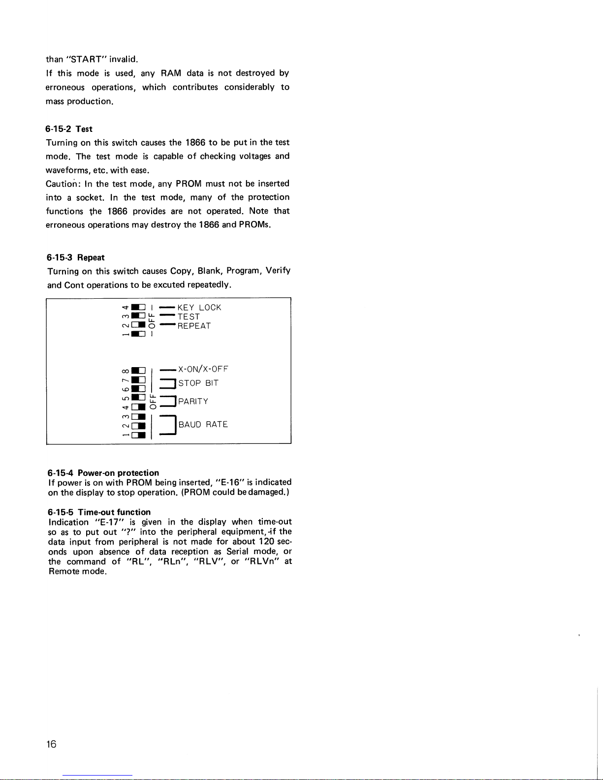
6-14 Setting Serial I/O Mode
The serial I/O's baud rate, parity,
stop
bit
and X-ON/X-OFF
may be selected by means
of
the
bottom
switch.
1. Baud rate selection
The desired baud rate may be selected by switch's three
bits.
67
STOP
BIT
00
--
.".
-=:J
I -
KEY
LOCK
10
IBIT
(Y}-=:Jt:::
-TEST
01
1.5BIT
N~O
-REPEAT
II
2BIT
......
-=:1 I
45
PARITY
CHECK
OX
OFF
co -=:J I -
X-ON/X-OFF
10
ODD
:::s
:::J
STOP
BIT
II
EVEN
123
BAUD
RATE
L.().::J
t:::
::J
PARITY
000
110
.".c=-o
100
300
:i
I
~BAUD
RATE
010 600
110
1200
001
2400
101
4800
011
9800
This Programmer
is
capable
of
setting 110 bauds
to
9600
bauds.
2. Parity selection
The desired parity may
be
selected by switch's bits 4
and 5. Any
of
no
parity, even and
odd
may be selected.
3.
Stop
bit selection
The desired
stop
bit may be selected by switch's bits
6.
and 7. Any
of
1 bit, 1.5 bits and 2 bits may be selected.
4. X-ON/X-OFF selection
X-ON/X-OFF may be selected by
the
switch's bit 8.
6-15 Others
Three operations
of
Key
Lock, Test and Repeat may be
selected by meflns
of
the
bottom
switch.
6-15-1 Key Lock
Turning on this switch makes any switch operations
other
15
than
"START"
invalid.
If
this mode
is
used, any
RAM
data
is
not
destroyed by
erroneous operations, which contributes considerably
to
mass production.
6-15-2 Test
Turning on this switch causes
the
1866
to
be
put
in
the
test
mode. The test mode
is
capable
of
checking voltages and
waveforms, etc. with ease.
Caution:
In
the
test
mode. any
PROM
must
not
be inserted
into a socket.
In
the test mode, many
of
the
protection
functions
the
l866
provides are
not
operated. Note
that
erroneous operations may destroy
the
1866 and PROMs.
6-15-3 Repeat
TUrning on this switch causes Copy, Blank, Program, Verify
and
Cont
operations
to
be
excuted repeatedly.
<:t".::J I - KEY LOCK
M.::J::
-
TEST
Nc::::.O
- REPEAT
.....
.::J
I
oo~
I
-X-ON/X-OFF
:;:s
~
STOP BIT
L.{).:J
tz
::J PARITY
<:t"~O
:§!
I
~BAUO
RATE
6-15-4 Power-on protection
If
power
is
on with
PROM
being inserted, "E-16"
is
indicated
on
the
display
to
stop
operation. (PROM could be damaged. I
6-15-5 Time-out function
Indication
"E-17"
is
given
in
the
display when time-out
so
as
to
put
out
"?"
into the peripheral equipment, -if
the
data
input
from peripheral
is
not
made for
about
120 sec-
onds upon absence
of
data reception
as
Serial mode,
or
the
command
of
"RL",
"RLn",
"RLV",
or
"RLVn"
at
Remote mode.
16
7
REMOTE OPERATION
~~------~~--------------------------------------------------------------~
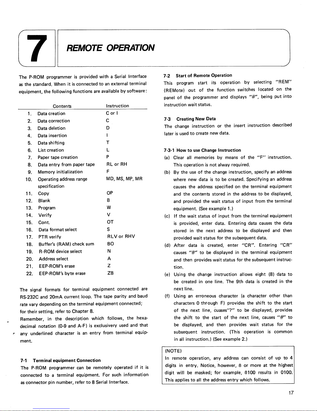
The P-ROM programmer
is
provided with a Serial Interface
as
the
standard. When it
is
connected
to
an
external terminal
equipment,
the
following functions are available by software:
Contents
Instruction
1.
Data creation
C
or
I
2.
Data correction
C
3.
Data deletion
D
4.
Data insertion
5.
Data shifting
T
6.
List creati on
L
7.
Paper tape creation
P
8.
Data
entry
from paper
tape
RL
or
RH
9.
Memory initialization
F
10.
Operating address range
MD,
MS,
Mr,
MR
specification
11.
Copy
OP
12.
Blank
B
13.
Program
W
14.
Verify
V
15. Cont.
OT
16.
Data
format
select S
17.
PTR verify
RLV
or
RHV
18.
Buffer's (RAM) check sum
BO
19.
R-ROM device select
N
20.
Address select
A
21.
EEP-ROM's erase
Z
22.
EEP-ROM's
byte
erase
ZB
The signal formats for terminal
equipment
connected are
RS-232C and
20mA
current
loop. The
tape
parity and baud
rate vary depending on
the
terminal
equipment
connected;
for
their
setting, refer
to
Chapter 8.
Remember, in
the
description which follows,
the
hexa-
decimal notation (0-9 and A-F)
is
exclusivery used and
that
" any underlined character
is
an
entry
from terminal equip-
ment.
7-1
Terminal
equipment
Connection
The P-ROM programmer can be remotely
operated
if it
is
connected
to
a terminal equipment. For such information
as
connector
pin number, refer
to
8 Serial Interface.
7
-2
Start
of
Remote Operation
This program
start
its operation by selecting
"REM"
(REMote)
out
of
the
function switches located
on
the
panel
of
the
programmer and displays
"#",
being
put
into
instruction
wait
status.
7-3 Creating New Data
The change instruction or
the
insert instruction described
later
is
used
to
create new data.
7-3-1 How
to
use Change Instruction
(a)
Clear
all
memories by means
of
the
"F"
instruction.
This operation
is
not
alway required.
(b)
By
the
use
of
the
change instruction, specify an address
where new
data
is
to
be created. Specifying an address
causes
the
address specified
on
the
terminal
equipment
and
the
contents
stored
in
the
address
to
be displayed,
and provided
the
wait status
of
input
from
the
terminal
equipment. (See example 1.)
(c)
If
the
wait status
of
input
from
the
terminal
equipment
is
provided,
enter
data. Entering data causes
the
data
stored
in
the
next
address
to
be displayed and
then
provided wait status for
the
subsequent data.
(d) After data
is
created,
enter
"CR".
Entering
"CR"
causes
"#"
to
be displayed
in
the
terminal
equipment
and then provides wait status for
the
subsequent instruc-
tion.
(e) Using
the
change instruction allows eight (8) data
to
be
created
in
one line. The
9th
data
is
created
in
the
next
line.
(f)
Using an erroneous character
(a
character
other
than
characters 0
through
F)
provides
the
shift
to
the
start
of
the
next
line,
cuases"?"
to
be
displayed, provides
the
shift
to
the
start
of
the
next
line, causes
"#"
to
be displayed, and
then
provides wait status for
the
subsequent instruction. (This operation
is
common
in
all
instruction.) (See example 2.)
(NOTE)
In
remote operation, any address can consist
of
up
to
4
digits
in
entry. Notice, however, 8
or
more
at
the
highest
digit will be masked;
for
example,
8100
results
in
0100.
This applies
to
all
the
address
entry
which follows.
17

Example
1:
Normal Case
#f
.
Q.QEl
(1) (2) (3)
0000 00-11 00 -22 00-33 00-44 00-55 00-66 00-77 00-88
(4) (5) (6) (6) (6) (6) (6) (6) (6) (6)
0008 00-99
OO-AA
OO-BB
OO-CC
00-00
OO-EE
OO-FF
OO-CR
(6) (6)
(6)
(6) (6) (6) (6)
(7)
(1) Enter "c" which signifies
the
change instruction.
(2) Enter an address
to
be changed (or
to
be created) in
not
more
than
4 digits.
(3) Enter
"CR"
at
the
end
of
the
instruciton.
(4) The specified address
is
displayed.
(5) The
contents
of
the
specified address are displayed.
(6) Enter new data.
(7) After
all
data has been entered,
enter
"CR"
at
the
end.
Example
2:
Where Erroneous Character
is
Entered.
#f.
100 CR
0100 00-11
OO-AA
OO-BG
(1
)
?
(2)
#
(3)
(1)
"G"
is
other
than
characters 0 through F and
is
an
erroneous input.
(2) The shift
to
the
start
of
the
next
line
is
provided and
"?"
is
displayed.
(3) The shift
to
the
start
of
the
next
line
is
provided again,
"#"
is
displayed, and wait status for
the
subsequent
instruction
is
provided.
(Note)
In
that
case,
the
contents
before
an
address
to
which
"BG"
has been entered are changed
as
specified,
while
the
contents
of
the
address
to
which
"BG"
has been entered are
not
changed.
7-3-2 How
to
Use Insert Instruction
(a) Clear
all
memories. (This operation
is
not
always
re-
quired.)
(b) Specifying an address where new
data
is
to
be created
by
the
use
of
the
insert instruction and entering
"CR"
provide
the
shift
to
the
start
of
the
next
line and cause
an stored data
to
be displayed. Enter new data
to
be
created. After entering data,
enter
"SP"
and proceed
to
the
subsequent
address. (See example 3.)
(c) After
all
data has been entered,
enter
"CR"
at
the
end,
which provides
the
shift
to
the
start
of
the
next
line,
18
causes
"#"
to
be displayed, and provides
wait
status
for
the
subsequent
instruction.
(d)
In
entered data,
two
characters before liSP"
or
"CR"
are valid and
the
other
characters are ignored. (See
example
4.)
Example: 3
#J.
.
Q.
~B...
(1) (2) (3)
0000 00
11
22 33 44 55 66 77 88 99
AA
BB
CR
.7""7'-----
------------
----
(4) (5)(6)(5) (7)
(1) Enter
"I"
which signifies
the
insert instruction.
(2) Enter an address
to
be inserted
in
alphanumerics consist-
ing
of
not
more
than
4 digits.
(3) Enter
"CR"
at
the
end
of
the
instruction.
(4) The specified address
is
displayed.
(5) Enter new data.
(6) Enter
"SP"
between data.
(7) After
all
data has been entered,
enter
"CR".
The
contents
of
the
memory after this example has been
executed are:
#!:..QL~
CR
0000 00
11
22 33
44
55 66 77 88 99 AA B B
Example: 4
#l.§.CR
0005 1234 5678
CR
(1) (2)
(1).
(2)
In
both
(1) and (2).
data
is
entered
in
four digits.
Valid data
is
two
characters before
"SP"
and
"CR".
In (1),
"3"
and
"4"
are valid, while,
in
(2).
"7"
and
"8"
are
valid_
The
contents
of
the
memory
after
the
instruction has been
executed are:
#h .
..Q.L£
CR
0000 00 00 00 00 00 34 78 00 00 00 00 00 00 00 00 00
7-4
Modifying Data
The
change instruction "c"
is
used
to
modify data.
The
using
method
is
identical
to
that
described
in
the
subsection
"Creating New Data".
Example:
5
#~.Q!£
CR
0000 00
01
02 03 04 05 06
07
08
09
OA
DB
OC
00
OE
OF
Shown
above are
the
contents
of
the
memory before modifi·
cation.
#f.
D CR
(1) (2)
0000
00-00
OE-CR
(3) (4) (5) (6)
 Loading...