

Page 1

USER’S MANUAL
Model VT7
VISI-TACH® Multi-Functional
Digital Indicator
Page 2

Copyright © 1998 by
Minarik Corporation
All rights reserved. No part of this manual may be reproduced or transmitted in any
form without written permission from Minarik Corporation. The information and technical data in this manual are subject to change without notice. Minarik Corporation
and its Divisions make no warranty of any kind with respect to this material, including, but not limited to, the implied warranties of its merchantability and fitness for a
given purpose. Minarik Corporation and its Divisions assume no responsibility for
any errors that may appear in this manual and make no commitment to update or
keep current the information in this manual.
Printed in the United States of America.
Page 3

Safety Warnings
• This symbol denotes an important safety tip or warning.
Please read these sections carefully prior to performing any of
the instructions contained in that section.
• Have a qualified electrical maintenance technician install,
adjust, and service this equipment. Follow the National
Electrical Code and all other applicable electrical and safety
codes, including the provisions of the Occupational Safety
and Health Act (OSHA) when installing equipment.
• Reduce the chance of an electrical fire, shock, or explosion
by proper grounding, over current protection, thermal protection, and enclosure. Follow sound maintenance procedures.
• The VISI-TACH
®
is isolated from earth ground. Circuit
potentials are at 115 VAC or 230 VAC above earth ground.
Avoid direct contact with the printed circuit board or with
circuit elements to prevent the risk of serious injury or
fatality. Use a non-metallic screwdriver for any necessary
adjustments.
Page 4

ii
Page 5

Contents
Specifications 1
Dimensions 2
General Information 3
Installation 4
General installation information ..................................4
Screwterminalblock..........................................5
Mounting...................................................6
Shielded cable ..............................................7
Connections ................................................8
Programming 9
Slideswitch................................................10
DIP switches ...............................................10
Rotary DIP switches - time base calculations .......................12
Application Examples 15
Mode1tachometermode-example1 ...........................15
Mode1tachometermode-example2 ...........................17
Mode2totalizermode........................................22
Mode3ratemonitormode ....................................24
Mode4ratemonitormode(min-secformat) .......................26
iii
Page 6

Page 7

Specifications
AC Line Voltage
VT7-115 115 VAC +/- 10%, 50/60 Hertz, 5.5 Watts
VT7-230 230 VAC +/- 10%, 50/60 Hertz, 5.5 Watts
Programmable Power Supply Output
5VDC@50mA 50 mA, Regulated Source, +/- 4%
12VDC@25mA 25 mA, Unregulated Source, +/- 20%
Operating Temperature Range 10°C–40°C
Maximum Input Rate 20000 Pulses per Second
Feedback Frequency Range 10 – 20000 Hz
LED Readout Size 0.7 inches
Page 8
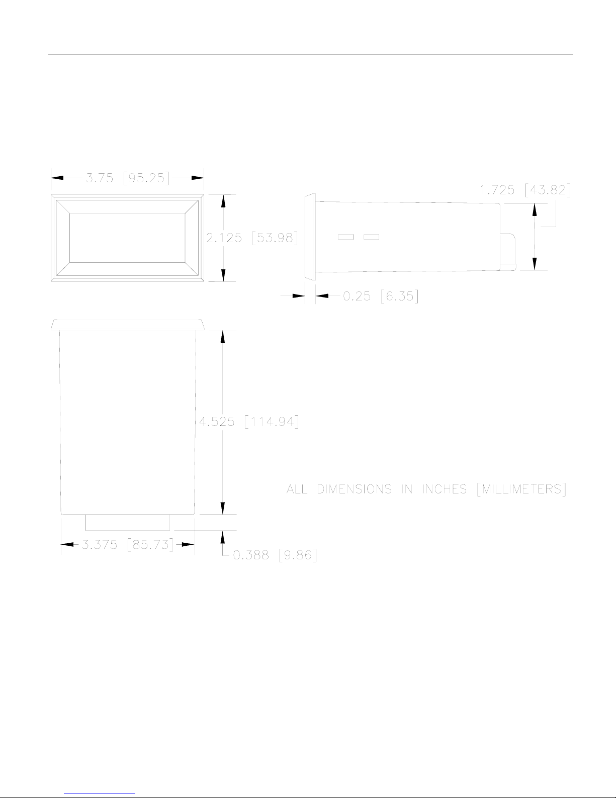
2
Figure 1. Model VT7-115 and Model VT7-230
Multi-Functional Digital Indicator Dimensions
Dimensions
Page 9

3
General Information
Minarik Corporation’s VISI-TACH®models VT7-115 and
VT7-230 provide a means for monitoring the speed of rotating shafts using a digital velocity transducer. Speed transducers such as magnetic pickup, optical encoders or hall effect
sensors convert motor speed into a small signal frequency
which is supplied to the VT7.
The VT7 is a multi-functional device and can be programmed
for use as a tachometer for display of revolutions per minute,
feet per minute, etc. It can also be used as a totalizer, a rate
monitor with a display of an inverse frequency, or a rate monitor with a time format in hours and minutes, or minutes and
seconds.
The unit is programmable using a series of switches, located
under the rear panel access cover. The variables programmed
using these switches are the power supply (5 or 12 VDC), the
type of feedback (magnetic pickup or optical encoder), decimal point location, and the mode the unit will operate in. The
rotary switches program the time base in seconds. Detailed
explanations of each one of these items follow in the programming section of this manual (page 9).
Page 10

4
Installation
General installation information
The VT7 components are sensitive to electrostatic fields.
Avoid contact with the circuit board directly.
Protect the VT7 from dirt and moisture. Provide adequate
clearance for wiring and programming. This takes place at the
back of the unit.
Mount the VT7 away from other heat sources. Operate
within the specified ambient operating temperature range.
The operating temperature range for the VT7 is 10ºC
through 40ºC.
Prevent loose connections by avoiding excessive vibration of
the VT7.
Page 11
5
Installation
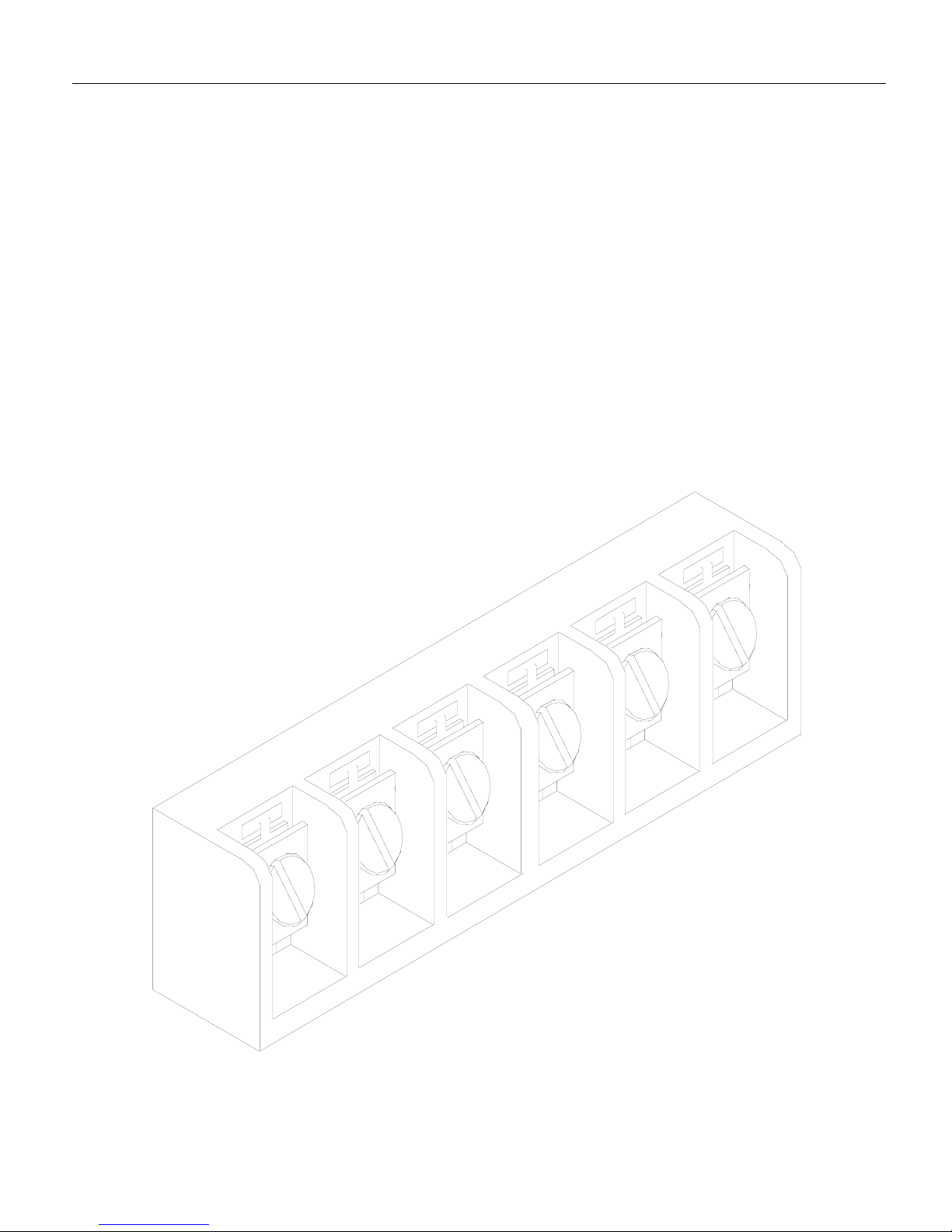
Screw terminal block
Connections to Minarik’s VT7 digital indicator are made to a
screw terminal block. The screw terminal block has a similar
connection style to the one shown below.
Using a screwdriver, turn the terminal block screw counterclockwise to open the wire clamp. Insert stripped wire into the
wire clamp. Turn the terminal block screw clockwise to clamp
the wire.
Fig. 2. Screw Terminal Block
Page 12

6
Installation
Mounting
1. Cut a rectangular opening 1-25/32 inches [45mm] high by
3-3/8 inches [86mm] wide in your panel.
2. Unscrew the two mounting bracket screws until the threaded end is almost flush with the threaded bushing.
3. Place the VISI-TACH®through the panel opening and
install the mounting bracket by engaging the two hooks on
each bracket into the two slots on each side of the unit, with
the threaded end of the screws towards the back of the
panel.
4. Screw the two mounting bracket screws in until they “bite”
into the rear of the panel. The screws should be tight
enough to prevent the VISI-TACH®from moving, but do
NOT over tighten the screws or you may damage your
panel.
Page 13

7
Installation
Shielded cable
Use shielded cable when logic lines are longer than 18 inches
(475 mm). Logic lines of this length act as an antenna and can
pick up noise from other devices or other ground wires, or
voltage from power lines that can cause erratic operation.
Attach the shield to the COM terminal on the back of the VT7
or the pickup source only.
It may be necessary to earth ground one end of the shielded
cable. Do not earth ground both ends of the shield.
Page 14
Connections
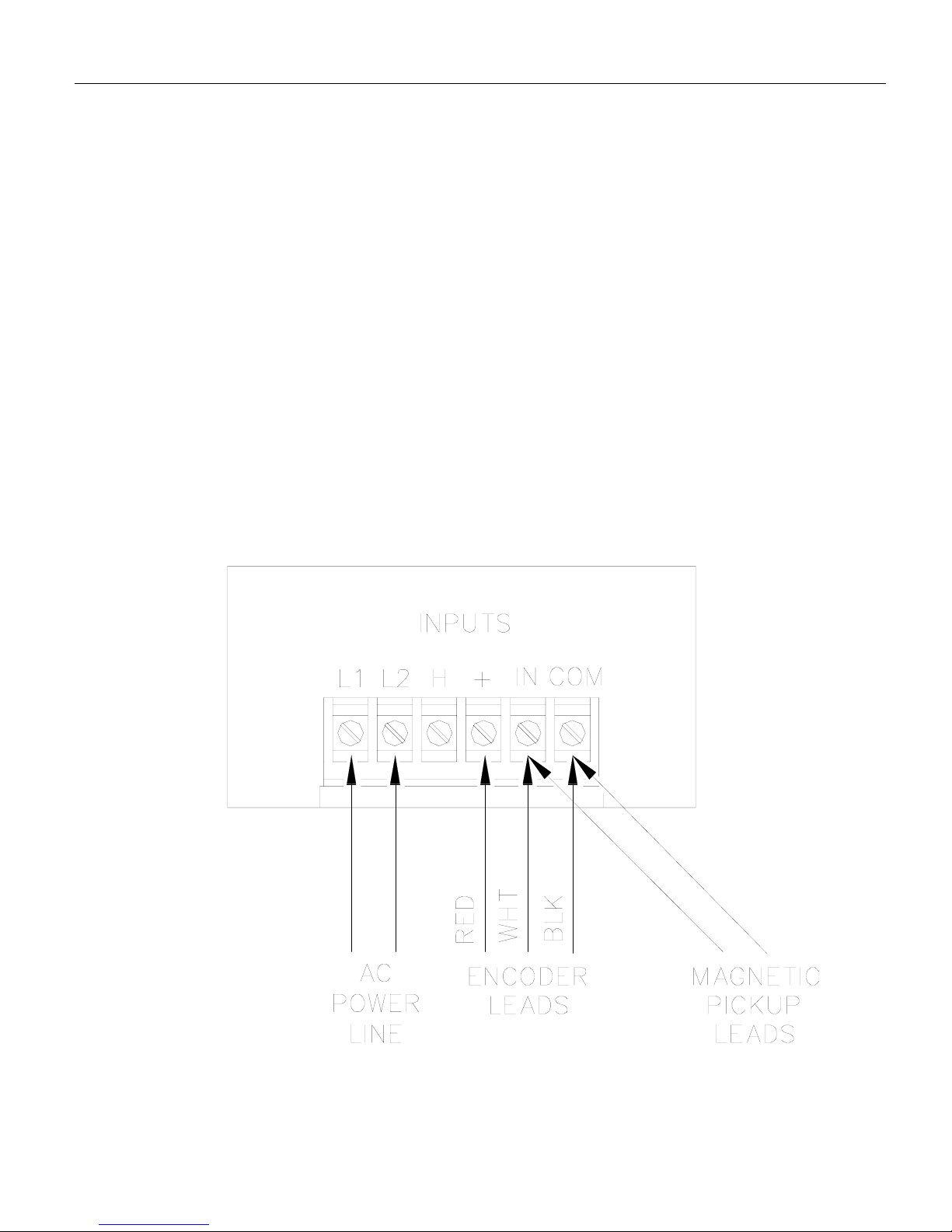
1. Connect the AC power line input on terminals L1 and L2.
This voltage is 115 VAC for the VT7-115 and 230 VAC for
the VT7-230.
2. Connect the pickup, encoder or transducer on the terminals
as indicated in the drawing below.
IMPORTANT! To prevent possible interference do NOT
run pickup, encoder, or transducer cable in same conduit
as the AC line.
Installation
8
Fig. 3. Connection Diagram
Page 15

9
Programming
The VT7 may be programmed before installing it into the
panel, and before connecting to the AC line and the pickup,
encoder or transducer, or after the entire system is set up. For
easier handling, it is usually more convenient to program the
VT7 before it is set in the panel.
For access to the programming switches, remove the two
screws holding the rear cover to the case and remove the
cover. The switches are illustrated in Figure 4.
Fig. 4. VT7 Programming Switches
Page 16

Programming
10
DIP switches
To change the position of the DIP switches use a small screwdriver to push the DIP to the desired position. The DIP switch
block has a similar construction style to one shown below
(Figure 6). In the figure, the DIP switches are set for:
optical encoder (1 on and 2 off),
decimal point 00.00 (3 off, 4 on,and 5 off) ,
and tachometer mode (6 and 7 off).
Slide switch
The position of the slide switch determines the power supply output. Set
the slide switch to +5 or +12VDC to
power an optical encoder. For accuracy and current output of this
power supply see the specifications on page 1.
Fig. 6. VT7 DIP Switches
Fig. 5. VT7 Power
Supply Slide Switch
Page 17

11
Programming
Feedback type. DIP switches 1 and 2 are dependent upon
which type of feedback has been selected. See the table
below for the settings.
Decimal point selection. DIP switches 3, 4 and 5 determine
where the decimal point will light in the display. See the
table below for the settings. Only one switch may be on at
any time.
Mode selection. To select the mode in which VT7 will operate, use DIP switches 6 and 7.
Mode1isthetachometer mode (set 6 OFF and 7 OFF).
The tachometer mode displays the monitored shaft speed or
a multiple of it. The display can be frozen to the last reading
by shorting terminal COM to terminal H.
Feedback Type Switch #1 Switch #2
Magnetic pickup OFF ON
Optical encoder ON OFF
Decimal Location SW#3 SW#4 SW# 5
000.0 ON OFF OFF
00.00 OFF ON OFF
0.000 OFF OFF ON
0000 OFF OFF OFF
Mode of Operation SW#6 SW#7
Tachometer (1) OFF OFF
Totalizer (2) OFF ON
Rate Monitor Mode (3) ON OFF
Rate Monitor Mode (4) ON ON
Page 18

Programming
12
Mode2isthetotalizer mode (set 6 OFF and 7 ON). In this
mode the unit displays continuous count of pulses received
from the speed transducer. The display will turn over to 0000
after either 10,000 pulses have been received from the speed
transducer or the unit has been reset. The display can be reset
to zero by shorting terminal COM to terminal H.
Mode3istherate monitor mode (set 6 ON and 7 OFF). This
mode displays the time in process (or a linear multiple of it) in
seconds. The display in the rate monitor mode is inversely
proportional to the monitored shaft speed.
Mode 4 is the rate monitor mode (min:sec or hour:min for-
mat) (set 6 ON and 7 ON). In this mode the unit displays the
number in time format. This display can be used to read minutes and seconds, or hours and minutes. The display can be
frozen to the last reading by shorting terminal COM to terminal H.
Rotary DIP switches - time base calculations
The programming variable which determines the display reading is called the time base. The time base is the time interval
the VT7 uses to count the pulses from the speed transducer
and issue the result to the display.
The rotary DIP switches program the time base, in seconds,
from 0.01 seconds to 10.00 seconds. Settings of all zeros is
equal to a time base of 10.00 seconds. An explanation of the
time base calculation begins on page 14. The time base is programmed for modes 1, 3, and 4 only.
Page 19

Ideally, the time base should be set between .67 seconds and 2
seconds. If the time base is set below .67 seconds, the display
will update too often and tend to flicker. If the time base is set
greater than two seconds, the display reading will not update
often enough and may lag the actual speed of the application.
To program the rotary switches, use a small screwdriver and
set the pointer mark to the desired number.
The following application variables must be known before calculating the time base (t):
DDN = The desired display number. DDN is the known display value at a certain shaft speed (RPM). It should be 4 digits
and ignore any decimal point present.
RPM = Revolutions per minute of the monitored shaft at the
time when the DDN is known.
PPR = Pulses per revolution of the pickup, encoder or transducer. This is the number of teeth on the pickup wheel or lines
on the optical encoder.
13
Programming
Fig. 7. VT7 Rotary DIP Switches
Page 20

Programming
14
Mode 1 (tachometer mode). The time base (t) is a variable
which scales the RPM of the monitored shaft at the location
of the speed transducer.
The RPM and DDN in the above equation are arbitrary values. Any RPM value may be chosen. The desired display
number for the RPM selected is then determined by the user’s
application.
Mode 2 (totalizer mode). Mode 2 has no time base.
Mode 3 (rate monitor mode). To calculate the time base in
mode 3 use the equation below:
Mode 4 (rate monitor mode (min:sec/hour:min format)).
In this mode we must convert the DDN to an hours and minutes (or minutes and seconds) format. This is done with the
following equation:
DDN = 60X + Y
where X = hours and Y = minutes when operating in the
hours and minutes mode, and X = minutes and Y = seconds
when operating in the minutes and seconds mode.
Calculate the time base with the following equation using the
DDN calculated with the equation above:
250,000
60
(DDN)(RPM)
X
t=
PPR
250,000
60
(DDN)(RPM)
X
t=
PPR
(DDN)(60)
(RPM)(PPR)
t=
Page 21
Application Examples
Mode 1 tachometer mode - example 1
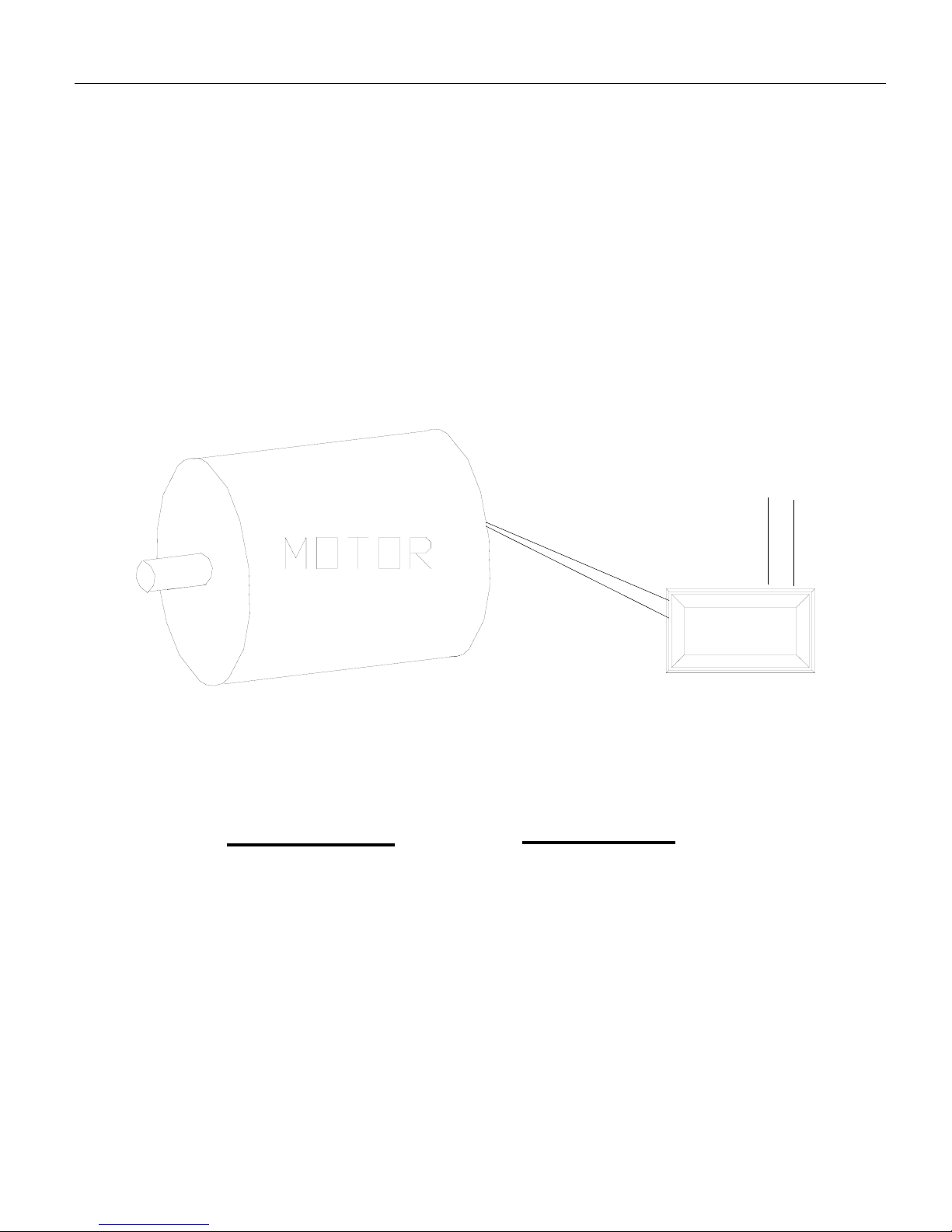
Application. A PK1 magnetic pick up (PPR=30) is mounted
on a motor and is connected to a VT7. The VT7 will display
the speed of the motor directly. Calculate the required time
base.
Solution. Using the equation on page 14 with arbitrary values
of RPM=100, and DDN=100 the time base becomes
2 seconds
This is the standard time base that the factory sets into the
VT7 for shipment. See page 16 for a diagram of the switch
settings for this example.
15
(DDN)(60)
(RPM)(PPR)
t=
(100)(60)
(100)(30)
= =
0100
L1
L2
Page 22
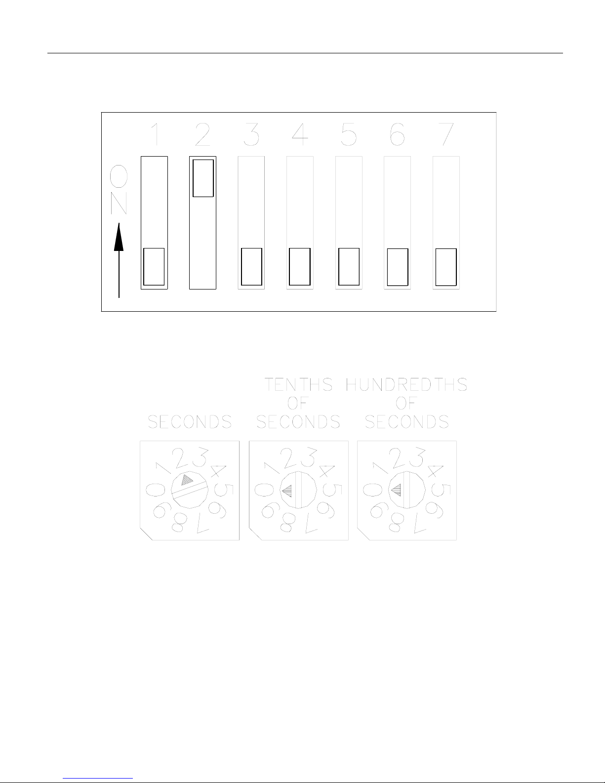
Switch settings - tachometer mode - example one
Application Examples
16
Fig. 8. Tachometer Mode-Example One DIP Switch Settings
Fig. 9. Tachometer Mode Example One
Rotary DIP Switch Settings
Page 23
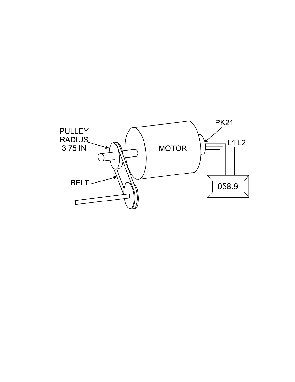
17
Application Examples
Mode 1 tachometer mode - example 2
Application. A PK21-30 encoder (30 lines per revolution) is
monitoring the speed of a motor with a maximum of 1800
RPM. The pulley on the motor has a radius of 3.75 inches.
The user wishes to have the VT7 display the speed of a belt,
which is mounted on the pulley, in feet per second.
Find:
a) The required time base (t).
b) The error due to rounding the time base.
c) The display range in feet per second if the motor speed
ranges from 60 to 1800 RPM.
d) A method for lowering the error.
Solution-a. Start by obtaining a conversion factor between
motor speed in RPM to belt speed in feet per second. Use an
arbitrary speed of 1 RPM for the calculation.
Page 24

18
Application Examples
= .0327 feet per second
Use the equation on page 14 to calculate the time base:
=.06545 seconds
= .07 seconds rounded
Solution-part b. The error is calculated as follows:
= 6.95%
1 revolution
minute
1 RPM =
1rev
minute
1 RPM =
2(π)(r)
minute
X
60 sec.
1min
X
12 inches
1 foot
X
1rev
minute
1 RPM =
minute
60 sec.
1min
12 inches
1 foot
2(3.14)(3.75)
X
X
X
(DDN)(60)
(RPM)(PPR)
t=
rounded value - original value
original value
% error =
(.0327)(60)
(1)(30)
=
X
0.06545
X
0.07 – 0.06545
100
=
100
Page 25

Solution-part c. To determine the display range calculate the
minimum(min) and maximum(max) speed in feet per second:
1 RPM = 0.0327 ft./sec.
Minspeed=30RPM
= 0.98175 feet/second or about 1 foot per second.
Max speed = 1800 RPM
=58.905 feet/second or about 59 feet per second.
This means the display will range from about 0001 to 0059
feet per second.
Solution-part d. The error due to rounding may be decreased
by increasing the display value by a factor of 10 and introducing a decimal point. To do this set DIP switch DP1 on. The
VT7 will read a speed of 10 feet per second as 10.0 feet per
second.
Our new time base becomes:
= 0.654 sec. = 0.65 second (rounded)
19
Application Examples
0.0327 ft./sec.
1 RPM
(30 RPM)
=
X
(DDN)(60)
(RPM)(PPR)
t=
(.327)(60)
(1)(30)
=
0.0327 ft./sec.
1 RPM
(1800 RPM)
X
=
Page 26

Application Examples
20
= .69%
The new display range is:
Min speed = 30 RPM
= 9.818 feet/second or about 10 foot per second.
Max speed = 1800RPM
=589.05 feet/second or about 589 feet per second.
The display will now range from about 0010 to 0589 feet per
second reducing the error by a factor of 10. By placing DIP
switch DP1 on the display will read 001.0 to 058.9.
The error due to rounding could be decreased by further
increasing the DDN by a factor of 10 again and moving the
decimal point (01.00 to 58.90). See page 21 for a diagram of
the switch settings for this example.
rounded value - original value
original value
% error =
X
0.6545
X
0.65 – 0.6545
100
=
0.327 ft./sec.
1RPM
(30 RPM)
X
0.327 ft./sec.
1RPM
(1800 RPM)
X
=
=
100
Page 27
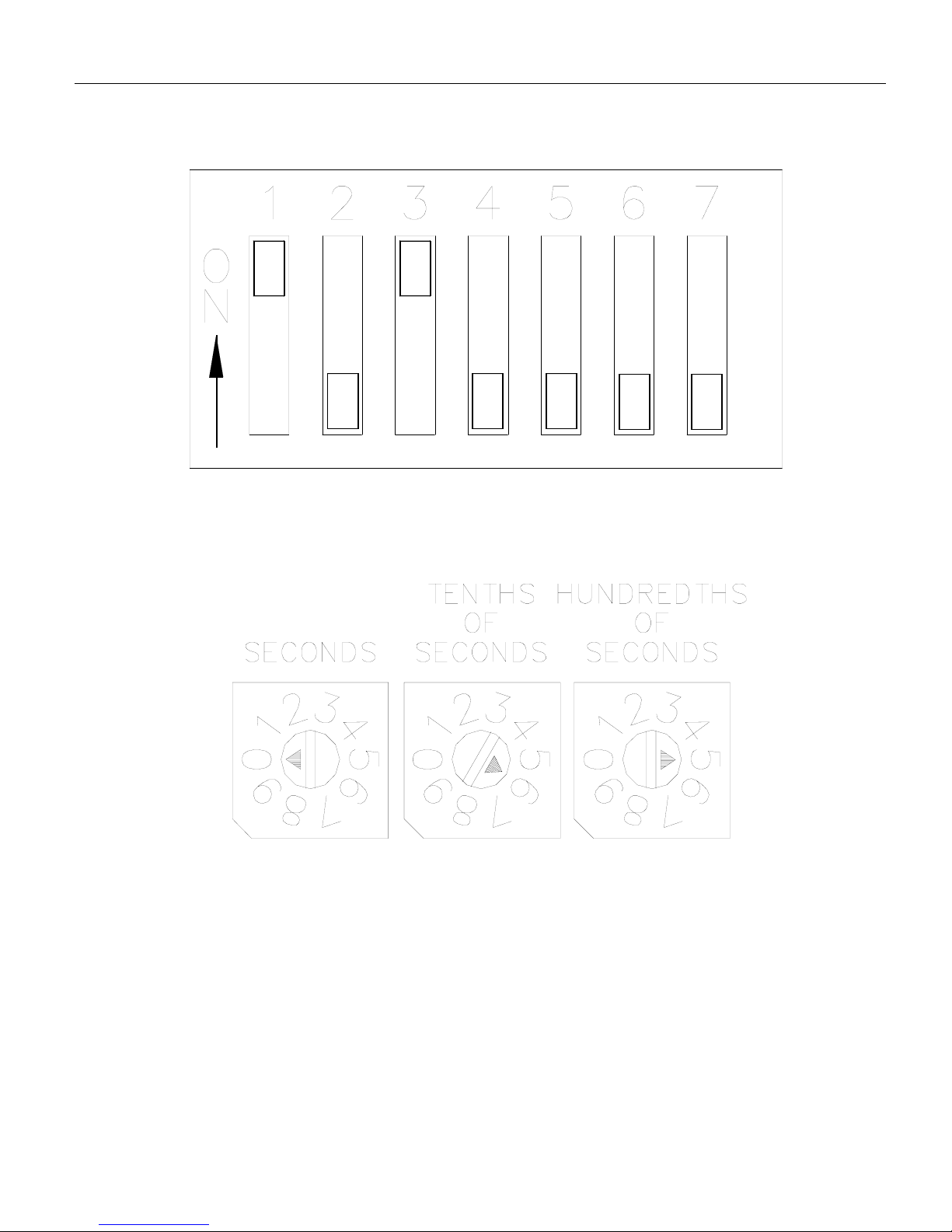
Switch settings - tachometer mode - example two
21
Application Examples
Fig. 10. Tachometer Mode-Example Two
DIP Switch Settings
Fig. 11. Tachometer Mode Example Two
Rotary DIP Switch Settings
Page 28
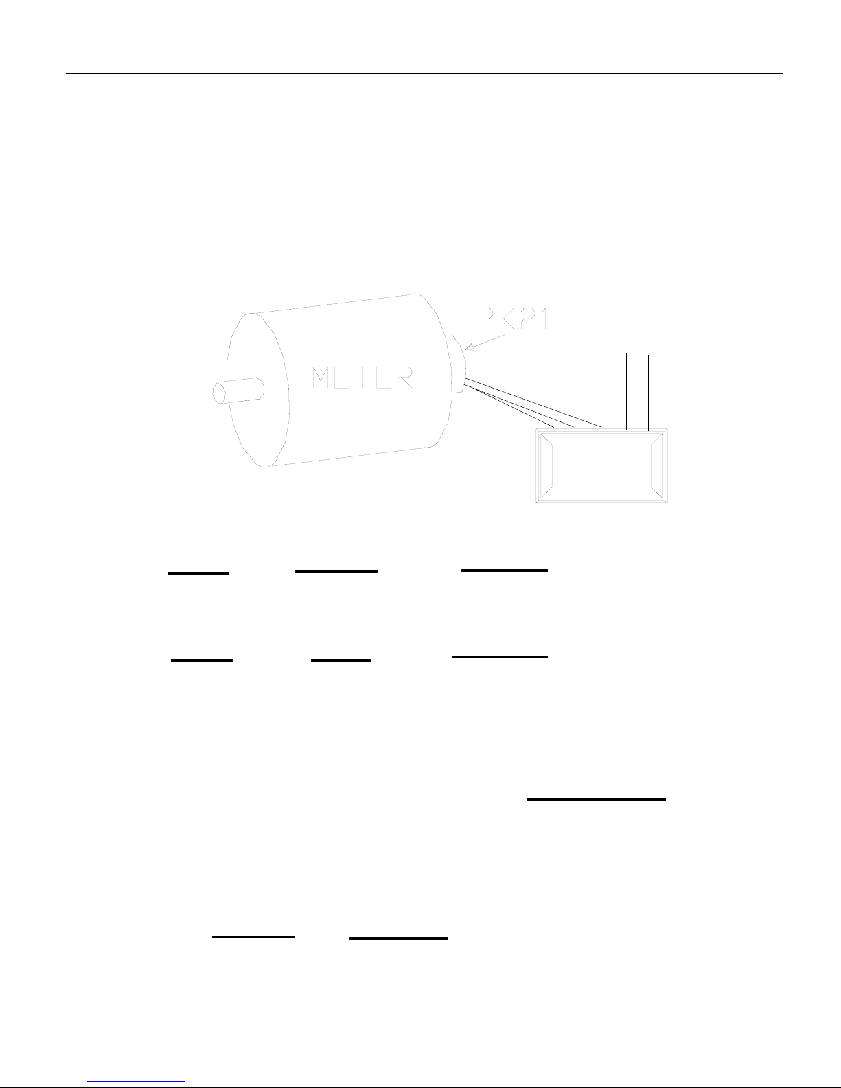
22
Mode 2 totalizer mode
Application. A VT7 is set for the totalizer mode with a
PK21-30 (30 lines per revolution) encoder. The application
speed is 500 RPM. Calculate the output frequency of the
PK21-30 and the length of time that the display will count
before rolling over.
Solution. The output frequency is
250Hz
The accumulated count is given by
count = (rate)(time) = (f)(time)
Solving this equation for time yields:
40 seconds
See page 23 for diagrams of the switch settings for this example. There is not time base for mode 2.
Application Examples
(rev.)
(min.)
f=
(pulses)
(rev.)
X
(1 min.)
(60 sec.)
X
(500)
(min.)
f=
(30)
(rev.)
X
(1 min.)
(60 sec.)
X
=
(RPM)(PPR)
60
(time)
=
(f)
(10,000)
(250)
=
=
(count)
time =
6823
L1
L2
Page 29
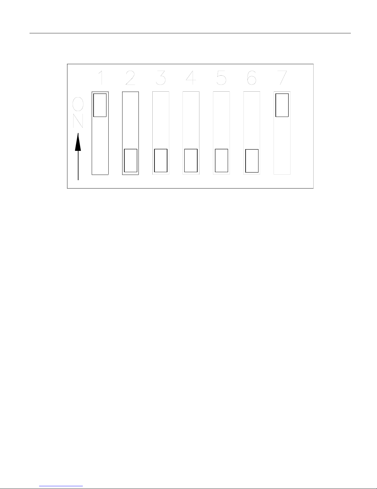
Switch settings - totalizer mode example
23
Application Examples
Fig. 12. Totalizer Mode Example DIP Switch Settings
Page 30
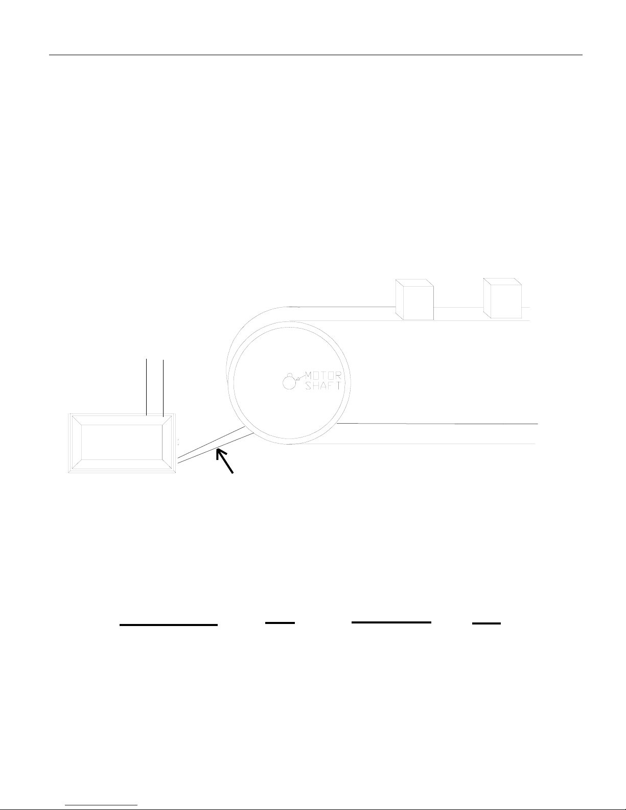
Application Examples
24
Mode 3 rate monitor mode
Application. A motor, and a variable speed drive are powering a conveyor belt carrying components. A 60 tooth magnetic
pick up, mounted to the motor shaft, sends a signal to the
VT7. It takes 50 seconds for a component to travel the length
of the belt when the motor speed is 1000 RPM. Calculate the
required time base to display the time necessary in seconds for
the components to travel the length of the belt.
Solution. It is known that time in process (DDN) is 50 seconds when the motor speed is 1000 RPM. From the equation
on page 14 we have,
5 seconds
See page 25 for diagrams of the switch settings for this example.
250,000
60
(DDN)(RPM)
t=
PPR
250,000
(50)(1000)
60
60
=
X
X
=
0050
L1
L2
Magnetic Pickup
Leads
Page 31
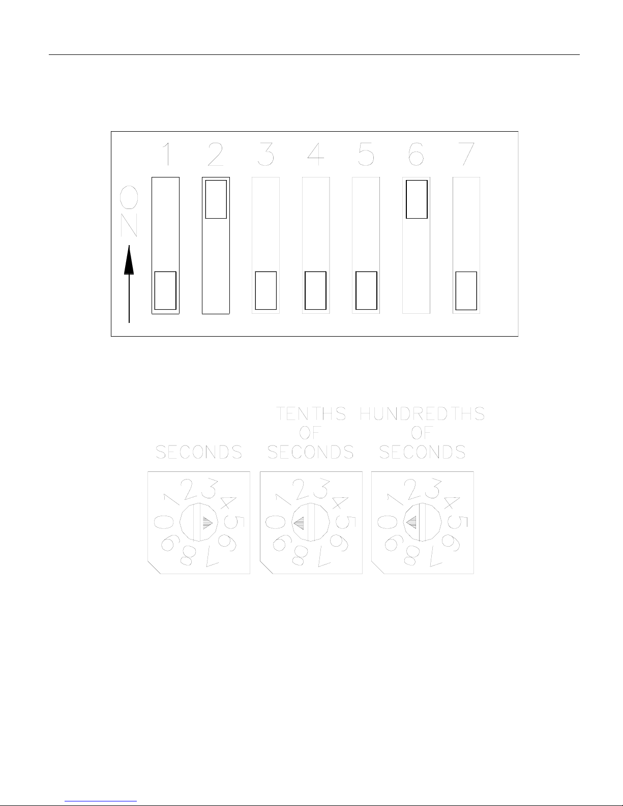
Switch settings - rate monitor mode example
25
Application Examples
Fig. 13. Mode 3 Example DIP Switch Settings
Fig. 14. Mode 3 Example Rotary
DIP Switch Settings
Page 32
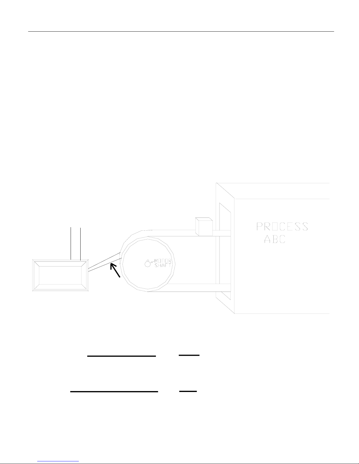
26
Application Examples
Mode 4 rate monitor mode
(min:sec or hour:min format)
Application. A motor and a variable speed drive are powering a process conveyor. A 60 tooth magnetic pickup is mounted on the back of the motor and sends a signal to the VT7.
The VT7 will display the time taken in minutes and seconds
for the process to complete. It is known that it takes 3 minutes
and 15 seconds to complete the process when the motor speed
is 1000 RPM. Calculate the required time base for this application.
Solution. Using the equation on page 14 we have
1.28 seconds
See page 27 for a diagram of the switch settings for this
example.
250,000
60
(60X+Y)(RPM)
PPR
250,000
[(60)(3)+15](1000)
60
60
=
X
X
=
3:15
L1
L2
Magnetic Pickup
Leads
t=
Page 33
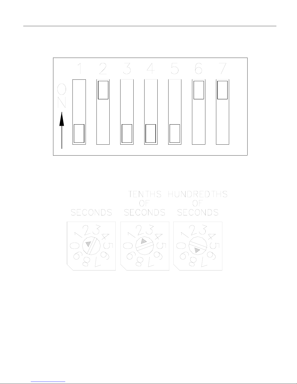
Switch settings - rate monitor mode
(min:sec or hour:min format) example
27
Application Examples
Fig. 15. Mode 4 Example DIP Switch Settings
Fig. 16. Mode 4 Example Rotary DIP Switch Settings
Page 34

Page 35

Limited Warranty
A. Warranty - Minarik Corporation (referred to as “the Corporation”) warrants that its prod-
ucts will be free from defects in workmanship and material for two (2) years from date of
shipment thereof, or 6,000 hours, whichever comes first. Within this warranty period, the
Corporation will repair or replace such products that are: (1) returned to Minarik Corporation,
901 East Thompson Avenue, Glendale, CA 91201-2011 USA; and, (2) determined by the
Corporation to be defective.
This warranty shall not apply to any product that has been subject to misuse, negligence, or
accident; or misapplied; or repaired by unauthorized persons; or improperly installed. The
Corporation is not responsible for removal, installation, or any other incidental expenses
incurred in shipping the product to and from the repair point.
B. Disclaimer - The provisions of Paragraph A are the Corporation’s sole obligation and
exclude all other warranties of merchantability for use, express or implied. The Corporation
further disclaims any responsibility whatsoever to the customer or to any other person for
injury to the person or damage or loss of property of value caused by any product that has
been subject to misuse, negligence, or accident, or misapplied or modified by unauthorized
persons or improperly installed.
C. Limitations of Liability - In the event of any claim for breech of any of the Corporation’s
obligations, whether express or implied, and particularly of any other claim or breech of warranty contained in Paragraph A, or of any other warranties, express or implied, or claim of
liability that might, despite Paragraph B, be decided against the Corporation by lawful
authority, the Corporation shall under no circumstances be liable for any consequential
damages, losses, or expense arising in connection with the use of, or inability to use, the
Corporation’s product for any purpose whatsoever.
An adjustment made under warranty does not void the warranty, nor does it imply an extension of the original two (2) year or 6,000 hour warranty period. Products serviced and/or
parts replaced on a no-charge basis during the warranty period carry the unexpired portion
of the original warranty only.
If for any reason any of the foregoing provisions shall be ineffective, the Corporation’s liability for damages arising out of its manufacture or sale of equipment, or use thereof,
whether such liability is based on warranty, contract, negligence, strict liability in tort, or otherwise, shall not in any event exceed the full purchase price of such equipment.
Any action against the Corporation based upon any liability or obligation arising hereunder
or under any law applicable to the sale of equipment or the use thereof, must be commenced within one year after the cause of such action arises.
Page 36

30
901 East Thompson Avenue
Glendale, California 91201-2011
Phone: (818) 502-1528
Fax: (818) 502-0716
www.minarikcorp.com
Document number 250–0257, Revision 1
Printed in the U.S.A – 5/98
North America $10.00, Outside North America $11.00
 Loading...