

Page 1

USER’S MANUAL
RG300 and RG400 Series
SCR, Adjustable Speed, Regenerative Drives
for DC Brush Motors
Page 2

Copyright 1998 by
Minarik Corporation
All rights reserved. No part of this manual may be reproduced or transmitted in
any form without written permission from Minarik Corporation. The information
and technical data in this manual are subject to change without notice. Minarik
Corporation and its Divisions make no warranty of any kind with respect to this
material, including, but not limited to, the implied warranties of its merchantability
and fitness for a given purpose. Minarik Corporation and its Divisions assume no
responsibility for any errors that may appear in this manual and make no
commitment to update or to keep current the information in this manual.
Printed in the United States of America.
Page 3

m Safety Warnings
• This symbol m denotes an important safety tip or warning.
Please read these sections carefully prior to performing any of
the instructions contained in that section.
• Have a qualified electrical maintenance technician install,
adjust and service this equipment. Follow the National
Electrical Code and all other applicable electrical and safety
codes, including the provisions of the Occupational Safety
and Health Act (OSHA), when installing equipment.
• Reduce the chance of an electrical fire, shock, or explosion by
proper grounding, over-current protection, thermal protection,
and enclosure. Follow sound maintenance procedures.
• It is possible for a drive to run at full speed as a result of a
component failure. Please ensure that a master switch has
been placed in the AC line to stop the drive in an emergency.
• This drive is isolated from earth ground. Circuit potentials
are at 115 VAC or 230 VAC above earth ground. Avoid direct
contact with the printed circuit board or with circuit elements
to prevent the risk of serious injury or fatality. Use a nonmetallic screwdriver for adjusting the calibration trimpots.
Page 4

ii
Contents
Specifications 1
Dimensions 3
Regenerative Drives 6
Installation 8
Mounting chassis drives . . . . . . . . . . . . . . . . . . . . . . . . . . . . . . . . . . . . . . .8
Mounting cased drives . . . . . . . . . . . . . . . . . . . . . . . . . . . . . . . . . . . . . . . .9
Cage-clamp terminal block . . . . . . . . . . . . . . . . . . . . . . . . . . . . . . . . . . . .11
Screw terminal block . . . . . . . . . . . . . . . . . . . . . . . . . . . . . . . . . . . . . . . . .12
Heat sinking . . . . . . . . . . . . . . . . . . . . . . . . . . . . . . . . . . . . . . . . . . . . . . .13
AC line and motor connection . . . . . . . . . . . . . . . . . . . . . . . . . . . . . . . . . .13
Field output . . . . . . . . . . . . . . . . . . . . . . . . . . . . . . . . . . . . . . . . . . . . . . . .15
Speed adjust potentiometer installation . . . . . . . . . . . . . . . . . . . . . . . . . . .16
Speed adjust potentiometer connections . . . . . . . . . . . . . . . . . . . . . . . . . .17
Line fusing for RG300/400 Series . . . . . . . . . . . . . . . . . . . . . . . . . . . . . . .18
Voltage follower . . . . . . . . . . . . . . . . . . . . . . . . . . . . . . . . . . . . . . . . . . . .19
Operation 20
Before applying power . . . . . . . . . . . . . . . . . . . . . . . . . . . . . . . . . . . . . . .20
Startup . . . . . . . . . . . . . . . . . . . . . . . . . . . . . . . . . . . . . . . . . . . . . . . . . . .20
Chassis drives . . . . . . . . . . . . . . . . . . . . . . . . . . . . . . . . . . . . . . . . .20
Cased drives . . . . . . . . . . . . . . . . . . . . . . . . . . . . . . . . . . . . . . . . . .21
Line starting and line stopping . . . . . . . . . . . . . . . . . . . . . . . . . . . . . . . . . .22
Automatic restart upon power restoration . . . . . . . . . . . . . . . . . . . . . . . . .21
Regenerative deceleration . . . . . . . . . . . . . . . . . . . . . . . . . . . . . . . . . . . .21
Regenerative brake . . . . . . . . . . . . . . . . . . . . . . . . . . . . . . . . . . . . . . . . . .23
Decelerate to minimum speed . . . . . . . . . . . . . . . . . . . . . . . . . . . . . . . . . .24
Page 5

iii
Contents
Warning . . . . . . . . . . . . . . . . . . . . . . . . . . . . . . . . . . . . . . . . . . . . . . . . . .25
Calibration 26
MIN SPD . . . . . . . . . . . . . . . . . . . . . . . . . . . . . . . . . . . . . . . . . . . . . . . . .26
MAX SPD . . . . . . . . . . . . . . . . . . . . . . . . . . . . . . . . . . . . . . . . . . . . . . . . .26
FWD TQ . . . . . . . . . . . . . . . . . . . . . . . . . . . . . . . . . . . . . . . . . . . . . . . . . .27
REV TQ . . . . . . . . . . . . . . . . . . . . . . . . . . . . . . . . . . . . . . . . . . . . . . . . . .28
IR COMP . . . . . . . . . . . . . . . . . . . . . . . . . . . . . . . . . . . . . . . . . . . . . . . . .29
FWD ACC . . . . . . . . . . . . . . . . . . . . . . . . . . . . . . . . . . . . . . . . . . . . . . . .31
REV ACC . . . . . . . . . . . . . . . . . . . . . . . . . . . . . . . . . . . . . . . . . . . . . . . . .31
DB . . . . . . . . . . . . . . . . . . . . . . . . . . . . . . . . . . . . . . . . . . . . . . . . . . . . . .32
Application Notes 33
Connection to other Minarik devices . . . . . . . . . . . . . . . . . . . . . . . . . . . . .33
Optional speed adjust potentiometer connections . . . . . . . . . . . . . . . . . . .35
Troubleshooting 38
Block Diagram 43
Factory Prewired Connections (for Cased Drives) 44
CE Compliance 46
Line filters . . . . . . . . . . . . . . . . . . . . . . . . . . . . . . . . . . . . . . . . . . . . . . . . .47
Armature filters . . . . . . . . . . . . . . . . . . . . . . . . . . . . . . . . . . . . . . . . . . . . .48
Replacement Parts 50
Limited Warranty inside back cover
Page 6

iv
Illustrations
Fig. Description Page
1. RG300UA, RG310UA and RG400UA Dimensions . . . . . . . . . . . . . . . . . . . .3
2. RG300UA-S, RG310UA-S and RG400UA-S Dimensions . . . . . . . . . . . . . . .4
3. Cased Drive Dimensions . . . . . . . . . . . . . . . . . . . . . . . . . . . . . . . . . . . . . . .5
4. Four-Quadrant Operation . . . . . . . . . . . . . . . . . . . . . . . . . . . . . . . . . . . . . .7
5. Cage-Clamp Terminal Block . . . . . . . . . . . . . . . . . . . . . . . . . . . . . . . . . . .11
6. Screw Terminal Block . . . . . . . . . . . . . . . . . . . . . . . . . . . . . . . . . . . . . . . .12
7. Chassis Drive Connections . . . . . . . . . . . . . . . . . . . . . . . . . . . . . . . . . . . .13
8. Cased Drive Connections . . . . . . . . . . . . . . . . . . . . . . . . . . . . . . . . . . . . .14
9. Speed Adjust Potentiometer Installation . . . . . . . . . . . . . . . . . . . . . . . . . .16
10. Speed Adjust Potentiometer Connections . . . . . . . . . . . . . . . . . . . . . . . . .17
11. Voltage follower . . . . . . . . . . . . . . . . . . . . . . . . . . . . . . . . . . . . . . . . . . . .19
12. Regenerative Deceleration Switch connection . . . . . . . . . . . . . . . . . . . . . .22
13. Run/Decelerate to Minimum Speed Switch . . . . . . . . . . . . . . . . . . . . . . . .24
14. Typical FWD TQ, REV TQ and IR COMP Settings . . . . . . . . . . . . . . . . . . .30
15. Deadband Settings . . . . . . . . . . . . . . . . . . . . . . . . . . . . . . . . . . . . . . . . . .32
16. Connection to Other Minarik Devices . . . . . . . . . . . . . . . . . . . . . . . . . . . .33
17. RG300/400 Connection to 200-0386A Logic Board . . . . . . . . . . . . . . . . . .34
18. FWD-REV Switch . . . . . . . . . . . . . . . . . . . . . . . . . . . . . . . . . . . . . . . . . . .35
19. FWD-STOP-REV Switch . . . . . . . . . . . . . . . . . . . . . . . . . . . . . . . . . . . . . .35
20. Independent Adjustable Speeds . . . . . . . . . . . . . . . . . . . . . . . . . . . . . . . .36
21. Independent Forward and Reverse Speeds . . . . . . . . . . . . . . . . . . . . . . . .36
22. Independent Forward and Reverse Speed with FWD-STOP-REV Switch . .37
23. RG300/400 Series Block Diagram . . . . . . . . . . . . . . . . . . . . . . . . . . . . . . .43
24. Prewired Power Input Connections . . . . . . . . . . . . . . . . . . . . . . . . . . . . . .44
25. Prewired Speed Adjust Potentiometer Connections . . . . . . . . . . . . . . . . . .45
Page 7

v
Tables
Table Description Page
1. Field Output Connections . . . . . . . . . . . . . . . . . . . . . . . . . . . . . . . . . . .15
2. Line Fusing for RG Series Drives . . . . . . . . . . . . . . . . . . . . . . . . . . . . .18
3. Corcom® Filters for CE Compliance . . . . . . . . . . . . . . . . . . . . . . . . . . .47
4. Minarik® Filters for CE Compliance . . . . . . . . . . . . . . . . . . . . . . . . . . .48
5. Replacement Parts . . . . . . . . . . . . . . . . . . . . . . . . . . . . . . . . . . . . . . . .50
Page 8

Page 9

Specifications
Maximum
Armature Armature Horsepower
Model Current Voltage Range
RG310 3.0 ADC 0 – 90 VDC 1/20 – 1/8
RG300 10.0 ADC † 0 – 90 VDC 1/4 – 1 †
RG400 10.0 ADC † 0 – 180 VDC 1/2 – 2 †
† Maximum armature current and horsepower range apply when drive is attached to
additional heat sink: Minarik part number 223-0235. Use heat sink when armature
current is above 5 ADC. Heat sinks are pre-mounted on RG300 and RG400 series
cased drives.
AC Line Voltage
RG300/RG310 115 VAC, ±10%, 50/60 Hz, single phase
RG400 230 VAC, ±10%, 50/60 Hz, single phase
Form Factor 1.37 at base speed
Field Voltage
115 VAC Input 50 VDC (F1 to L1); 100 VDC (F1 to F2)
230 VAC Input 100 VDC (F1 to L1); 200 VDC (F1 to F2)
Maximum Field Current 1 ADC
Acceleration Time Range 0.5 – 6 seconds
Deceleration Time Range 0.5 – 6 seconds
Analog Input Voltage Range (isolated; RB1 to S2) –10 VDC to +10 VDC
Input Impedance (RB1 to S2) 32KΩ
Load Regulation 1% of base speed or better
Vibration 0.5G max. (0 – 50 Hz)
0.1G max. (>50Hz)
Ambient Temperature Range (chassis drive) 10°C – 55°C
Ambient Temperature Range (cased drive) 10°C – 40°C
Safety Certification UL file # E132235
CSA file # LR41380
CE Certificate of Compliance
1
Page 10

2
Specifications
Drive option description - by suffix
Terminal
Suffix Style Block Type
A NEMA 4 Cage-Clamp*
A–S NEMA 4 Screw
UA Chassis Cage-Clamp*
UA–S Chassis Screw
*Note: All cased regenerative drives in this series have a two slot
screw terminal block for connecting the AC line voltage
(see page 18).
Page 11
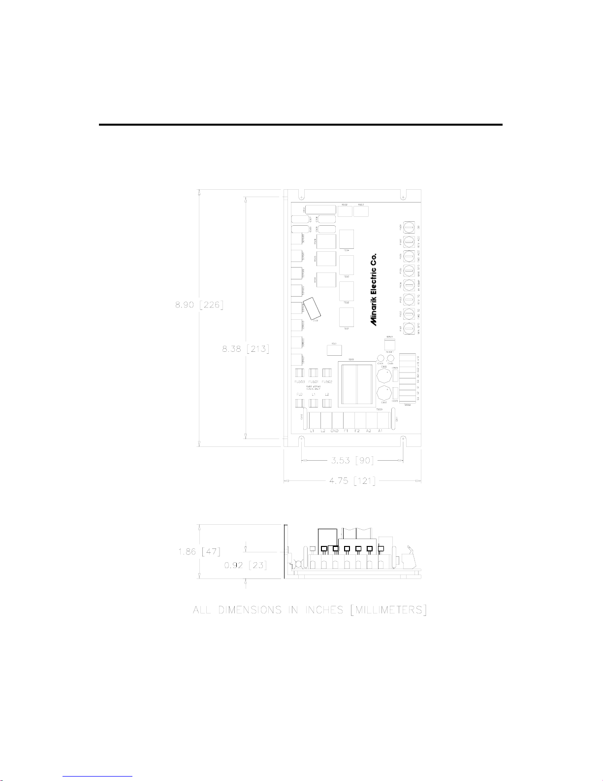
3
Dimensions
Figure 1. RG300UA, RG310UA, and RG400UA Dimensions
Page 12
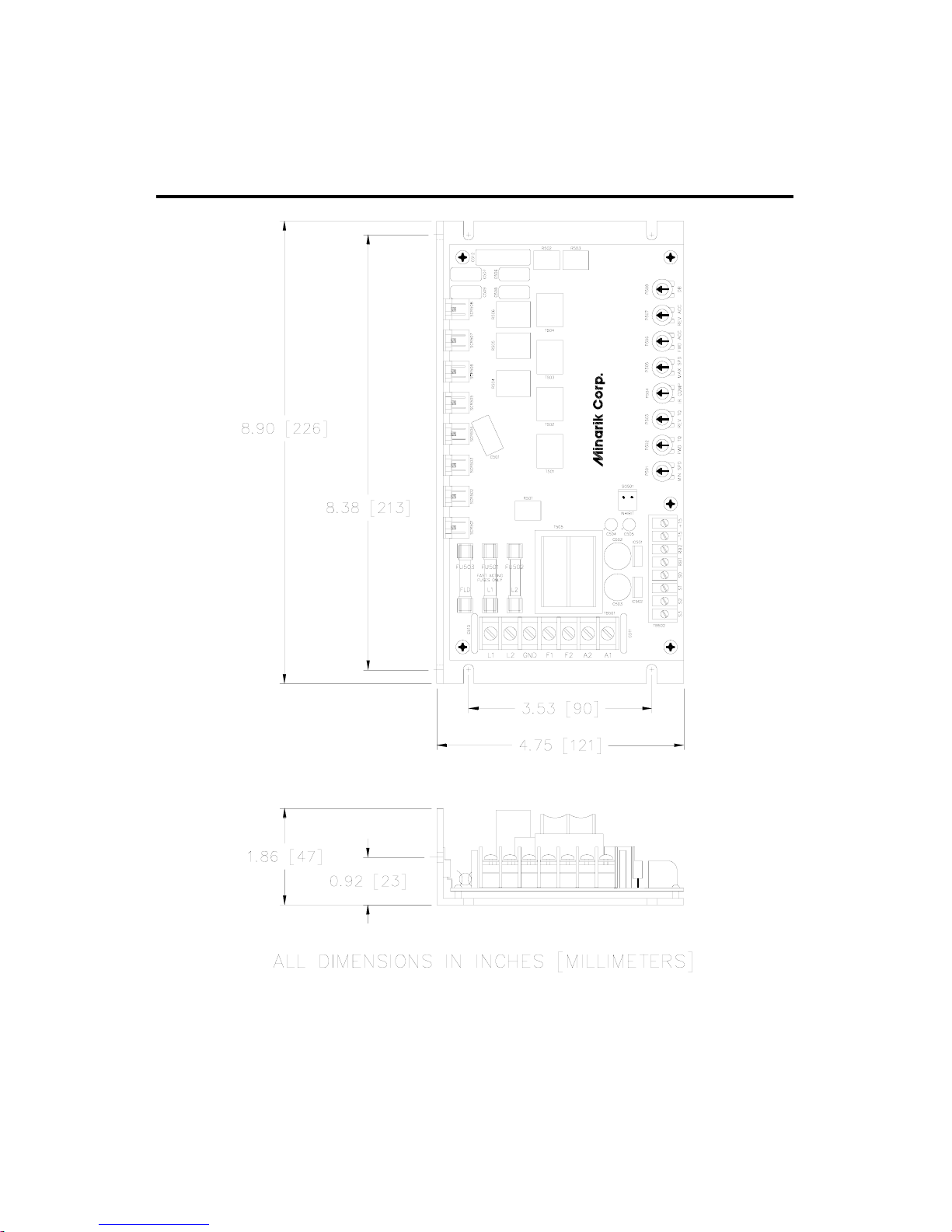
4
Dimensions
Figure 2. RG310UA–S, RG300UA–S, RG400UA–S,
Dimensions
Page 13
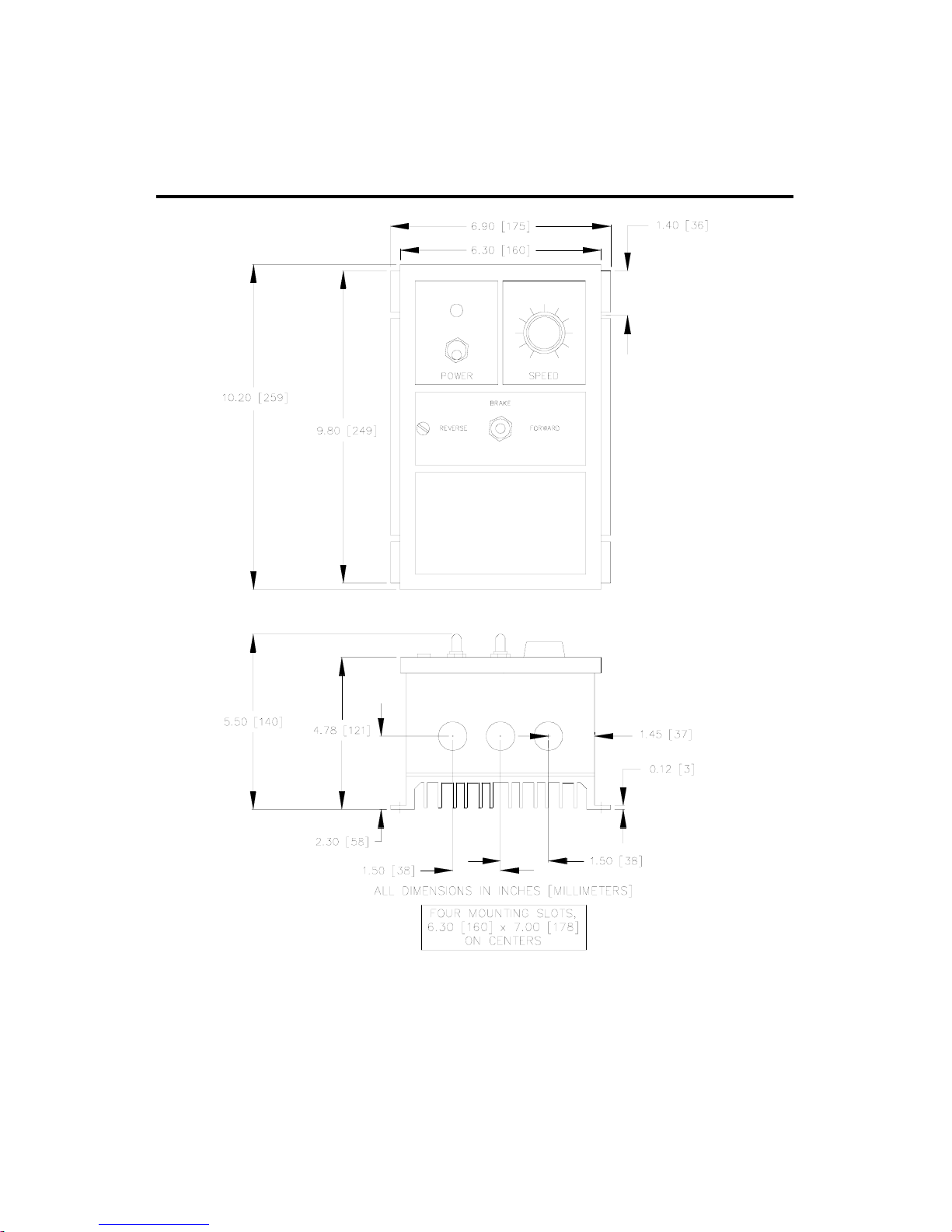
5
Dimensions
Figure 3. RG310A, RG300A, RG400A
and RG310A–S, RG300A–S, RG400A–S
Cased Drive Dimensions
Page 14

6
Regenerative Drives
Most non-regenerative, variable speed, DC drives control
current flow to a motor in one direction. The direction of
current flow is the same direction as the motor rotation.
Non-regenerative drives operate in Quadrant 1, and also in
Quadrant 3 if the drive is reversible (see Figure 4). Motors
must stop before reversing direction. Unless dynamic braking
is used, non-regenerative drives cannot oppose an overhauling
load, and cannot decelerate a load faster than coasting to a
lower speed.
Regenerative drives operate in two additional quadrants:
Quadrant 2 and Quadrant 4. In these quadrants, motor torque
is in the opposite direction of motor rotation.
Regenerative drives can reverse a motor without contactors,
switches, brake resistors, and inhibit plugs. They can also
control an overhauling load and decelerate a load faster than it
would take to coast to a lower speed.
Page 15
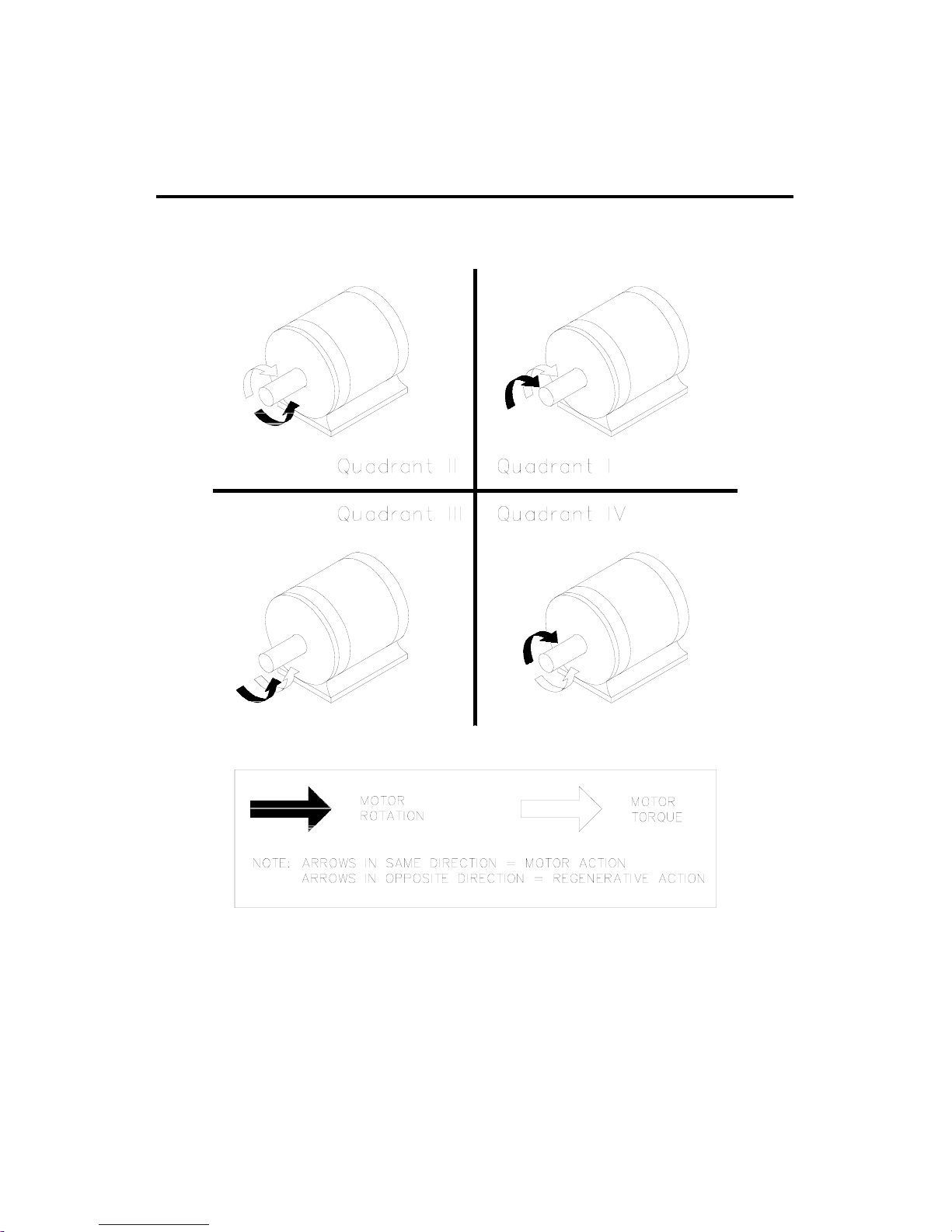
7
Regenerative Drives
Figure 4. Four Quadrant Operation
Page 16

Installation
ASSUMPTIONS: Minarik drives supply motor voltage from
A1 and A2 terminals. It is assumed throughout this manual
that, when A1 is positive with respect to A2, the motor will
rotate clockwise (CW) while looking at the output shaft
protruding from the front of the motor. If this is opposite of
the desired rotation, simply reverse the wiring of A1 and A2
with each other.
Mounting chassis drives
Drive components are sensitive to electrostatic fields. Avoid
contact with the circuit board directly. Hold the drive by the
chassis only.
Protect the drive from dirt, moisture, and accidental contact.
Provide sufficient room for access to the terminal block and
calibration trimpots.
Mount the drive away from other heat sources. Operate
the drive within the specified ambient operating temperature
range.
Prevent loose connections by avoiding excessive vibration
of the drive.
8
Page 17

Mounting cased drives
NEMA 4X cased drives come with three 0.88 inch (22 mm)
conduit knockout holes at the bottom of the case. The units
may be vertically wall mounted using the four 0.188 inch
(5 mm) slotted holes on the attached heat sink. The cased
drives in this series may be bench mounted. For motor loads
greater than 8 ADC the heat sink fins must be in the vertical
direction. Detailed step by step instructions begin on the
page 14.
9
Installation
Mount the drive with its board in either a horizontal or
vertical plane. Six 0.188 inch (4.8 mm) wide slots in the
chassis accept #8 pan head screws. Fasten either the large
base or the narrow flange of the chassis to the subplate.
The chassis must be earth grounded for noise suppression. To
ground the chassis, connect earth ground to the GND terminal
on terminal block 501 (TB501).
Page 18

Mounting cased drives (continued)
1. Install the mounting screws.
2. For access to the terminal strip, turn the slotted screw on
the front cover counterclockwise until it is free from the
case. The right side of the cover is hinged to the case. Lift
or pull the slotted screw to open the case.
3. Carefully remove the conduit knockouts by tapping them
into the case and twisting them off with pliers.
4. Install conduit hardware through the 0.88 inch (22 mm)
conduit holes. Connect external wiring to the terminal
block.
5. Grasp the slotted screw and tilt the front cover back into
place. Avoid pinching any wires between the front cover
and the case.
6. Turn the slotted screw clockwise until tight to secure the
front cover.
7. Set the POWER switch OFF position before applying the
AC line voltage.
10
Installation
Page 19
11
Installation
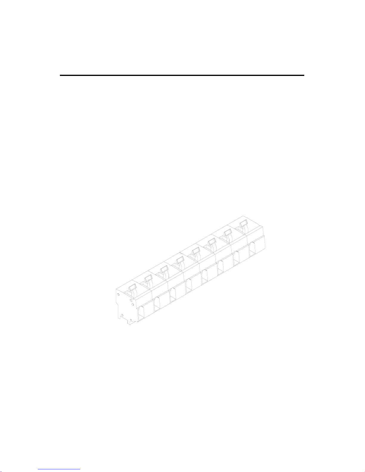
Figure 5. Cage-Clamp Terminal Block
Cage-clamp terminal block
Most connections to RG300 and RG400 Series drives (UA
and A versions) are made to a cage-clamp terminal block
(Figure 5). To insert a wire into the terminal block, press
down on the lever arm using a small screwdriver. Insert
stripped wire into the large opening in front of the terminal
block. Release the lever arm to clamp the wire.
Note: All AC line voltage connections to cased regen drives
are made to screw terminals.
Page 20
12
Installation
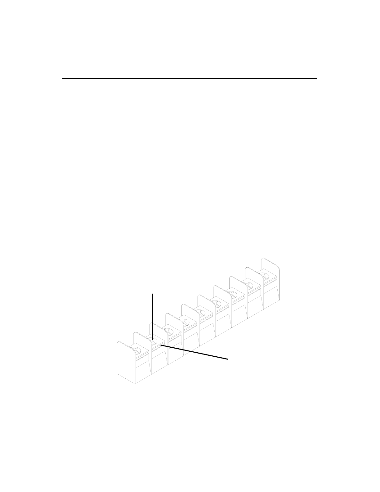
Screw terminal block
Connections to RG300 and RG400 Series drives (A-S version
and UA-S) are made to screw terminal blocks. The larger one
is shown in Figure 6.
Using a screwdriver, turn the terminal block screw counterclockwise to open the wire clamp. Insert stripped wire into the
wire clamp. Turn the terminal block screw clockwise to clamp
the wire.
Terminal Block Screw
Wire Clamp
Figure 6. Screw Terminal Block
Page 21
13
Installation
Heat sinking
Chassis RG models require an additional heat sink
when the continuous armature current is above 5 ADC. Use
Minarik
®
part number 223-0235. All cased drives have
sufficient heat sinking in their basic configurations. Use a
thermally conductive heat sink compound (such as Dow
Corning
®
340 Heat Sink compound) between the drive chassis
and the heat sink surface for optimum heat transfer.
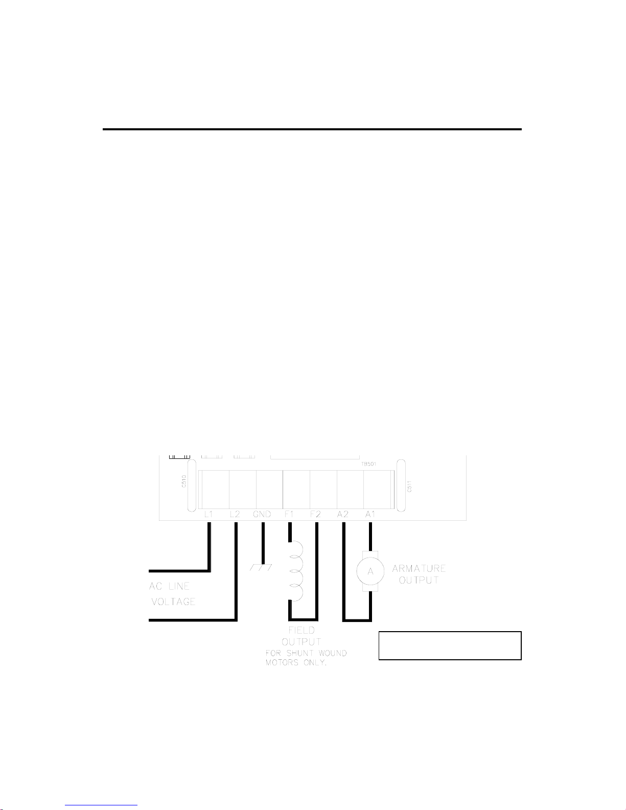
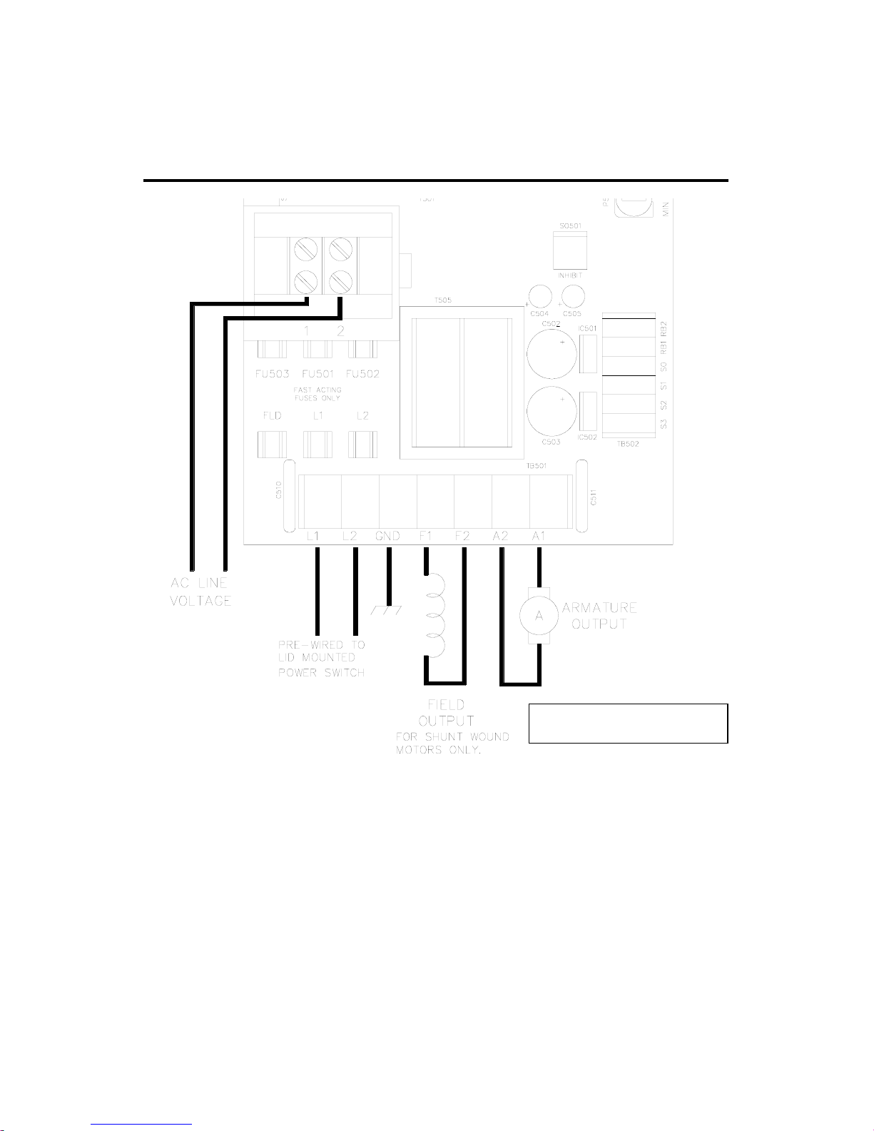
AC line and motor connections
Use 12 AWG or 14AWG standard wire for connecting the
line and the armature. Strip the wire insulation 0.25 inches
(6 mm). See Figures 7 and 8 for AC line and motor
connections to chassis and cased drives.
Figure 7. Chassis Drive Connections
Field Output Connections
see page 19
Page 22
14
Installation
Figure 8. Cased Drive Connections
Field Output Connections
see page 19
Page 23

15
Installation
Field output
The field output is for shunt wound motors only. Do not
make any connections to F1 and F2 when using a
permanent magnet motor.
Use 18 AWG wire to connect the field output to a shunt
wound motor. Table 1 lists the field output connections.
Table 1. Field Output Connections
Line Voltage Approximate Connect Motor
(VAC) Field Voltage (VDC) Field To
115 50 F1 and L1
115 100 F1 and F2
230 100 F1 and L1
230 200 F1 and F2
Page 24
16
Installation
Speed adjust potentiometer installation
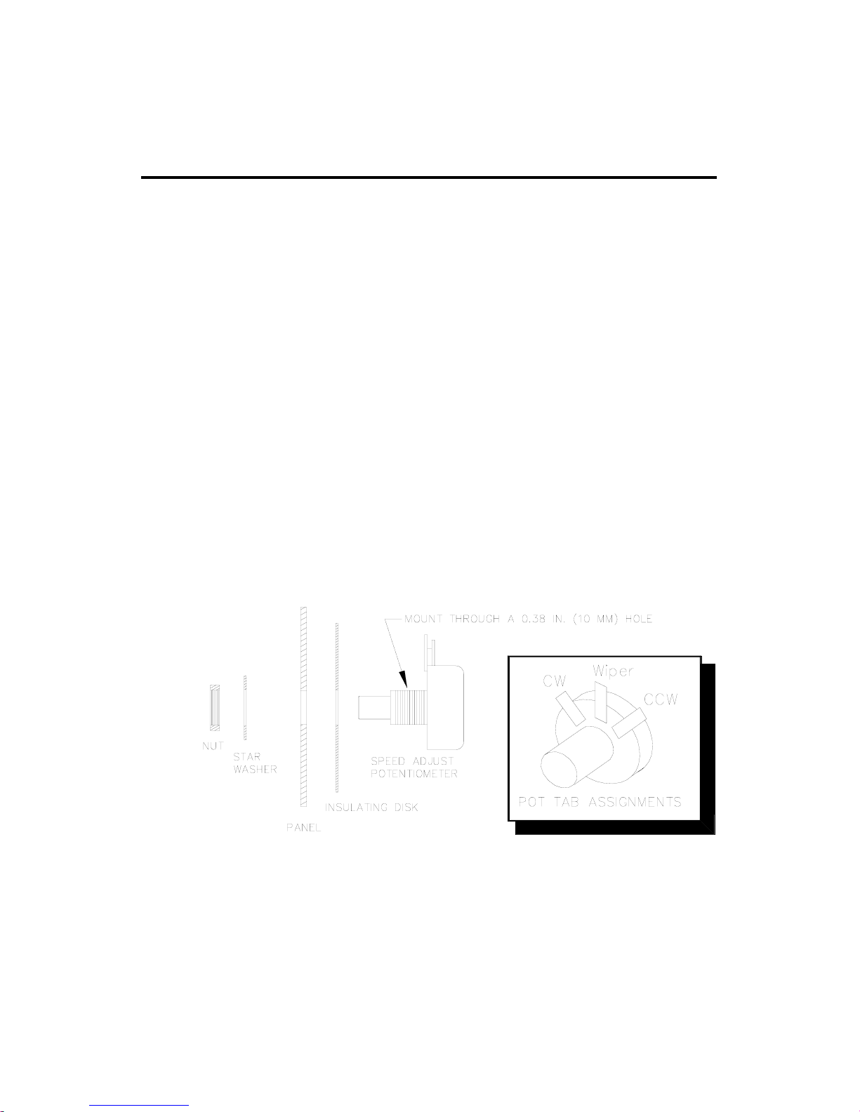
Speed adjust potentiometers are pre-installed on all cased
drives. On chassis drives, install the circular insulating disk
between the panel and the 10KΩ speed adjust potentiometer.
Mount the speed adjust potentiometer through a 0.38 in.
(0.96 cm) hole with the hardware provided (see Figure 9).
Twist the speed adjust potentiometer wire to avoid picking up
unwanted electrical noise. If potentiometer leads are longer
than 18 in. (46 cm), use shielded cable.
m Warning Be sure that the potentiometer tabs do not make
contact with the potentiometer enclosure. Grounding the input
will cause damage to the drive.
Figure 9. Speed Adjust Potentiometer
Page 25
17
Installation
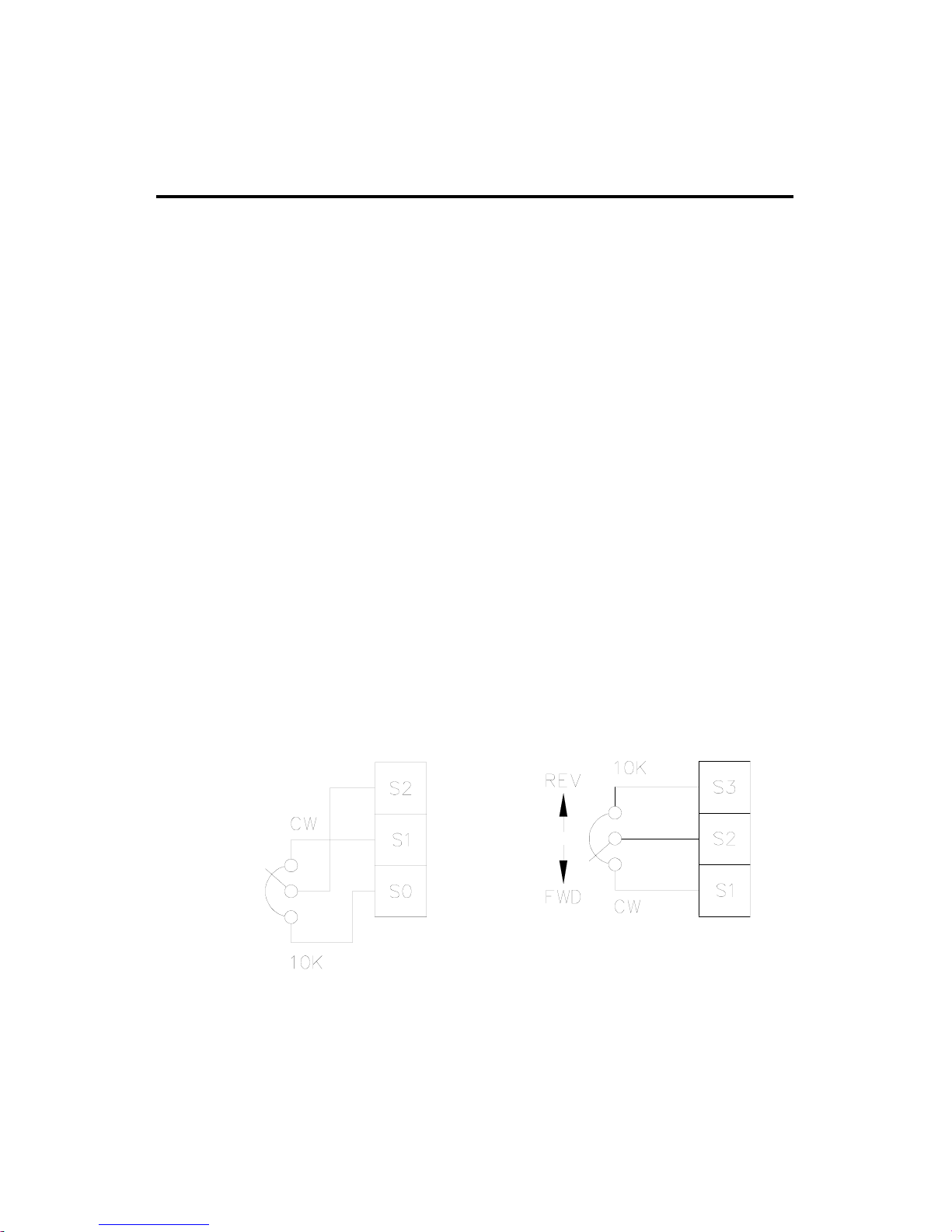
Figure 10. Speed Adjust Potentiometer Connections for (a)
Unidirectional Operation, and (b) Bidirectional Operation
(a)
(b)
Speed adjust potentiometer connections
The motor can operate in one direction (unidirectional) or in
two directions (bidirectional) depending on how the speed
adjust potentiometer is connected to the drive.
Connect the speed adjust potentiometer as shown in Figure
10(a) for speed control in one direction.
Connect the speed adjust potentiometer as shown in Figure
10(b) for speed control in two directions. The motor does not
rotate when the wiper is in the center position. Turning the
wiper CW from the center position causes the motor to rotate
in one direction, while turning the wiper CCW from the center
position causes the motor to rotate in the opposite direction.
Refer to the Application Notes section for additional speed
adjust potentiometer connections.
Page 26

18
Installation
Line fuses
Minarik drives require fuses for protection. Use fast acting
fuses rated for 250 VAC or higher, and approximately 150%
of the maximum armature current. Fuse only L1 when the line
voltage is 115 VAC. Fuse both L1 and L2 when the line
voltage is 230 VAC.
Table 2 lists the recommended line fuse sizes.
Table 2. Recommended Line Fuse Sizes
90 VDC Motor 180 VDC Max. DC Armature AC Line Fuse
Horsepower Horsepower Current (amps) Size (amps)
1/20 1/10 0.5 3
1/15 1/8 0.8 3
1/8 1/4 1.5 5
1/6 1/3 1.7 5
1/4 1/2 2.6 8
1/3 3/4 3.5 8
1/2 1 5.0 10
3/4 1 1/2 7.6 15
1 2 10 20
Minarik Corporation offers two fuse kits: part number
050–0069 (3–8A Fuse Kit) and 050–0073 (5–20A Fuse Kit).
Both fuse kits include a 1/2A pico fuse (part number
050–0064) which protects the transformer and logic.
Page 27
Voltage follower
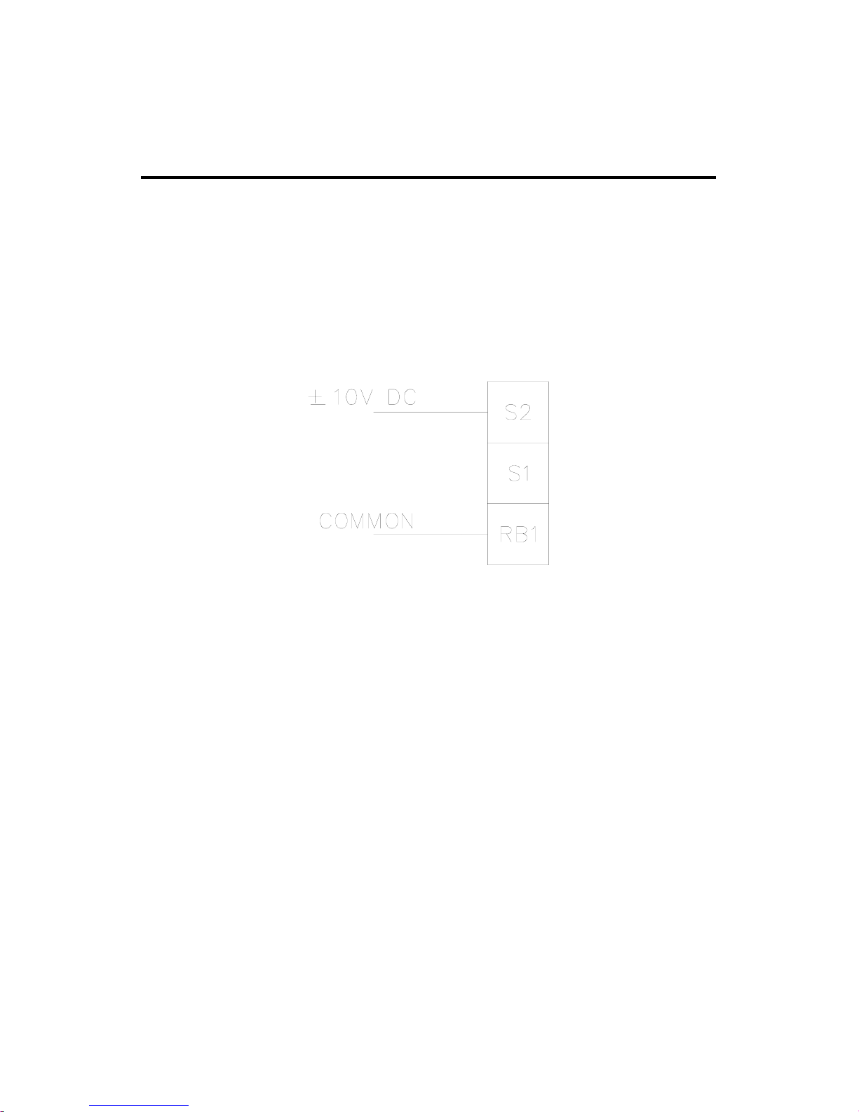
The drive may be wired to follow a floating (isolated)
0 to ±10 VDC signal that is isolated from earth ground instead
of using a speed adjust potentiometer. Connect the signal input
to S2, and the signal common to RB1 (see Figure 11).
19
Installation
Figure 11. Voltage Follower Connection
Page 28

20
Operation
Before applying power
1. Check connections before applying AC line voltage to
the drive.
2. Check that no conductive material is present on the printed
circuit board.
Startup
Chassis drives
1. Set the speed adjust potentiometer for zero speed.
2. Apply AC line voltage.
3. Slowly advance the speed adjust potentiometer clockwise
(CW). The motor slowly accelerates as the potentiometer is
turned CW. Continue until the desired speed is reached.
4. Remove AC line voltage from the drive to coast the motor
to a stop.
Page 29

21
Operation
Cased drives
1. Set the FORWARD/BRAKE/REVERSE switch to the
BRAKE position.
2. Set the speed adjust potentiometer to “0” (full CCW).
3. Apply AC line voltage.
4. Set the POWER switch to the ON position.
5. Set the FORWARD/BRAKE/REVERSE switch to the
desired direction of rotation.
7. Slowly advance the speed adjust potentiometer clockwise
(CW). The motor slowly accelerates as the potentiometer is
turned CW. Continue until the desired speed is reached.
8. To brake the motor, set the FORWARD/BRAKE/REVERSE
switch to the BRAKE position. To coast the motor to a stop,
set the POWER switch to the OFF position.
9. To reverse direction:
a. Set the FORWARD/BRAKE/REVERSE switch to the
BRAKE position.
b. After the motor comes to a complete stop, set the
FORWARD/BRAKE/REVERSE switch to the desired
direction of rotation.
10. Set the POWER switch to OFF to remove power from the
drive.
Page 30
22
Operation
Line starting and line stopping
Line starting and line stopping (applying and removing
AC line voltage) is recommended for infrequent starting and
stopping of a drive only. When AC line voltage is applied to
the drive, the motor accelerates to the speed set by the speed
adjust potentiometer. When AC line voltage is removed, the
motor coasts to a stop.
Automatic restart upon power restoration
All drives automatically run to set speed when power is
applied. Wiring a latching relay into the AC line is one way
to prevent automatic restarting following a power outage.
Regenerative deceleration
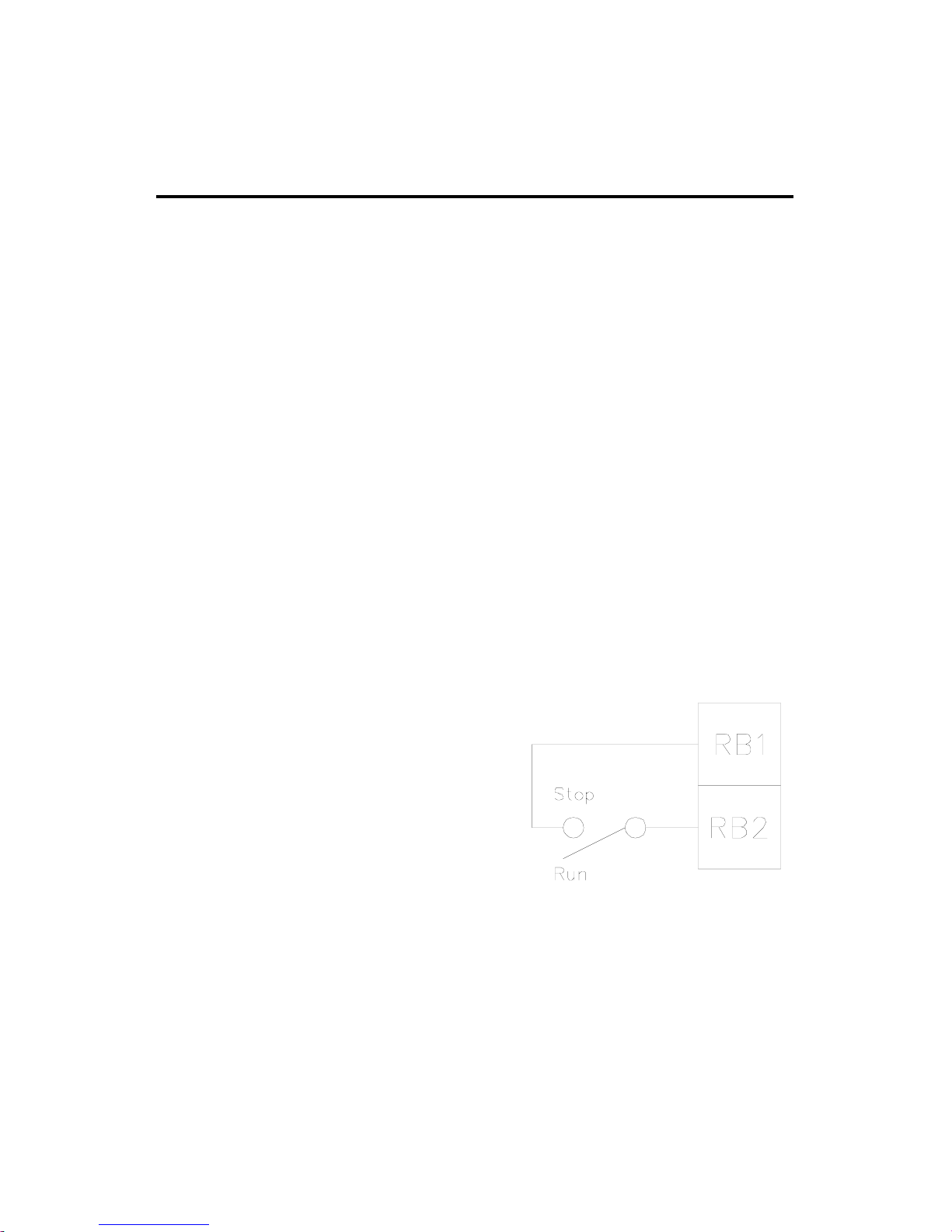
Short terminals RB1 and RB2 to
regeneratively decelerate a motor
to a stop (Figure 12). Since
terminal RB1 bypasses the MIN
SPD circuit, shorting RB1 and
RB2 will decelerate a motor to a
stop instead of minimum speed.
Calibrate the deceleration time
by adjusting the oppositedirection acceleration trimpot.
Figure 12. Regenerative
Deceleration Switch
Connection
Page 31

23
Operation
Regenerative brake
Short the INHIBIT terminals to regeneratively brake the
motor. Reopening the INHIBIT terminals causes the motor to
accelerate to set speed.
The INHIBIT terminals bypass both the MIN SPD circuit
and the deceleration circuit. This causes the motor to stop
rapidly when the INHIBIT terminals are shorted. Braking
torque is determined by the opposite-direction torque setting.
Minarik Corporation offers two accessory plug harnesses for
the INHIBIT terminals:
Minarik
®
Part Number Description
201–0024 Inhibit plug with 18 in. (46 cm) wires
201–0079 Inhibit plug with 36 in. (91 cm) wires
Always twist inhibit wires and separate them from other
power-carrying wires or sources of electrical noise. Use
shielded cable if the inhibit wires are longer than 18 inches
(46 cm). If shielded cable is used, ground only one end of the
shield to earth ground. Do not ground both ends of the
shield.
Page 32
24
Operation
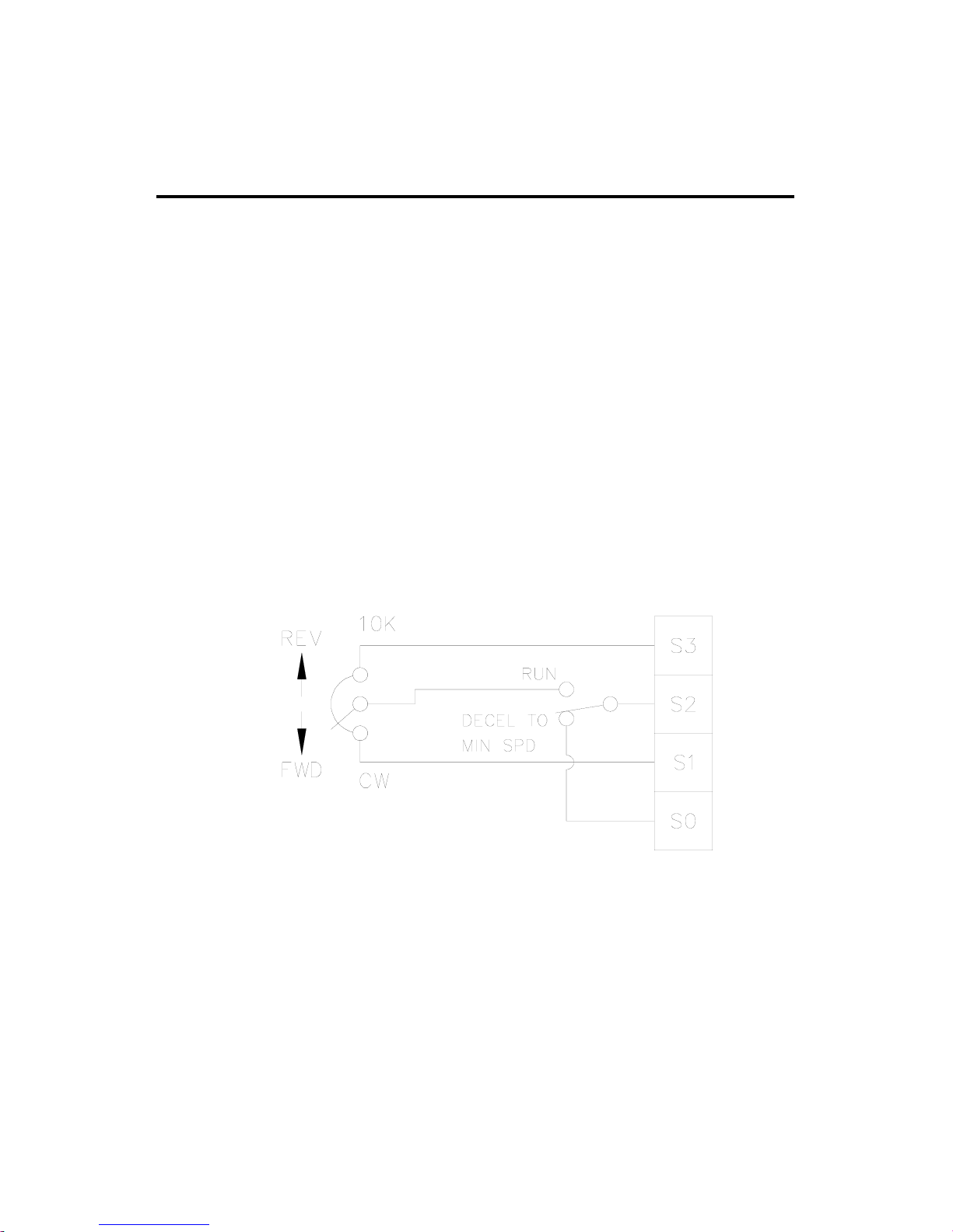
Figure 13. Run/Decelerate to Minimum Speed Switch
(shown with bidirectional speed adjust
potentiometer connection)
Decelerate to minimum speed
The circuit shown in Figure 13 may be used to decelerate a
motor to a minimum speed. Closing the switch between S2
and S0 decelerates the motor from set speed to a minimum
speed determined by the MIN SPD trimpot setting. If the MIN
SPD trimpot is set full CCW, the motor decelerates to zero
speed when the switch between S2 and S0 is closed. The
applied direction ACCEL trimpot (FWD or REV) setting
determines the rate at which the drive decelerates. Set the
switch to the RUN position to accelerate the motor to set
speed at a rate determined by the applied direction ACCEL
trimpot setting.
Page 33

25
Operation
m Warning
For frequent starts and stops, use regenerative deceleration
(shorting RB1 and RB2), regenerative braking (shorting
INHIBIT terminals to each other), or decelerating to
minimum speed (shorting S2 to S0). Do not use any of these
methods for emergency stopping. They may not stop a drive
that is malfunctioning. Removing AC line power (both L1
and L2) is the only acceptable method for emergency
stopping.
INHIBIT is part of the speed reference circuit. When engaged,
other functions, such as IR COMP, FWD TQ and REV TQ
may still be active.
Frequent regenerative deceleration, regenerative braking,
coasting to a stop, or decelerating to minimum speed produces
high torque. This may cause damage to motors, especially
gearmotors that are not properly sized for the application.
When sizing gearmotors with regenerative drives, check the
gearbox torque rating is not exceeded.
Page 34

Calibration
Each drive is factory calibrated to its maximum horsepower
rating. Readjust the calibration trimpot settings to
accommodate lower horsepower motors.
All adjustments increase with CW rotation, and decrease with
CCW rotation. Use a non-metallic screwdriver for calibration.
Each trimpot is identified on the printed circuit board.
MIN SPD
The MIN SPD setting determines the minimum speed when
the speed adjust potentiometer is turned full CCW. It is factory
set to zero speed. The minimum speed feature applies only
when the drive is operating in unidirectional mode.
To calibrate MIN SPD:
1. Set the speed adjust potentiometer full CCW.
2. Adjust the MIN SPD trimpot until the motor turns at the
desired minimum speed.
MAX SPD
The MAX SPD setting determines the maximum motor speed
when the speed adjust potentiometer is turned full CW. It is
factory set for maximum rated motor speed.
26
Page 35

To calibrate MAX SPD:
1. Set the MAX trimpot full CCW.
2. Turn the speed adjust potentiometer full CW.
3. Adjust the MAX SPD trimpot until the desired maximum
motor speed is reached.
FWD TQ
The FWD TQ setting determines the maximum torque for
accelerating and driving the motor in the forward direction. It
also sets the maximum torque for decelerating the motor in the
reverse direction. FWD TQ is factory set at 120% of rated
motor current.
To calibrate FWD TQ:
1. With the power disconnected from the drive, connect a DC
ammeter in series with the armature.
2. Set the FWD TQ trimpot to minimum (full CCW).
3. Connect power to the drive.
4. Lock the motor shaft. Be sure that the motor is firmly
mounted.
5. Set the speed adjust potentiometer for maximum forward
speed .
6. Adjust the FWD TQ trimpot CW slowly until the armature
current is 120% of motor rated armature current.
7. Set the speed adjust potentiometer to minimum and remove
the stall from the motor.
27
Calibration
Page 36

REV TQ
The REV TQ setting determines the maximum torque for
accelerating and driving the motor in the reverse direction. It
also sets the maximum torque for decelerating in the forward
direction. REV TQ is factory set at 120% of rated motor
current.
To calibrate REV TQ:
1. With the power disconnected from the drive, connect a DC
ammeter in series with the armature.
2. Set the REV TQ trimpot to minimum (full CCW).
3. Connect power to the drive.
4. Lock the motor shaft. Be sure that the motor is
firmly mounted.
5. Set the speed adjust potentiometer to maximum reverse
speed.
6. Adjust the REV TQ trimpot CW slowly until the armature
current is 120% of motor rated armature current.
7. Set the speed adjust potentiometer to minimum and remove
the stall from the motor.
28
Calibration
Page 37

29
Calibration
IR COMP
The IR COMP trimpot setting determines the degree to which
motor speed is held constant as the motor load changes. It is
factory set for optimum motor regulation. To calibrate IR
COMP (exact calibration):
1. Turn the IR COMP trimpot full CCW.
2. Set the speed adjust potentiometer until the motor runs at
midspeed without load (for example, 900 RPM for an 1800
RPM motor) A hand held tachometer may be used to
measure motor speed.
3. Load the motor armature to its full load armature current
rating. The motor should slow down.
4. While keeping the load on the motor, rotate the IR COMP
trimpot until the motor runs at the speed measured in step
2.
Approximate calibration:
If the motor does not maintain set speed as the load changes,
gradually rotate the IR COMP trimpot CW. If the motor
oscillates (overcompensation), the IR COMP trimpot may be
set too high (CW). Turn the IR COMP trimpot CCW to
stabilize the motor speed.
Page 38
30
Calibration
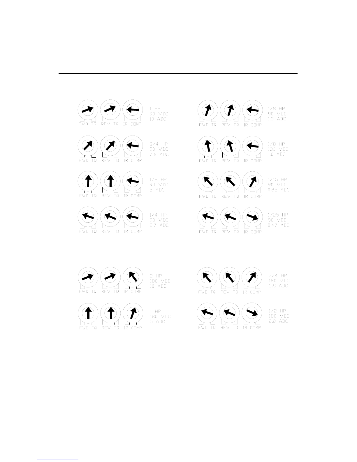
Figure 14. Typical FWD TQ, REV TQ, and IR COMP Settings
(actual settings may vary with each application)
RG400 Models
RG300 Models RG310 Models
Page 39

FWD ACC
The FWD ACC setting determines the time the motor takes to
ramp to either a higher speed in the forward direction or a
lower speed in the reverse direction, within the limits of
available torque. The FWD ACC setting is factory set for its
fastest forward acceleration time.
Turn the FWD ACC trimpot CW to increase the forward
acceleration time, and CCW to decrease the forward
acceleration time.
REV ACC
The REV ACC setting determines the time the motor takes to
ramp to either a higher speed in the reverse direction or a
lower speed in the forward direction, within the limits of
available torque. The REV ACC setting is factory set for its
fastest reverse acceleration time.
Turn the REV ACC trimpot CW to increase the reverse
acceleration time, and CCW to decrease the reverse
acceleration time.
31
Calibration
Page 40
32
Calibration
DB
The deadband trimmer potentiometer determines the time that
will elapse between the application of current in one direction
before current is applied in the opposite direction.
The deadband trimmer potentiometer affects the
resistance that a motor has to changes in shaft position at
zero speed. It does this by applying AC voltage to the
motor armature.
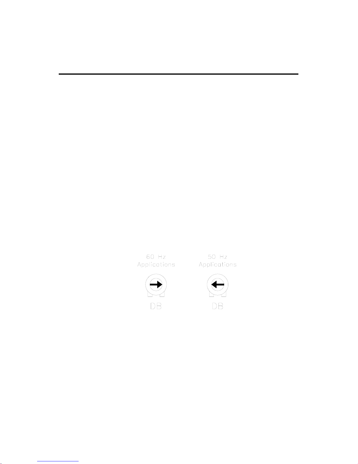
Deadband is factory calibrated to approximately the
3 o’clock position for 60 Hz AC line operation. Recalibrate
the deadband to the 9 o’clock position for 50 Hz AC line
operation. See Figure 15 for deadband settings.
Figure 15. Deadband Settings
Page 41
33
Application Notes
Connection to other Minarik devices
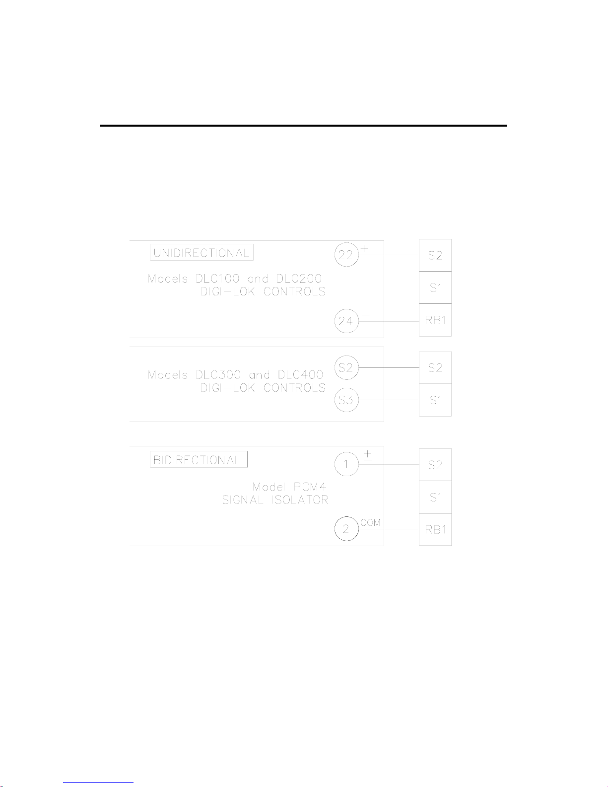
Figure 16. RG300/RG400 Series Connection to
DLC100(DLC200), DLC300(DLC400),
and PCM4
Page 42
34
Application Notes
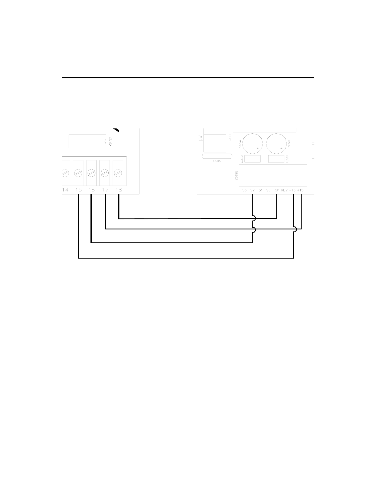
Figure 17. RG300/RG400 Series connection to 200-0386A
Limit Switch Logic Board
RG300/RG400 Series
200-0386A
Page 43
35
Application Notes
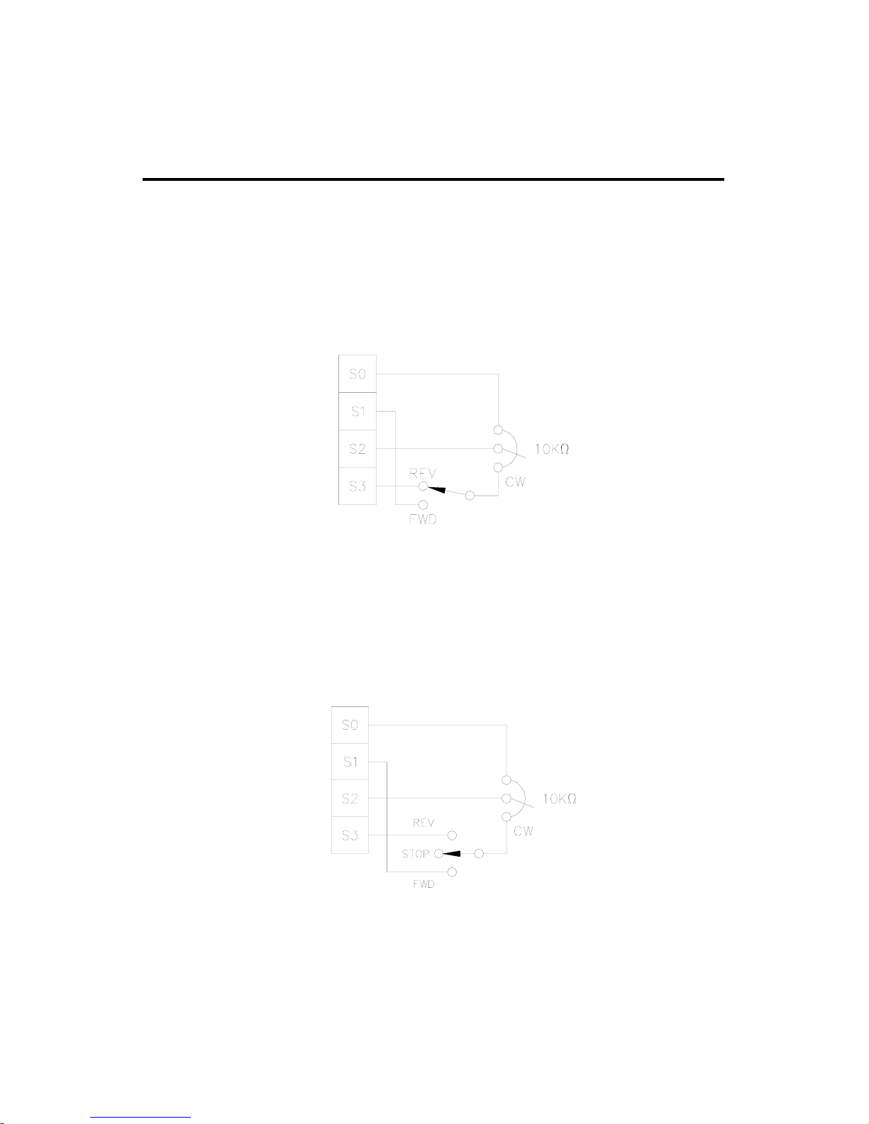
Use a single pole, two position switch with a single speed
adjust potentiometer to plug reverse the motor (Figure 18).
The MIN SPD setting is in effect for either direction.
Use a single pole, three position switch with a single speed
adjust potentiometer to stop a motor between reversals (Figure
19). Set the switch to the center position to decelerate the
motor to a stop.
Optional speed adjust potentiometer connections
Figure 18. Forward-Reverse Switch
Figure 19. Forward-Stop-Reverse Switch
Page 44
36
Application Notes
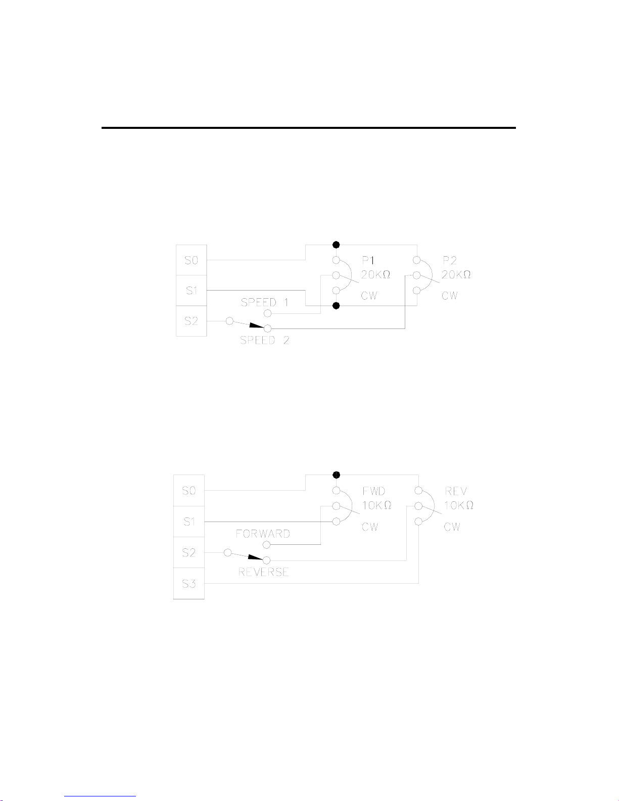
Connect two speed adjust potentiometers with a single pole
two position switch to select between two independent speeds
shown in the forward direction (Figure 20). The speed adjust
potentiometers can be mounted at two separate operating
stations.
Connect two speed adjust potentiometers as shown in Figure
21 to select between independent forward and reverse speeds.
Figure 20. Independent Adjustable Speeds
(Forward Direction)
Figure 21. Independent Forward and Reverse Speeds
Page 45
37
Application Notes
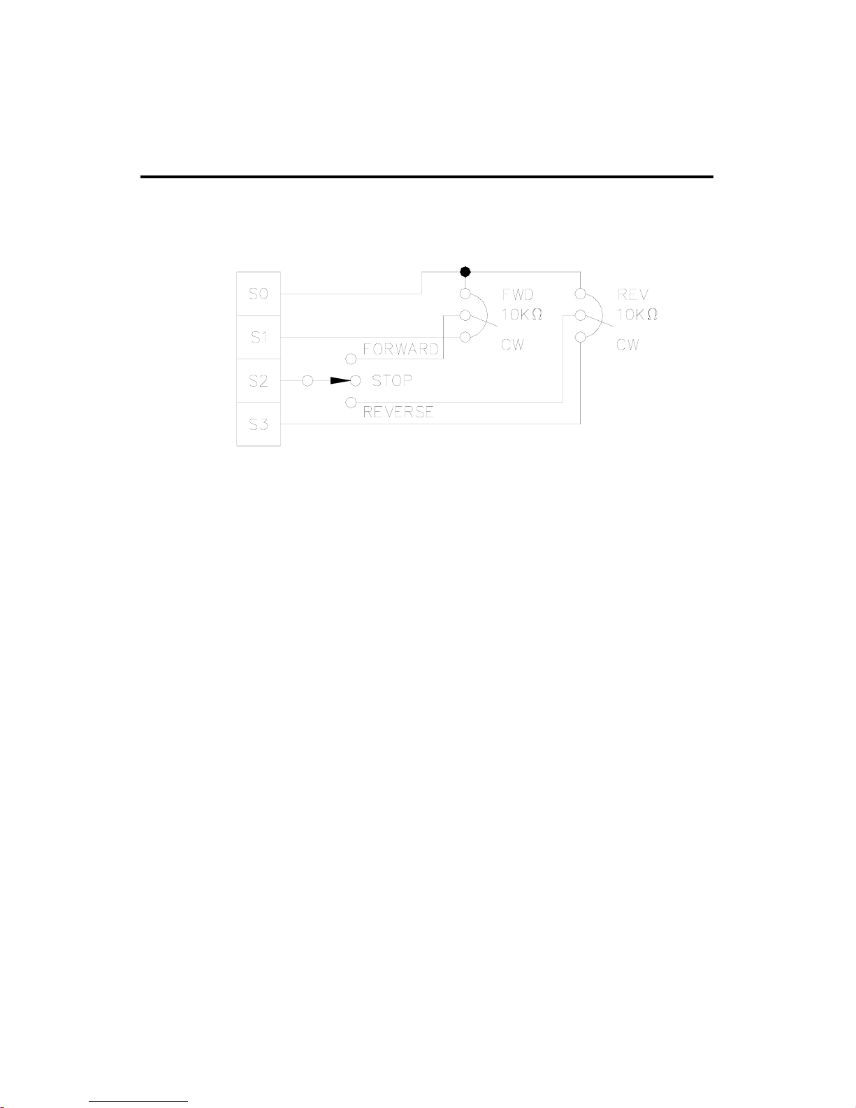
Use a single pole, three position switch to stop the motor
when the switch is in the center position (Figure 22).
Figure 22. Independent Forward and Reverse Speeds
with a Forward-Stop-Reverse Switch
Page 46

38
Troubleshooting
m Warning
Dangerous voltages exist on the drive when it is powered. When
possible, disconnect the drive while troubleshooting. High
voltages can cause serious or fatal injury.
Check the following steps before proceeding:
1. The AC line voltage must be balanced, and match the voltage
on the drive nameplate.
2. The deadband (DB) must be set approximately at the
3 o’clock position for 60 Hz AC line frequency or at
9 o’clock for 50 Hz AC line frequency.
3. The motor must be rated for the drive’s rated armature (all
motors) and field outputs (shunt wound motors only).
4. Do not make any connections to F1 and F2 if using a
permanent magnet motor.
5. Terminal block connections should be consistent with the
connections shown in this manual.
6. Check that line fuse FU501 (and FU502 for 230 VAC line
voltage) is properly sized and not blown.
7. Check that field fuse FU503 is 1.5 A and not blown.
Page 47

39
Troubleshooting
Problem
Field fuse blows
Line fuse blows
Possible
Causes
1. Field fuse is the
wrong size
2. Motor field is shorted
to ground
3. F1 is shorted to F2
4. Motor cable is
shorted to ground
5. Motor field leads are
reversed with motor
armature leads.
1. Line fuse is the
wrong size.
2. Motor cable or
armature is shorted to
ground.
3. Nuisance tripping
caused by a
combination of ambient
conditions and highcurrent spikes (i.e.
reversing).
Suggested
Solutions
1. Verify that the fuse is
1.5 A.
2. Check if the motor field
is shorted to ground.
Replace motor if
necessary.
3. Check that F1 and F2
are not shorted together.
4. Check that the motor
cable is not shorted to
ground. Replace cable if
necessary.
5. Wire motor armature to
A1 and A2; wire motor
field to F1 and F2.
1. Check that the line
fuses are correct for the
motor size (page 22).
2. Check motor cable and
armature for shorts.
3. Add a blower to cool
the drive components;
decrease FWD TQ and
REV TQ settings, or
resize motor and drive for
actual load demand, or
check for incorrectly
aligned mechanical
components or “jams”.
Page 48
40
Troubleshooting
Possible
Causes
1. Speed adjust
potentiometer or voltage
input signal set to zero
speed.
2. Speed adjust
potentiometer or voltage
input signal not
connected to drive input
properly; connections
are open.
3. REGEN BRAKE
(INHIBIT terminals) is
jumpered.
4. S2 is shorted to S1.
5. Drive is in current
limit.
6. Drive is not receiving
AC line voltage.
7. Motor is not
connected.
Suggested
Solutions
1. Increase the speed
adjust potentiometer or
voltage setting.
2. Check connections to
input. Verify that
connections are not
open.
3. Remove jumper from
the INHIBIT terminals.
4. Remove short.
5. Verify that motor is
not jammed. Increase
FWD TQ or REV TQ
setting, they are set too
low.
6. Apply AC line
voltage to L1 and L2.
7. Connect motor to A1
and A2.
Problem
Line fuse does not
blow, but the motor
does not run.
Page 49

41
Troubleshooting
Possible
Causes
1. MIN SPD and MAX
SPD not calibrated.
2. Field not operating
properly.
1. MAX SPD setting is
too low.
2. IR COMP setting is
too low.
3. Motor is overloaded.
1. IR COMP is set too
high.
2. Motor bouncing in
and out of TORQUE
limit.
Suggested
Solutions
1. Calibrate MIN SPD
and MAX SPD.
2. Verify motor field
connections and voltage
(see page 19).
1. Increase MAX SPD
setting.
2. Increase IR COMP
setting.
3. Check motor load.
Resize the motor if
necessary.
1. Adjust the IR COMP
setting slightly CCW
until the motor speed
stabilizes.
2. Make sure motor is
not undersized for load;
adjust FWD TQ and
REV TQ trimpot CW.
Problem
Motor runs too slow or
too fast.
Motor will not reach
the desired speed.
Motor pulsates or
surges under load.
Page 50

42
Troubleshooting
Possible
Causes
Deadband setting is too
high.
Suggested
Solutions
Turn deadband (DB)
trimpot CCW until the
noise stops.
Problem
Motor makes a
humming or buzzing
noise.
For additional assistance, contact you local Minarik®Distributor,
or the factory direct: phone (818)502-1528; fax (818)502-0716.
Page 51
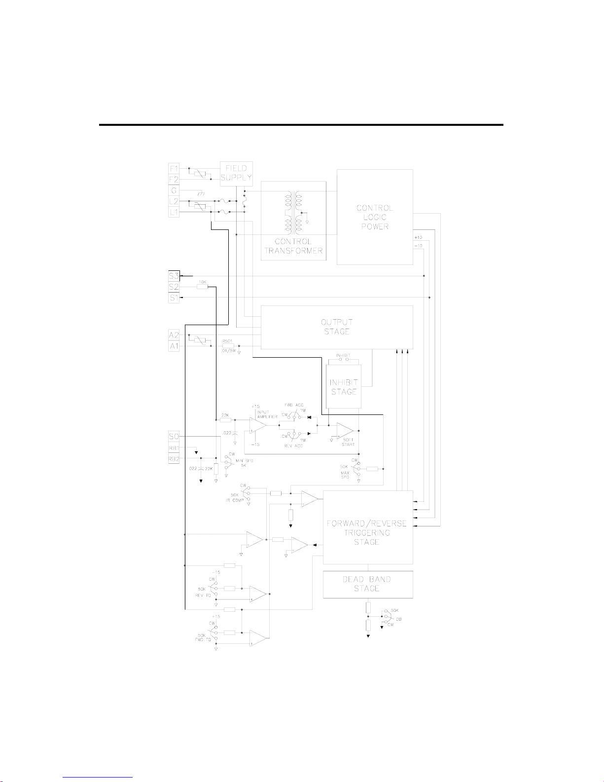
43
Figure 23. RG300 and RG400 Series Block Diagram
Block Diagram
Page 52
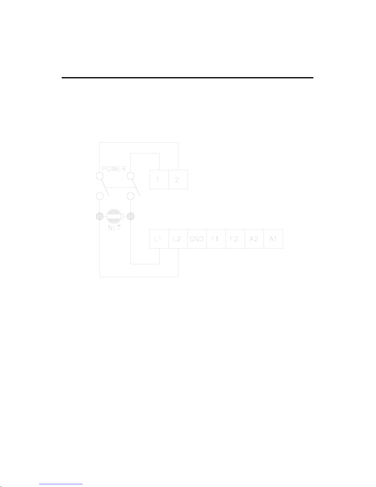
44
Factory Prewired Connections
(for Cased Drives)
Figure 24. Prewired Connections to L1 and L2
Page 53
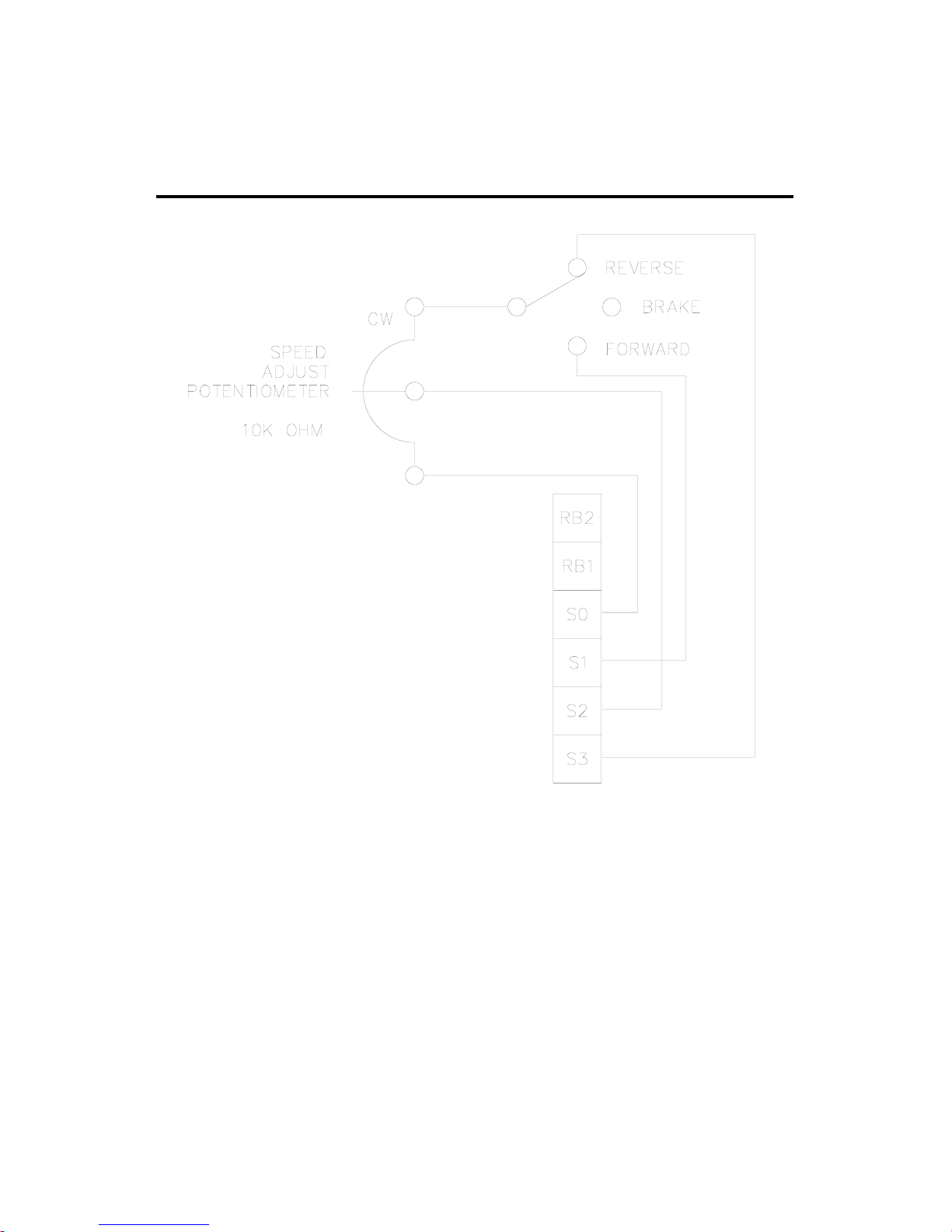
45
Factory Prewired Connections
Figure 25. Prewired Speed Adjust Potentiometer
Connections
Page 54

46
CE Compliance
Minarik Corporation hereby certifies that its RG300/RG400
series drives have been approved to bear the “CE” mark
provided the conditions of approval have been met by the end
user.
The RG300/RG400 series has been tested to the following test
specifications:
EN55011:1991 (emissions), and
EN50082-1:1992 (immunity)
Compliance allows Minarik’s RG300/RG400 series to bear the
CE mark.
The end user, as described herein, falls into one of two
categories:
1. The Consumer will deploy a stand-alone unit as an
integral, yet external, portion of the machine being
operated.
2. The Original Equipment Manufacturer (OEM) will
implement the product as a component of the machine
being manufactured.
In addition to EMI/RFI safeguards inherent in the
RG300/RG400 series’ design, external filtering is required.
Page 55

47
Line filters
Minarik requires the Corcom®line filters listed in Table 3. If
the exact filter is not available, the specifications are:
L = 0.88 milliHenries.
C = 0.30 microFarads (X); 0.011 microFarads (Y).
R = 680Kohms.
Rated current: 1.4 times maximum DC motor current.
Filter type: Balanced 2-section.
Table 3. Corcom®Filters
Nameplate Current of Corcom®Filter
Motor Wired to the Drive Part Number
0 to 4 amps 5VR1
4.1 to 13 amps 20VV1
The filters in Table 3 should be wired to the AC line within
0.25 meters of the drive. The ground connection from the
filter must be wired to solid earth ground (resistance less than
500 ohms); not machine ground. This is very important!
If the end-user is using a CE-approved motor, the correct filter
from Table 1 is all that is necessary to meet the EMC
directives listed herein.
CE Compliance
Page 56

Armature filters
If the end-user is not using a CE-approved motor, a CExxRG
filter must be used on the armature. “XX” refers to the rated
current of the filter.
The CE20RG is a Real-Pole Balanced-Pi 3-pole filter. If the
exact filter is not available, the specifications are as follows:
L & L1 = 2 * (0.8) milliHenries.
C & C1 = 2 * (0.1) microFarads @ 400W VDC.
Rin = 0.1 ohm; Rout = 1.2 ohm.
Table 4. Minarik®Filters
Nameplate Current of Minarik®Filter
Motor Wired to the Drive Part Number
0 to 4 amps CE04RG
4.1 to 13 amps CE20RG
The filters in Table 4 must be wired to the DC output of the
drive, as close to the drive as possible.
48
CE Compliance
Page 57

The end user must use the filters listed in this section to
comply with CE. The OEM may choose to provide alternative
filtering that encompasses the Minarik drive and other
electronics within the same panel.
The OEM has this liberty because CE is a machinery
directive. Whether or not every component in the OEM’s
machinery meets CE, the OEM must still submit his machine
for CE approval.
Thus, no component must necessarily meet CE within the
machine, as long as the OEM takes the necessary steps to
guarantee the machine does meet CE. By the same token, even
if every component in the OEM’s machine does meet CE, the
machine will not necessarily meet CE as a machine.
Using CE-approved wiring practices (like proper shielding)
and the filters listed in this section guarantee the drive will
meet EN55011 (1991 emissions standard) and EN50082-1
(1992 immunity standard).
49
CE Compliance
Page 58

50
Replacement Parts
Replacement parts are available from Minarik Corporation and its
distributors for this drive series.
Table 5. Replacement Parts
Model No. Symbol Description Minarik®P/N
RG310UA R501 0.1Ω, 5 W Resistor 032-0100
SCR501-508 800 V, 25 A SCR 072-0042
T505 3FS-436 Transformer 230-0071
10KΩ Potentiometer Kit 202-0003
Chassis 223-0258
8 A, 3AB Line Fuse 050-0023
1.5 A, 3AG Field Fuse 050-0026
Fuse Kit ( 3 – 8A) 050-0069
Fuse Kit (5 – 20A) 050-0073
Pico Fuse, 1/2 A 050-0064
RG310A Same parts as RG310UA except 202-0003 and 223-0258.
Include:
10KΩ, 2W Potentiometer 120-0047
Potentiometer Knob 140-0013
Case 223-0209
Green Neon Indicator 040-0043
FWD/BRAKE/REV Switch 080-0004
Power Switch 080-0022
Toggle Switch Boot 155-0050
Chassis 223-0260
Heat Sink 223-0232
RG310UA-S Same parts as RG310UA except
7-pin Terminal Block 160-0019
8-pin Terminal Block 160-0116
RG310A-S Same parts as RG310A except
7-pin Terminal Block 160-0019
8-pin Terminal Block 160-0116
Page 59

51
Replacement Parts
Table 5. Replacement Parts (Continued)
Model No. Symbol Description Minarik®P/N
RG300UA R501 0.01Ω, 5 W Resistor 032-0129
SCR501-508 800 V, 25 A SCR 072-0042
T505 3FS-436 Transformer 230-0071
10KΩ Potentiometer Kit 202-0003
Chassis 223-0258
20 A, 3AB Line Fuse 050-0019
1.5 A, 3AG Field Fuse 050-0026
Fuse Kit (3 – 8A) 050-0069
Fuse Kit (5 – 20A) 050-0073
Pico Fuse, 1/2 A 050-0064
RG300A Same parts as RG300UA except 202-0003 and 223-0258.
Include:
10KΩ, 1/2 W Potentiometer 120-0032
Potentiometer Knob 140-0013
Case 223-0209
Green Neon Indicator 040-0043
FWD/BRAKE/REV Switch 080-0004
Power Switch 080-0022
Toggle Switch Boot 155-0050
Chassis 223-0260
Heat Sink 223-0232
RG300UA-S Same parts as RG300UA except
7-pin Terminal Block 160-0019
8-pin Terminal Block 160-0116
RG300A-S Same parts as RG300A except
7-pin Terminal Block 160-0019
8-pin Terminal Block 160-0116
Page 60

52
Replacement Parts
Table 5. Replacement Parts (Continued)
Model No. Symbol Description Minarik®P/N
RG400UA R501 0.1Ω, 5 W Resistor 032-0129
SCR501-508 800 V, 25 A SCR 072-0042
T505 3FD-436 Transformer 230-0072
10KΩ Potentiometer Kit 202-0003
Chassis 223-0258
20 A, 3AB Line Fuse 050-0019
1.5 A, 3AG Field Fuse 050-0026
Fuse Kit ( 3 – 8A) 050-0069
Fuse Kit (5 – 20A) 050-0073
Pico Fuse, 1/2 A 050-0064
RG400A Same parts as RG400UA except 202-0003 and 223-0258.
Include:
10KΩ, 2 W Potentiometer 120-0047
Potentiometer Knob 140-0013
Case 223-0209
Green Neon Indicator 040-0005
FWD/BRAKE/REV Switch 080-0043
Power Switch 080-0022
Toggle Switch Boot 155-0050
Chassis 223-0260
Heat Sink 223-0232
RG400UA-S Same parts as RG400UA except
7-pin Terminal Block 160-0019
8-pin Terminal Block 160-0116
RG400A-S Same parts as RG400A except
7-pin Terminal Block 160-0019
8-pin Terminal Block 160-0116
Page 61

Notes
53
Page 62

Notes
54
Page 63

Limited Warranty
A. Warranty - Minarik Corporation (referred to as “the Corporation”) warrants that its products will
be free from defects in workmanship and material for two (2) years from date of shipment thereof,
or 6,000 hours, whichever comes first. Within this warranty period, the Corporation will repair or
replace such products that are: (1) returned to Minarik Corporation, 901 East Thompson Avenue,
Glendale, CA 91201-2011 USA; and, (2) determined by the Corporation to be defective.
This warranty shall not apply to any product that has been subject to misuse, negligence, or
accident; or misapplied; or repaired by unauthorized persons; or improperly installed. The
Corporation is not responsible for removal, installation, or any other incidental expenses incurred
in shipping the product to and from the repair point.
B. Disclaimer - The provisions of Paragraph A are the Corporation’s sole obligation and exclude
all other warranties of merchantability for use, express or implied. The Corporation further
disclaims any responsibility whatsoever to the customer or to any other person for injury to the
person or damage or loss of property of value caused by any product that has been subject to
misuse, negligence, or accident, or misapplied or modified by unauthorized persons or improperly
installed.
C. Limitations of Liability - In the event of any claim for breech of any of the Corporation’s
obligations, whether express or implied, and particularly of any other claim or breech of warranty
contained in Paragraph A, or of any other warranties, express or implied, or claim of liability that
might, despite Paragraph B, be decided against the Corporation by lawful authority, the
Corporation shall under no circumstances be liable for any consequential damages, losses, or
expense arising in connection with the use of, or inability to use, the Corporation’s product for any
purpose whatsoever.
An adjustment made under warranty does not void the warranty, nor does it imply an extension of
the original two (2) year or 6,000 hour warranty period. Products serviced and/or parts replaced on
a no-charge basis during the warranty period carry the unexpired portion of the original warranty
only.
If for any reason any of the foregoing provisions shall be ineffective, the Corporation’s liability for
damages arising out of its manufacture or sale of equipment, or use thereof, whether such liability
is based on warranty , contract, negligence, strict liability in tort, or otherwise, shall not in any event
exceed the full purchase price of such equipment.
Any action against the Corporation based upon any liability or obligation arising hereunder or
under any law applicable to the sale of equipment or the use thereof, must be commenced within
one year after the cause of such action arises.
Page 64

901 East Thompson Avenue
Glendale, California 91201-2011
Phone: (818) 502-1528
Fax: (818) 502-0716
www.minarikcorp.com
Document number 250–0167, Revision 2
Printed in the U.S.A – 2/98
North America $12.00, Outside North America $15.00
 Loading...