

Minarik RG25U, RG51UA User Manual
RG Series
Models:
RG25U
RG51UA
SCR, Adjustable-Speed
Regenerative Drives
for DC Brush Motors
User’s Manual

Copyright 1998 by
Minarik Corporation
All rights reserved. No part of this manual may be reproduced or transmitted in
any form without written permission from Minarik Corporation. The information
and technical data in this manual are subject to change without notice. Minarik
Corporation and its Divisions make no warranty of any kind with respect to this
material, including, but not limited to, the implied warranties of its merchantability
and fitness for a given purpose. Minarik Corporation and its Divisions assume no
responsibility for any errors that may appear in this manual and make no
commitment to update or to keep current the information in this manual.
Printed in the United States of America.

m Safety Warnings
• This symbol m denotes an important safety tip or warning.
Please read these sections carefully prior to performing any of
the instructions contained in that section.
• Have a qualified electrical maintenance technician install,
adjust and service this equipment. Follow the National
Electrical Code and all other applicable electrical and safety
codes, including the provisions of the Occupational Safety
and Health Act (OSHA), when installing equipment.
• Reduce the chance of an electrical fire, shock, or explosion by
proper grounding, over-current protection, thermal protection,
and enclosure. Follow sound maintenance procedures.
• It is possible for a drive to run at full speed as a result of a
component failure. Please ensure that a master switch has
been placed in the AC line to stop the drive in an emergency.
• This drive is isolated from earth ground. Circuit potentials
are at 115 VAC above earth ground. Avoid direct contact with
the printed circuit board or with circuit elements to prevent the
risk of serious injury or fatality. Use a non-metallic screwdriver
for adjusting the calibration trimpots.

ii
Contents
Specifications 1
Dimensions 2
Regenerative Drives 4
Installation 6
Mounting drives . . . . . . . . . . . . . . . . . . . . . . . . . . . . . . . . . . . . . . . . . . . . .6
Line fusing . . . . . . . . . . . . . . . . . . . . . . . . . . . . . . . . . . . . . . . . . . . . . . . . .7
Screw terminal block . . . . . . . . . . . . . . . . . . . . . . . . . . . . . . . . . . . . . . . . . .8
Spade lugs . . . . . . . . . . . . . . . . . . . . . . . . . . . . . . . . . . . . . . . . . . . . . . . . .8
Speed adjust potentiometer installation . . . . . . . . . . . . . . . . . . . . . . . . . . . .9
RG25U Connections . . . . . . . . . . . . . . . . . . . . . . . . . . . . . . . . . . . . . . . . .10
AC line and motor connections . . . . . . . . . . . . . . . . . . . . . . . . . . . . . .10
Speed adjust potentiometer connections . . . . . . . . . . . . . . . . . . . . . .11
RG51UA Connections . . . . . . . . . . . . . . . . . . . . . . . . . . . . . . . . . . . . . . . .12
AC line, motor, and field connections . . . . . . . . . . . . . . . . . . . . . . . . .12
Speed adjust potentiometer connections . . . . . . . . . . . . . . . . . . . . . .13
Block Diagram . . . . . . . . . . . . . . . . . . . . . . . . . . . . . . . . . . . . . . . . . . . . . . . . .14
Operation 16
Before applying power . . . . . . . . . . . . . . . . . . . . . . . . . . . . . . . . . . . . . . .16
Startup . . . . . . . . . . . . . . . . . . . . . . . . . . . . . . . . . . . . . . . . . . . . . . . . . . .16
Line starting and line stopping . . . . . . . . . . . . . . . . . . . . . . . . . . . . . . . . . .16
Automatic restart upon power restoration . . . . . . . . . . . . . . . . . . . . . . . . .17
Regenerative deceleration (RG25U) . . . . . . . . . . . . . . . . . . . . . . . . . . . . .17
Regenerative deceleration (RG51UA) . . . . . . . . . . . . . . . . . . . . . . . . . . . .18
Warning . . . . . . . . . . . . . . . . . . . . . . . . . . . . . . . . . . . . . . . . . . . . . . . . . .18

Calibration 19
MAX SPD . . . . . . . . . . . . . . . . . . . . . . . . . . . . . . . . . . . . . . . . . . . . . . . . .19
FWD TQ . . . . . . . . . . . . . . . . . . . . . . . . . . . . . . . . . . . . . . . . . . . . . . . . . .19
REV TQ . . . . . . . . . . . . . . . . . . . . . . . . . . . . . . . . . . . . . . . . . . . . . . . . . .20
IR COMP . . . . . . . . . . . . . . . . . . . . . . . . . . . . . . . . . . . . . . . . . . . . . . . . .20
DB . . . . . . . . . . . . . . . . . . . . . . . . . . . . . . . . . . . . . . . . . . . . . . . . . . . . . .22
Application Notes 23
RG25U/RG51UA Connections to other Minarik devices . . . . . . . . . . . . . .23
Optional speed adjust potentiometer connections . . . . . . . . . . . . . . . . . . .24
Troubleshooting 29
Replacement Parts 32
CE Compliance for RG51UA 33
Limited Warranty inside back cover
iii

Illustrations
Fig Description Page
1. RG25U Dimensions . . . . . . . . . . . . . . . . . . . . . . . . . . . . . . . . . . . . . . . . . .2
2. RG51UA Dimensions . . . . . . . . . . . . . . . . . . . . . . . . . . . . . . . . . . . . . . . . .3
3. Four-Quadrant Operation . . . . . . . . . . . . . . . . . . . . . . . . . . . . . . . . . . . . . .5
4. Screw Terminal Block . . . . . . . . . . . . . . . . . . . . . . . . . . . . . . . . . . . . . . . . .8
5. Speed Adjust Potentiometer Installation . . . . . . . . . . . . . . . . . . . . . . . . . . .9
6. RG25U AC Line and Motor Connections . . . . . . . . . . . . . . . . . . . . . . . . . .10
7a. RG25U Connection for Unidirectional Operation . . . . . . . . . . . . . . . . . . . .11
7b. RG25U Connection for Bidirectional Operation . . . . . . . . . . . . . . . . . . . . .11
8. RG51UA AC Line, Motor and Field Connections . . . . . . . . . . . . . . . . . . . .12
9a. RG51UA Connection for Unidirectional Operation . . . . . . . . . . . . . . . . . . .13
9b. RG51UA Connection for Bidirectional Operation . . . . . . . . . . . . . . . . . . . .13
10. RG25U/RG51UA Series Block Diagram . . . . . . . . . . . . . . . . . . . . . . . . . .14
11. RG25U Regenerative Deceleration Switch . . . . . . . . . . . . . . . . . . . . . . . .17
12. RG51UA Regenerative Deceleration Switch . . . . . . . . . . . . . . . . . . . . . . .18
13. Typical FWD TQ, REV TQ and IR COMP Settings . . . . . . . . . . . . . . . . . . .21
14. Deadband Settings . . . . . . . . . . . . . . . . . . . . . . . . . . . . . . . . . . . . . . . . . .22
15. RG25U/RG51UA Connection to Other Minarik Devices . . . . . . . . . . . . . . .23
16. Forward-Reverse Switch . . . . . . . . . . . . . . . . . . . . . . . . . . . . . . . . . . . . . .24
17. Forward-Stop-Reverse Switch . . . . . . . . . . . . . . . . . . . . . . . . . . . . . . . . . .25
18. Independent Adjustable Speeds . . . . . . . . . . . . . . . . . . . . . . . . . . . . . . . .26
19. Independent Forward and Reverse Speeds . . . . . . . . . . . . . . . . . . . . . . . .27
20. Independent Forward and Reverse Speeds with FWD-STOP-REV Switch .28

Tables
Fig Description Page
1. Line Fusing for RG Series Drives . . . . . . . . . . . . . . . . . . . . . . . . . . . . . . . .7
2. Replacement Parts . . . . . . . . . . . . . . . . . . . . . . . . . . . . . . . . . . . . . . . . . .32
3. AC Line Filters . . . . . . . . . . . . . . . . . . . . . . . . . . . . . . . . . . . . . . . . . . . . .34
4. Armature Filters . . . . . . . . . . . . . . . . . . . . . . . . . . . . . . . . . . . . . . . . . . . .35
vvi1


Specifications
Max.
Armature HP Range
Model (Amps DC) Applied
RG25U 5.0 1/8–1/2
RG51UA 5.0 1/8–1/2
AC Line Voltage 115 VAC, ±10%, 50/60 Hz, single phase
Peak Current Limit 9 ADC
Maximum Armature Voltage Range at 115 VAC Input 60–75 VDC
Form Factor 1.77 at base speed
Acceleration Time (with load) 1 second
Deceleration Time (with load) 1 second
Speed Adjust Potentiometer 50KΩ
Analog Input Voltage Range (isolated; S1 to S2) 0–10 VDC
Input Impedance (S0 to S2) RG25U 200KΩ
Load Regulation at Base Speed 3%
Speed Range 50:1
Weight - RG25U .50 lb (227 grams)
Weight - RG51UA .75 lb (340 grams)
Ambient Temperature Range 10°C–55°C
Vibration 0.5g max (0 – 50 Hz)
RG51UA ONLY
Field Voltage (F1 to F2) 100 VDC
Maximum Field Current 1 ADC
Current with 115 VAC
RG51UA 100KΩ
0.1g max (above 50 Hz)
2
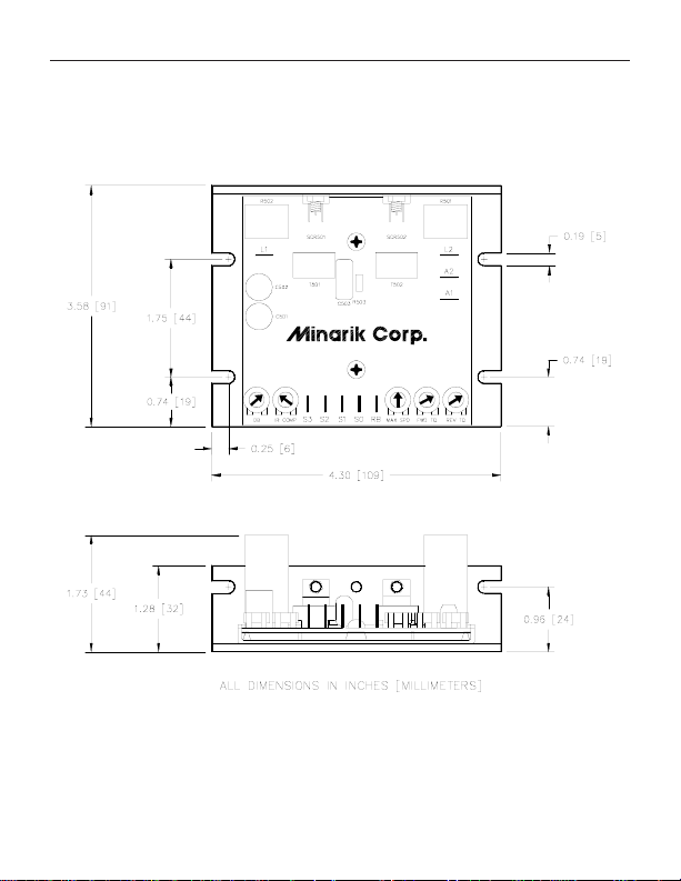
Dimensions
Figure 1. RG25U Dimensions
Dimensions
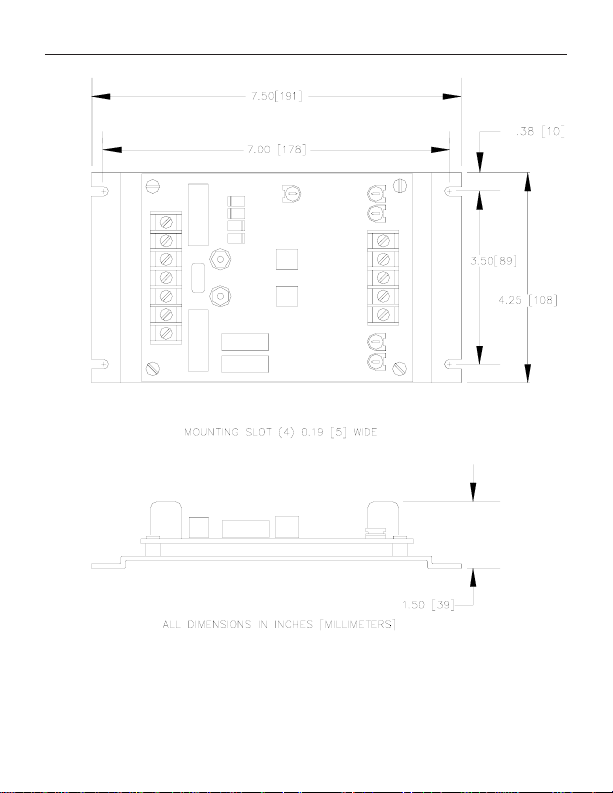
3
Figure 2. RG51UA Dimensions

4
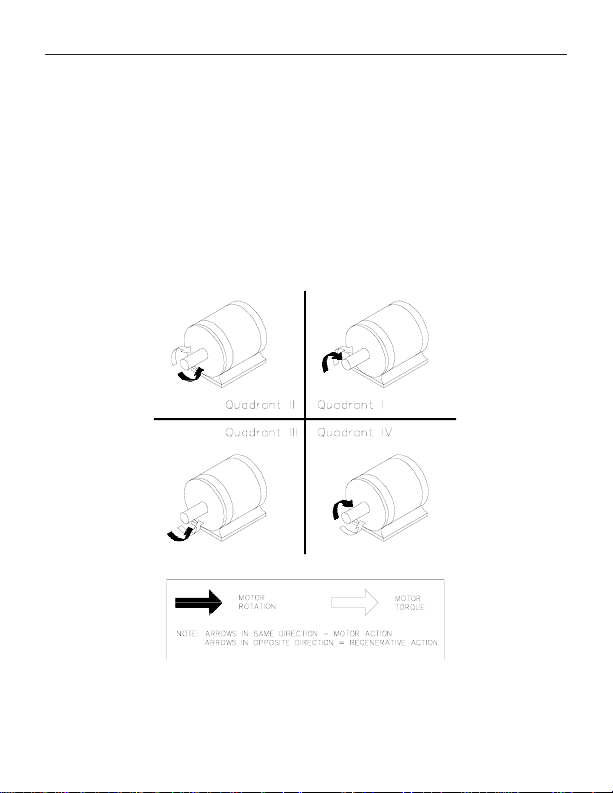
Regenerative Drives
Most non-regenerative, variable speed, DC drives control
current flow to a motor in one direction. The direction of
current flow is the same direction as the motor rotation.
Non-regenerative drives operate in Quadrant 1, and also in
Quadrant 3 if the drive is reversible (Figure 3). Motors must
stop before reversing direction. Unless dynamic braking is
used, non-regenerative drives cannot oppose an overhauling
load, and cannot decelerate a load faster than coasting to a
lower speed.
Regenerative drives operate in two additional quadrants:
Quadrant 2 and Quadrant 4. In these quadrants, motor torque
is in the opposite direction of motor rotation.
Regenerative drives can reverse a motor without contactors,
switches, brake resistors, and inhibit plugs. They can also
control an overhauling load and decelerate a load faster than it
would take to coast to a lower speed.
The RG25U and the RG51UA are regenerative drives. They
are uncased chassis model drives and designed to be installed
in original equipment. The drives are the same electrically.
The physical layout and size of these drives are different (see
Dimensions section). The RG51UA includes a field supply for
shunt wound motors.
The RG25U and the RG51UA are half wave rectified DC
regenerative drives. Therefore the maximum armature voltage
Regenerative Drives
of these drives is 75 VDC. This means that a 90 VDC motor
will only run at about 83% of rated nameplate speed.
The form factor of the RG25U and the RG51UA is 1.77. This
will cause a higher-than-normal heating in the motor
armature. To prevent a shorter-than-normal motor life,
Minarik recommends that the horsepower rating of the motor
for a given application be at least 50% greater than the
required horsepower.
5
Figure 3. Four Quadrant Operation

6
Installation
ASSUMPTIONS: Minarik drives supply motor voltage from
A1 (or A+) and A2 (or A–) terminals. It is assumed
throughout this manual that, when A1 (or A+) is positive with
respect to A2 (or A–), the motor will rotate clockwise (CW)
while looking at the output shaft protruding from the front of
the motor. If this is opposite of the desired rotation, simply
reverse the wiring of A1 (or A+) and A2 (or A–) with each
other.
Mounting drives
Drive components are sensitive to electrostatic fields. Avoid
contact with the circuit board directly. Hold the drive by the
chassis only.
Protect the drive from dirt, moisture, and accidental contact.
Provide sufficient room for access to the terminal block and
calibration trimpots.
Mount the drive away from other heat sources. Operate
the drive within the specified ambient operating temperature
range.
Prevent loose connections by avoiding excessive vibration
of the drive.

Installation
Mount the drive with its board in either a horizontal or
vertical plane. The RG25U has six 0.188 inch (4.8 mm) wide
slots in the chassis that accept #8 pan head screws. Fasten
either the large base or the narrow flange of the chassis to the
subplate. The RG51UA has four 0.188 inch (4.8mm) wide
slots in the base of the chassis that accept #8 pan head screws.
The chassis must be earth grounded for noise suppression. To
ground the RG51UA chassis, connect earth ground to the
GND terminal on the seven position terminal block.
To ground the RG25U use a star washer beneath the head of at
least one of the mounting screws to penetrate the anodized
chassis surface and to reach bare metal.
Line fusing
The National Electrical Code requires the installation of a
circuit breaker or fuse on the incoming AC line voltage. Use a
circuit breaker or fast acting fuse rated for 8 amps or less.
With an 115VAC line voltage fuse the hot leg of the AC line
that connects to L1 and leave L2 unfused. Use 250VAC fuses.
See Table 1 for recommended line fuse sizes.
Table 1. Recommended Line Fuse Sizes
90 VDC Maximum Armature Fuse
Motor HP Current Rating
1/8 1.5 3
1/4 2.6 5
1/3 3.5 8
1/2 5.0 8
7
 Loading...