

Page 1

USER’S MANUAL
Models:
MAC05–D240AC
MAC08–D240AC
MAC05–D240AC-PCM
MAC08–D240AC-PCM
Variable-frequency drives for 3-phase AC motors
MAC Series
Page 2

Copyright 2001 by
Minarik Corporation
All rights reserved. No part of this manual may be reproduced or transmitted in any
form without written permission from Minarik Corporation. The information and
technical data in this manual are subject to change without notice. Minarik
Corporation and its Divisions make no warranty of any kind with respect to this
material, including, but not limited to, the implied warranties of its merchantability
and fitness for a given purpose. Minarik Corporation and its Divisions assume no
responsibility for any errors that may appear in this manual and make no
commitment to update or to keep current the information in this manual.
Printed in the United States of America.
Page 3

Safety Warnings
• This symbol denotes an important safety tip or warning.
Please read these instructions carefully before performing
any of the procedures contained in this manual.
• DO NOT INSTALL, REMOVE, OR REWIRE THIS
EQUIPMENT WITH POWER APPLIED. Have a qualified
electrical technician install, adjust and service this equipment.
Follow the National Electrical Code and all other applicable
electrical and safety codes, including the provisions of the
Occupational Safety and Health Act (OSHA), when installing
equipment.
• Reduce the chance of an electrical fire, shock, or explosion by
proper grounding, over-current protection, thermal protection,
and enclosure. Follow sound maintenance procedures.
i
It is possible for a drive to run at full speed as a result of
a component failure. Minarik strongly recommends the
installation of a master switch in the main power input to
stop the drive in an emergency.
Circuit potentials are at 115 VAC or 230 VAC above earth
ground. Avoid direct contact with the printed circuit board or
with circuit elements to prevent the risk of serious injury or
fatality. Use a non-metallic screwdriver for adjusting the
calibration trimpots. Use approved personal protective
equipment and insulated tools if working on this drive with
power applied.
Page 4

Specifications 1
Dimensions 2
Installation 3
Mounting ...................................................3
Wiring .....................................................4
Shielding guidelines . . . ......................................5
Isolation (-PCM drives only) . ...................................6
Fusing ....................................................6
Heat sinking ................................................6
Speed adjust potentiometer .....................................7
Cage-clamp terminals . . . ......................................8
Connections . ................................................9
Power and fuse connections .................................10
Motor connections . . . . . . ..................................13
Three-phase motors . . . . . . .................................15
Operation 17
Voltage doubler .............................................18
To enable voltage doubling: .................................19
Before applying power . . . . . . .................................20
Startup ....................................................21
To reverse motor direction: ..................................22
Starting and stopping methods .................................23
Braking . . . ..............................................23
To coast the motor to a stop without disconnecting power: ..........23
I²T trip operation (class 10 characteristics) ......................24
Line starting and line stopping ...............................24
Decelerate to minimum speed ...............................25
Decelerate to minimum with DC injection braking .................26
Drive thermal protection ......................................28
ii
Contents
Page 5

Thermal protection of the motor ..............................28
Calibration 30
Calibration Procedure Setup for 60 Hz Motors (See Figure 12): .........34
MINIMUM SPEED (MIN SPD) ...............................36
MAXIMUM SPEED (MAX SPD) ...............................36
CURRENT LIMIT (I LIMIT) ..................................36
SLIP COMPENSATION (SLIP COMP) .........................37
ACCELERATION/DECELERATION (ACCEL/DECEL) ..............37
Torque Boost Adjustment ...................................38
Application Notes 40
Thermal Protection Switch Installation ............................40
Independent adjustable speeds with .............................41
FWD-REV switch ...........................................41
RUN/JOG switch ............................................42
Single speed potentiometer control of multiple motors ................43
Reversing . . . ..............................................44
Voltage follower ............................................45
Troubleshooting 46
Before troubleshooting . . . . . . .................................46
Diagnostic LEDs ............................................47
POWER ON (green) . . . . . . .................................47
FAULT (red) ...............................................
TRIP I²T (red) . . ............................................
REV (amber) ...............................................
FWD (amber) . . ............................................
TQ LIM (red) ............................................48
Clearing LED fault indications ..................................52
Replacement Parts ..........................................58
Unconditional Warranty inside back cover
iiiTable of Contents
Page 6

Figure 1. Dimensions . . . . . . ....................................2
Figure 2. Speed Adjust Potentiometer ..............................7
Figure 3. Cage-Clamp Terminal ...................................8
Figure 4. Power and Fuse Connections ............................10
Figure 5. Signal and Optional Switch Connections ....................12
Figure 6. Motor Connections for Single-Phase Operation ..............14
Figure 7. Motor Connections for Three-Phase Motors .................16
Figure 8. Voltage Doubler Terminals ..............................19
Figure 9. Run/Decelerate to Minimum Speed Switch ..................25
Figure 10. RUN-BRAKE switch with optional ENABLE-DISABLE Switch ....27
Figure 11. Thermal Overload Switch with Optional Enable/Disable Switch . . .29
Figure 12. Calibration Trimpot Layout ..............................31
Figure 13. DIP Switch Layout and Initial Settings ......................32
Figure 14. Carrier Frequency Mode DIP Switch Layout .................35
Figure 15. Accel Torque Boost DIP Switch Setting .....................39
Figure 16. Thermal Overload Protection Switch Installation ..............40
Figure 17. Thermal Overload Protection Switch Installation
With Optional Enable/Disable Switch .......................40
Figure 18. Independent Adjustable Speeds ..........................41
Figure 19. RUN/JOG Switch . . . ..................................42
Figure 20. Single Speed Potentiometer Control of Multiple Motors .........43
Figure 21. Reversing Circuit Connection ............................44
Figure 22. Voltage Follower Connections ............................45
Figure 23. Diagnostic LED Layout .................................49
iv
Illustrations
Page 7

Table 1. Motor Phase DIP Switch Settings .........................15
Table 2. Voltage Doubler Configuration ...........................19
Table 3. Max Frequency DIPSwitch Settings .......................33
Table 4. Carrier Frequency DIPSwitch Settings .....................35
Table 5. Accel Torque Boost DIP Switch Settings ....................39
Table 6. Replacement Parts ...................................58
v
Tables
Page 8

vi
*Actual minimum frequency will depend on motor type and the load to which it is
connected.
General Information
Minarik MAC Series drives are voltage-vector-controlled,
microprocessor-based, variable-frequency AC motor drives. With
a 115 or 230 VAC, 50/60 Hz, single-phase input, MAC drives are
factory calibrated for an output of 0* to 60 Hz. They will operate
any 1 HP or smaller, 115- or 208/230-volt, three-phase AC
induction motor through a speed range of zero* through
nameplate speed. They can be user calibrated for 0* through 400
Hz output.
Using proprietary power-control circuitry, the MAC can also
double the input line voltage. This allows users to plug the MAC
into a 115 VAC line, but control a 208/230 VAC motor.
Although MAC inverters can operate over a 100:1 speed range,
most motors will operate over a 10:1 speed range with constant
torque at 0* to 60 Hz and constant horsepower above 60 Hz.
(Inverter-duty motors may operate satisfactorily over a 20:1 speed
range.) Some motors can be satisfactorily operated at speeds as
low as 100 rpm (speed range 25:1). Below 100 rpm, some
motors may show signs of “stepping” or “cogging”, or they may
run warmer.
Page 9

†
In silent mode.
viiGeneral Information
The MAC carrier frequency is true 16.5 kHz.† Many AC drive
manufacturers count the leading and trailing edge of the
modulated signal, thereby doubling the published carrier
frequency; however, their fundamental frequency is only half
(8 kHz in this case). By this method, the MAC’s carrier
frequency would be 33 kHz. The MAC is one of the only drives
on the market with truly silent operation.
MAC Series drives feature solid-state reversing with adjustable
acceleration and deceleration. They also feature adjustable
current limit and I²T class 10 current trip to protect the motor, the
control and the driven machine from damage caused by motor
overload or machine jamming. The MAC may also interface with
motor thermal protection through the enable circuit.
Many 3-phase inverter manufacturers claim that they can run
single-phase motors effectively. This is normally accomplished
by wiring only 2 phases; however, this primitive method may
cause instabilities due to the lack of feedback from one of the
motor connections. Furthermore, motor torque will be reduced
considerably because the phases are still 120º apart. The MAC
can efficiently operate a single-phase motor because the ASIC
changes the phase shift to 90º in order to develop maximum
torque.
Page 10

Caution should be taken when operating fan-cooled motors
at low speeds because their fans may not move sufficient air
to properly cool the motor. Minarik recommends “inverterduty” motors when the speed range is beyond 10:1.
viii
General Information
The following motor types MAY NOT be used:
• Split phase
• Capacitor start
• Repulsion induction
• Series Universal AC/DC
• Any motor with starting switch (centrifugal or relay) and/or
separate starting winding.
The MAC is very efficient when the two (2) torque boost settings
are properly adjusted; the accel torque boost is applied only
during acceleration. Other drives, with only one torque boost
setting, can cause motor overheating by applying too much during
steady-state operating conditions.
IMPORTANT INFORMATION
In addition to standard 3-phase induction motors, the following
motor types may be used with the MAC:
• Permanent split capacitor (PSC)
• Shaded pole
• AC synchronous
• AC stepping: 28.8, 72 and 200-RPM type.
Page 11

MAC Series Features
• Microprocessor-based
• Voltage-vector-control drive
• True 16.5 kHz carrier frequency (in silent mode)
• Solid-state circuitry
• Adjustable minimum and maximum speed
• Adjustable acceleration and deceleration
• Solid-state reversing
• Adjustable current limit
•I²T current trip (class 10)
• Adjustable torque power boost during acceleration
• Adjustable voltage boost at low speeds
• Adjustable slip compensation
• Multiple motor operation
• Doubled-voltage output option selected by jumper
• Optional optical isolation circuitry (MACxx-PCM only)
• Able to run single- and three-phase motors
ixGeneral Information
Page 12

Notes
Page 13

Specifications
Peak Continuous HP Range HP Range
Phase Current Phase Current with 120 VAC with 240 VAC
Drive Model Number (ADC) (ADC) Applied* Applied
MAC05-D240AC(-PCM) 5 2.5 1/15–1/4* 1/6 – 1/2
MAC08-D240AC(-PCM) 8† 4 1/4–1/2* 1/2 – 1
AC Voltage Input Range 120/240 VAC ± 10%, 50/60 Hz single phase
Output Frequency Range 3 – 400 Hz
Selectable Carrier Frequency 11 kHz or 16.5 kHz
Minimum Output Frequency Range 0–11 Hz
Maximum Output Frequency Range 40–400 Hz
Acceleration Time Range (no load) 0.5 – 10 seconds
Deceleration Time Range (no load) 0.5 – 10 seconds
Analog Input Voltage Range (S1 (-) to S2 (+) )** 0–10VDC
Input Impedance ~ 50k ohms
Isolation (-PCM drives only) 2500 VAC optical
Slip Compensation better than 1%
Vibration 0.5G max (20–50 Hz)
0.1G max (>50 Hz)
Weight 1.2 lb
Ambient Operating Temperature Range 10 – 40ºC†
† MAC08-D240AC is rated at 5 amps continuous AC @ 25º C ambient (when run in silent
mode) or without heat sink. Derate to 4 amps continuous AC above 25º C (when run in
silent mode), or use heat sink kit p/n 223-0269.
*Horsepower is doubled when voltage doubler terminals are jumpered and using 120 VAC
input. Refer to the Operation section for more information.
**The voltage signal must be ungrounded when using a non-PCM MAC drive. MACPCM drives may use grounded or isolated reference voltage signals.
1
Page 14
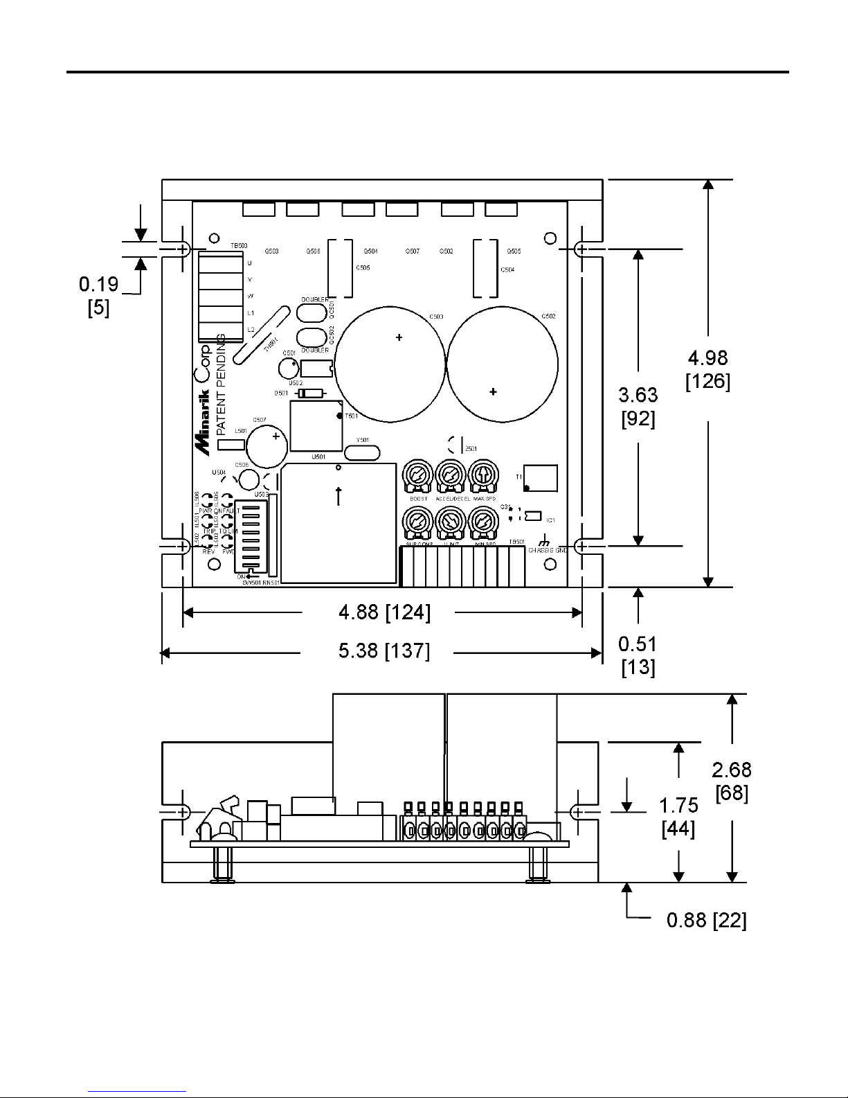
2
Figure 1. Dimensions
Dimensions
ALL DIMENSIONS IN INCHES [MILLIMETERS]
Page 15

3
Installation
Warning
Do not install, remove, or rewire this equipemnt with power
applied. Failure to heed this warning may result in fire,
explosion, or serious injury.
The chassis must be earth grounded. Use a star washer
beneath the head of at least one of the mounting screws to
penetrate the anodized chassis surface and to reach bare
metal.
•
Drive components are sensitive to electrostatic fields. Avoid
direct contact with the circuit board. Hold drive by the chassis
only.
•
Protect the drive from dirt, moisture, and accidental contact.
Provide sufficient room for access to the terminal block and
calibration trimpots.
•
Mount the drive away from heat sources. Operate the drive
within the specified ambient operating temperature range.
• Prevent loose connections by avoiding excessive vibration of
the drive.
Mounting
Page 16

4
Installation
Warning
Do not install, remove, or rewire this equipment with power
applied. Failure to heed this warning may result in fire,
explosion, or serious injury.
Circuit potentials are at 120 or 240 VAC above ground. To
prevent the risk of injury or fatality, avoid direct contact with
the printed circuit board or with circuit elements.
Do not disconnect any of the motor leads from the drive
unless power is removed or the drive is disabled. Opening
any one motor lead may destroy the drive.
•
Mount drive with its board in either a horizontal or vertical
plane. Six 0.19 in. (5 mm) wide slots in the chassis accept #8
pan head screws. Fasten either the large base or the narrow
flange of the chassis to the subplate.
•
Use 18-24 AWG wire for speed adjust potentiometer wiring.
Use 14–16 AWG wire for AC line (L1, L2) and motor (A1 and
A2) wiring.
Wiring
Page 17

5Installation
Warning
Under no circumstances should power and logic leads be
bundled together. Induced voltage can cause unpredictable
behavior in any electronic device, including motor controls.
As a general rule, Minarik recommends shielding of all
conductors.
If it is not practical to shield power conductors, Minarik
recommends shielding all logic-level leads. If shielding logic
leads is not practical, the user should twist all logic leads with
themselves to minimize induced noise.
It may be necessary to earth ground the shielded cable. If noise is
produced by devices other than the drive, ground the shield at the
drive end. If noise is generated by a device on the drive, ground
the shield at the end away from the drive. Do not ground both
ends of the shield.
If the drive continues to pick up noise after grounding the shield,
it may be necessary to add AC line filtering devices, or to mount
the drive in a less noisy environment.
Shielding guidelines
Page 18

6
Installation
Isolation (-PCM drives only)
The reference circuit (S1, S2 and S3) is optically isolated from
the rest of the drive electronics via HCPL7840. It will accept
either a grounded or isolated signal reference.
All drive inputs (inhibit, enable, brake and direction) are also
optically isolated from the rest of the drive electronics via
HCPL0453. It will accept a grounded or isolated bit-type open
collector (or switch) input.
Fusing
MAC series drives require external AC power line fuses.
Connect the external line fuse(s) in series with the AC voltage
input (see Figure 4, page 10). Use fast-acting fuses rated for 250
VAC or higher.
Heat sinking
MAC08-series drives require an additional heat sink (Minarik®
part number 223-0269) when the continuous phase current is
above 5 amps. All other MAC series drives have sufficient heat
sinking in their basic configuration. Use a thermally conductive
heat sink compound (such as Dow Corning® 340 Heat Sink
Compound) between the drive chassis and heat sink surface for
optimum heat transfer.
Page 19
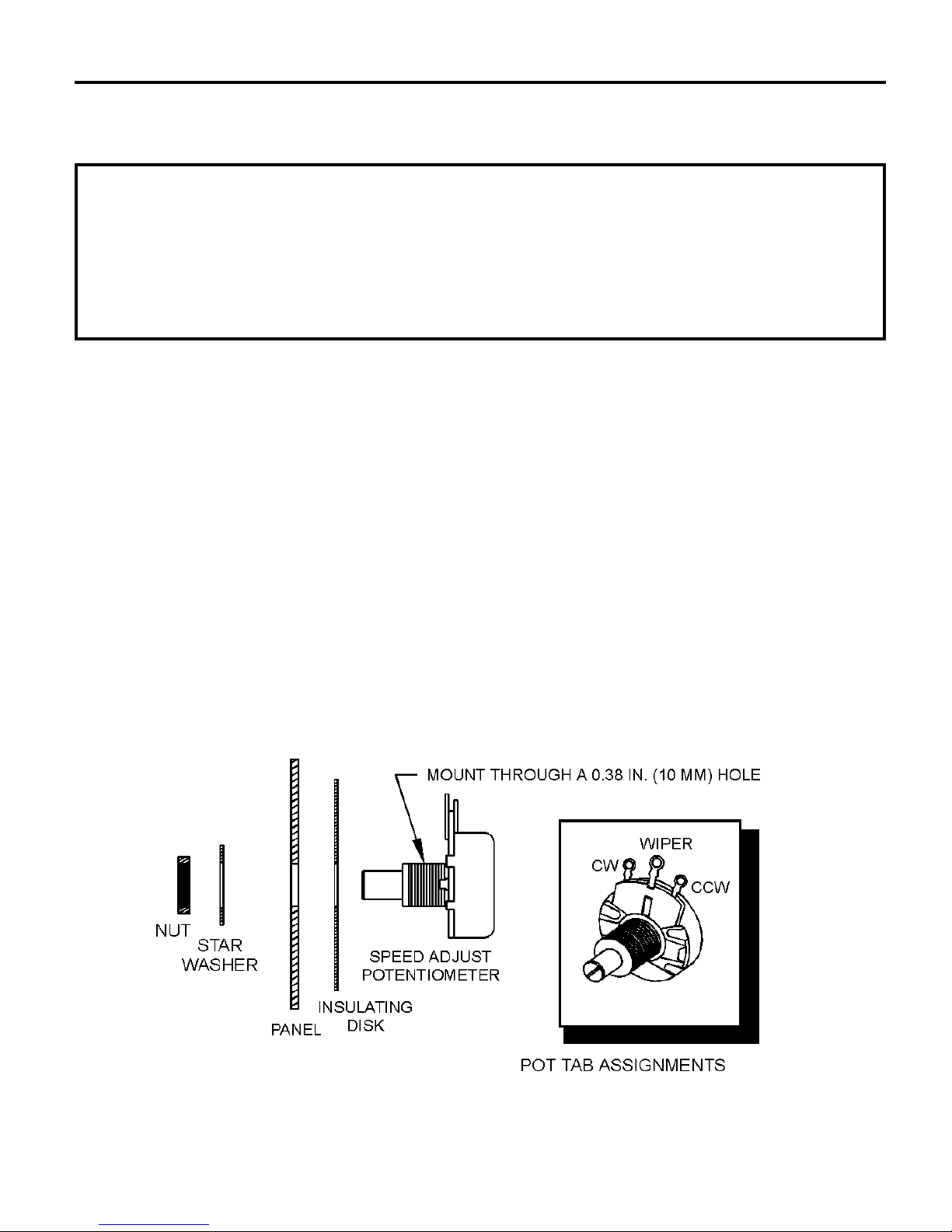
Mount the speed adjust potentiometer through a 0.38 in. (10 mm)
hole with the hardware provided (Figure 2). Install the circular
insulating disk between the panel and the 10K ohm speed adjust
potentiometer.
Twist the speed adjust potentiometer wire to avoid picking up
unwanted electrical noise. If speed adjust potentiometer wires are
longer than 18 in. (457 mm), use shielded cable. Keep speed
adjust potentiometer wires (S1, S2, S3)separate from power leads
(L1, L2, U, V, W).
7
Installation
Warning
Be sure that the potentiometer tabs do not make contact with
the enclosure. Grounding the input will cause damage to the
drive.
Speed adjust potentiometer
Figure 2. Speed Adjust Potentiometer
Page 20
8 Installation
Cage-clamp terminals
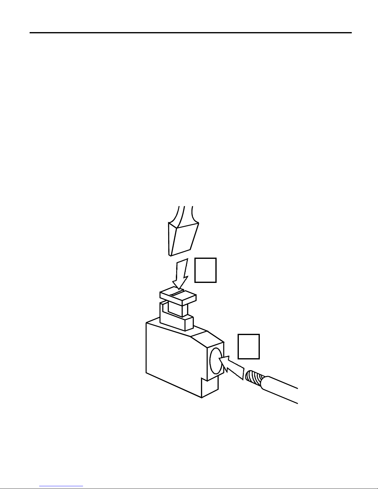
MAC Series drive connections include cage-clamp terminals (see
Figure 3). To insert a wire into a terminal:
1. Press down on the lever arm using a small screwdriver.
2. Insert wire into the wire clamp.
3. Release the lever arm to clamp wire.
Figure 3. Cage-Clamp Terminal
1
2
Page 21

Connections
9Installation
Warning
Do not install, remove, or rewire this equipemnt with power
applied. Failure to heed this warning may result in fire,
explosion, or serious injury.
Minarik strongly recommends the installation of a
master power switch in the voltage input line, as
shown in Figure 4 (page 10). The switch contacts
should be rated at a minimum of 200% of drive current
and 250 volts.
Connect the drive’s power and line fuse(s) to terminal board
TB503 as shown in Figure 4, page 10. Connect the drive’s signal
inputs and optional switches to terminal board TB501 as shown in
Figure 5, page 12. For voltage signal follower connections, refer
to Figure 22, page 45.
Connect the motor as shown in Figure 6 or 7, depending on the
type of motor being used. Refer to Figure 6 (page 14) for singlephase motor installation. Refer to Figure 7 (page 16) for threephase motor installation.
Page 22
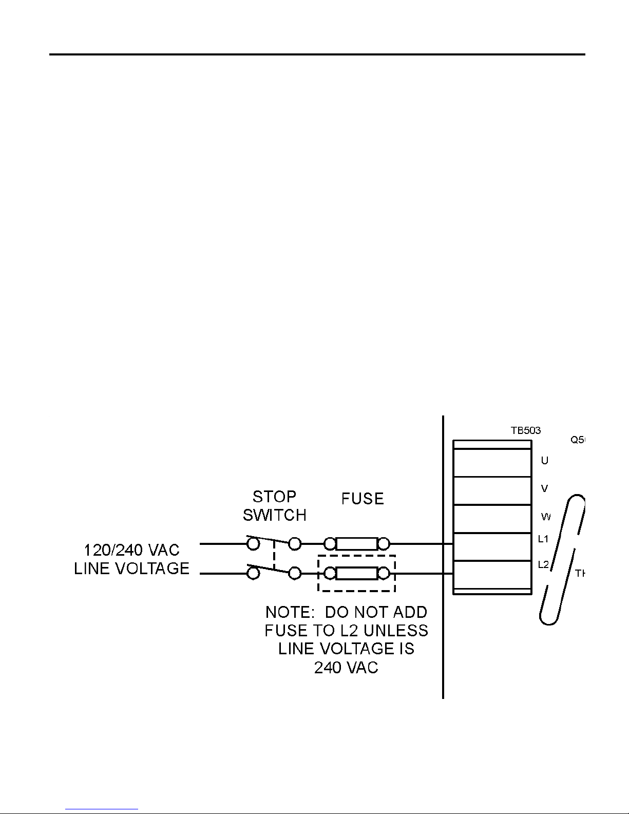
Power and fuse connections
1. Connect the input power leads to TB503 terminals L1 and L2.
2. Install a line fuse on L1 as shown. Do not install a line fuse
on L2 unless the input voltage is 240 VAC.
3.
Minarik strongly recommends the installation of a
master power switch in the voltage input line, as shown
in Figure 4. The switch contacts should be rated at a
minimum of 200% of drive current and 250 volts.
10 Installation
Figure 4. Power and Fuse Connections
Page 23

11Installation
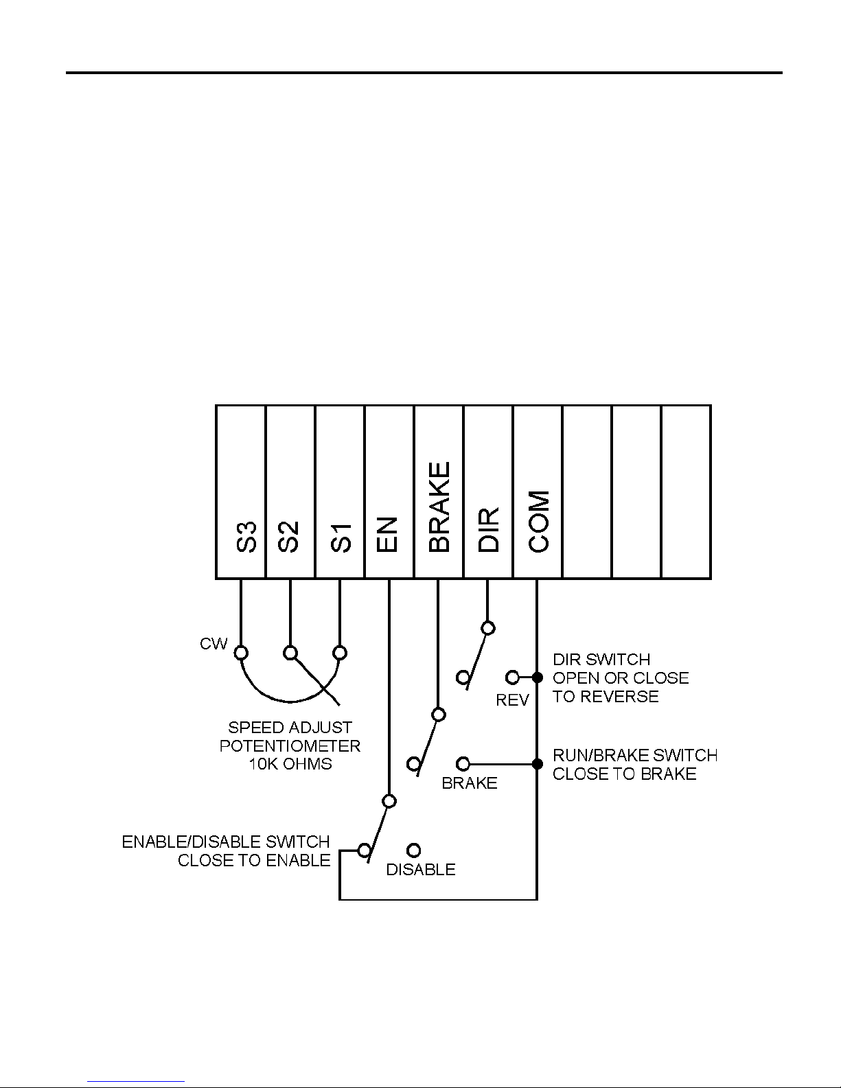
1. Connect a speed adjust potentiometer to terminals S1, S2 and
S3 on terminal board TB503 (see Figure 5, page 12). Make
sure the potentiometer is connected so that the motor speed
will increase as the wiper (S2) is turned clockwise (CW).
2. Connect a single-pole, single-throw ENABLE/DISABLE
switch between the EN and COM terminals as shown in
Figure 5.
3. Connect a single-pole, single-throw RUN/BRAKE switch
between the BRK and COM terminals as shown in Figure 5.
Closing the switch will cause the drive to regeneratively brake
to a stop.
4. Connect a single-pole, single-throw FWD/REV switch
between the DIR and COM terminals as shown
in Figure 5.
Opening or closing the switch will cause the drive to
change the direction of motor shaft rotation.
Warning
Allowing the RUN/BRAKE switch to remain in the BRAKE
position for an extended period of time may cause motor
overheating. Minarik recommends that you disable the
drive (as shown in Figure 10, page 27) or remove power if
the motor is to remain idle. Disable the drive or remove
power after the motor has come to a stop.
Signal and optional switch connections
Page 24
12 Installation
The drive will brake the motor before reversing, so there is no
need to wait for the motor to coast to a stop before changing
direction. The amber FWD or REV LED will blink as the drive
decelerates the motor but before it has changed direction.
Figure 5. Signal and Optional Switch Connections
TB501
Page 25

13Installation
Motor connections
Single-phase motors
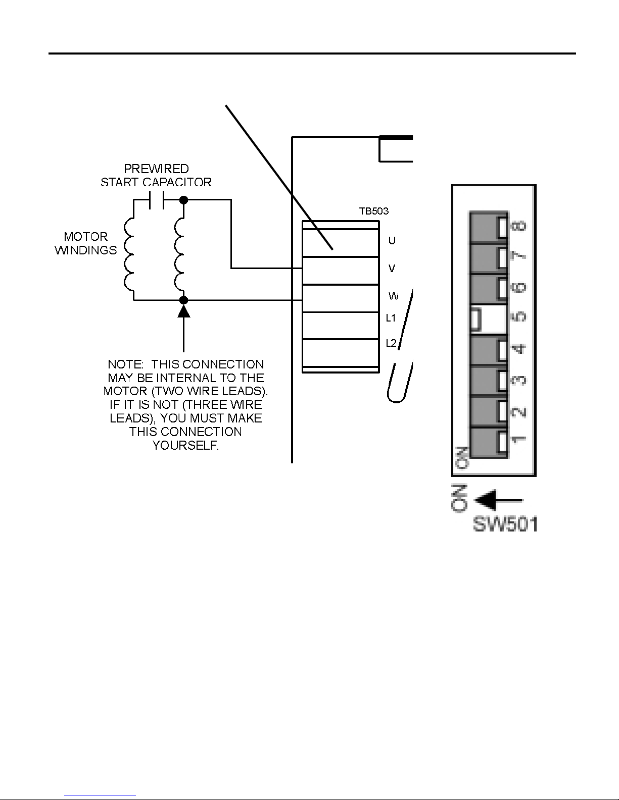
Ensure that DIP switch 5 on SW501 is set to ON for singlephase motor operation.
It is very important that terminal U be left open (no
connection) for single-phase operation.
If the motor and capacitor are sold separately, Minarik highly
recommends buying only the motor and operating in 2-phase
mode. The resulting speed range will be considerably wider,
while starting torque will approach that of a 3-phase motor.
Connect the motor as shown in Figure 6 (page 14). Ensure that
the prewired capacitor and its associated motor coil are connected
to terminals V and W as shown. This connection may be internal
if using a 2-wire motor. If the motor has three leads, you must
make this connection yourself.
If the motor capacitor is permanently mounted to the motor by the
factory, Minarik recommends leaving the capacitor attached
(thereby reducing the potential for human error) and running the
drive and motor in single-phase mode.
Page 26
14 Installation
Figure 6. Motor Connections for Single-Phase Operation
(Motor With Pre-Wired Capacitor)
DIP SWITCH
5=ON
NOTE: MAKE NO
CONNECTION TO
TERMINAL “U”
Page 27

Three-phase motors
15Installation
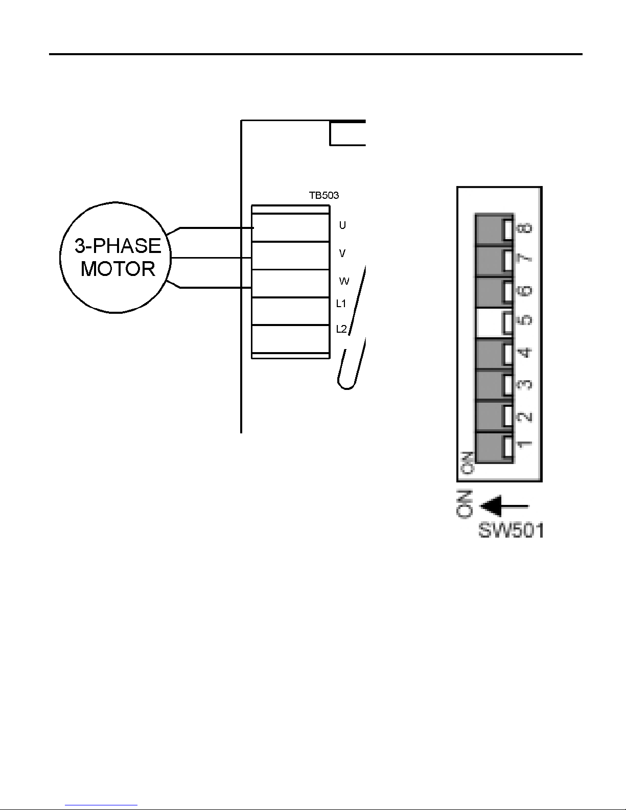
NOTE: Ensure that DIP switch 5 on SW501 is set to OFF for
three-phase motor operation.
MOTOR
PHASE
1OR2
3
DIP SWITCH
#5 SETTING
ON
OFF
Table 1. Motor Phase DIP Switch Settings
Connect a three-phase motor to terminals U, V and W as shown
in Figure 7 (page 16).
Page 28
16 Installation
Figure 7. Motor Connections for Three-Phase Motors
DIP SWITCH
5 = OFF
Page 29

17
Warning
Dangerous voltages exist on the drive when it is powered,
and up to 30 seconds after power is removed and the motor
stops. BE ALERT. High voltages can cause serious or fatal
injury.
Do not use the voltage-doubling feature when line voltage is
greater than 120 VAC. This will result in severe damage to
the motor and drive, possible explosion and severe injury.
Do not remove or install the voltage doubler jumper with
line voltage applied.
Operation
Page 30

MAC-series drives are equipped with a unique voltage-doubling
feature, for use when 240 VAC input voltage is not available.
This feature increases the 120 VAC MAC drives’ output from 120
VAC to 240 VAC, for use with 230V motors. The drive current
output remains the same.
18
Operation
Voltage doubler
Warning
Do not use the voltage-doubling feature when line voltage is
greater than 120 VAC. This will result in severe damage to
the motor and drive, possible explosion and severe injury.
Warning
Do not remove or install voltage doubler jumper with line
voltage applied. Do not apply line voltage greater than 120
VAC.
Jumper wire, if used, must be 14 AWG (1.63 mm) or greater.
Minarik highly recommends using the jumper included with
the MAC drive.
Page 31
To enable voltage doubling:
1. Verify that the line voltage source is 120 VAC. Do not apply
power at this time.
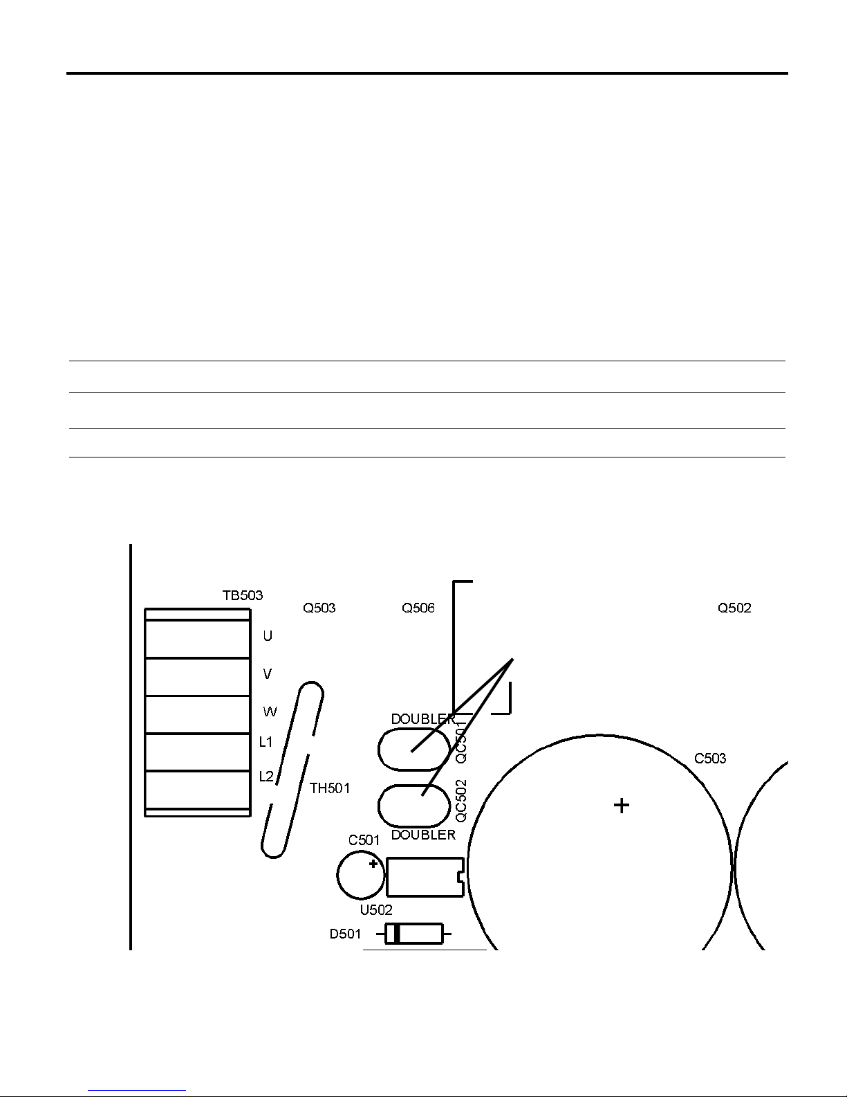
2. Add a jumper to the voltage doubling terminals. Refer to
Figure 8 for terminal location.
Table 2. Voltage Doubler Configuration
Jumper Setting Input Voltage Output Voltage
OFF 120/240 VAC 120/240 VAC
ON 120 VAC 240 VAC
19Operation
Figure 8. Voltage Doubler Terminals
VOLTAGE
DOUBLER
TERMINALS
Page 32

20
Operation
Before applying power
1. Verify that no conductive material is present on the PCB.
2. Verify that the voltage output is properly set by installing or
removing a jumper on the voltage doubler terminals, as
required. Refer to Figure 8 (page 19).
3. Verify that the correct voltage is connected to the inputs before
applying power. Ensure that 120 VAC ONLY is applied if the
doubler circuits are jumpered.
4. Verify that all DIP switches are correctly set for the motor
under load.
5. Set the speed adjust potentiometer to zero (full CCW). If a
voltage input signal is used, set the input signal to zero.
6. Set the FWD-REV switch (if installed) to the desired
direction. If no switch is installed, install or remove a jumper
across the DIR and COM terminals, as required.
7. Set the ENABLE/DISABLE switch (if installed) to ENABLE.
If no switch is installed short the EN and COM terminals on
TB501.
8. Set the RUN/BRK switch (if installed) to RUN, or remove the
jumper between the BRK and COM terminals on TB501.
Page 33

21Operation
NOTE: When power is applied, a one-second delay will
occur before motor operation.
Startup
1. Apply 120 or 240 VAC, 50/60 Hz, single-phase power to the
drive. The green POWER LED will come on. If it does not,
check the external line fuses to ensure that they are properly
installed and not blown. The amber FWD or REV LED will
light, indicating the direction of motor shaft rotation.
2. Gradually turn the speed adjust potentiometer clockwise to the
desired setting. If a voltage input signal is used, slowly
increase the signal to the desired level. The motor shaft will
rotate at a speed which is proportional to the input signal or
potentiometer wiper position.
3. If you attempt to start and the red TQ LIMIT LED comes on,
the control has entered torque limit mode. To avoid this
occurrence, you may:
a. increase the current limit setting (up to a maximum of
150% of the motor nameplate current rating);
b.lengthen the acceleration time enough to accommodate
the needed starting torque by adjusting the
ACCEL/DECEL trimpot; or
c. increase the accel torque power boost by setting the
BOOST trimpot DIP switches.
Page 34

To reverse motor direction:
When the motor is running in the forward direction, the amber
FWD LED will light; when the motor is running in reverse, the
amber REV LED will come on. To reverse the direction of motor
shaft rotation while the motor is running, set the FWD/REV
switch to the opposite position. If no FWD/REV switch is
installed, open or short the DIR and COM terminals on TB501, as
required. The amber LED showing the newly selected direction
will light the instant the motor changes direction.
When a new direction is selected, there is no need to close the
BRAKE input or open the ENABLE input. The control will
automatically decelerate the motor down to zero speed and then
reverse direction, accelerating and decelerating at a rate controlled
by the ACCEL/DECEL trimpot setting. The amber LED showing
the direction of rotation will blink while decelerating until the
motor shaft changes direction.
22
Operation
Page 35

23
To brake the motor, close the RUN/BRAKE switch, or place a
jumper across the BRK and COM teminals of TB501. See
Figure 5, page 12, for switch installation.
To coast the motor to a stop without disconnecting
power:
Starting and stopping methods
Braking
Operation
Warning
Allowing the RUN/BRAKE switch to remain in the BRAKE
position for an extended period of time may cause motor
overheating. Minarik recommends that you disable the
drive or remove power if the motor is to remain idle. See
Figure 5 (page 12) for ENABLE/DISABLE switch
installation.
Note: When the ENABLE input is closed, a one-second
delay will occur before power-up .
Open the ENABLE/DISABLE switch, or remove the jumper
between the EN and COM terminals of TB501. See Figure 5,
page 12, for switch installation.
Page 36

24
Line starting and line stopping (applying and removing AC
voltage input) is recommended for infrequent starting and
stopping of the drive only. It is also the recommended method for
emergency stopping of the drive. When AC voltage input is
applied to the drive, the motor accelerates to the speed set by the
speed adjust potentiometer. When AC voltage input is removed,
the motor coasts to a stop.
I²T trip operation (class 10 characteristics)
I²T trip level is based on the current limit setting. It protects the
drive from phase-to-phase short circuits, a mechanical jam, or
other potentially catastrophic conditions. If an overload or jam
occurs, the amber FWD or REV LED will go out and the red
CURRENT LED and TRIP LED will come on. After the
overload or jam has been corrected, open, then close the
ENABLE input to reset and restart the drive.
Line starting and line stopping
Operation
Warning
Minarik strongly recommends the installation of a
master power switch in the voltage input line (see
Figure 4, page 10). The switch contacts should be rated
at a minimum of 200% of drive current and 250 volts.
Page 37
25Operation
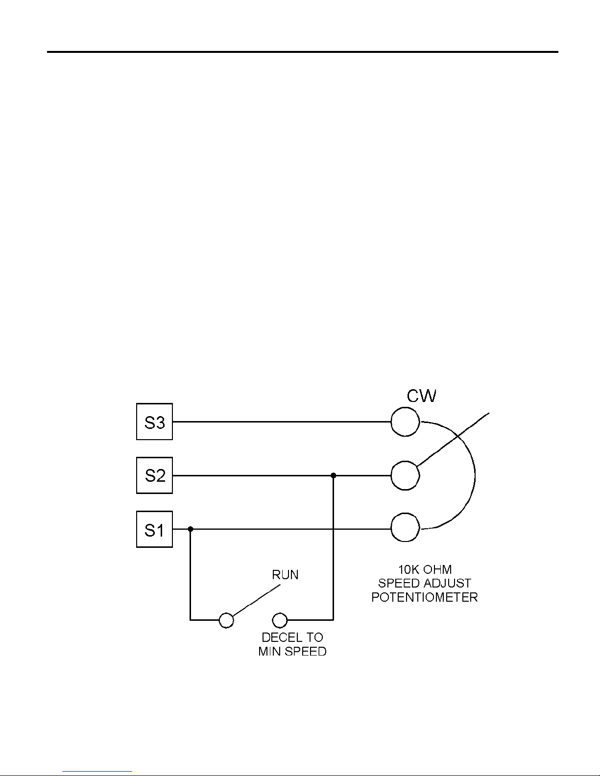
Decelerate to minimum speed
The circuit shown in Figure 9 may be used to decelerate a motor
to a minimum speed. Closing the switch between S2 and S1
decelerates the motor from set speed to a minimum speed
determined by the MIN SPD trimpot setting. If the MIN SPD
trimpot is set full CCW, the motor decelerates to zero speed when
the switch between S2 and S1 is closed. Calibrate the ACCEL\
DECEL trimpot to control the acceleration and deceleration
ramp. Set the switch to the RUN position to accelerate the motor
to set speed.
Figure 9. Run/Decelerate to Minimum Speed Switch
Page 38

26
The MAC series is equipped with DC injection braking, for use
with high-inertia applications.
As a rule, DC motors do not convert AC ripple in the DC voltage
to mechanical energy; instead, it is dissipated as waste heat. AC
motors perform in the opposite fashion: any DC component of an
AC voltage is converted to mechanical energy and acts as drag on
an AC motor. Because DC voltage induces a “steady-state”
magnetic field through the motor windings, the poles of the
armature and rotor will tend to align themselves magnetically.
Thus, the motor will not only slow down, but stop completely if
the DC voltage is great enough.
Decelerate to minimum with DC injection braking
Operation
Warning
Allowing the RUN/BRAKE switch to remain in the BRAKE
position for an extended period of time may cause motor
overheating. Minarik recommends that you disable the
drive (as shown in Figure 10) or remove power if the motor
is to remain idle. Disable the drive or remove power after
the motor has come to a stop.
Page 39
27Operation
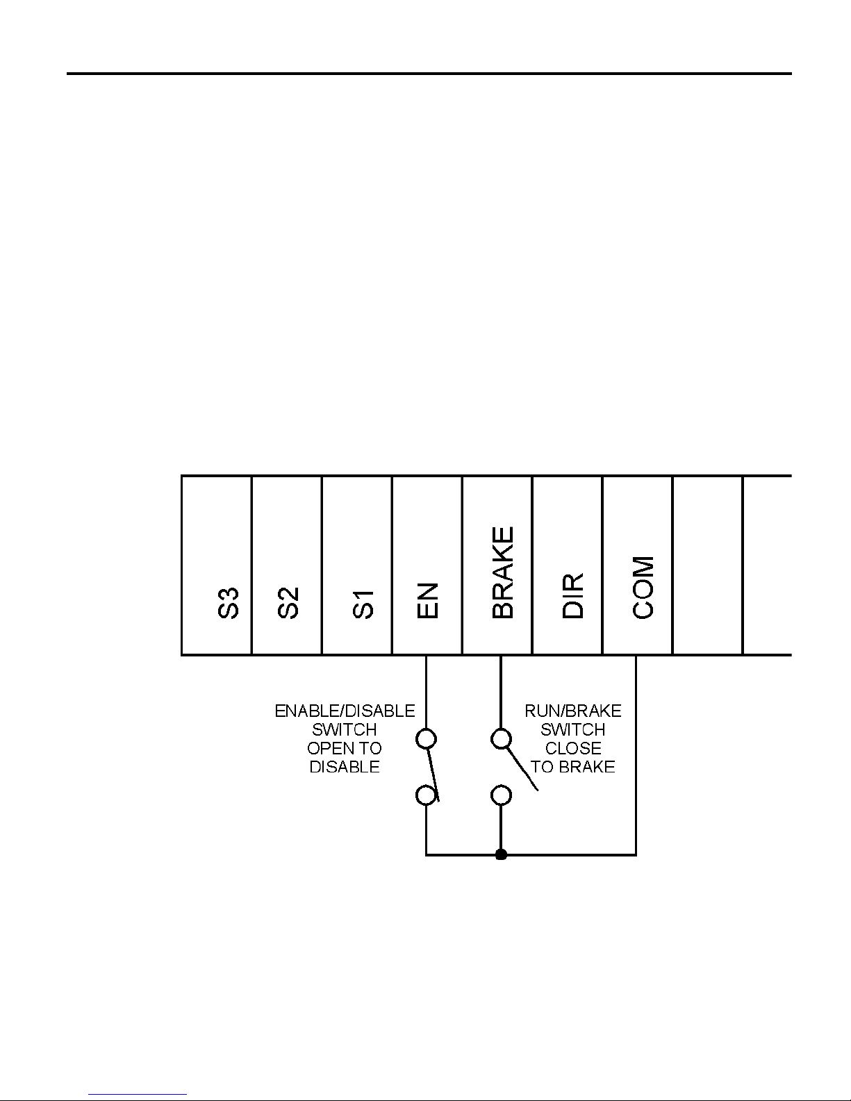
When injection braking is selected and the drive is disabled, the
normal AC phase output to the motor from the drive is set to its
minimum frequency. The drive simultaneously introduces a DC
voltage (not to exceed the threshold set by the CURRENT LIMIT
trimpot) into the motor stator. The motor will brake while the
signal is applied, then coast to a stop. This stops the motor much
more quickly and efficiently than simply coasting to a stop, while
avoiding high currents which may damage the motor and drive.
Figure 10. RUN-BRAKE switch
with optional ENABLE-DISABLE Switch
TB501
Page 40

28
Operation
Drive thermal protection
MAC series drives have built-in thermal protection. If the power
stage temperature reaches 100º C, the drive will turn off. The red
TRIP LED will then light to indicate a temperature overload
condition.
Thermal protection of the motor
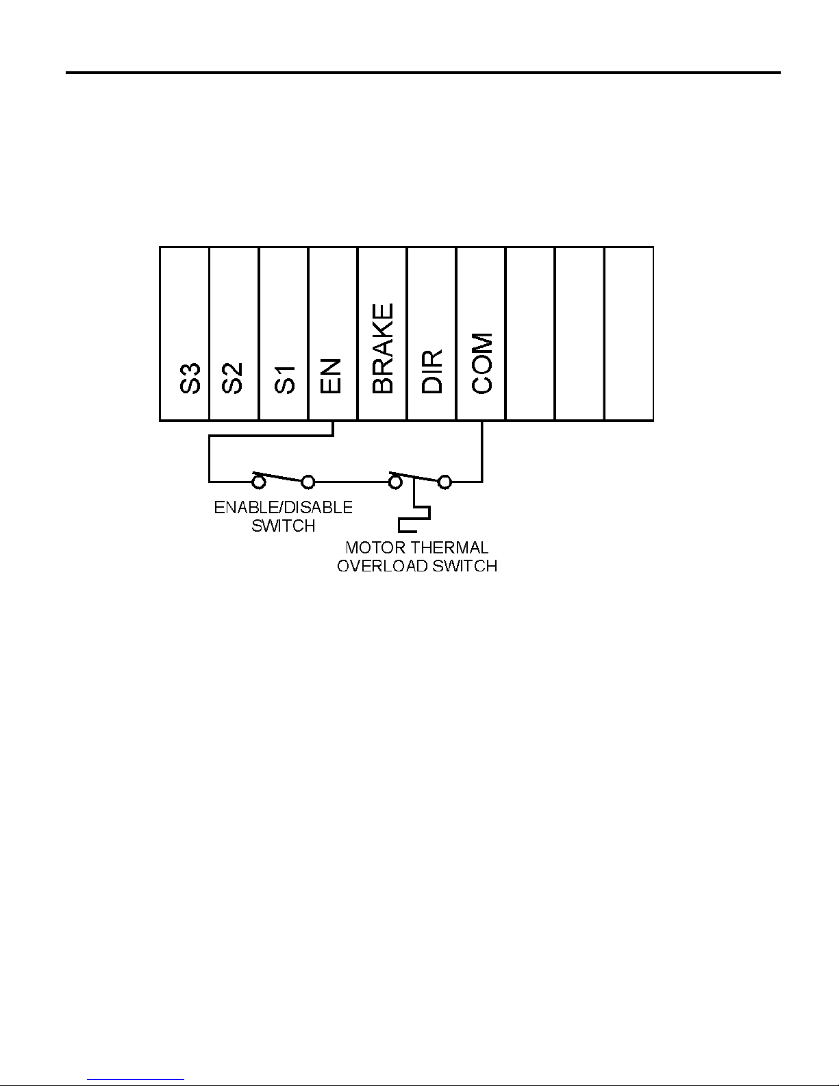
The enable input can also act as a motor thermal protection circuit
for motors having a built-in thermal protector. These thermal
protectors are operated only by motor heat and open the enable
circuit when the motor reaches a temperature which could cause
damage to the motor windings.
Normally, these thermal protectors automatically close the circuit
when the motor has cooled to a safe temperature. In operation,
when the drive is disabled, or when the motor overheats, the
thermal protector opens the circuit.
Page 41
29Operation
Figure 11. Thermal Overload Switch with
Optional Enable/Disable Switch
TB501
Page 42

30
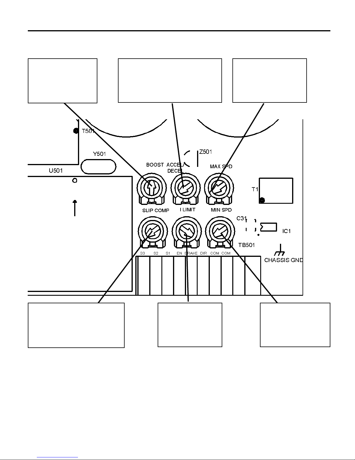
MAC Series drives have six user-adjustable trimpots. Each drive
is factory calibrated to its maximum horsepower rating. Readjust
the calibration trimpot settings to accommodate lower horsepower
motors. See Figure 12 for trimpot location.
All adjustments increase with CW rotation and decrease with
CCW rotation. Each trimpot is identified on the printed circuit
board.
Calibration
Warning
Dangerous voltages exist on the drive when it is powered,
and up to 30 seconds after power is removed and the motor
stops. When possible, disconnect the voltage input from the
drive adjusting the trimpots. If the trimpots must be adjusted
with power applied, use insulated tools and the appropriate
personal protection equipment. BE ALERT. High voltages
can cause serious or fatal injury.
Page 43
31Calibration
MAXIMUM
SPEED
MINIMUM
SPEED
CURRENT
LIMIT
ACCELERATION/
DECELERATION
SLIP
COMPENSATION
TORQUE
BOOST
Figure 12. Calibration Trimpot Layout
Page 44
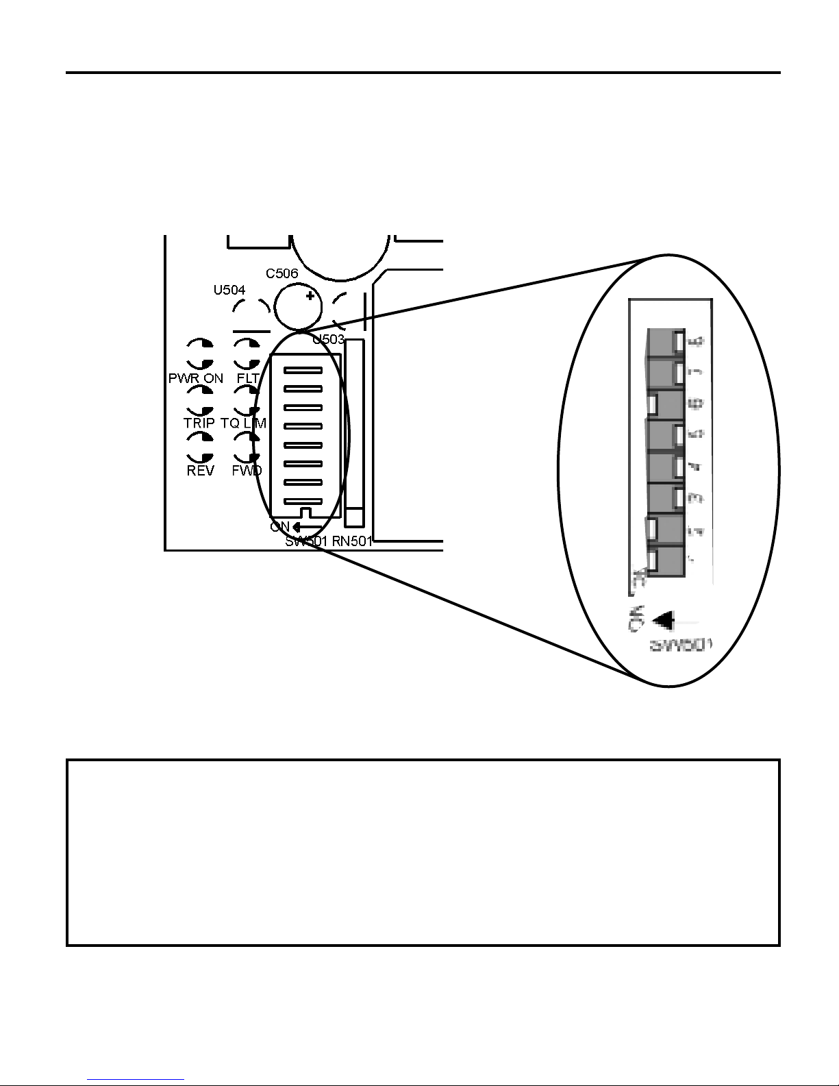
32 Calibration
NOTE: Whenever a DIP switch state is changed, it will be
ignored by the microprocessor until the drive is disabled,
then re-enabled.
NOTE: DIP switches are shown in their initial settings prior
to drive calibration.
Max Frequency DIP Switch Settings
Figure 13. DIP Switch Layout and Initial Settings
Page 45

33Calibration
1. Max frequency should match the motor’s nameplate
frequency. If you intend to overspeed the motor by
exceeding its nameplate rating, contact the motor
manufacturer to assure you do not exceed the motor’s
mechanical limits.
2. For this setting, the motor should be rated at 400 Hz.
3. Frequency at which nameplate base speed is achieved. This
is also the point at which the drive switches from constant
torque to constant horsepower.
4. If the base speed is extended, low-end torque will be
reduced so that the motor can achieve desired torque
through the entire speed range. Speed can only be extended
with a 208/230/230V motor.
Footnotes
† = Default (factory) setting.
MAX
FREQUENCY1(Hz)
60†
120
240
400
2
50
100
200
400
123
ON ON OFF
OFF ON OFF
ON OFF OFF
OFF OFF NA
ON ON ON
OFF ON ON
ON OFF ON
OFF OFF NA
6 BASE
3
6 BASE
4
ON 60 OFF 60
OFF 60 OFF 120
ON 60 OFF 240
OFF 400 NA 400
ON 50 ON 50
OFF 50 ON 100
ON 50 ON 200
OFF 400 NA 400
DIP SWITCH
SETTING
BASE SPEED DIP
SWITCH SETTING
Table 3. Max Frequency DIP Switch Settings (SW501)
Page 46

34 Calibration
NOTE: If you observe instability in the motor (motor seems
to run rough), refer to Troubleshooting (page 46).
MAC drives are shipped with a fundamental carrier frequency of
11 kHz (22 kHz with double-edge modulation). Although this
mode is very efficient, you may wish to switch to silent mode
(16 kHz or 32 kHz with double-edge modulation). To switch to
silent mode:
1. Disable the drive (or remove AC line power).
2. Set DIP switch 7 to ON (see Figure 14).
3. Enable the drive (or apply AC line power).
Calibration Procedure Setup for 60 Hz
Motors (See Figure 12):
1. Set all trimpots except I LIMIT and TQ BOOST full
counterclockwise (CCW).
2. Set the I LIMIT trimpot full CW.
3. Set the TQ BOOST trimpot to the 12 o’clock position.
4. Set DIP switches 1, 2, and 6 to ON; set DIP switches 3, 4, 5,
7 and 8 to OFF. See Figure 13 (page 32) for DIP switch
location.
5. Set the speed adjust pot or reference signal to zero speed.
Silent Mode
Page 47
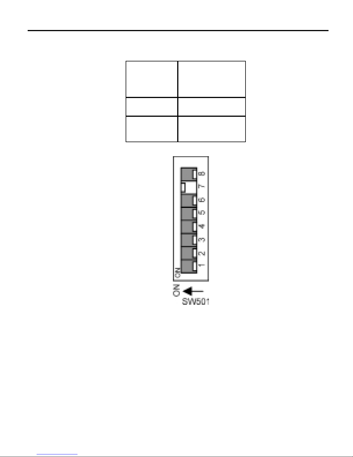
35Calibration
Figure 14. Carrier Frequency Mode DIP Switch Layout
SILENT MODE “ON”
Table 4. Carrier Frequency DIP Switch Settings
† Silent mode operates with a fundamental carrier frequency of
16/32 kHz. Normal mode operates with a fundamental carrier
frequency of 11/22 kHz.
†† Factory (default) setting.
MODE†
SILENT
NORMAL
DIP SWITCH
#7 SETTING
ON††
OFF
Page 48

36 Calibration
MINIMUM SPEED (MIN SPD)
Apply power to the drive. Slowly rotate the MIN SPD trimpot
CW until the motor begins to turn, then slowly rotate the pot
CCW until the motor just stops. This step calibrates the MIN
SPD pot to zero speed without hysteresis.
MAXIMUM SPEED (MAX SPD)
Rotate the speed adjust pot full CCW. Using a hand-held
tachometer or analog frequency meter as a reference, adjust the
MAX SPD trimpot until the desired speed or frequency is
reached.
CURRENT LIMIT (I LIMIT)
Warning
Do not exceed 115% of the motor nameplate rating. The
“modified” I²T algorithm in the microprocessor allows you
to reach 150% – and, under certain circumstances, 200%.
1. Ensure that motor speed is set to maximum.
2. Clip a clamp-on ammeter around one of the motor leads.
3. Load the motor shaft to 115% of the motor nameplate rating.
4. Rotate the I LIMIT trimpot CCW until the CURRENT LIMIT
LED (not the TRIP LED) lights. Then rotate the I LIMIT
trimpot CW until the LED just turns off.
5. Release the motor load (unlock the shaft).
Page 49

37Calibration
SLIP COMPENSATION (SLIP COMP)
Increase the motor speed to maximum. Slowly load the motor
until the AC phase current is at its maximum (100%). If the
motor slowed at all, rotate the SLIP COMP trimpot CW until the
motor shaft rotates at the original set speed.
ACCELERATION/DECELERATION (ACCEL/DECEL)
Quickly set the speed adjust pot to zero speed (full CCW) and
note the time the motor takes to stop. If the deceleration time
differs from the desired time, adjust the ACCEL/DECEL trimpot
until the desired time is reached. Rotating the ACCEL/DECEL
pot CW slows acceleration, thereby increasing the ramp time.
Rotating the ACCEL/DECEL pot full CCW does not allow the
motor to slow faster than it can coast. (To stop more quickly, you
may close the BRAKE input to inject DC into the motor.)
Set the speed adjust pot to zero (full CCW). Disable the drive by
opening the ENABLE/DISABLE switch or removing the jumper
from the EN and COM terminals.
Page 50

38 Calibration
The drive is now calibrated for optimum efficiency and
minimal motor heating.
Torque Boost Adjustment
OPTIONAL: To increase system efficiency, the torque boost
may be increased at this time. Torque boost should be set to zero
if the motor has no load or a slight load. If the drive trips, or the
TQ LIMIT LED flickers or illuminates during acceleration, you
must increase the torque boost setting. To increase torque boost,
perform the following:
1. Disable the drive.
2. Set DIP switch 4 to ON (Figure 15). This will set the accel
torque boost to 115%.
3. Enable the drive and rotate the speed adjust pot full CW
(maximum speed). If the motor accelerates quickly enough
and does not go into current limit, calibration is complete.
Page 51
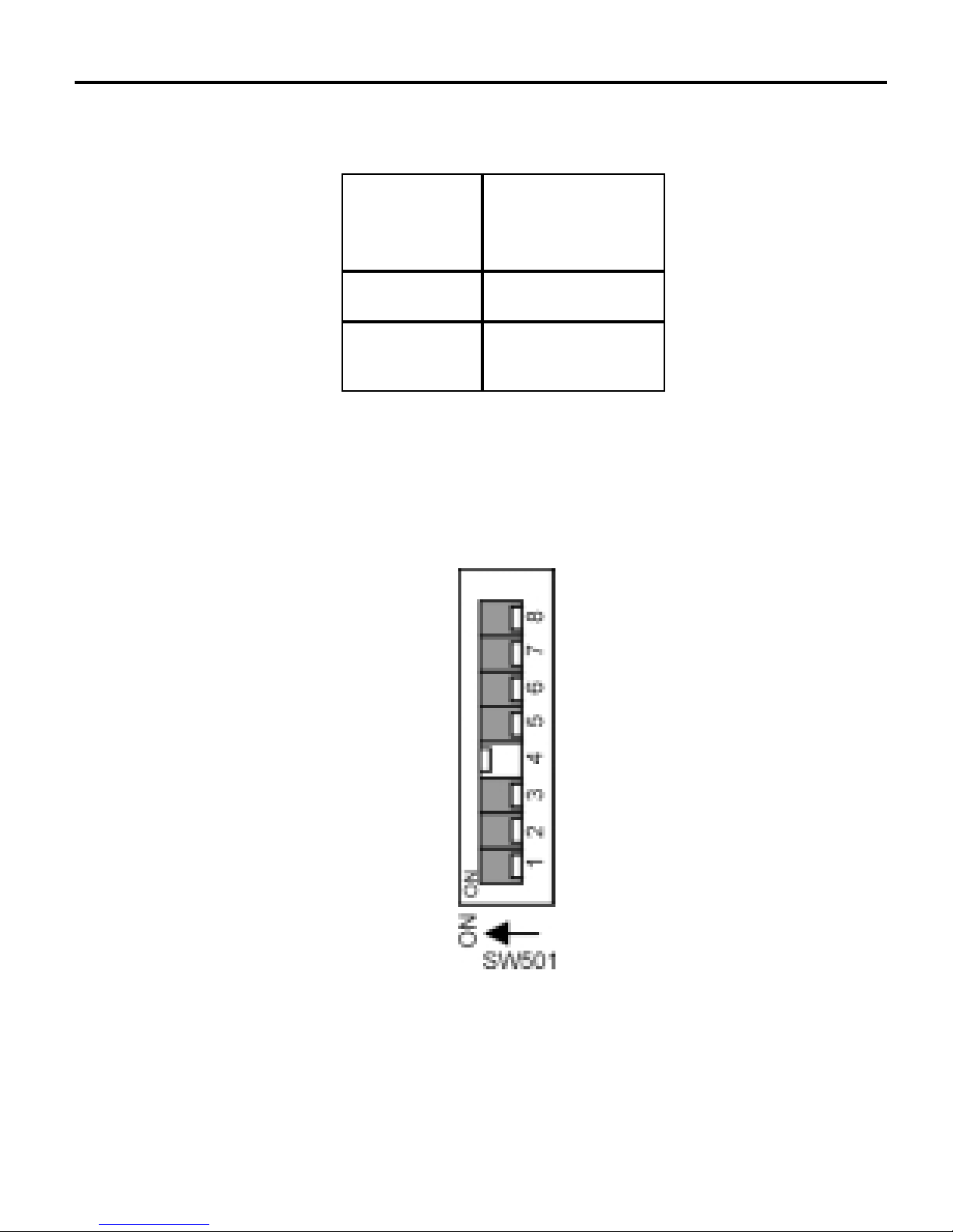
39Calibration
Figure 15. Torque Boost DIP Switch Setting
TORQUE BOOST
SET TO 115%
TORQUE
BOOST
115%
100%
DIP SWITCH
#4 SETTING
ON
OFF
Table 5. Torque Boost DIP Switch Settings
Page 52
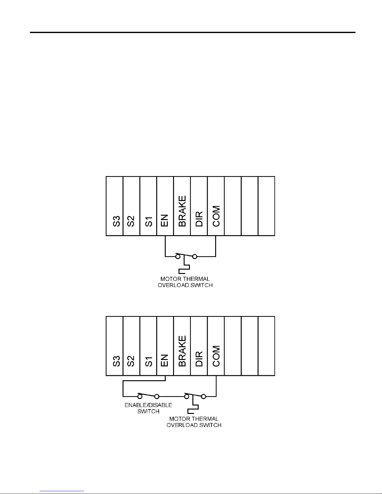
40
Figure 16. Thermal Overload Protection Switch Installation
Figure 17. Thermal Overload Protection Switch Installation
With Optional Enable/Disable Switch
Application Notes
Thermal Protection Switch Installation
To provide additional protection for the motor and drive, install a
thermal overload protection switch as shown in Figure 16. An
option is to install an ENABLE/DISABLE switch in series with
the thermal protection switch (Figure 17).
TB501
TB501
Page 53
41Application Notes
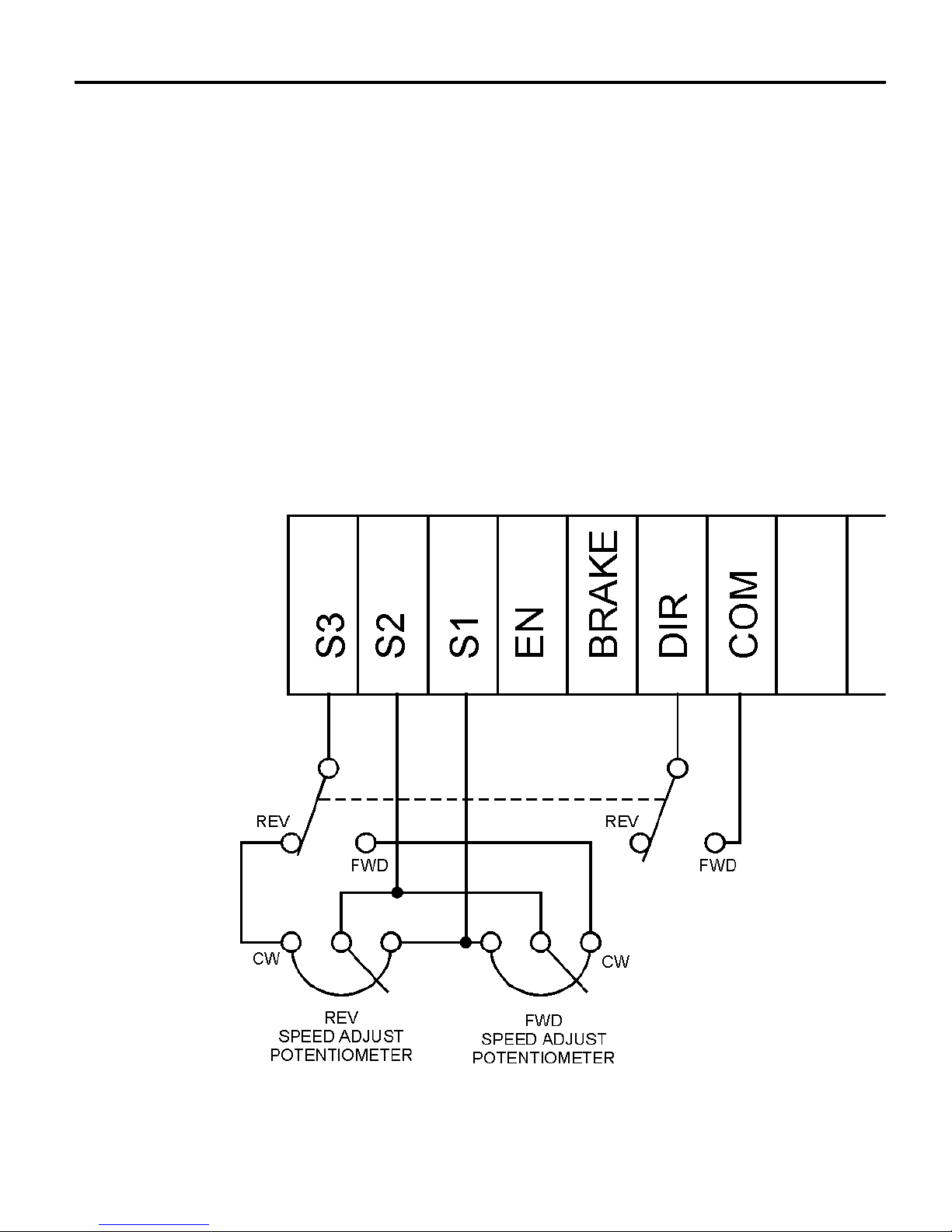
Independent adjustable speeds with
FWD-REV switch
Replace the speed adjust potentiometer with two single-pole
multi-position switches, and two or more potentiometers in
parallel, with a total parallel resistance of 10K ohms. Figure 18
shows the connection of two independent speed adjust
potentiometers that can be mounted at two separate operating
stations.
Figure 18. Independent Adjustable Speeds
TB501
Page 54
42
Application Notes
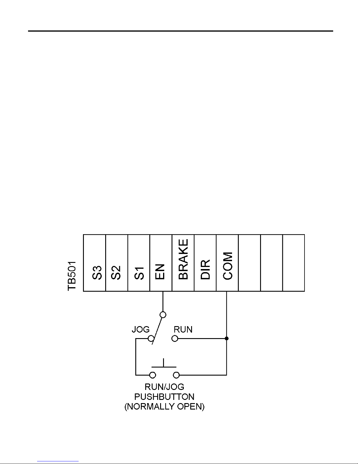
RUN/JOG switch
Using a RUN/JOG switch is recommended in applications where
quick stopping is not needed and frequent jogging is required.
Use a single-pole, two-position switch for the RUN/JOG switch,
and a single-pole, normally open, momentary operated pushbutton
for the JOG pushbutton.
Connect the RUN/JOG switch and JOG pushbutton to terminal
board TB501 as shown in Figure 19. The motor coasts to a stop
when the RUN/JOG switch is set to JOG. Press the JOG
pushbutton to jog the motor. Return the RUN/JOG switch to RUN
for normal operation.
Figure 19. RUN/JOG Switch
Page 55
43Application Notes
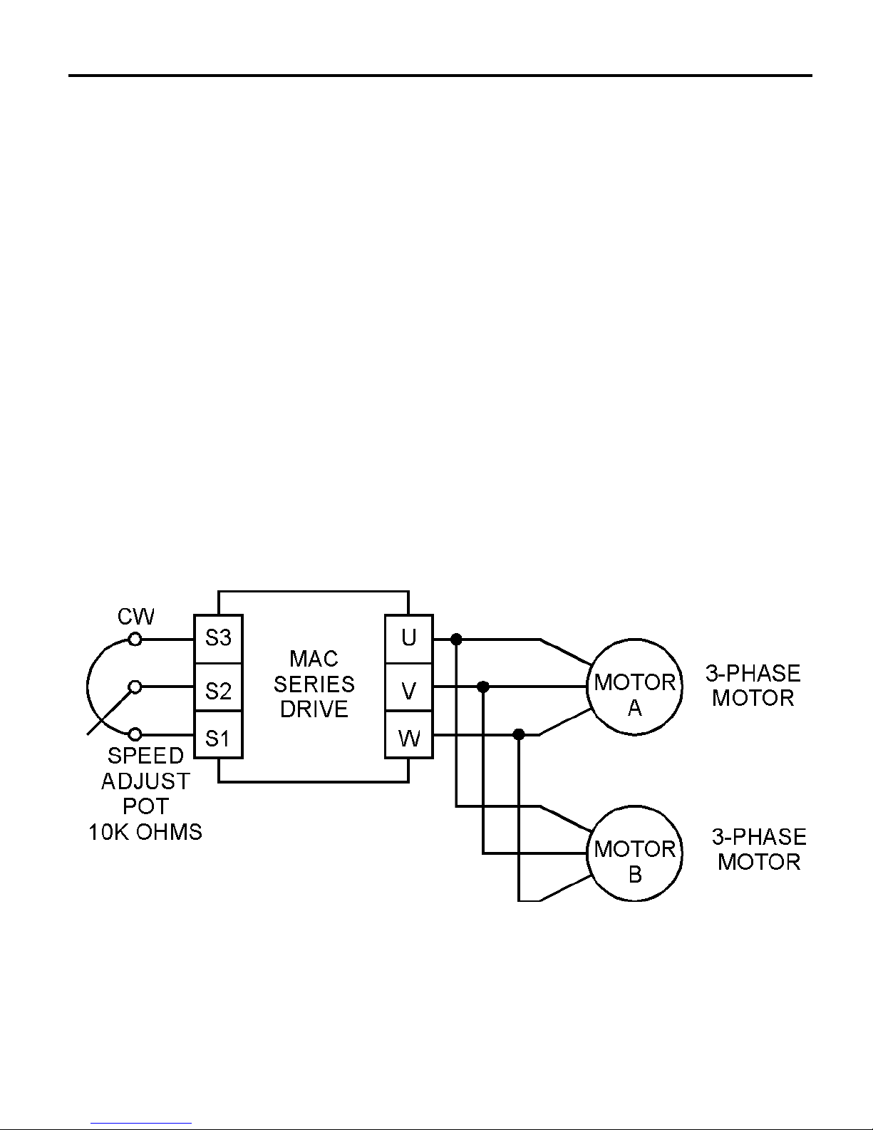
Figure 20. Single Speed Potentiometer
Control of Multiple Motors
Single speed potentiometer control of
multiple motors
The MAC series of controls is capable of operating up to eight 3phase motors simultaneously. All motors must be of the same
type and must control similar loads. Connect each motor as
shown in Figure 20 below.
Page 56
44
Application Notes
Reversing
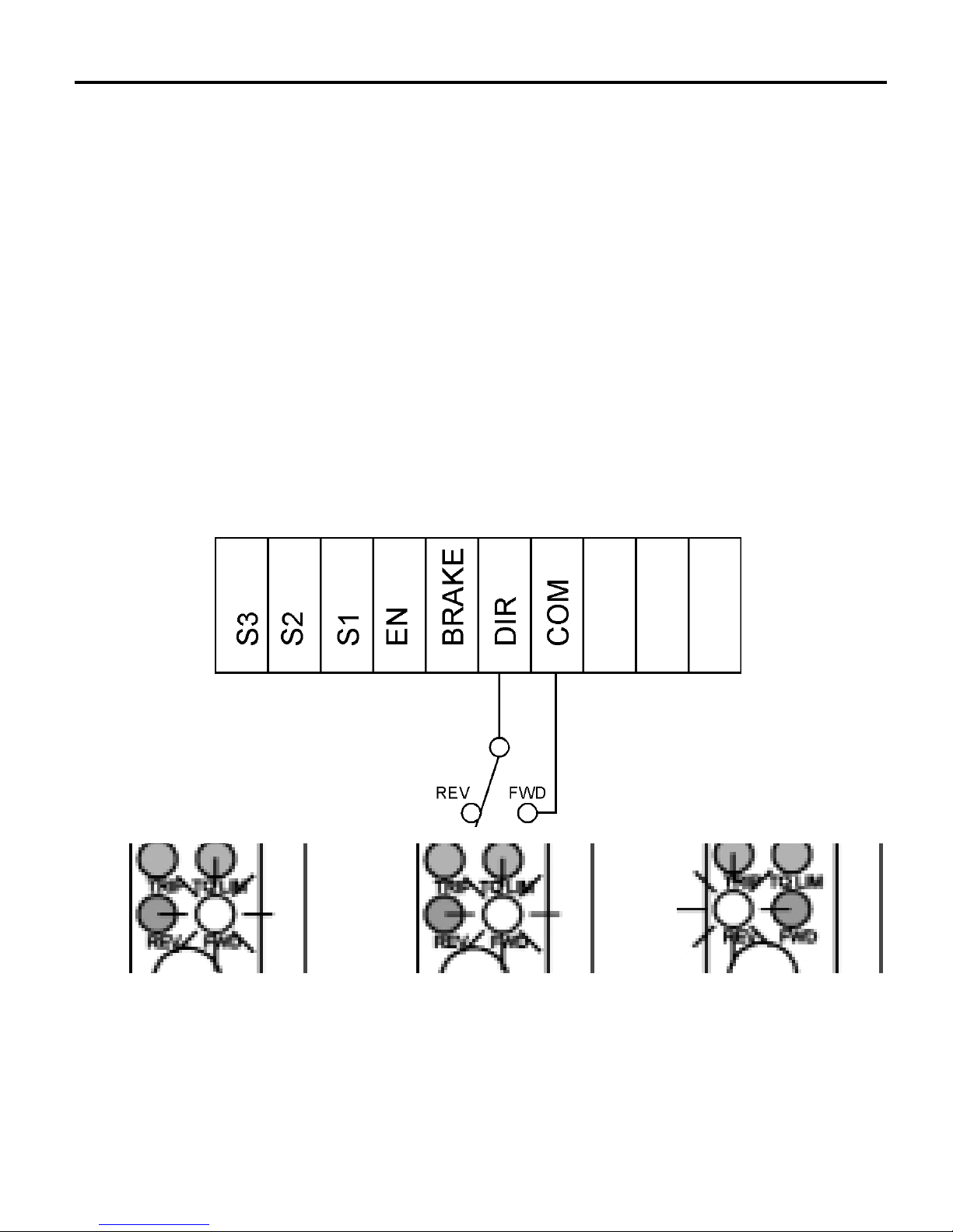
To reverse the direction of motor shaft rotation, remove or install
a jumper between the DIR and COM terminals of TB501, as
required. An option is to install a single-pole, two-position
switch as shown in Figure 21. The drive will brake the motor
before reversing, so there is no need to wait for the motor to coast
to a stop before changing direction. The amber FWD or REV
LED will blink as the drive decelerates the motor but before it has
changed direction.
Figure 21. Reversing Circuit Connection
In this example, the FWD
LED is lit when the motor
is running in the forward
direction...
...then blinks as the motor
decelerates before
changing direction...
...then the REV LED
lights as the motor
begins running in the
reverse direction.
TB501
Page 57
45Application Notes
Voltage follower
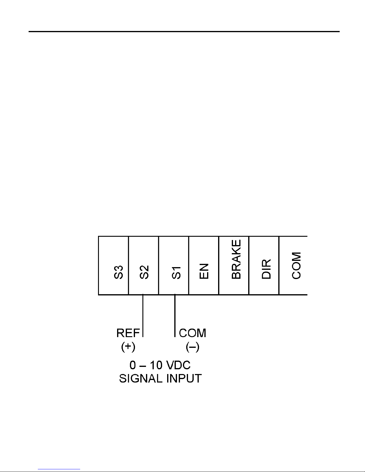
Instead of using a speed adjust potentiometer, the drive may be
wired to followa0to+10VDCisolated voltage signal (Figure
22). Connect the signal common (–) to S1. Connect the signal
high or (+) to S2. Make no connection to S3. A potentiometer can
be used to scale the analog input voltage.
NOTE: An isolated reference signal must be used with the nonPCM MACdrive. Do not use a grounded reference with any nonPCM MAC series drive.
Figure 22. Voltage Follower Connections
TB501
Page 58

46
Troubleshooting
Warning
Dangerous voltages exist on the drive when it is powered,
and up to 30 seconds after power is removed and the motor
stops. When possible, disconnect the voltage input from the
drive while troubleshooting. Be alert. High voltages can
cause serious or fatal injury.
Before troubleshooting
Perform the following steps before starting any procedure in this
section:
• Disconnect AC voltage input from the drive. Wait 30 seconds
for power to discharge. The green POWER LED will blink
while power is discharging.
• Check the drive closely for damaged components.
• Check that no wire chips or other foreign material has become
lodged on the printed circuit board.
• Verify that every connection is correct and in good
condition.
• Verify that there are no short circuits or grounded
connections.
• Check that the drive’s rated phase current and RMS voltage
are consistent with the motor ratings.
Page 59

47Troubleshooting
Diagnostic LEDs
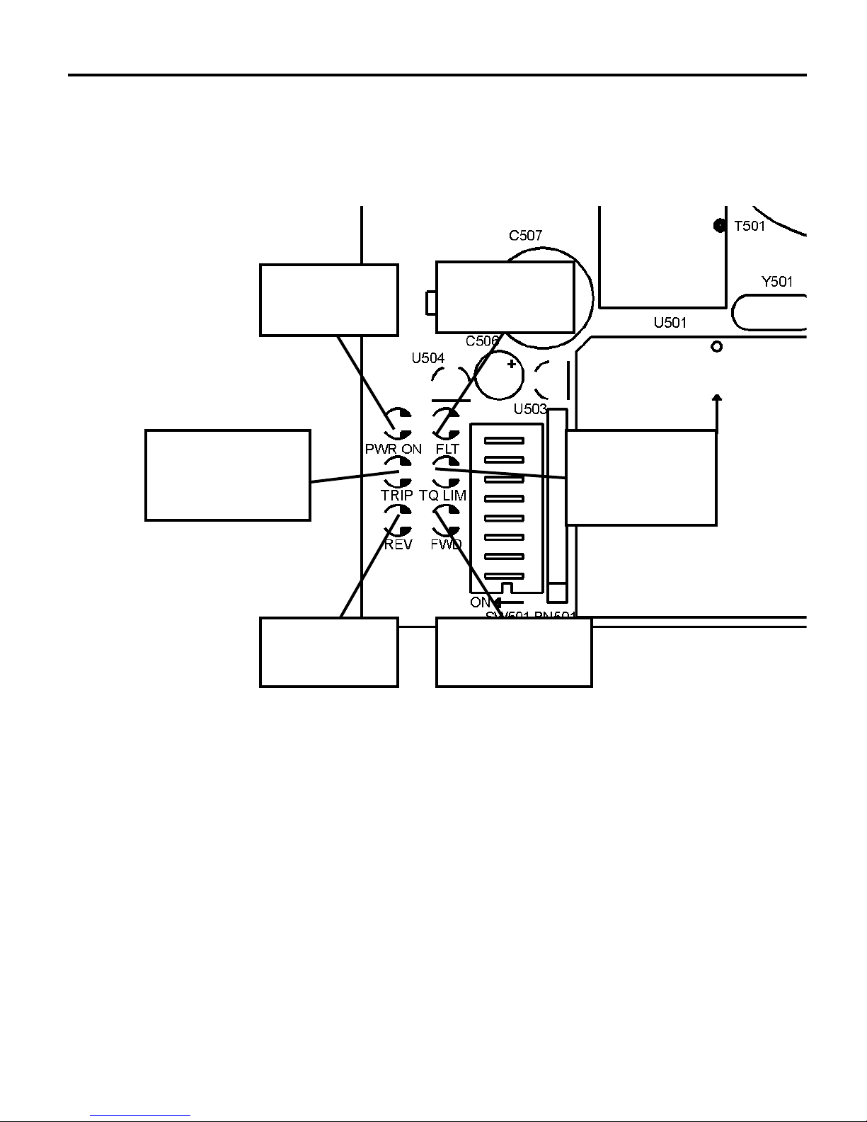
MAC-series drives contain six diagnostic LEDs (see Figure 23,
pg. 49):
POWER ON (green)
The green POWER ON LED lights when power is applied to the
drive.
FAULT (red)
The red FAULT LED lights in any of the following conditions:
1. Failure of the power stage or its components.
2. The monitor detects an overcurrent condition of more than
250% of the drive’s rating.
3. A short between any two of the three AC phases.
4. Loss of phase.
TRIP I²T (red)
The red TRIP LED lights when a thermal overload has occurred.
The TRIP and TQ LIM LEDs light at the same time if the motor
load exceeds 250% of the motor’s rated current or I²T class-10
conditions. If the TRIP and TQ LIM LEDs are lit at the same
time, the drive has gone into current overload.
Page 60

48
Troubleshooting
REV (amber)
The amber REV LED lights to show the motor is moving in the
reverse direction. The LED blinks when the direction input has
changed until the motor changes direction.
FWD (amber)
The amber FWD LED lights to show the motor is moving in the
forward direction. The LED blinks when the direction input has
changed until the motor changes direction.
TQ LIM (red)
The red TQ LIM (torque limit) LED will light at the same time as
the TRIP LED if the current required to move the load exceeds
the I LIMIT trimpot setting.
Page 61
49Troubleshooting
Figure 23. Diagnostic LED Layout
REVERSE FORWARD
TORQUE
LIMIT
POWER
FAULT
I²T TORQUE
TRIP
Page 62

50
Troubleshooting
LED fault indications
Green POWER LED does not light when power is
applied.
1. The input voltage may be too low. Check that the input
voltage is above 90 VAC.
2. Check that the external fuse(s) is/are not blown. Replace if
necessary.
3. Check the connections to the terminal block for loose, broken
or miswired leads.
Green POWER LED blinks after power is turned off.
1. Power has been removed from the drive and the power supply
is discharging.
Red TRIP LED is lit steadily (does not blink) at the
same time as the TQ LIM LED .
1. The motor load has exceeded the I²T class 10 current
characteristics. Check there is no phase-to-phase short.
2. If no short exists, check that there is no jammed load.
Page 63

51Troubleshooting
Red TRIP LED is lit steadily (does not blink); red TQ
LIM LED is not lit.
1. The drive has gone into thermal overload (drive temperature
has exceeded 100º C).
Red FAULT LED is lit.
1. The control has a power stage failure.
2. The motor load is more than 250% above current limit setting.
3. The motor has a phase-to-phase short circuit or possible loss
of phase.
Red TQ LIMIT LED is lit.
1. The I LIMIT trimpot is out of calibration and must be
adjusted. See Calibration for information on adjusting the
trimpot.
2. The motor load is greater than 115% of the torque limit
setting, but less than 250%.
3. Torque boost is set too high.
Amber REV LED blinks; FWD LED not lit.
The drive was running in the reverse direction when the direction
(DIR) input state was changed. The REV LED blinks until the
direction of motor shaft rotation is actually reversed.
Page 64

52
Troubleshooting
Amber FWD LED blinks; REV LED not lit.
The drive was running in the forward direction when the direction
(DIR) input state was changed. The FWD LED blinks until the
direction of motor shaft rotation is actually reversed.
Clearing LED fault indications
Reset all LED fault indications using the following procedure:
1. Disable the drive by opening the ENABLE input (remove the
jumper between the EN and COM terminals of TB501).
2. Re-install the jumper between the EN and COM terminals of
TB501 to close the ENABLE input and restart the drive.
To make this process easier, Minarik recommends installing a
single-pole, single-throw DISABLE/ENABLE switch between the
EN and COM terminals of terminal board TB501. See Signal and
Optional Switch Connections on page 12 for an illustration.
Page 65

Problem Possible
Cause
53
Suggested
Solution
Troubleshooting
1. Check that line fuses
are properly sized for the
motor being used.
2. Check motor cable and
motor for shorts.
3. Add a blower to cool
the drive components;
increase I LIMIT settings
(page 36).
1. Increase the speed
adjust potentiometer
setting or voltage input
signal.
2. Check connections
to input. Verify that
connections are not open.
3. Check diagnostic
LEDs for drive condition.
Remove motor load.
External line fuse
blows
External line fuse
does not blow, but
the motor does not
run
1. Line fuses are the
wrong size.
2. Motor or motor
cable is shorted to
ground.
3. Nuisance tripping
caused by a
combination of
ambient conditions
and high-current
spikes (i.e. reversing).
1. Speed adjust
potentiometer or
voltage input signal is
set to zero speed.
2. Speed adjust
potentiometer or
voltage input signal is
not properly connected
to drive input;
connections are open.
3. Drive is “tripped”
off or has gone into
thermal overload.
Page 66

ProblemPossible
Cause
Suggested
Solution
54
Troubleshooting
4. Drive has been
disabled.
5. Drive is in brake
mode.
6. Drive is in current
limit.
7. Drive is not
receiving AC voltage
input.
8. Motor is not
connected.
1. Switches are set
incorrectly.
2. MIN or MAX SPD
are not calibrated.
1. Base speed DIP
switches are
incorrectly set.
2. MAX SPD setting is
too low.
External line fuse
does not blow, but
the motor does not
run (cont.)
Motor runs too slow
or too fast at set
speed
Motor will not reach
the desired speed
4. Ensure that EN and
COM terminals are
properly connected.
5. Ensure that BRAKE
terminal is not shorted to
COM terminal.
6. Verify that motor is
not jammed. Increase I
LIMIT setting if it is set
too low.
7. Apply AC line voltage
to L1 and L2.
8. Connect motor to drive
outputs U, V and W.
1. Verify all switch
settings.
2. Calibrate MIN and
MAX SPD trimpots
(page 36).
1. Reset DIP switches.
2. Increase MAX SPD
setting (page 36).
Page 67

Problem Possible
Cause
Suggested
Solution
55Troubleshooting
Motor will not reach
the desired speed
(cont.)
Motor pulsates or
surges under load
3. BOOST and SLIP
COMP settings are too
low.
4. Nominal input
voltage may be too
low for motor
5. Motor is
overloaded.
1. SLIP COMP is set
too high.
2. Motor “bouncing”
in and out of torque
limit.
3. Possible instabilities
in silent mode (1 HP
motors only)
3. Recalibrate BOOST
and SLIP COMP settings
(pp 37-38).
4. Compare motor
voltage to input voltage;
replace motor if
necessary (see page 11)
5. Check motor load.
Resize the motor if
necessary.
1. Adjust the SLIP
COMP setting slightly
CCW until the motor
speed stabilizes (page
37).
2. Make sure motor is not
undersized for load;
adjust I LIMIT setting
CW (page 36).
3. Disable drive; set DIP
switch #7 to ON; reenable drive.
Page 68

ProblemPossible
Cause
Suggested
Solution
56 Troubleshooting
Motor does not
reverse
TQ is unsatisfactory
at high speeds.
1. Check FWD/REV
switch connection.
2. Check reversing circuit
by shorting FWD/REV
terminal to COM
terminal with jumper
wire.
1. Check I LIMIT
setting (page 36).
2. Check boost setting.
3. “Fix” load (i.e.,
straighten mounting,
coupling, etc.); or replace
motor and drive with
motor and drive rated for
higher horsepower.
4. Compare motor
voltage to input voltage.
Replace motor if
necessary (see page 10).
1. Bad FWD/REV
switch connection.
2. Reversing circuit
not working properly.
1. I LIMIT set too
low.
2. TQ BOOST set too
low.
3. Load may exceed
rating of motor/drive.
4. Nominal input
voltage may be too
low for motor.
Page 69

57
Problem Suggested
Solution
Troubleshooting
Drive goes into
current limit or I2T
trip on power-up
1. Motor is
undersized for load.
2. TQ BOOST set too
high.
3. Accel torque boost
is set to ON.
4. Leads from drive to
motor are too long, or
wire gauge is too
small.
1. Resize motor or use
proper drive for motor.
2. Reduce TQ BOOST
trimpot setting (page 38).
3. Set torque boost
SW501 DIP switch #4 to
OFF.
4. Shorten leads and/or
increase wire gauge.
Page 70

58
Troubleshooting
Replacement Parts
Replacement parts are available from Minarik Corporation and its
distributors for this drive series.
Table 6. Replacement Parts
Model No. Symbol Description Minarik®P/N
MAC05-D240AC C502-503 1000 uF, 200 VDC Capacitor 011-0096
Q502-Q507 IGBT 070-0085
TH501 20-amp Thermistor 033-0007
TB501 10-pin Terminal Block 160-0153
TB503 5-pin Terminal Block 160-0114
10K ohm Potentiometer Kit 202-0100
MAC05-D240AC-PCM Same parts as above
MAC08-D240AC Same parts as above, except:
C502-503 1500 uF, 250 VDC Capacitor 011-0089
TH501 30-amp Thermistor 033-0009
MAC08-D240AC-PCM Same parts as above
Potentiometer Kit Contains:
10K ohm, 5W Potentiometer
3/8-32 X 1/2 Nut
3/8 INT Tooth Lock Washer
Potentiometer Insulating Washer
Page 71

Unconditional Warranty
A. Warranty
Minarik Corporation (referred to as “the Corporation”) warrants that its products will be free from
defects in workmanship and material for twelve (12) months from date of manufacture thereof.
Within this warranty period, the Corporation will repair or replace such products that are returned
to Minarik Corporation, 901 East Thompson Avenue, Glendale, CA 91151-2011 USA.
This warranty shall not apply to any product that has been repaired by unauthorized persons.
The Corporation is not responsible for removal, installation, or any other incidental expenses
incurred in shipping the product to and from the repair point.
B. Disclaimer
The provisions of Paragraph A are the Corporation’s sole obligation and exclude all other
warranties of merchantability for use, express or implied. The Corporation further disclaims any
responsibility whatsoever to the customer or to any other person for injury to the person or
damage or loss of property of value caused by any product that has been subject to misuse,
negligence, or accident, or misapplied or modified by unauthorized persons or improperly
installed.
C. Limitations of Liability
In the event of any claim for breach of any of the Corporation’s obligations, whether express or
implied, and particularly of any other claim or breech of warranty contained in Paragraph A, or of
any other warranties, express or implied, or claim of liability that might, despite Paragraph B, be
decided against the Corporation by lawful authority, the Corporation shall under no
circumstances be liable for any consequential damages, losses, or expense arising in
connection with the use of, or inability to use, the Corporation’s product for any purpose
whatsoever.
An adjustment made under warranty does not void the warranty, nor does it imply an extension
of the original 12-month warranty period. Products serviced and/or parts replaced on a nocharge basis during the warranty period carry the unexpired portion of the original warranty only.
If for any reason any of the foregoing provisions shall be ineffective, the Corporation’s liability for
damages arising out of its manufacture or sale of equipment, or use thereof, whether such
liability is based on warranty, contract, negligence, strict liability in tort, or otherwise, shall not in
any event exceed the full purchase price of such equipment.
Any action against the Corporation based upon any liability or obligation arising hereunder or
under any law applicable to the sale of equipment or the use thereof, must be commenced
within one year after the cause of such action arises.
Page 72

901 E Thompson Avenue
Glendale, CA 91201-2011
Tel: (800) MINARIK (646-2745)
Fax: (800) 394-6334
www.minarikcorp.com
Document number 250-0275, Revision 2
Printed in the U.S.A – 01/01
North America $12.00, Outside North America $15.00
 Loading...