

Page 1
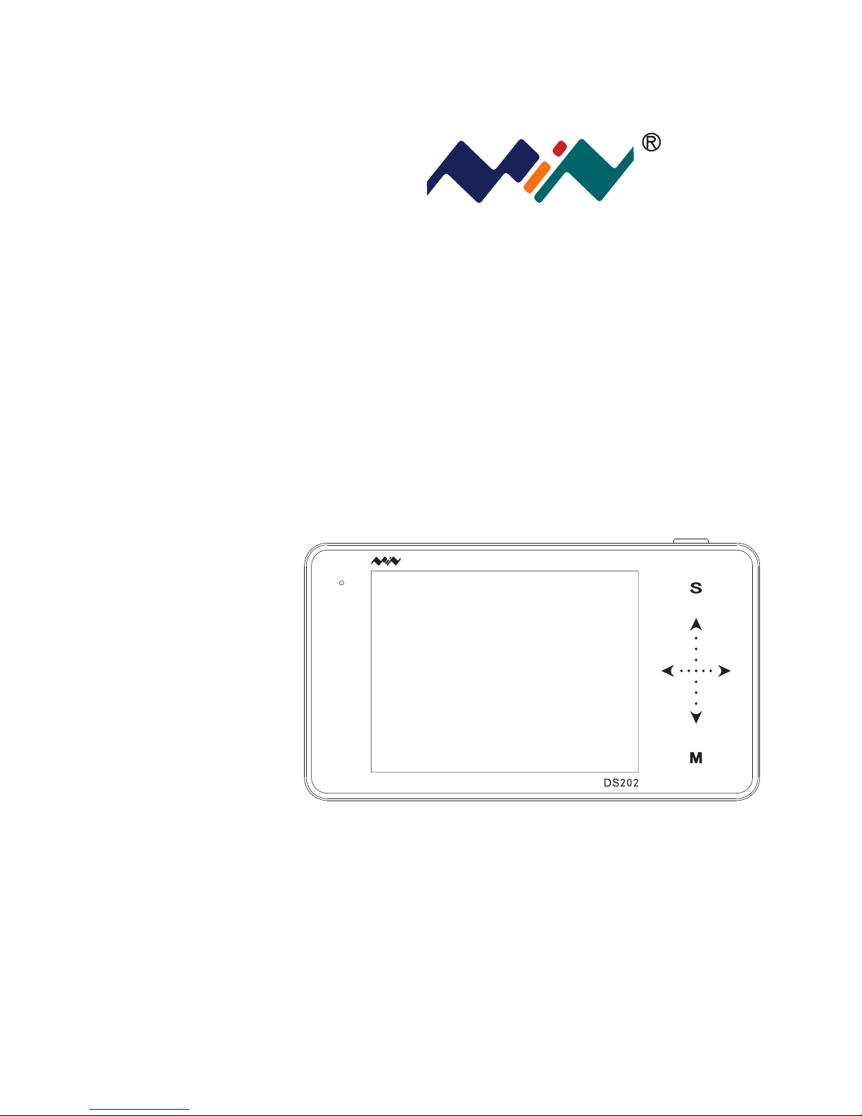
User Manual
Version 1.0
Page 2
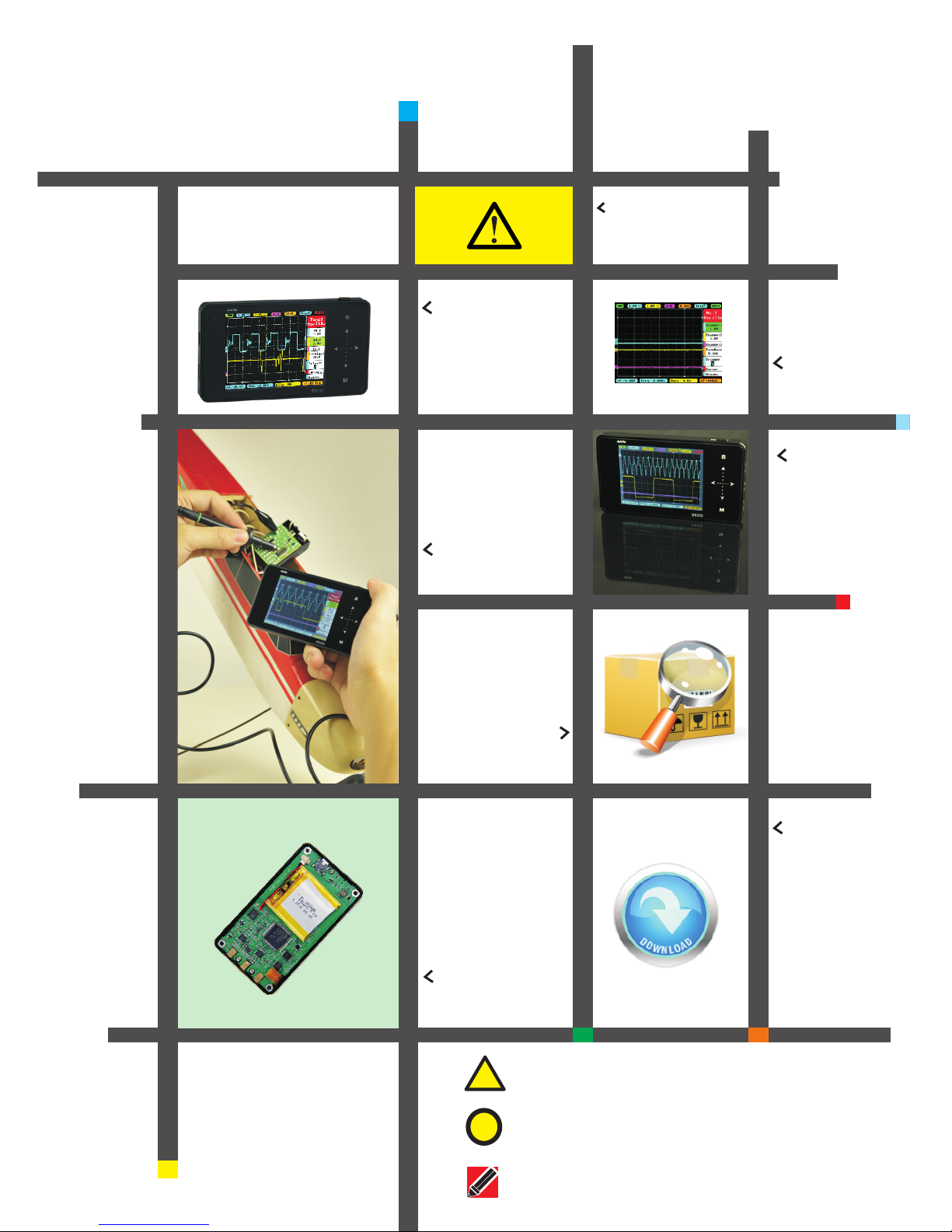
Contents
Impor tan t Safet y Inf orm at ion
P1
Chapt er 1 Ov ervie w of DS 202
P2
Chapt er 2 In trodu cti on to
Inter fac e
P6
Chapt er 3 St art Gui de
P9
Chapt er 4 Ba sic Fun cti on
P14
Chapt er 6 Ba ttery D isp osa l
P21
Chapt er 5 Pr oduct I nsp ect io n
P20
Chapt er 7 Tech nic al Supp ort
P22
!
War ning: Warnin g st ateme nt s ident if y conditi ons or prac ti ces
that coul d result in i nj ure you rs elf or othe rs
!
Caution : Caution s ta temen ts i dentify c onditio ns or pract ic es
that coul d result in d am age to yo ur d evice or ot her prope rty
Attenti on: Attent io n state me nts ident ify annot ations, u sa ge
tips or add itional i nf ormat io n
This user manual is
based onAPP V1.28
Page 3
1
● Read carefully all the following safety precautions to avoid personal injury
and prevent damage to the device or any products connected to it. Failure
to follow these safety instructions could result in personal injuries or risk of
fire.
● Use proper power cord. Please use power cord specified for this product and
certified for your country/district of use.
● Connect and disconnect properly. Do not connec t or d is co nn ec t pr ob e or t es t
leads while they are connected to voltage source. Disconnect the probe
input and the probe reference lead from the circuit under test before
disconnecting the probe from the measurement instrument.
● Observe all the terminal ratings. To avoid fire or shock hazard, please do not
measure signals at DC40V or above. Consult the product manual for further
ratings information before making connections to the device.
● Do not operate in wet/damp conditions.
● Do not operate in a potentially inflammable/explosive atmosphere.
● Please keep the surface of the product clean and dry.
Safety Statement
General Safety Information
Wa
r
n
in
g
Wa
rn
ing
Wa
rn
i
ng
Oper ating Envir onment
Temper ature
Oper ating Condi tion +0°C 到50°c:
Non- operating Condition: -20°c 到+60°c
Humidity
Oper ating Condi tion High Temperature:40°C 到 50°C,: 0% 到90%RH
: Low Temperature 0° C 到 40°C,10%到90%RH
Non- operating Condition: High t emperatur e:40°C 到 60°C,5%到95%RH
Low temperature:0° C 到 40°C,5%到95%RH
Requ irement
Operating Environment
Page 4
Performance parameters
Analog bandwidth
1MHz
Maximum sampling rate
10MSa/s
Maximum sample memory depth
8K
Analog input impedance
1MΩ
Maximum input voltage
±40V(X1 probe)
Coupling
AC/DC
Vertical Sensitivity
20mv/Div~10V/Div (in 1 -2-5 sequence step)
Horizontal time base speed
1uS/Div~2S/Div(in 1-2-5 sequence step)
Over view of DS202
Chapter 1
Specifications
2
Page 5
Over view of DS202
Chapter 1
Specifications
3
Functional parameters
Autonomous channel reveal
A,-B, A+B, A-B, RecA,RecB, RecC operation waveform
Mode
Contain Auto, Normal, Single,None, Scan synchron ous mode
Trigger mode
ascend/descend Edge trigger mode
Setting modes available
set adaptive level, vertical range, trigger threshold mode
Waveform Functions Auto measurement
frequency/cycle time /duty cycle, voltage peak-to-peak value/
effective value /maximum value /minimum value/average value
Signal Generator
10Hz~1MHz square wave (duty adjustable) or 10Hz~20KHz Sine/
Square/Triangle/Sawtooth wave
Product parameters
Memory capacity
Installed USB flash disk memory capacity 8MB,available for waveform
statistics and pictures
Battery
built-in 550mAhlithium battery, external USB port
Display
Color TFT LCD display (resolution320×240)
Touch key-press
Capacitive touch key-press input, support swipe gestures input
Dimension
Dimension( 100mm×56.5mm×10.7mm)
Page 6
4
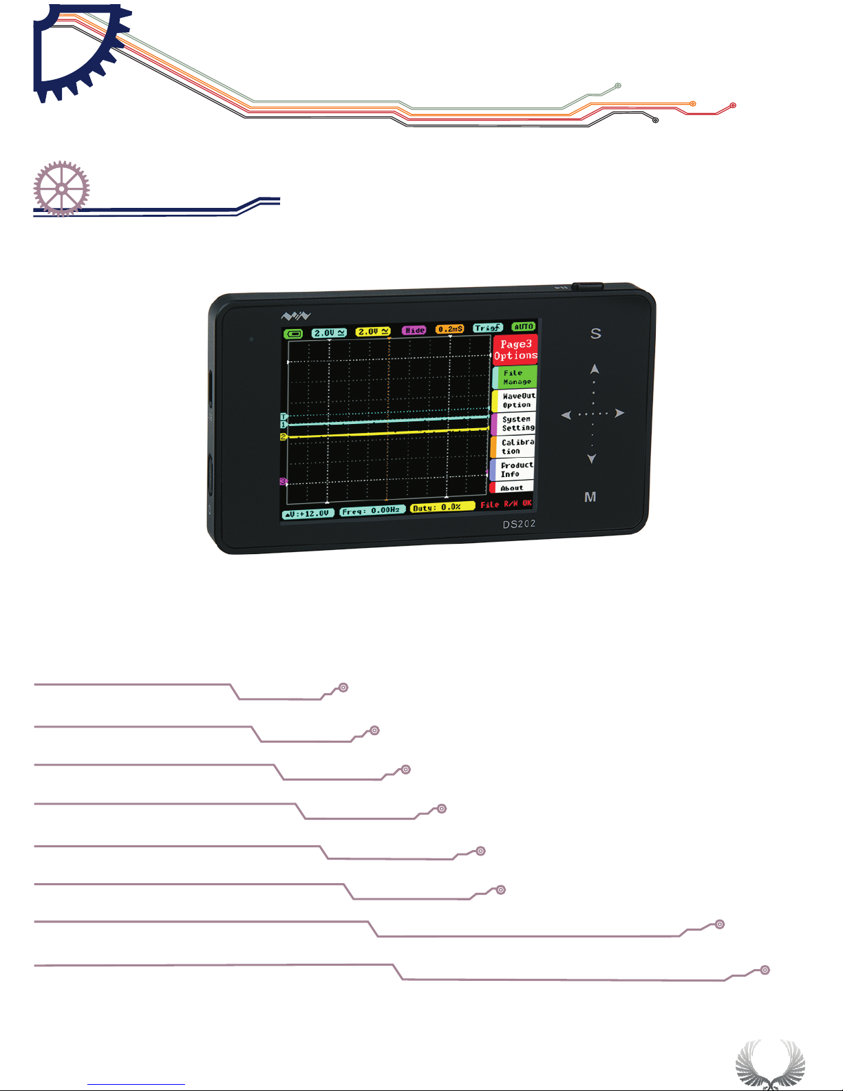
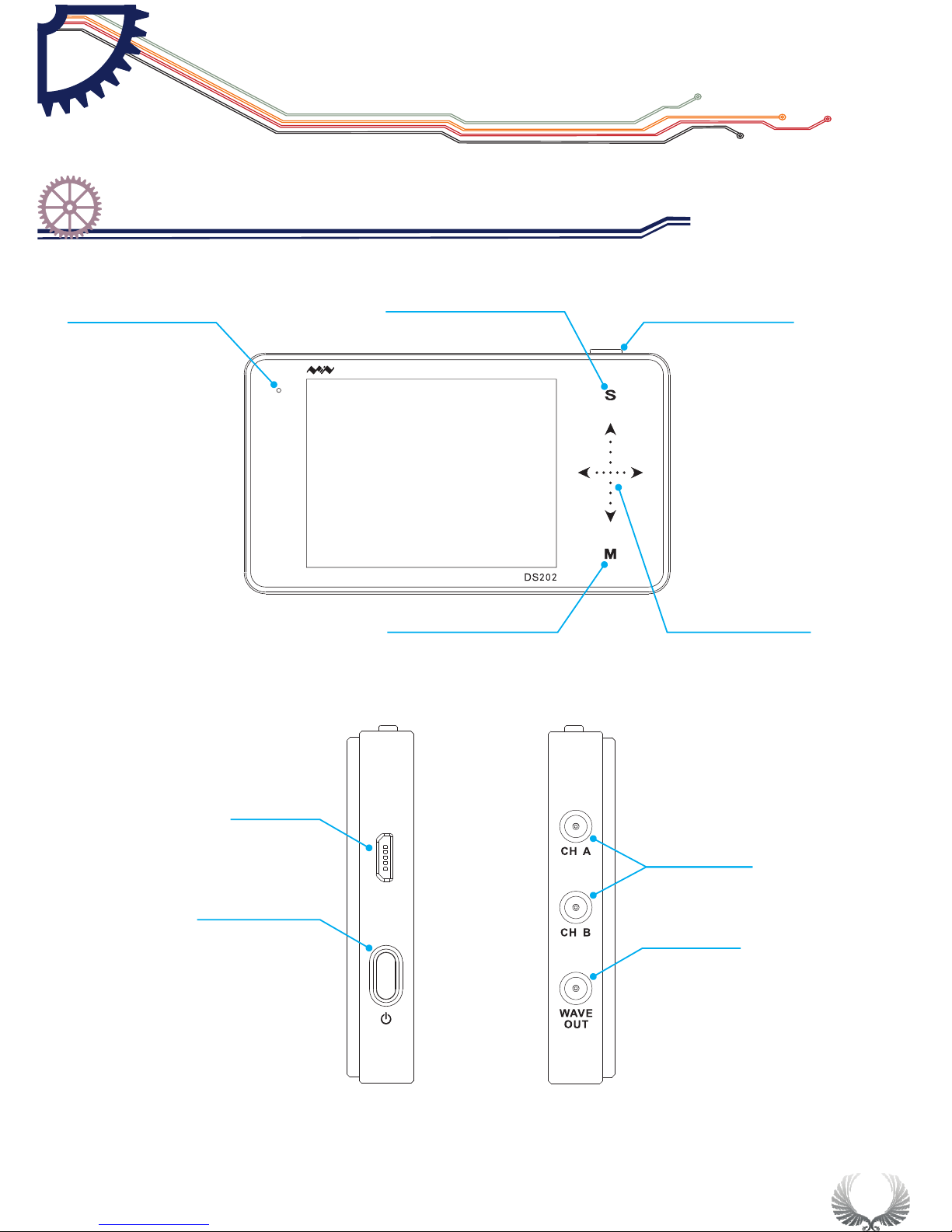
Run/pause button
Slide option area
Sub-menu selection
Charge indicator
Select and affirm&
Conceal/unfold menu
USB
Power Button
USB Port
Wave Out
Signal Input
Standby indicator
Introduction to device interface and key-press
Chapter 1
Over view of DS202
Page 7
5
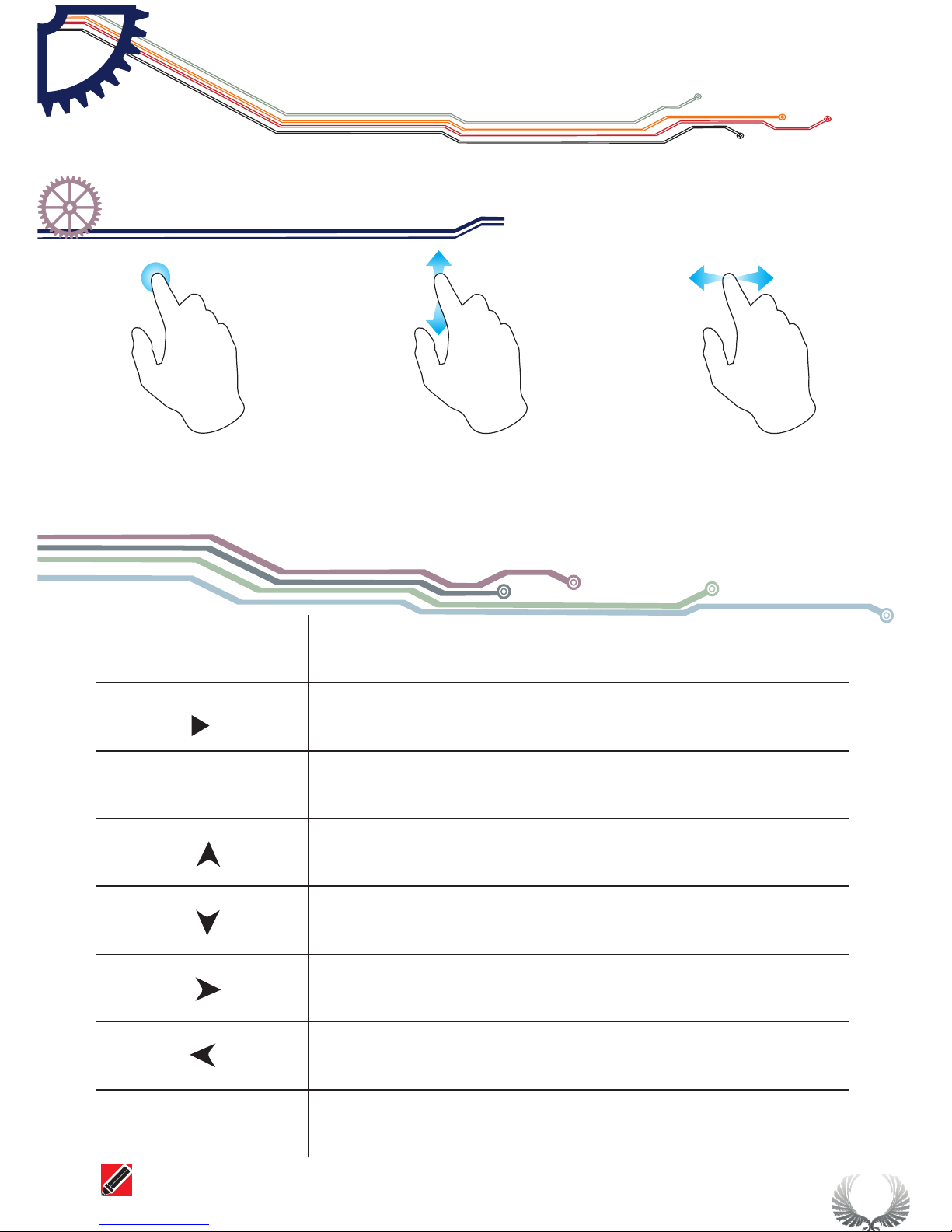
● Capacitive Touch key-press
● Support slide gesture input
● Tap
● Vertical slide ● Horizontal slide
Button
Function
1) Run/pause button
2) save current picture on screen(long press)
1) Display/Hide menu item
2) Sub-menu confirm
Upward selection(Slide Up)
Downward selection(Slide Down)
Reset Parameter(Tap Right/increase, slide Right)
Alter set up parameter(Tap Left/Reduce, Slide Left)
M
s
On/Off Sub-menu
Note that each item's color in Parameter Area is the same as that in Measurement Area
||
Operation on slide option area
Chapter 1
Over view of DS202
Page 8
6
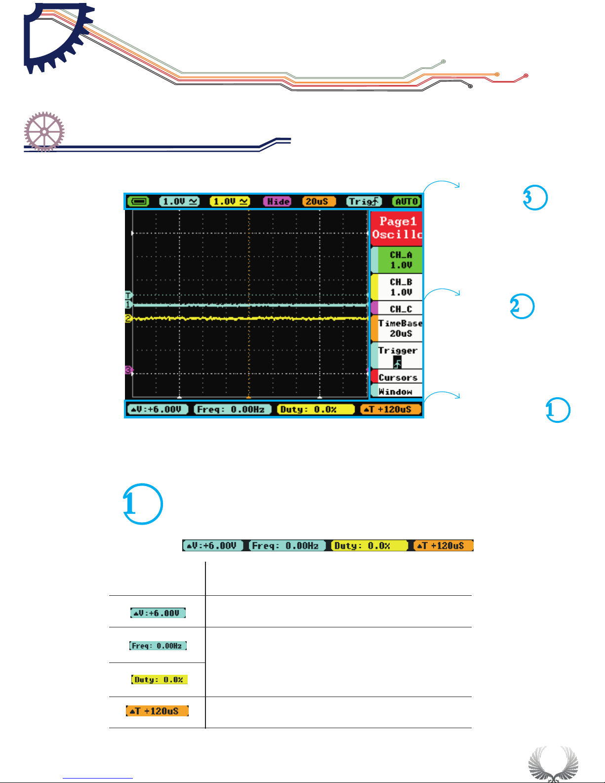
Home screen
Parameter area
Option area
Measurement area
Menu
function introduction
△
V=V1-V2
T=T2-T1
△
Measured Value( Blue corresponds with Channel A,
Yellow with Channel B) corresponding the 1st and
2nd item in Page2
Interface Introduction
Home screen introduction
Chapter 2
Measurement area introduction
Page 9
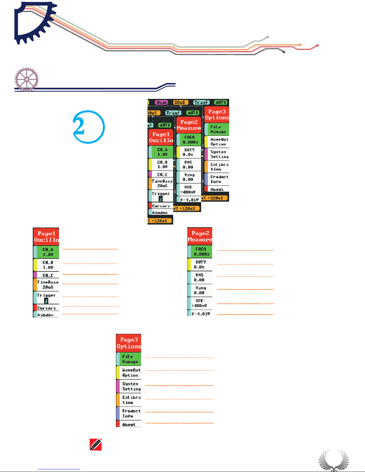
7
Page1( )oscilloscope
A channel option
Bchannel option
C channel option
Tim eB as e op ti on
Tri gg er o pt io n
Vernier option
Horizontal window
Page2( )Measurement
Frequency
Duty ratio
root-mean-square value
voltage average value
voltage peak-to-peak value
battery voltage
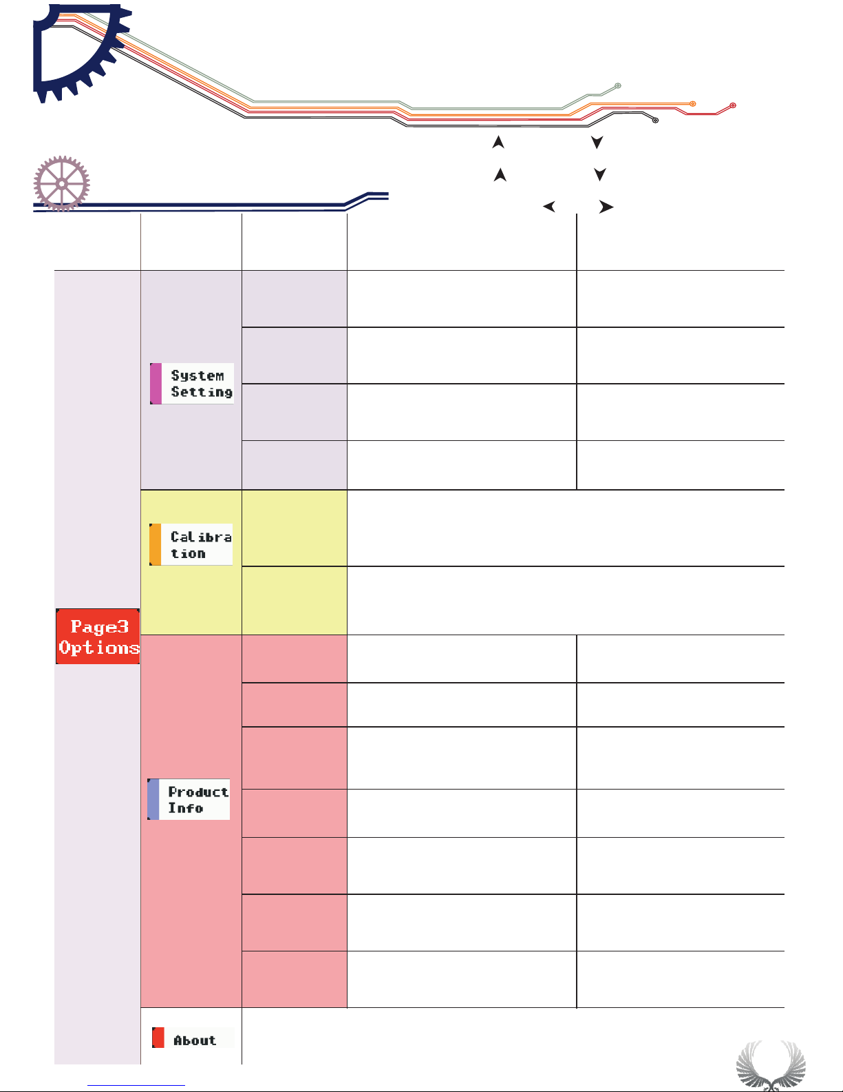
Page3( )option
File management
Output option
System settings
Adjusting option
Product information
relevant information
Annotation: detailed introduction to options refer to Page 13-18
Interface Introduction
Home screen introduction
Chapter 2
Option area introduction
Page 10
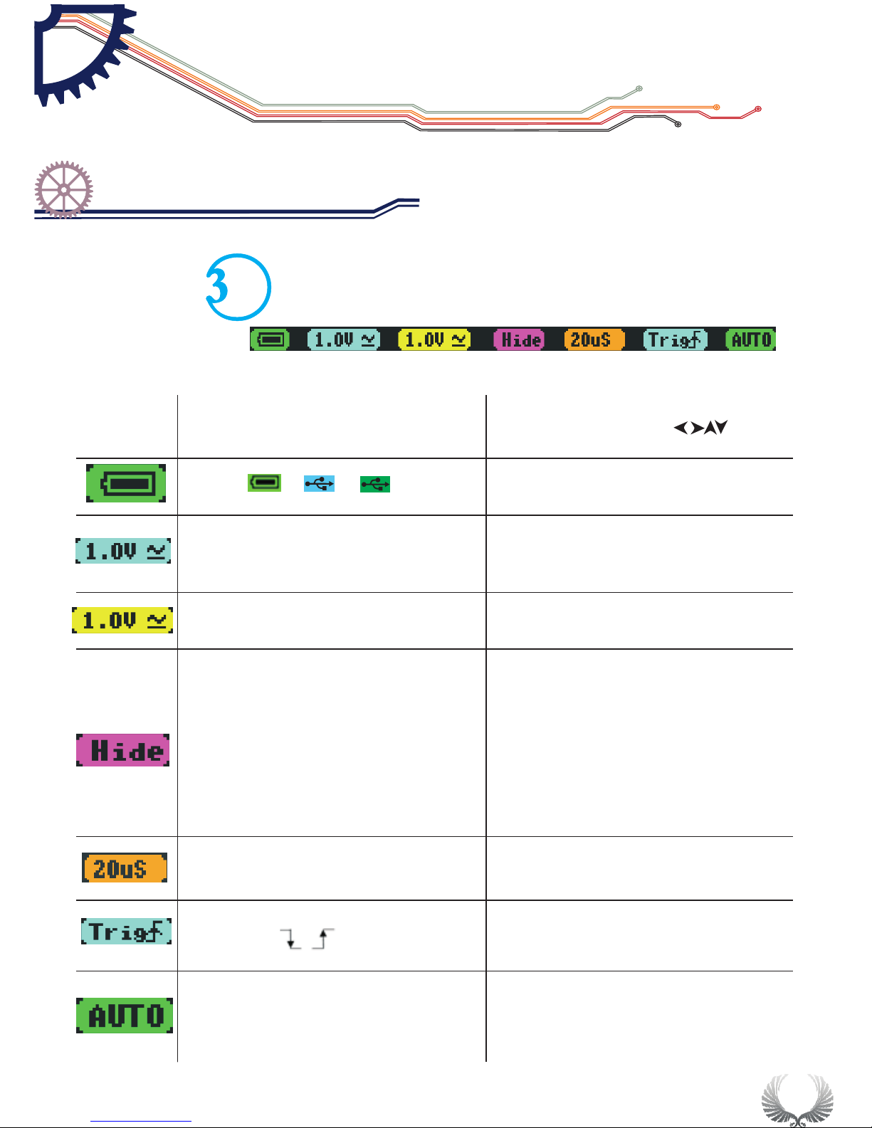
menu
opti ons
func tion(operation:pre ss ,slide)
Batt ery supply/ USB charging/full charge
/ /
20mV —10V(1-2- 5 )
AC/D C
sequ ence step
Chan nel A ordi nate unit amplitude,
AC/ DC c oupling met hod
20mV —10V(1-2- 5 )
AC/D C
sequ ence step
Chan nel B ordinate unit amplitude,
AC/ DC c oupling met hod
(-A) /(-B)/(A+ B)/(A-B)/
RecA /RecB/Rec C
(-A):
(-B):
(A+B):
(A-B):
RecA:
RecB:
RecC:
channel A waveform re ve rs e
channel B waveform reverse
addition of waveforms in channel A
and B
Subtraction of channel A waveform
and channel B waveform
Reload the previous saved waveform
in channel A
Reload the previous saved waveform
in channel B
RecC:Reload the previous saved
waveform in channel C
1.0u S—1S(1-2- 5 )sequ ence step
time u nit value
Trigger mode : ascend/ des cend trigge r mode
AUTO/NORM/SINGL/NONE/SCANSTOP
automatic/standard/single-pass/slow scan/ im me di at e
scan/operation/pause
8
Interface Introduction
Home screen introduction
Chapter 2
Parameter area introduction
Page 11
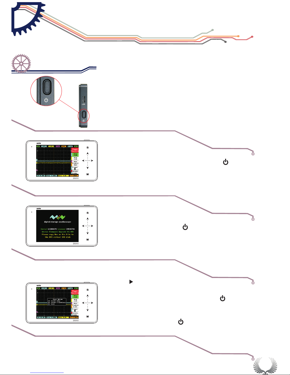
9
●Power On/Off Button
●In the shutdown state,press on Power Button" " for
approximately 2 seconds to start normally
Starting up
The default enter
into APP1
Upgrading/
Upgrade mode
●Press and hold Power button" "for approximately 4
seconds to enter into DFU mode
Forced Shut
Down
●Press“ ”Run/Pause”button to Power On and enter
APP2( if APP2 is not installed, then enter the DFU mode)
●In the Power On state, press Power button“ ”for
approximately 2 seconds to pop-up “Power Off” menu,
according Icon operation Choose Power Off. (In the
Power On state, long press“ ”Power button for 8
seconds to force Shut Down.)
||
Start Guide
Power On/Off
Chapter 3
Page 12
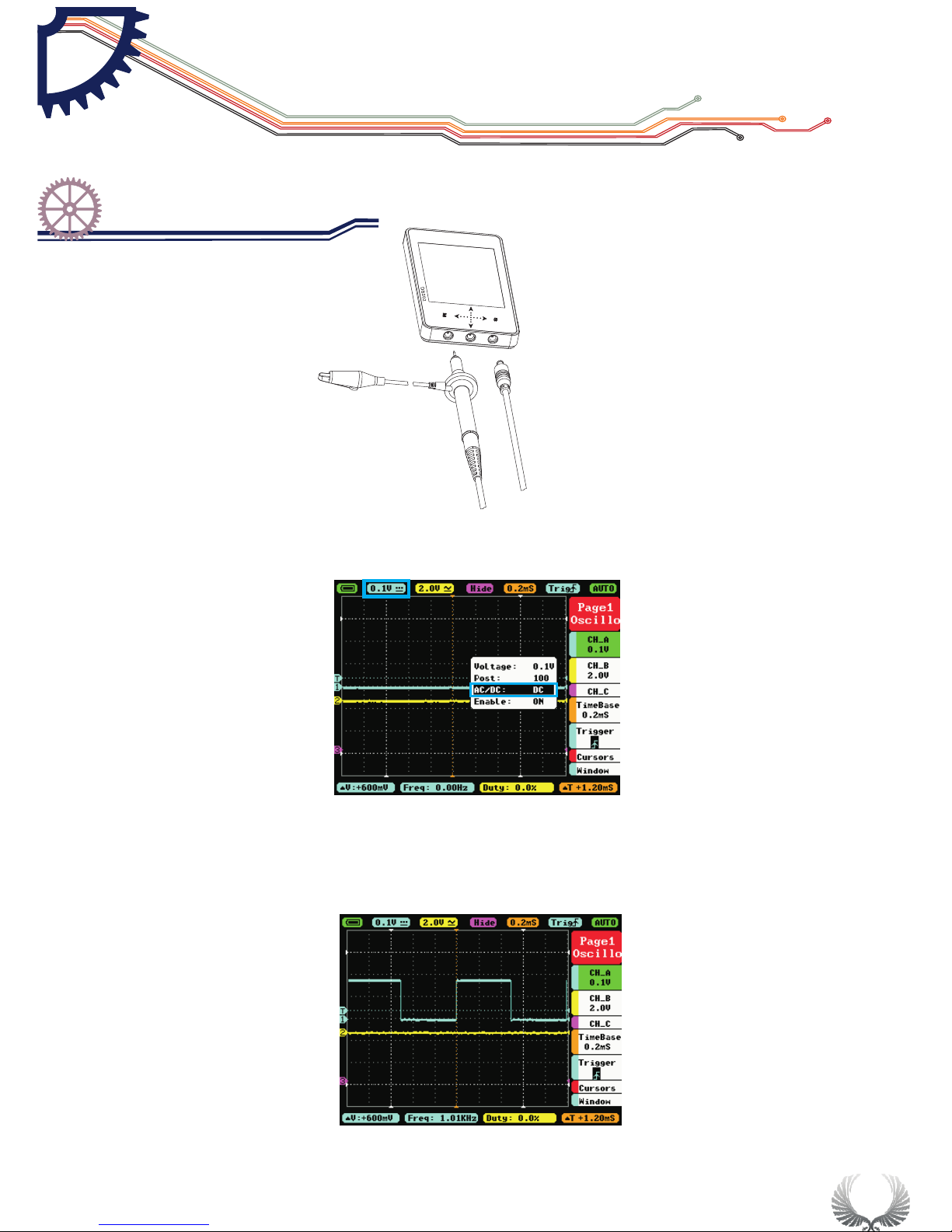
Connect probes to both the MCX and CHA input jacks
Adjust relevant parameters of CH A:
Adjust the DC mode in AC/DC function in CH A
Voltage adjustment: adjust probe X1 to 1V, adjust probe X10 to 0.1V
1.
2.
Measure WAVE OUT outlet waveform
10
Start Guide
Check up before use
Chapter 3
Page 13
11
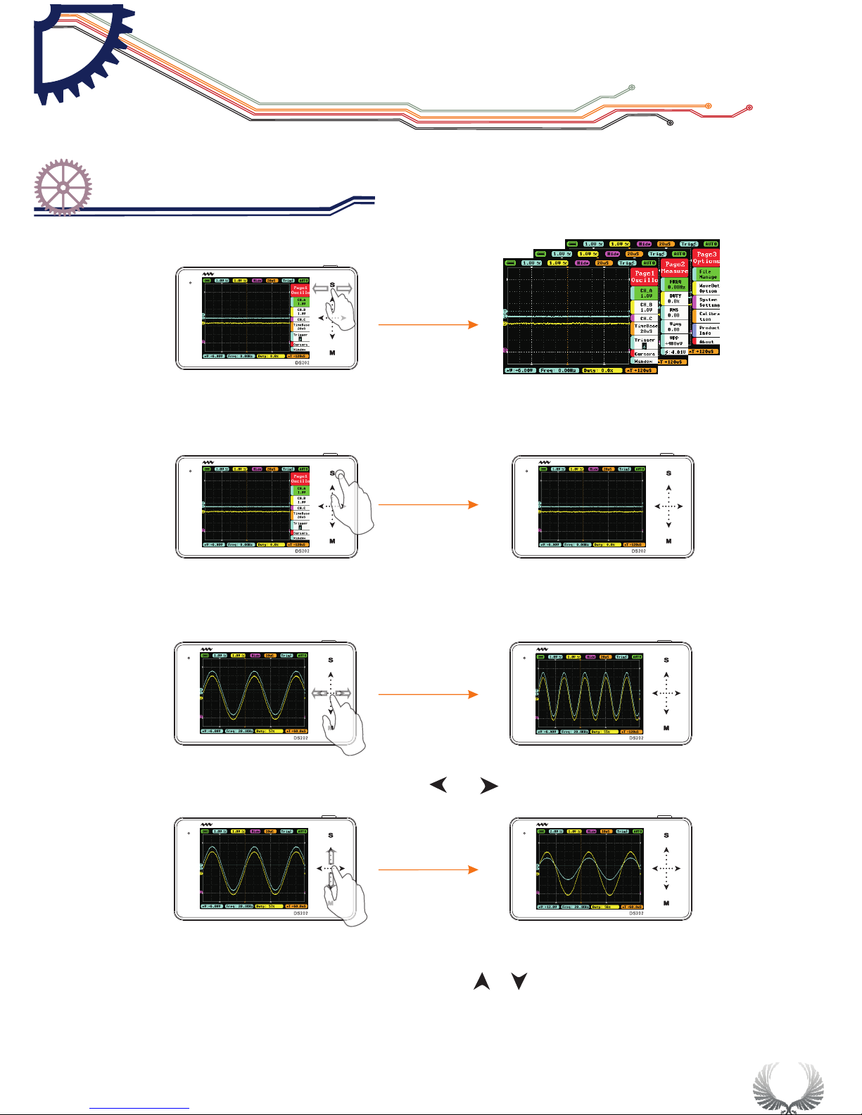
In the Main Menu interface, you can switch between the Main Menu pages by
sliding horizontally on the upper Touchpad.
In the Main Menu interface, tap “S” button to switch the Main Menu Display/ Hide
When the Main Menu is hidden, you can slide ••• horizontally to change the TimeBase
When the Main Menu is hidden, you can slide ··· vertically to change voltage
(shortcut for Channel A only)
Start Guide
Operation introduction
Chapter 3
Page 14
12
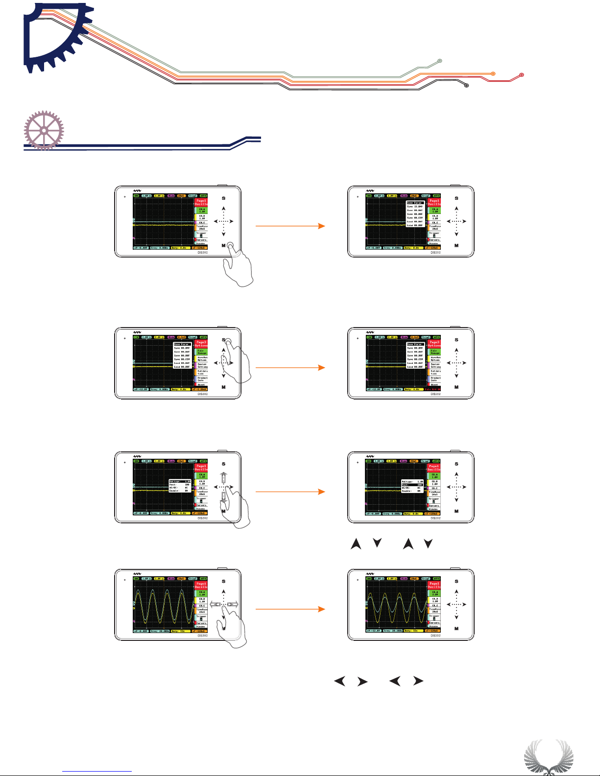
In the Main Menu interface, tap “M” button to switch the Sub-menu to Display/Hide
In the Sub-menu interface, tap “S” button to confirm the selection of operation
In the Main Menu or Sub-menu interface, tap " "" "or" "" " slide vertically
to select items upward or downward
In the Main Menu or Sub-menu interface, tap" "" "or" " " "slide horizontally
to adjust the Menu parameters( When you move Positions in Sub-menu interface,
tap and hold your finger for continuous operation)
Start Guide
Operation introduction
Chapter 3
Page 15
13
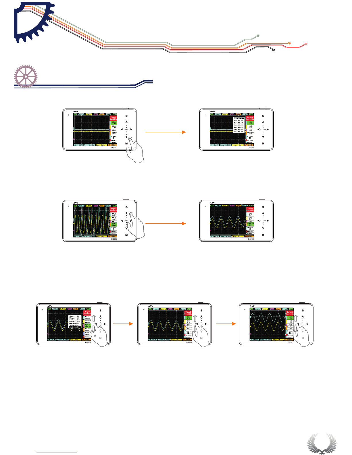
In the Main Menu or Sub-menu interface,tap and hold an non-button identification
area to Display/Hide file management sub-menu
When you turn on “Auto Fit” in “Trigger”, double-tap the non-button identification
area, the device will adjust automatically the amplitude, the time base and the trigger grid.
In the System Setting interface, when “PostSlide” is ON, slide up/down vertically the
touchpad in the left to adjust the position.
Start Guide
Operation introduction
Chapter 3
Page 16
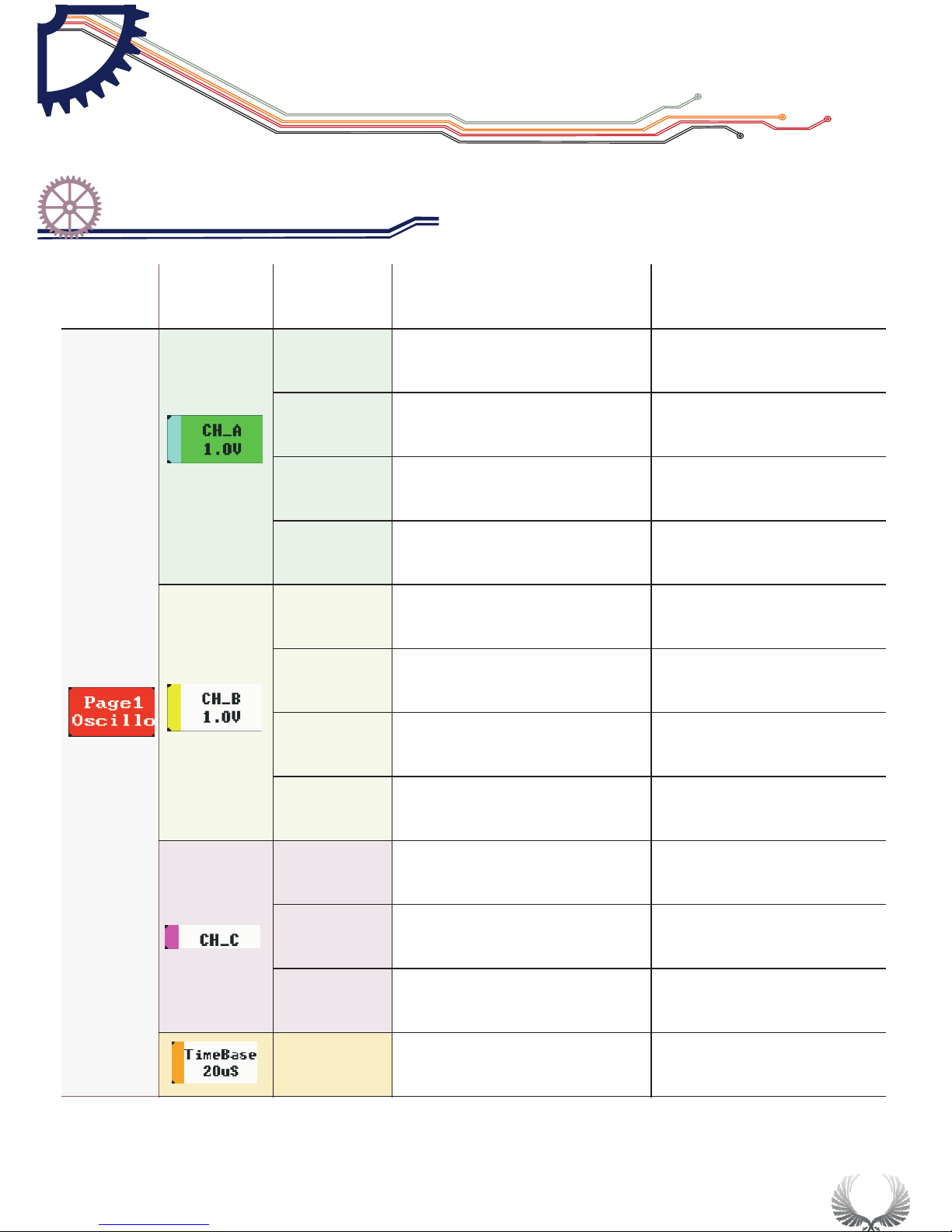
Voltage
Channel A y-axis voltage
per grid
20mV /50mV/0.1 V/0.2V/0.5V/
1.0V /2.0V/5.0 V/10V
Post
Adjust Channel A waveform position
upward/downward in the window
Position:5-195
AC/DC
channel A coupling
AD/DC
Enable
channel A display/hide
ON/OFF
Voltage
Channel B y-axis
voltage per grid
20mV/50mV/0.1V/0.2V/0.5
V/1.0V/2.0V/5.0V/10V
Post
Adjust Channel B waveform position
upward/downward in the window
Position: 5-195
AC/DC
channel B coupling
AD/DC
Enable
channel B display/hide
ON/OFF
Match
Calc ulation between CH_A
wave form and CH_B waveform
–A,-B,A+B,A-
B,RecA,RecB,RecC
Post
Adju st CH_C wavef orm position
upwa rd/downward in the window
Position: 5-195
Enable
CH_C display / hide
ON/OFF
TimeBase
TimeBase X-axis
voltage per grid
1.0us-2.0s(1-2-5 )step
Menu Options
Functions
Annotation for functions
Options for function
and annotation
Page1
Oscillo
14
Basic Function
Specific Parameter Intro
Chapter 4
Page 17
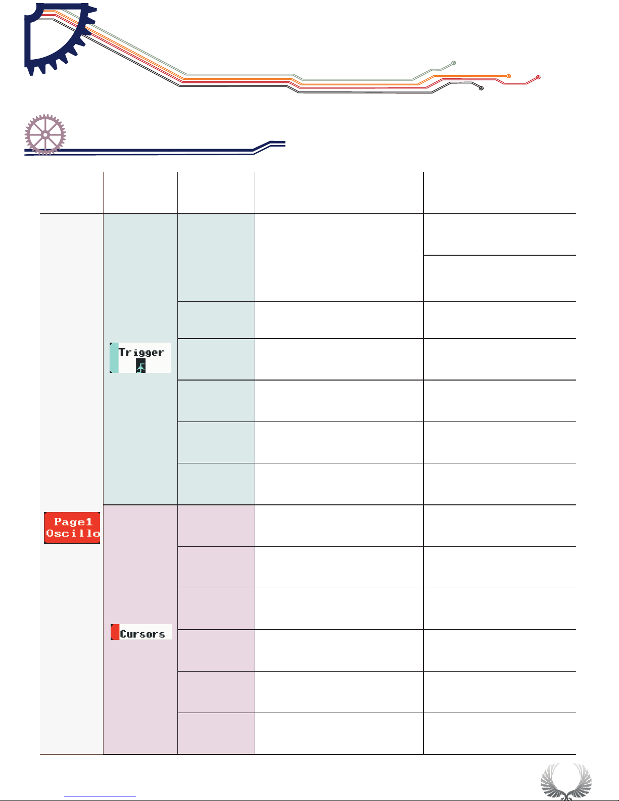
15
Syncmode
Selection for
synchronous mode
AUTO/NORM/SINGL/
NONE/SCAN
Auto matic /stan dard /
sing le pass /slow s can/
imme diate scan
Trigmode
Selection for trigger mode
Rising/falling edge
Source
Selection for
trigger channel
CHA/CHB
Threshol
Horizontal Triggering
Position Level
Position:5-198
Enable
Display/Hide Horizontal
Triggering Position Level
ON/OFF
Auto Fit
Automatic adjustment
ON/OFF
T1.Post
Time measurement
cursorT1
Position: 5-248
T2.Post
Time measurement
cursor T2
Position:5-248
Enable.T
Show/hide Time
measurement cursor
ON/OFF
V1.Post
voltage measurement
cursor V1
Site selection: 5-198
V2.Post
voltage measurement
cursor V2
Site selection:5-198
Enable.V
Show/hide voltage
measurement cursor
CHA/CHB/OFF
Page1
Oscillo
Menu
options
function
Annotation for functions
Options for function
and annotation
Basic Function
Specific Parameter Intro
Chapter 4
Page 18
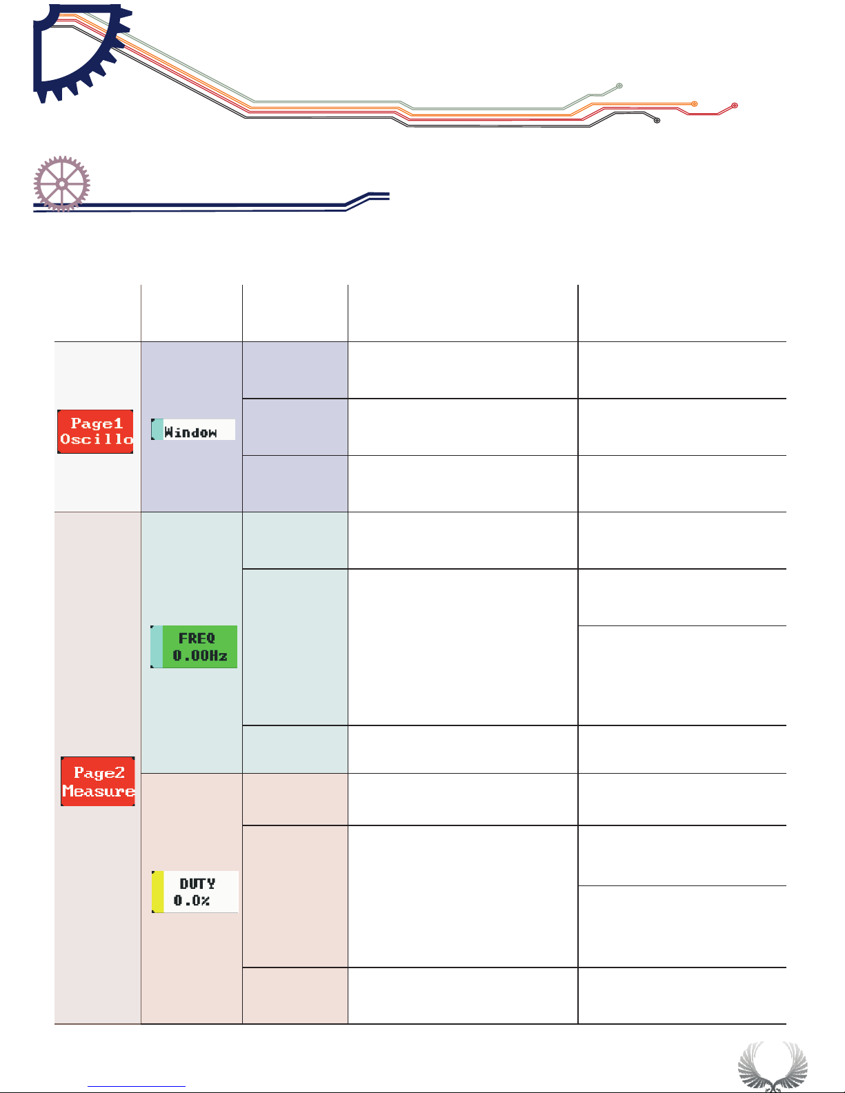
16
Post
Move horizontally
to check waveform
Select by storage depth
Depth
Internal storage depth
1k~8k
Enable
Show/hide event trigger
line vernier
ON/OFF
Source
Select measurement
channel
CHA/CHB
Type
Select measurement type
FREQ/DUTY/RMS/
Vavg/Vpp/Vmax/Vmin
Sign al frequency/duty ratio,
effective voltage v alue
/ave rage value/peak-to-peak
valu e/maximum
valu e/minimum v alue
Enable
Disp lay/hide
meas urement win dow
ON/OFF
Source
Select measurement
channel
CHA/CHB
Type
Select measurement type
FREQ/DUTY/RMS/
Vavg/Vpp/Vmax/ Vmin
Sign al frequency/duty
rati o,effective voltage
valu e/average value/peak-to-
peak v alue/maxi mum
Enable
Display/hide
measurement window
ON/OFF
Page1
Oscillo
Menu item
options
Annotation for functions
Options for function
and annotation
Page2
Measure
Basic Function
Specific Parameter Intro
Chapter 4
Page 19
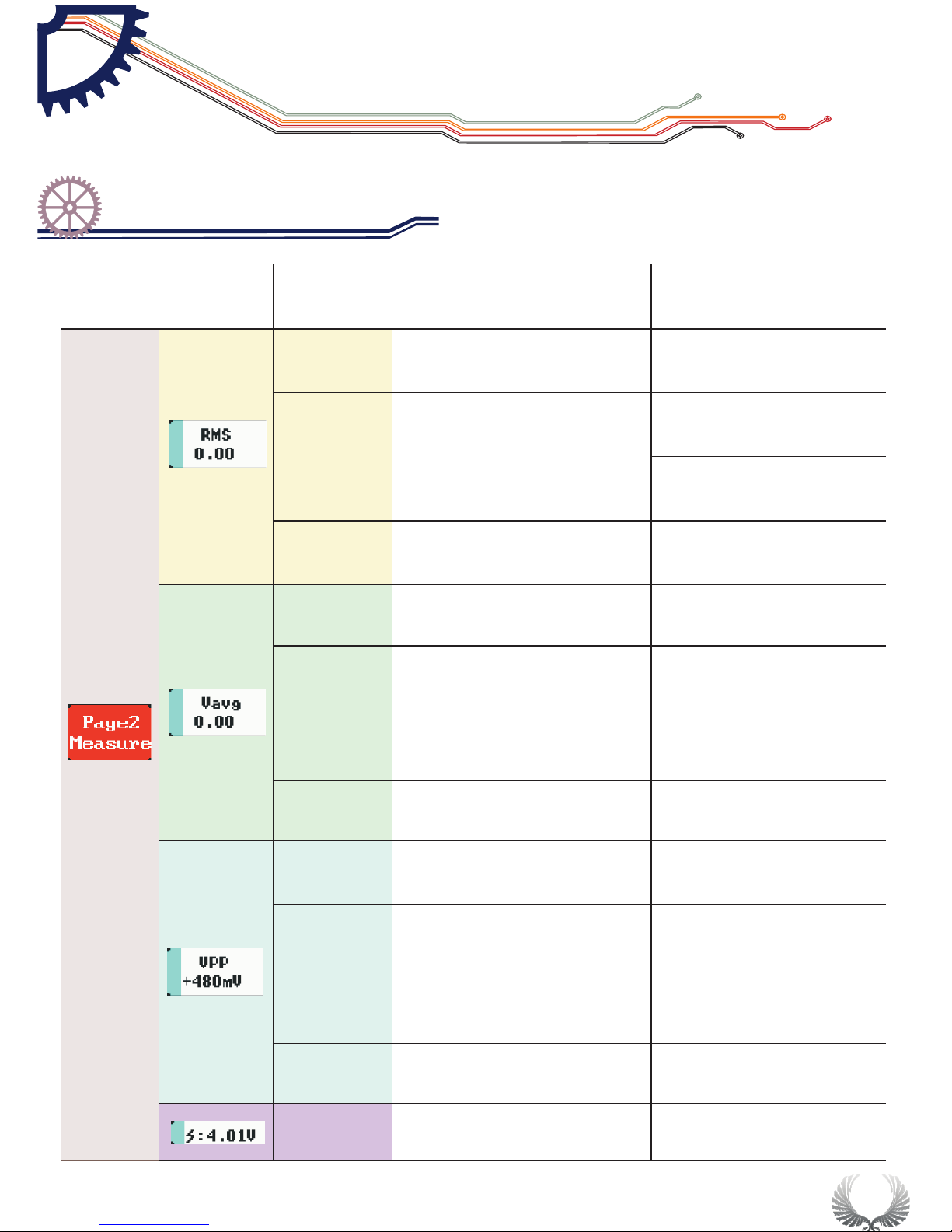
17
Source
Select measurement
channel
CHA/CHB
Type
Select measurement type
FREQ/ DUTY/ RMS/
Vavg/ Vpp/ Vmax/ Vmin
Signal fr equency /d uty rat io ,effe ctive
voltage v alue /ave ra ge valu e/ peak-to peak valu e/maxim um
Enable
Display/hide
measurement window
ON/OFF
Source
Select measurement
channel
CHA/CHB
Type
Select measurement type
FREQ/ DUTY/ RMS/
Vavg/ Vpp/ Vmax/ Vmin
Signal fr equency /d uty rat io ,effe ctive
voltage v alue/av er age val ue /peak-t opeak valu e/maxim um
Enable
Display/hide
measurement window
ON/OFF
Source
Select measurement
channel
CHA/CHB
Type
Select measurement type
FREQ/ DUTY/ RMS/
Vavg/ Vpp/ Vmax/ Vmin
Signal fr equency /d uty rat io , effec tive
voltage v alue/av er age val ue /peak-t opeak valu e/maxim um
Enable
Display/hide
measurement window
ON/OFF
Vbat
Battery voltage
Menu
options
function
Annotation for functions
Options for function
and annotation
Page2
Measure
Basic Function
Specific Parameter Intro
Chapter 4
Page 20
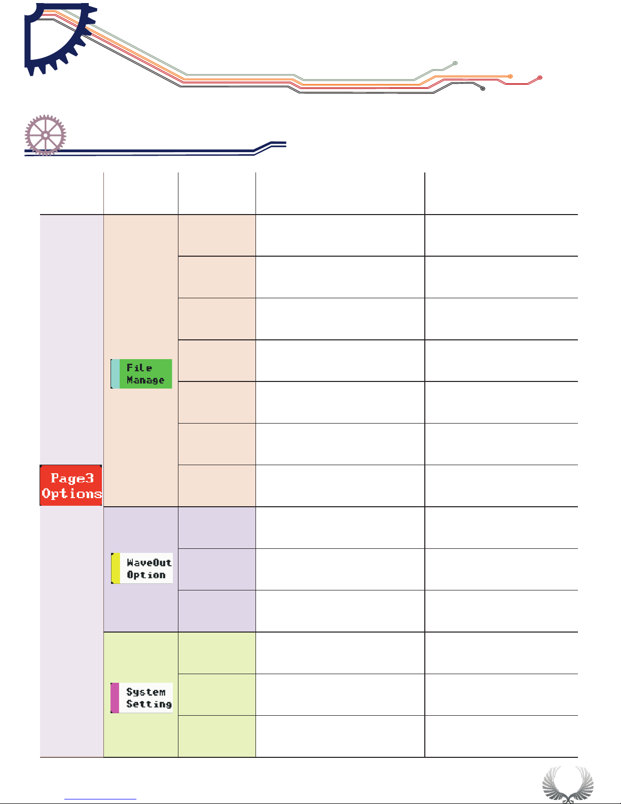
18
Save
Param
Save current
parameter settings
Tap “S”button to Save
Save Bmp
Save bmp file (waveform image) to
the built-in U disk.(Shortcut: long
press”Run/Pause”button
Tap “S”button to Save
Save Dat
Save dat file to built-in U
disk
Tap “S”button to Save
Save Buf
Save buf file (sampling data in
buffering area) to built-in U disk
Tap “S”button to Save
Save Csv
Save csv file (export sampling data in
buffering area) to built-in U disk
Tap “S”button to Save
Load Dat
Load dat file
Tap “S”buttonLoad files
Load Buf
Load buf file
Tap “S”buttonLoad files
Type
Output signal type
squar/sine/triangle
/sawtooth
Freq
Output signal frequecy
Duty
Output signal duty cycle
10%-90%
Volume
Adjust buzzer volume
0%-90%
Blight
Adjust backlight brightness
10%-100%
Standby
Adjust standby time
0min-30min
Menu
options
function
Annotation for functions
Options for function
and annotation
Page3
Setting
Squar(10Hz -1Mhz)sine/
triangle /sawtooth(10Hz-20kHz)
Basic Function
Specific Parameter Intro
Chapter 4
Page 21
PowerOff
Auto power off time
1min-30min
MenuCycle
Main menu options
circulation
ON/OFF
ItemCycle
Submenu options
circulation
ON/OFF
PostSlide
Sway site
ON/OFF
Calibrate
Zero
Press key “S” and self-calibration window pops up. Press
key “S” to carry out self-calibration and pop up when
calibration is finished, save calibration data
Restore
Data
Press key “S” to pop up factory reset window. Press key“S”
to carry out self-calibration and pop up when self-
calibration is finished and save factory data.
DeviceSN
SN number of the device
Hardware
Hardware version number
MCU Typy
Processor type
LCD Typy
Type of LCD
USB Disk
Volume of USB flash disk
DFU Typy
Version number of DFU
APP Typy
Version number of APP
Relevant satellite information
Menu
options
function
Annotation for functions
Options for function
and annotation
Page3
Setting
By the u pward down ward key or the options on
the sl iding option area, press M to unfold option settin g menu;
by the u pward down ward key or sliding the
para meter optio n needed to be set and change the current
para meter value b y the key o r sliding
“ ” “ ”
“ ” “ ”
“ ”or“ ”
19
Basic Function
Specific Parameter Intro
Chapter 4
Page 22
20
!
■ Long press on Power button“ ” for 8 seconds under any
circumstances will cause forced shutdown.
■ When the battery voltage status turns to o r d i s p l a y
brightness is relatively dim, please charge the battery in time.
Charging is available in both power-on and off mode. When the
battery is being charged, the LED will light on until the charging
process is finished.
“ ”
功能 检查
● When you get a new DS202 oscilloscope, you are advised to
inspect the product by the following steps.
● Inspect damages caused by shipping.
If the packaging carton or the protection pad is seriously damaged,
keep the package until the oscilloscope & accessories pass the
electrical and the mechanical test.
● Inspect the product.
Please contact the company if the following problems occur: 1)
product surface is damaged, 2) product doesn't work properly, 3)
product does not pass performance test.
If the damage is resulted from shipping, please keep the package
and contact the company for repair or exchange.
● Make a quick inspection of functions to ensure the device is working
soundly. Please perform following steps:
● Turn on power and access the homepage of the mini oscilloscope.
● Connect the oscilloscope with standard signals (e.g. square wave
20KHz, Vpp=5V), set the switch on probe tip as 1X, plug
oscilloscope probe to the Input Channal.Check whether the
measured signal value is the same as the standard value; it can be
calibrated if the margin is small.
常规 检查
Product Inspection
Instruction on battery
Chapter 5
Page 23
21
FCC statement of compliance
This device is complied with the regulation in the 15th part of FCC
regulation. The two conditions below should be satisfied if you want
to operate the device:
This device may not cause harmful interference.
This device must accept any interference received, include the
interference that may lead to undesired operation.
(1)
(2)
The CE mark is a registered trademark of European Community.
This CE mark shows that the product complies with all the relevant
European Legal Directives.
Do not dispose in domestice household waste
!
● This device complies with the WEEE Directive (2002/96/EC)
marking requirement. This affixed product label indicates that you
must not discard this electrical or electronic product in domestic
household waste.
● Disposal and recycling: you must dispose the mini oscilloscope
according to local law and regulations. As the oscilloscope contains
electronic building brick and battery, you must dispose it
respectively with garbage.
● Please dispose the battery in accordance with local
environmental regulations.
Battery Disposal
Regulatory Markings
Chapter 6
Page 24
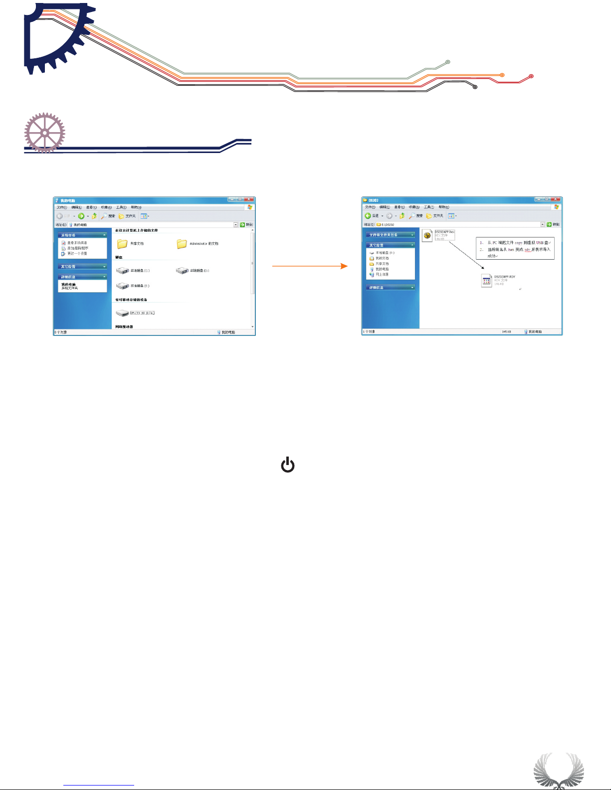
To upgrade the firmware of oscilloscope, please carry out the operation below:
Open web browser to visit www.minidso.com , download the newest firmware
appropriate to oscilloscope to your PC.
Press DS202's Power button for approximately 4 seconds to enter into
DFU firmware upgrading mode and the indicator light flickers.
Use USB data cord to connect DS202 to your PC, and a removable hard disk
named “DFU V3_40_D” will appear on your PC. Copy the hex firmware to the
root directory of that disk. After the extension of the firmware changes from
“hex” to “rdy”, restart DS202. Then the upgrading process is finished.
For more information, please visit
For more service and information, pleas visit
1.
2. “ ”
3.
www.minidso.com
http://www.minidso.com/forum.php
22
Technical Suppor t
Firmware upgrading
Chapter 7
 Loading...