

Mimosa Networks 010 00083 User Manual

Mimosa Backhaul
copyright © 2018 Mimosa. All rights reserved.
http://backhaul.help.mimosa.co/
The information contained in this document is subject to change without notice.
This document contains proprietary information which is protected by copyright.
All rights are reserved. No part of this document may be photocopied, reproduced,
or translated to another language without the prior written consent of Mimosa.

Mimosa Backhaul and B24 Help Content
Mimosa Backhaul LED Status Indicators
Table of Contents
Installation Guide 1 .......................................................................................................................................
Mounting & Grounding 1 ........................................................................................................................
B24 Mounting and Grounding 1 .......................................................................................................
B24 Installation, Mounting and Alignment 4 ....................................................................................
User Guide 7 ..................................................................................................................................................
Overview 7 .............................................................................................................................................
General 7 .........................................................................................................................................
Accessing the Interface 9 ................................................................................................................
Logging In 10 ...................................................................................................................................
User Interface Overview 11 .............................................................................................................
Dashboard 13 .........................................................................................................................................
Dashboard Overview 13 ..................................................................................................................
Signal Meter 14 ...............................................................................................................................
Aiming Mode 17 ...............................................................................................................................
Performance 19 ...............................................................................................................................
Device Details 21 ............................................................................................................................
MIMO Status 24 ...............................................................................................................................
Wireless 27 .............................................................................................................................................
Channel & Power 27 ........................................................................................................................
Spectrum Analyzer 27 ..............................................................................................................
Channel & Power Settings 29 ...................................................................................................
Exclusions & Restrictions 34 .....................................................................................................
Link 35 .............................................................................................................................................
TDMA Configuration 35 .............................................................................................................
Rate Adaptation 37 ...................................................................................................................
Link Configuration 38 ...............................................................................................................
Location 41 ......................................................................................................................................
Local Satellite Signals 41 ..........................................................................................................
Satellite Information 42 ............................................................................................................
Location Data 43 ......................................................................................................................
Site Survey 44 .................................................................................................................................
Survey Results 44 .....................................................................................................................
Preferences 45 .......................................................................................................................................
General 45 .......................................................................................................................................
Naming 45 ................................................................................................................................
Time 46 ....................................................................................................................................
Set Password 47 .......................................................................................................................
Miscellaneous 48 ......................................................................................................................
Management 50 ..............................................................................................................................
Management IP 50 ...................................................................................................................
Watchdog 51 ............................................................................................................................
Services 52 ...............................................................................................................................
Miscellaneous Settings 53 ........................................................................................................
Copyright © 2018 Mimosa Page

Mimosa Backhaul and B24 Help Content
Mimosa Backhaul LED Status Indicators
Network Interfaces 55 ..............................................................................................................
Management VLAN 57 ..............................................................................................................
2.4 GHz Console 58 .........................................................................................................................
2.4 GHz Network 58 .................................................................................................................
2.4 GHz Security 59 ..................................................................................................................
Notifications 60 ...............................................................................................................................
SNMP Notifications 60 ..............................................................................................................
SNMP Traps 61 .........................................................................................................................
SNMP Traps OIDs 63 .................................................................................................................
System Log Notifications 65 .....................................................................................................
System Log Traps 66 ................................................................................................................
Firmware & Reset 67 .......................................................................................................................
Firmware Update 67 .................................................................................................................
Reset & Reboot 68 ...................................................................................................................
Backup & Restore 69 .......................................................................................................................
Backup & Restore 69 ................................................................................................................
Diagnostics 70 ........................................................................................................................................
Tests 70 ...........................................................................................................................................
Test Overview 70 .....................................................................................................................
Ping 71 .....................................................................................................................................
Bandwidth 72 ...........................................................................................................................
Traceroute 73 ...........................................................................................................................
Logs 74 ............................................................................................................................................
Log Overview 74 .......................................................................................................................
Troubleshooting Guide 75 .............................................................................................................................
LED Status Indicators 75 ........................................................................................................................
B24 LED Status Indicators 75 ..........................................................................................................
Copyright © 2018 Mimosa Page
Mimosa Backhaul and B24 Help Content Mimosa Backhaul Mounting & Grounding
Mounting and Grounding the B24
Only a shielded, outdoor rated CAT 6 FTP Ethernet cable shall be used with all Mimosa products. Mimosa
Only a shielded, outdoor rated CAT 6 FTP Ethernet cable shall be used with all Mimosa products. Mimosa
will not warrant any product which has been installed without the use of shielded CAT 6 Ethernet cable
will not warrant any product which has been installed without the use of shielded CAT 6 Ethernet cable
and/or proper earth grounding.
and/or proper earth grounding.
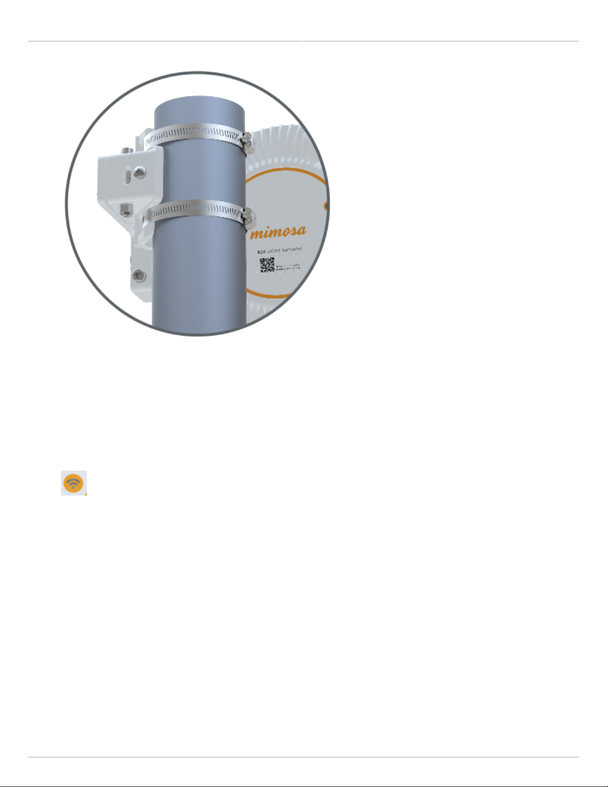
This process ensures that the radio is securely attached to a mast/pole up to 90 mm (3.5 inches) in
This process ensures that the radio is securely attached to a mast/pole up to 90 mm (3.5 inches) in
diameter, and grounded to protect against electrical discharge.
diameter, and grounded to protect against electrical discharge.
Follow these steps to mount and ground the B24 Radio.
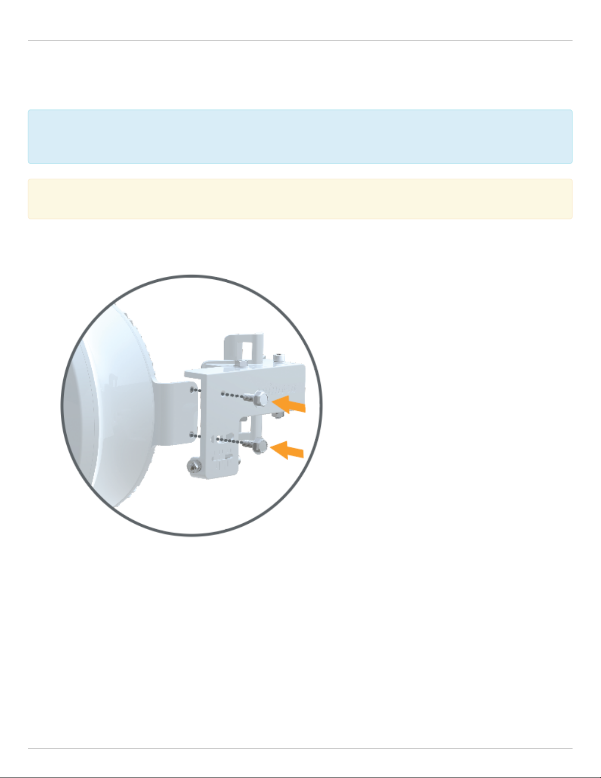
Attach the precision alignment mount to the bracket with the provided bolts.1.
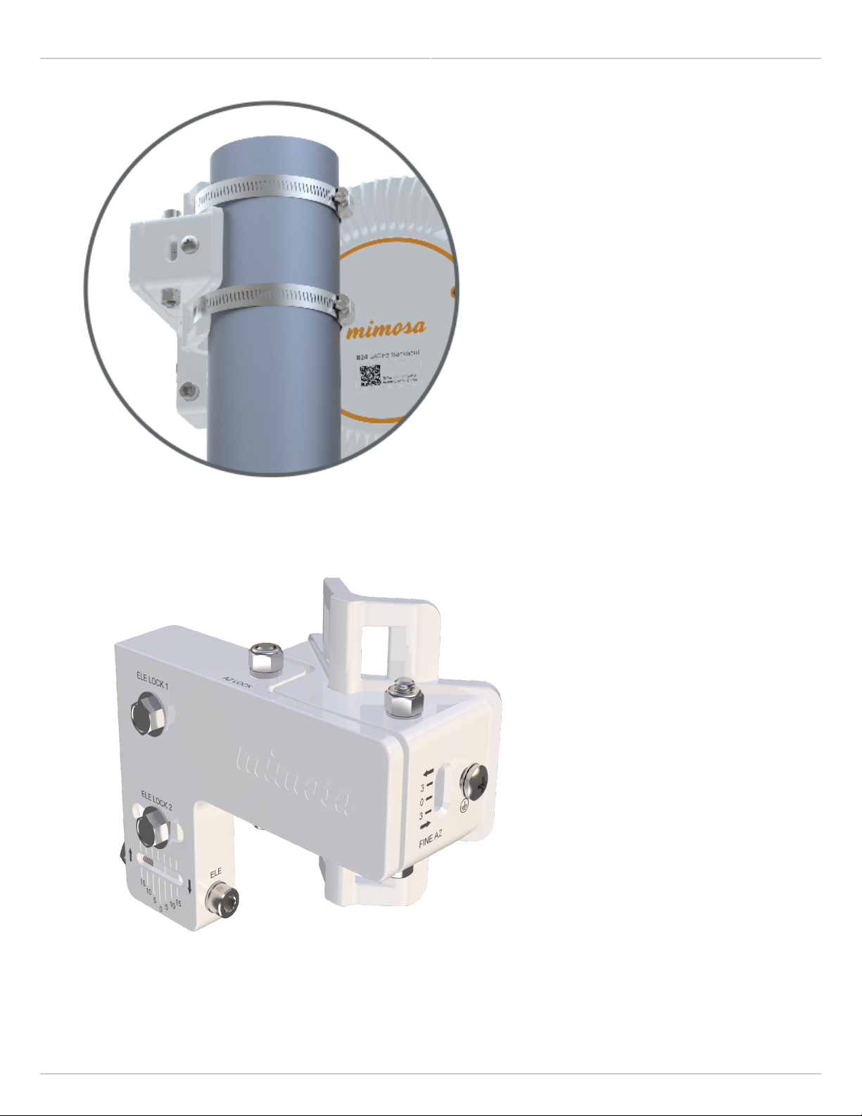
Attach the mount to your desired pole using the provided pole clamps.2.
Copyright © 2018 Mimosa Page Page 1
Mimosa Backhaul and B24 Help Content
Mimosa Backhaul Mounting & Grounding
Aim the radio horizontally by sliding the the mount around pole until it is pointing in the desired direction. To3.
fine tune the radio, use the Elevation and Azimuth adjustment allen bolts, then check and tighten each of
Elevation and Azimuth locking bolts.
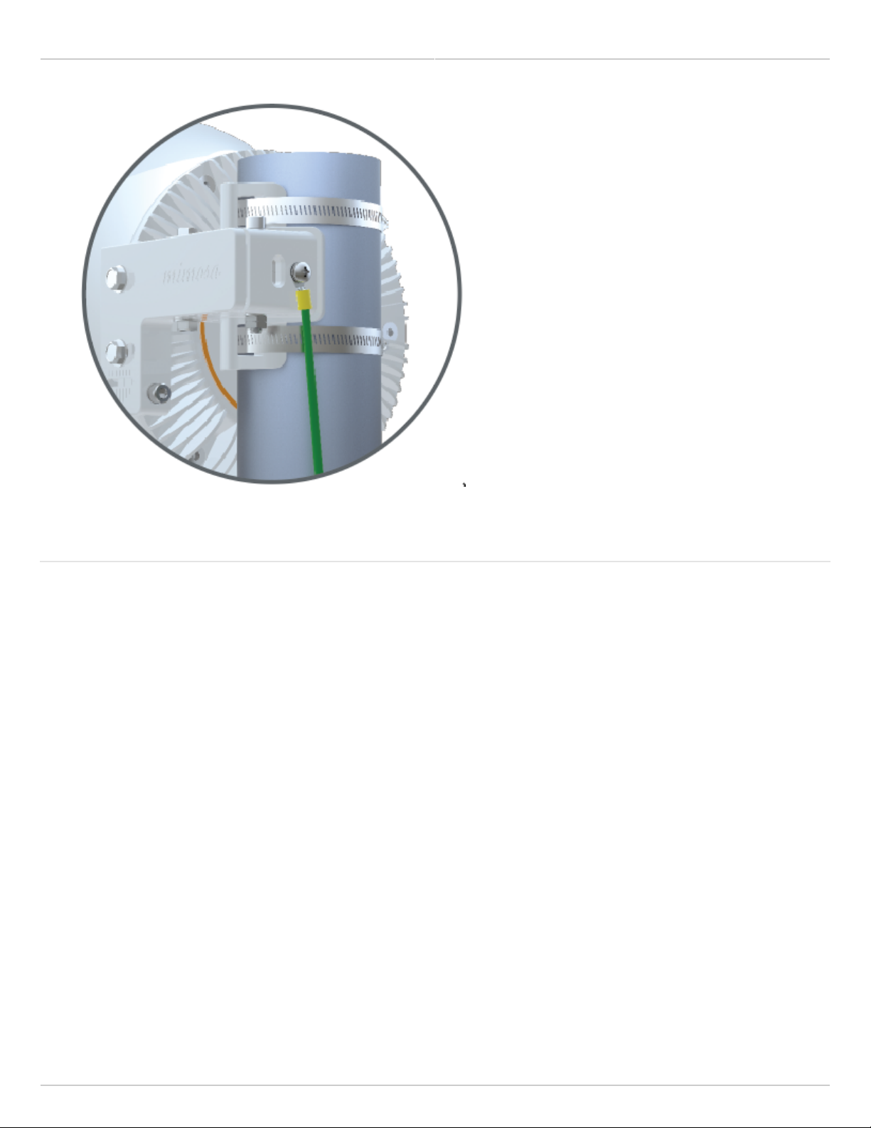
Attach a 6 mm2 (10 AWG) ground wire with a maximum length of 1 m (3.3 feet) between the mounting bracket1.
of the B24 and a suitable grounding location on the tower or structure. The provided grounding screw is M5 x
6mm with 0.8 thread.
Copyright © 2018 Mimosa Page Page 2
Mimosa Backhaul and B24 Help Content
Mimosa Backhaul Mounting & Grounding
Related
B24 Specifications - See specification sheet section entitled, "Physical" for additional mounting hardware details.
Hardware & Materials - Details about what materials are used in each provided part.
Copyright © 2018 Mimosa Page Page 3
Mimosa Backhaul and B24 Help Content
Mimosa Backhaul Mounting & Grounding
Installation, Mounting and Alignment
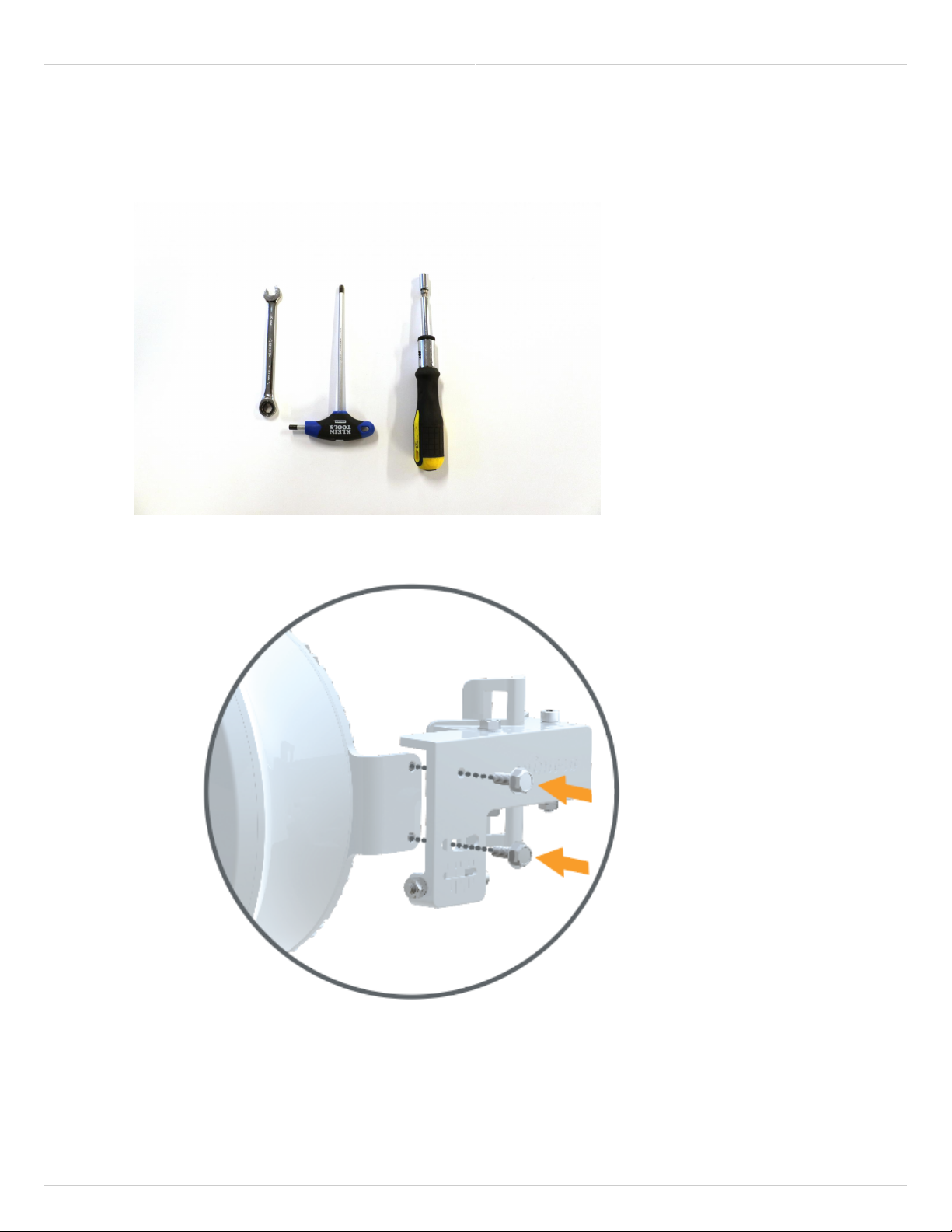
You will need a 10mm wrench, a #5 hex wrench/allen wrench, and a 5/16 nut driver to mount and align the1.
B24.
Take the mounting bracket and attach it to the B24 using the two provided screws. Use your 10mm wrench2.
to tighten the screws down. When you’re ready to adjust elevation, these two screws will need to be
loosened up.
Add both hose clamps to the B24 mount when you’re ready to mount to a pole, j-mount, etc.3.
Once on the pole, tighten down your hose clamps most of the way so that they hold the radio up on the pole.4.
Copyright © 2018 Mimosa Page Page 4
Mimosa Backhaul and B24 Help Content
Mimosa Backhaul Mounting & Grounding
Before tightening your hose clamps down all the way, go ahead and point your B24 toward the other end of5.
the link (coarse alignment). Once you have your radios pointed, go ahead and tighten down the hose clamps.
If you have planned this link out in the Mimosa Design Tool, you will know the -+ degree of the elevation. Go6.
ahead and set your mount to around the correct angle. Keep in mind that each tick mark for elevation is 5
degrees.
Power up the B24 radio so that you can connect to the radio GUI through 2.4GHz Wi-Fi or Ethernet. Once the7.
radios are powered up, you should be able to tell if the radios are linked up or not by looking at the LED light
on the back. If you have a blue flashing light, your link is connected.
Regardless if your link is connected or not, log into the radio and access the radio GUI. On the Dashboard8.
page, you will see the Signal Meter. If connected, you’ll have a signal level listed. Please make sure you are
only adjusting one radio at a time. Also make sure you are not adjusting azimuth and elevation at the same
time. You want to complete one before starting the other.
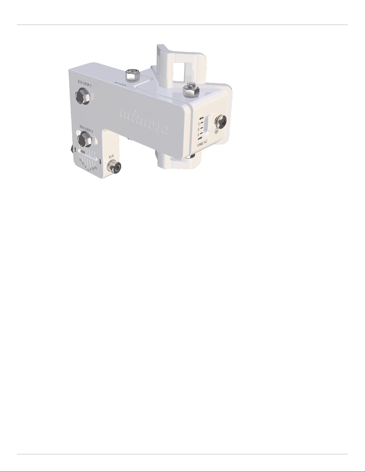
Now that the radio is powered up, and you’re logged into the radio, you can start the fine adjustment9.
process. Loosen up the hex head screw labeled “AZ LOCK” using your #5 hex wrench and your 10mm
wrench. Failure to loosen this screw will prevent you from adjusting the horizontal/azimuth on your B24
mount.
Now take your hex wrench and insert it into the hex screw labeled “FINE AZ”. Turning clockwise will move10.
your radio to the left, while turning counter-clockwise will move your radio to the right. Pick a direction and
start turning. Watch the signal meter to see if your signal is getting better or worse.
Copyright © 2018 Mimosa Page Page 5
Mimosa Backhaul and B24 Help Content
Mimosa Backhaul Mounting & Grounding
Even if your signal is getting better or
worse, continue turning for a few more turns to determine if you’re connected to a side lobe or not. If you are
the signal will get worse and then much, much better.
Once you have adjusted left and right, move back to where you had the best signal.11.
To adjust elevation, make sure to loosen the two 10mm bolts labeled “ELE LOCK”. If you recall, these were12.
the two bolts used to attach the mount to the B24.
Take your hex wrench and insert it into the hex screw labeled “ELE”. Turning clockwise will reduce the13.
elevation of your radio, while turning counter-clockwise will increase the elevation of your radio. Pick a
direction and start turning. Watch the signal meter to see if your signal is getting better or worse. Even if
your signal is getting better or worse, continue turning for a few more turns to determine if you’re connected
to a side lobe or not. If you are the signal will get worse and then much, much better.
Once you have adjusted left and right, move back to where you had the best signal.14.
Now that you have adjusted one end of the link, follow the same steps to align the other end of the link.15.
Once both radios have been aligned, go ahead and gently tighten the “AZ LOCK” screw and the “ELE LOCK”16.
screws. Once these are tightened down, and you’ve confirmed your signal levels, you will have completed
installation and alignment of your radio link.
Copyright © 2018 Mimosa Page Page 6

Mimosa Backhaul and B24 Help Content Mimosa Backhaul Overview
General
Product Applicability: B5, B5c, B5-Lite, C5c PTP, B11, B24
FCC Compliance
This equipment has been tested and found to comply with the limits for a Class A digital device, pursuant
This equipment has been tested and found to comply with the limits for a Class A digital device, pursuant
to part 15 of the FCC Rules. These limits are designed to provide reasonable protection against harmful
to part 15 of the FCC Rules. These limits are designed to provide reasonable protection against harmful
interference when the equipment is operated in a commercial environment. This equipment generates,
interference when the equipment is operated in a commercial environment. This equipment generates,
uses, and can radiate radio frequency energy and, if not installed and used in accordance with the
uses, and can radiate radio frequency energy and, if not installed and used in accordance with the
instruction manual, may cause harmful interference to radio communications. Operation of this equipment
instruction manual, may cause harmful interference to radio communications. Operation of this equipment
in a residential area is likely to cause harmful interference in which case the user will be required to
in a residential area is likely to cause harmful interference in which case the user will be required to
correct the interference at his own expense.
correct the interference at his own expense.
This device complies with part 15 of the FCC Rules. Operation is subject to the following two conditions:
(1) This device may not cause harmful interference; and
(2) this device must accept any interference received, including interference that may cause undesired operation.
Note that user changes or modifications not expressly approved by the party responsible for compliance could void
the user's authority to operate the equipment.
RF Exposure Warning
The radiated output power of this device is below the FCC radio frequency exposure limits. Nevertheless, the device
should be used in such a manner that the potential for human contact during the normal operation is minimized. In
order to avoid the possibility of exceeding the FCC radio frequency exposure limit, human proximity to the access
point should be more than 20 cm.
Industry Canada Compliance
This device complies with Industry Canada’s license-exempt RSSs. Operation is subject to the following two
conditions:
(1) This device may not cause interference; and
(2) This device must accept any interference, including interference that may cause undesired operation of the
device.
Le présent appareil est conforme aux CNR d'ISED applicables aux appareils radio exempts de licence.
L'exploitation est autorisée aux deux conditions suivantes:
(1) l'appareil ne doit pas produire de brouillage, et
Copyright © 2018 Mimosa Page Page 7

Mimosa Backhaul and B24 Help Content
Mimosa Backhaul Overview
(2) l'utilisateur de l'appareil doit accepter tout brouillage radioélectrique subi, même si le brouillage est susceptible
d'en compromettre le fonctionnement.
Follow all safety precautions as dictated by your local regulator in installation.
Copyright © 2018 Mimosa Page Page 8

Mimosa Backhaul and B24 Help Content
Mimosa Backhaul Overview
Accessing the Graphical User Interface
Accessing the graphical user interface (GUI) requires that the radio first be connected to power. The Power over
Ethernet (PoE) connection process describes the steps to do this. Note that the GUI will be available approximately
one minute after applying power.
The GUI can be accessed in three ways to facilitate set-up and management.
Locally through the built-in 2.4 GHz wireless management network (B5/B5c and B11 Only)1.
Through the local Ethernet interface (LAN), or the fiber (SFP) if applicable2.
Remotely through the Point to Point wireless link3.
Via 2.4 GHz Management Network
On any device with 2.4 GHz 802.11n capability, go to the wireless network listing and connect to the Local Network
Management wireless network (SSID): "mimosaMXXX". The default passphrase for the 2.4 GHz connection is
"mimosanetworks". Once connected, type 192.168.25.1 into your browser. Please note that both the Local Network
Management SSID and passphrase are configurable by the user, so their values could be different from the default
values.
Via Ethernet interface or in-band over the Point to Point link
By default, the device IP address is 192.168.1.20 and can be accessed via the Ethernet port using this IP address in
any standard Web browser. To access the device via a locally connected computer initially (on the same LAN or
directly to the Ethernet port), the computer’s IP address must be on the same subnet as the above address. Once
you have modified the IP address (static or is DHCP) of the device for remote management purposes (in-band over
wireless or over the Ethernet interface), the new specified IP address must be used to access the device. This is
important to do in order to avoid IP address conflicts with other devices on the network. Current IP addresses of
different Mimosa devices on the network can be identified using terminal-based discovery. It is highly recommended
to change the default password to a unique and secured password.
Copyright © 2018 Mimosa Page Page 9
Mimosa Backhaul and B24 Help Content
Mimosa Backhaul Overview
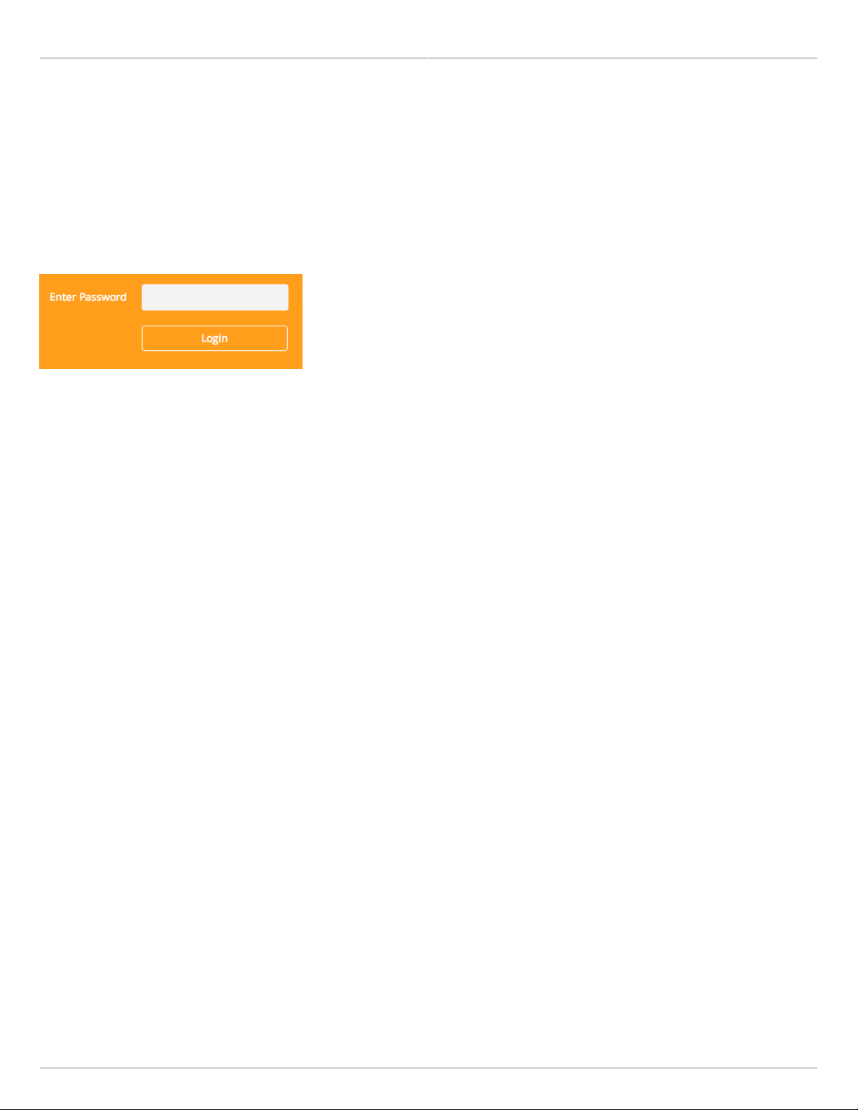
Logging In
After connecting via one of the three access methods, the GUI will prompt you to log-in with a password. The
default password is "mimosa", and should be changed immediately after login to protect your network since it gives
the user read / write privileges. The password can be changed within the Preferences > General > Set Password
panel of the GUI.
Copyright © 2018 Mimosa Page Page 10
Mimosa Backhaul and B24 Help Content
Mimosa Backhaul Overview
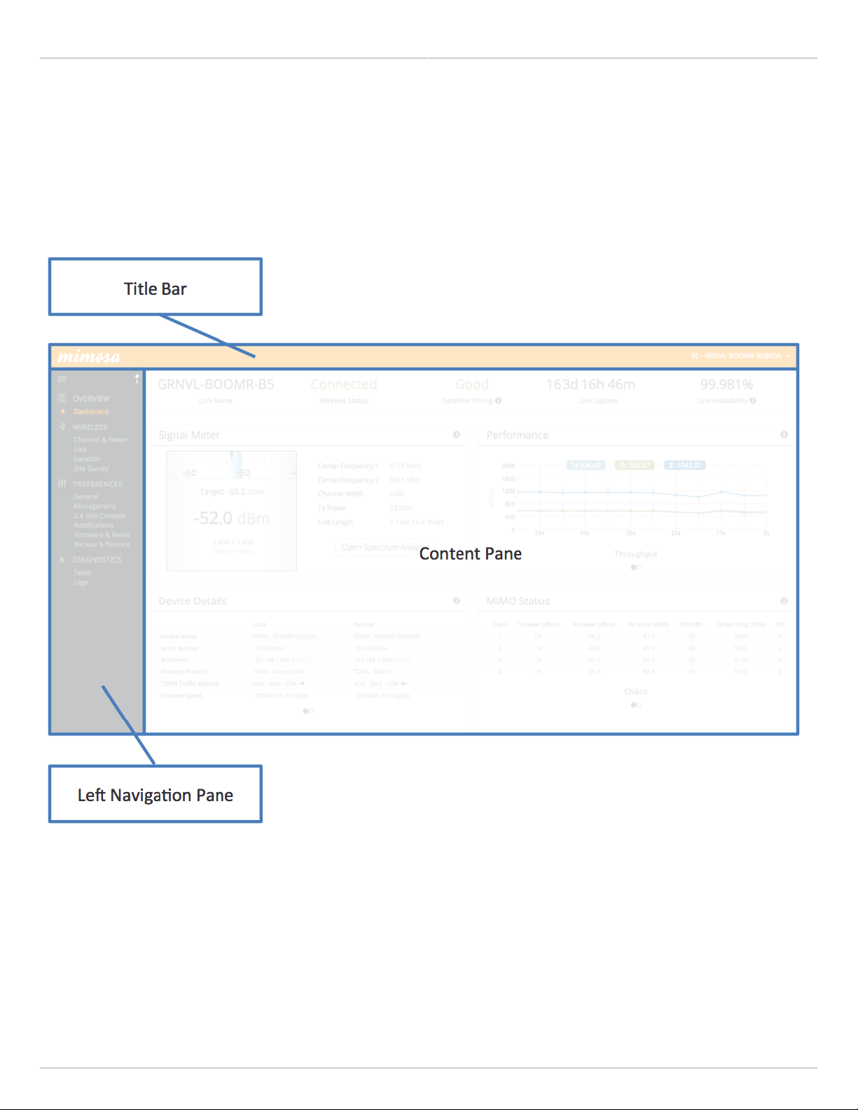
User Interface Overview
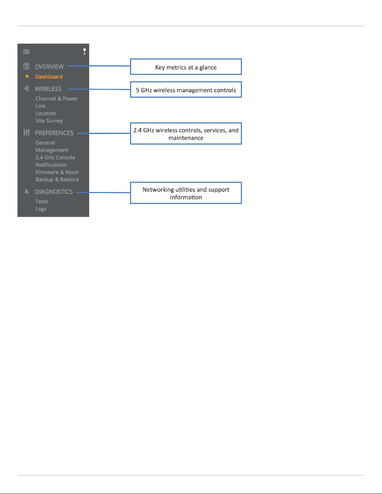
When you first log in, you’ll notice that there is a title bar with the device name shown in the top-right corner, a
navigation pane on the left, and a large content pane on the right. The default page shown in the content pane is
the Dashboard, which shows a summary of overall performance at a glance, and highlights both radio and link
parameters that affect link health.
On the left navigation pane, there are four prominent sections: Overview, Wireless, Preferences, and Diagnostics.
Each of these sections contains one or more links to pages containing task-related data, controls, and tools used to
administer the radio…and you can return the Dashboard at any time by clicking on the Dashboard link in the
Overview section.
The pin in the top corner of the left navigation pane allows you to "pin" open the navigation menu for easier access.
Else, the menu contracts to provide more workspace within the GUI. Note that the 2.4 GHz Console menu item is not
present on the B5-Lite.
Copyright © 2018 Mimosa Page Page 11
Mimosa Backhaul and B24 Help Content
Mimosa Backhaul Overview
Copyright © 2018 Mimosa Page Page 12
Mimosa Backhaul and B24 Help Content Mimosa Backhaul Dashboard
The Dashboard
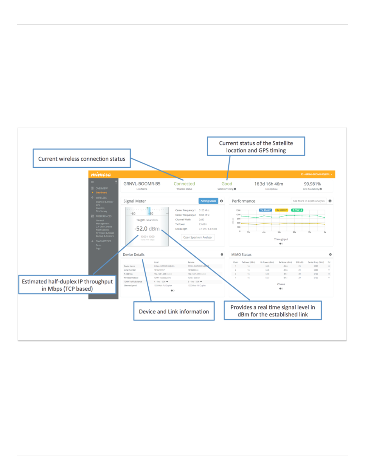
The Dashboard contains several panels used to group related items. The status panel at the top of the page shows
the link SSID, the link status, GPS signal quality*, Link Uptime since association, and Link Availability since the last
reboot. Two of the values on this panel contain an information icon that shows more information when you click or
hover over it with your mouse cursor. On other panels, detailed help text can be found by clicking on the
information icon in the upper right hand corner.
* Applies to B5/B5c, B11, and B24 only; does not apply to B5-Lite or C5c PTP.
Copyright © 2018 Mimosa Page Page 13

Mimosa Backhaul and B24 Help Content
Mimosa Backhaul Dashboard
Reading the Signal Meter
Connected Link
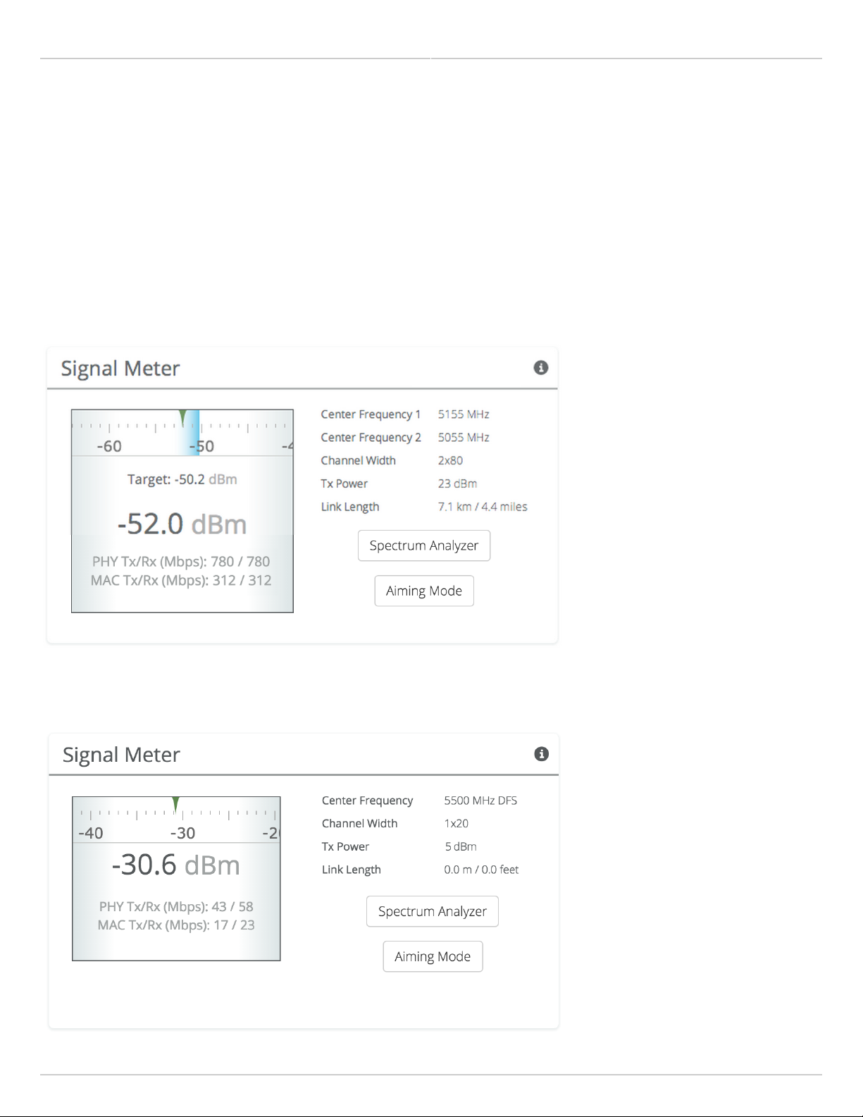
Received signal strength is shown in large text in the center of the control, and as a green indicator in the top dial.
The blue shaded bar and text immediately below the dial represent target signal strength based on distance and
other information exchanged between radios. The objective is to align the green indicator with the blue bar as a
guideline during antenna aiming.
The resulting half-duplex PHY rates shown at the bottom of the Signal Meter control are correlated with the MCS,
and represent raw data across the link without protocol overhead. The Max Throughput values include TDMA
window size and MAC layer efficiency.
The following settings and values that affect link health are listed for reference:
B5/B5c
●
Channel 1 Center Frequency - True center of the first frequency range (no offset).
●
Channel 2 Center Frequency - True center of the second frequency range (no offset).
●
Channel Width - Number of channels used (1 or 2), and the width of each channel (20, 40 or 80 MHz).
●
Tx Power - Total transmit power level (dBm).
●
Link Length - Distance between local and remote radios (when connected).
B5-Lite/C5c PTP
●
Center Frequency - True center of the frequency range (no offset).
●
Channel Width - The width of the channel (20, 40 or 80 MHz).
●
Tx Power - Total transmit power level (dBm).
●
Link Length - Distance between local and remote radios (when connected).
B11
●
Center Frequency 1 - True center of the first frequency range (no offset).
●
Center Frequency 2 - True center of the second frequency range (no offset).
●
Channel Width - Number of channels used (1 or 2), and the width of each channel (20, 40 or 80 MHz).
●
Tx Power - Total transmit power level (dBm).
●
Link Length - Distance between local and remote radios (when connected).
B24
●
Center Frequency 1 - True center of the first frequency range (no offset).
●
Center Frequency 2 - True center of the second frequency range (no offset).
●
Channel Width - Number of channels used (1 or 2), and the width of each channel (20, 40 or 80 MHz).
●
Tx Power - Total transmit power level (dBm).
●
Link Length - Distance between local and remote radios (when connected).
Click the Spectrum Analyzer button to access the Spectrum Analyzer, which can also be found on the Channel &
Power page. This will not disturb the link.
Copyright © 2018 Mimosa Page Page 14
Mimosa Backhaul and B24 Help Content
Mimosa Backhaul Dashboard
When a link is not associated, the signal strength and PHY rates are replaced by an indicator of "Disconnected".
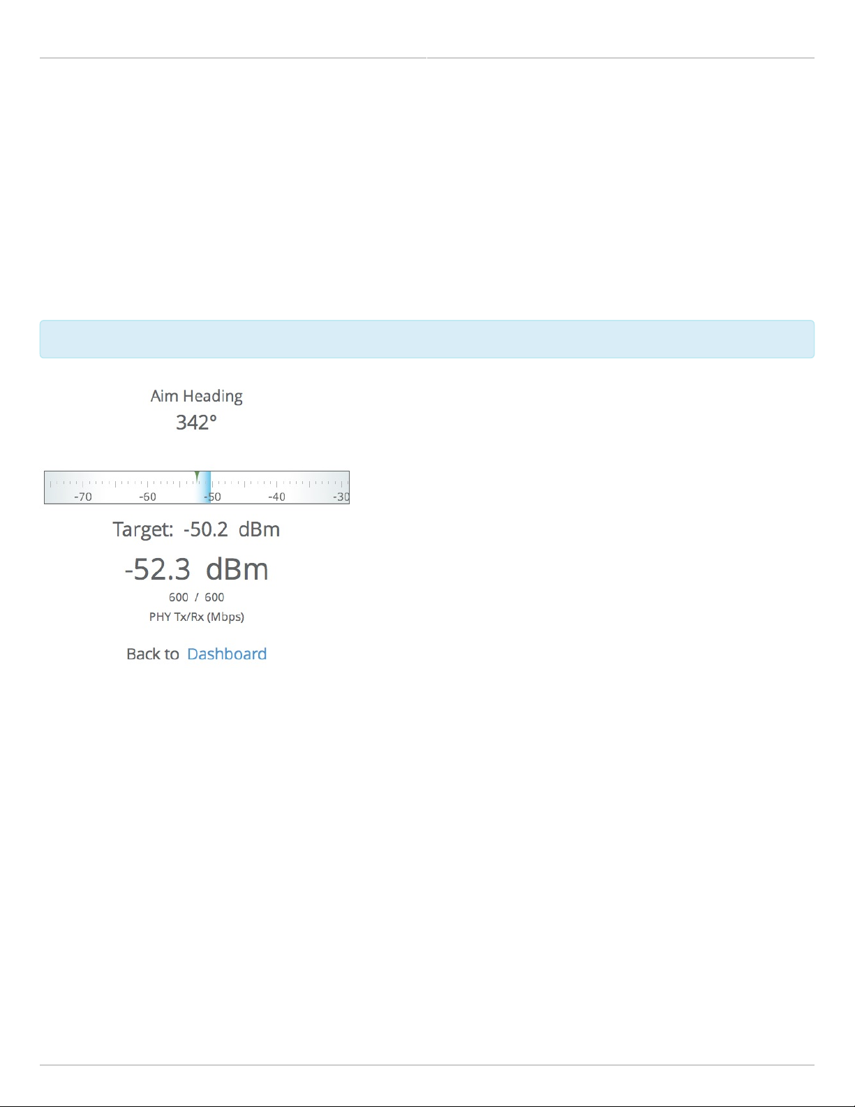
Once associated, click the Aiming Mode button on the Dashboard to open a new window that refreshes once per
second for a 5-minute period. The Aim Heading indicates the direction in which the front of the device should be
pointed based exchange of coordinates. The green arrow and blue shaded region on the dial indicator represent
current and target signal levels, respectively. Note that the dial indicator does not represent azimuth. Azimuth may
need to be adjusted in either direction to meet the target.
B5/B5c Signal Meter
B5-Lite Signal Meter
Copyright © 2018 Mimosa Page Page 15
Mimosa Backhaul and B24 Help Content
Mimosa Backhaul Dashboard
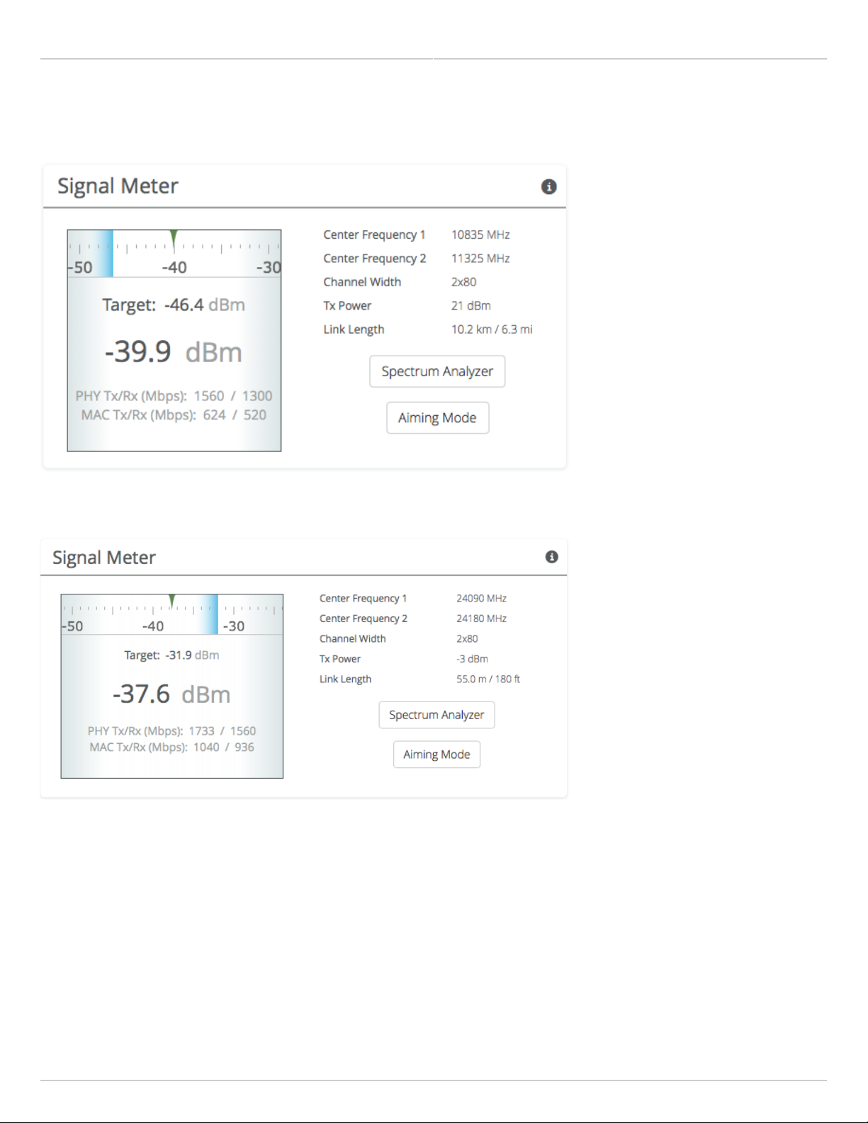
B11 Signal Meter
B24 Signal Meter
Copyright © 2018 Mimosa Page Page 16
Mimosa Backhaul and B24 Help Content
Mimosa Backhaul Dashboard
Antenna Aiming Mode
Product Availibility: B5/B5c, B11, B24
Once associated, click the Aiming Mode button on the Dashboard to open a new window that refreshes once per
second for a 5-minute period. The Aim Heading indicates the direction in which the front of the device should be
pointed based exchange of coordinates. The green arrow and blue shaded region on the dial indicator represent
current and target signal levels, respectively. Note that the dial indicator does not represent azimuth. Azimuth may
need to be adjusted in either direction to meet the target.
Note that the target signal level will be incorrect if the antenna gain value is inaccurate (B5c and B11).
Note that the target signal level will be incorrect if the antenna gain value is inaccurate (B5c and B11).
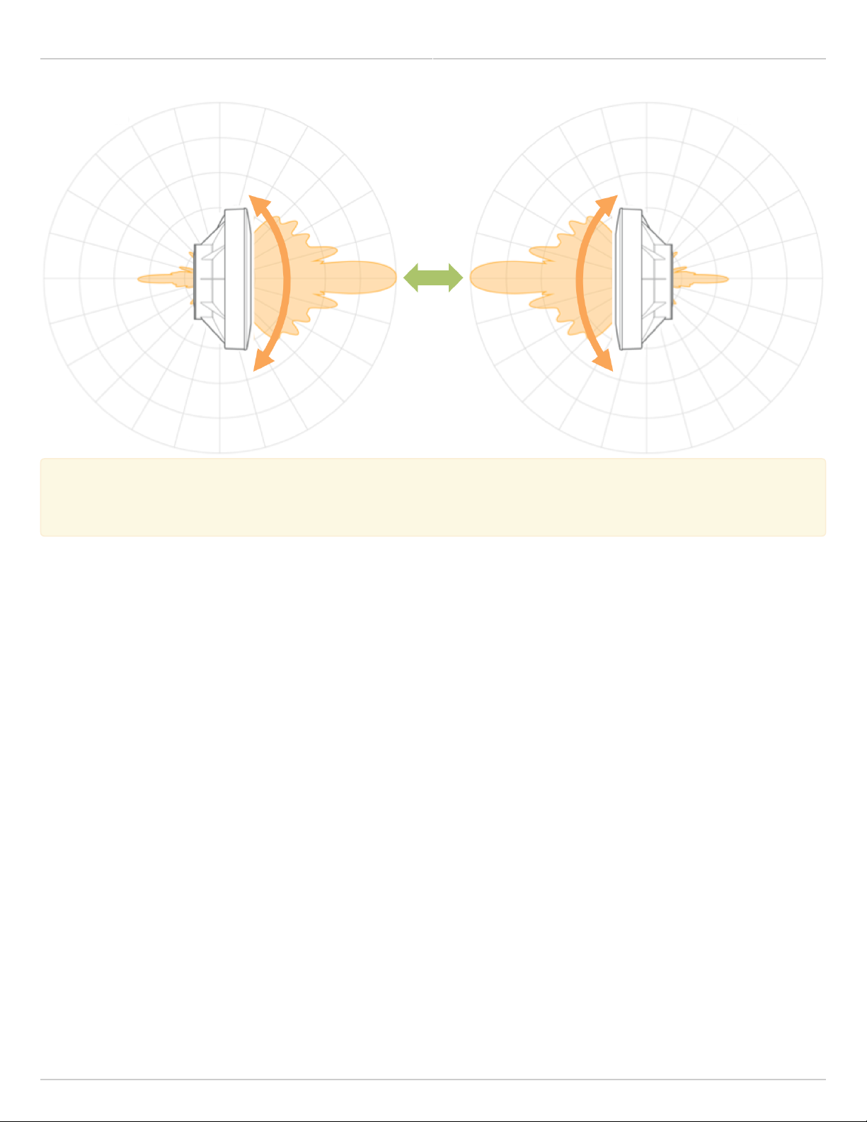
Antenna Aiming Procedure
While viewing the Aiming Mode screen, move the local antenna on one axis at a time (first azimuth and then1.
elevation) in 6mm (1/4 inch) increments.
Wait 2-3 seconds for the signal to settle after each movement. Signal strength may increase or decrease after2.
each movement. Increases in signal strength will move the green arrow and blue shaded region closer
together. Decreases in signal strength will move them farther apart. The point of maximum signal strength
indicates optimal antenna alignment for each axis.
Repeat the steps 1 and 2 above on the remote antenna. The signal strength should match the outputs from3.
the Mimosa Design application. If not, please consult the Low Rx Power troubleshooting guide.
Copyright © 2018 Mimosa Page Page 17
Mimosa Backhaul and B24 Help Content
Mimosa Backhaul Dashboard
Tip: Use a pen (or a piece of tape) to place an alignment mark on both the antenna mount and the
Tip: Use a pen (or a piece of tape) to place an alignment mark on both the antenna mount and the
mounting pole. The gap between the marks will serve as a visual aid to show how far the antenna has
mounting pole. The gap between the marks will serve as a visual aid to show how far the antenna has
turned in either direction.
turned in either direction.
Copyright © 2018 Mimosa Page Page 18
Mimosa Backhaul and B24 Help Content
Mimosa Backhaul Dashboard
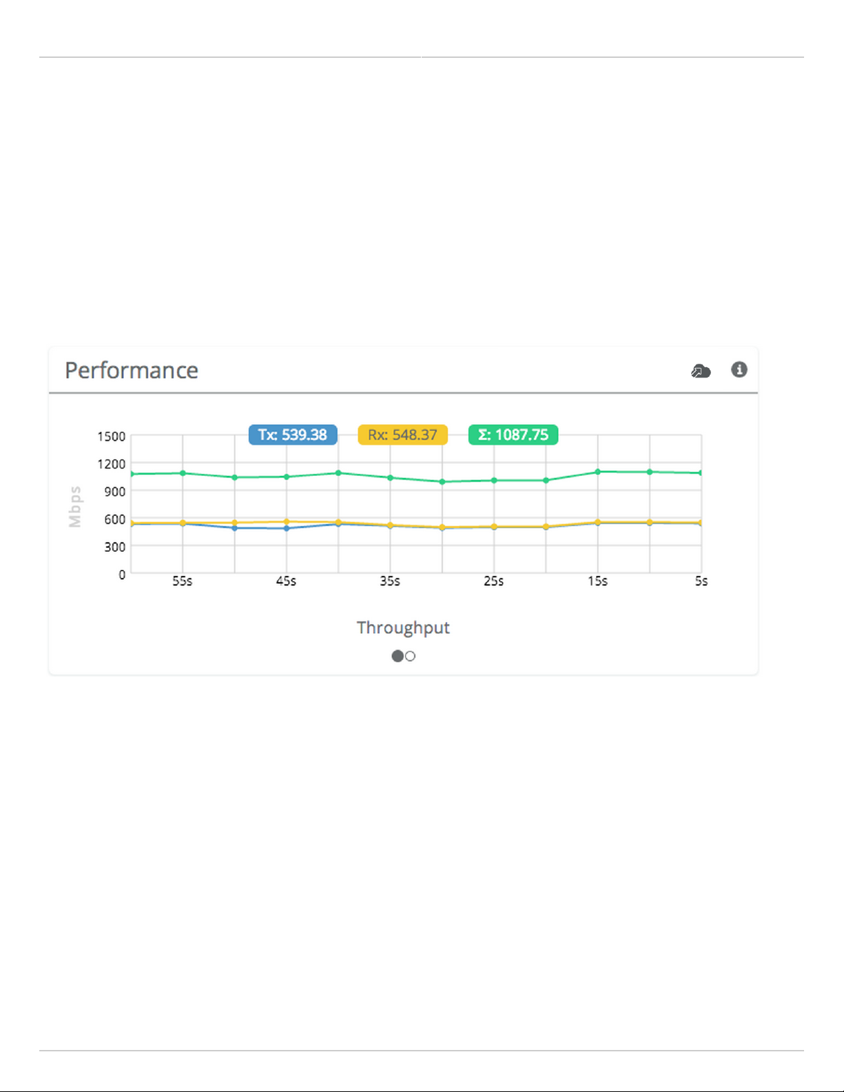
Reading the Performance Charts
IP Throughput and Packet Error Rate (PER) are charted over 60 seconds in 5-second intervals. The newest data
shows up on the right and scrolls to the left over time. You can toggle between the charts by clicking on the
navigation circles at the bottom of the panel. If enabled, click on the cloud icon to view historical data within the
Manage application.
The IP Throughput graph plots three lines representing transmit, receive, and aggregate (summed) throughputs at
the datagram (or packet) layer excluding any protocol or encapsulation overhead. The results here may differ from
those measured using speed test tools, due to protocol overhead and encapsulation. Note that internal Bandwidth
test results are excluded.
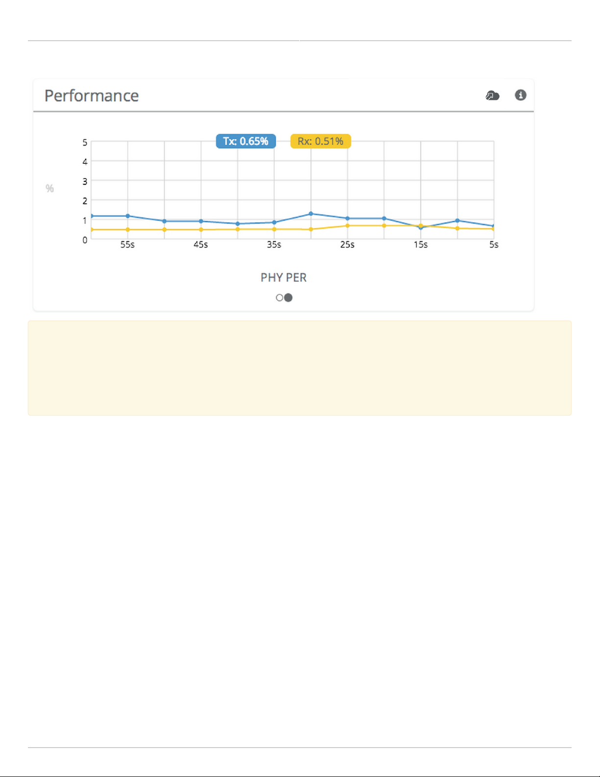
The Packet Error Rate (PER) is the number of packets with errors divided by the total number of packets sent within
a 5-second period. Ideally, this value should be below 2%, while higher values indicate the presence of interference.
Tx PER is an indication that the local radio did not receive an ACK from the remote radio, so is forced to retransmit
the same information again. Rx PER is a value sent from the remote radio to the local radio in management frames.
Copyright © 2018 Mimosa Page Page 19
Mimosa Backhaul and B24 Help Content
Mimosa Backhaul Dashboard
Note: PER will be higher upon initial association, and will usually settle within 30-60 seconds. This is
Note: PER will be higher upon initial association, and will usually settle within 30-60 seconds. This is
because association requires that the radios “listen” more carefully for their link partner until they are
because association requires that the radios “listen” more carefully for their link partner until they are
linked, and this listening period is subject to more interference until Automatic Gain Control (AGC) and
linked, and this listening period is subject to more interference until Automatic Gain Control (AGC) and
Rate Adaptation (RA) adjust parameters to accommodate the conditions. PER values are exchanged
Rate Adaptation (RA) adjust parameters to accommodate the conditions. PER values are exchanged
between radios asynchronously, so the values may not match exactly when referencing both radios at the
between radios asynchronously, so the values may not match exactly when referencing both radios at the
same time.
same time.
Copyright © 2018 Mimosa Page Page 20

Mimosa Backhaul and B24 Help Content
Mimosa Backhaul Dashboard
Reading Device Details
The Device Details panel shows two summary tables for the local and remote device configurations and their status.
Click on the navigation circles at the bottom of the panel to toggle between the two tables.
The table shows the following for both Local and Remote devices:
B5/B5c
●
Device Name - The friendly name given to each device. (Set in Preferences > General > Naming)
●
Serial Number - The unique identifier for the device assigned at the factory.
●
IP Address - The IP address of each device and how it was assigned. (Set in Preferences > Management)
●
Wireless Protocol - The MAC level protocol. (Set in Wireless > Link > MAC Configuration)
●
TDMA Traffic Balance - Identifies the "gender" of the radio, the duration for each TDMA time slot, and ratio of
bandwidth allocated for transmission. (Set in Wireless > Link > MAC Configuration)
●
Ethernet Speed - Data rate and duplex mode of the wired Ethernet interface.
●
Firmware - The latest firmware version applied to each device. (Set in Preferences > Update & Reboot)
●
Internal Temp - Temperature inside the device case (operating range: -40 °C to +60 °C).
●
2.4 GHz MAC - The unique identifier for the 2.4 GHz radio.
●
5 GHz MAC - The unique identifier for the 5 GHz radio.
●
Ethernet MAC - The unique identifier for the physical Ethernet interface.
●
Last Reboot - The date and time at which each device last rebooted.
B5-Lite/C5c PTP
●
Device Name - The friendly name given to each device. (Set in Preferences > General > Naming)
●
Serial Number - The unique identifier for the device assigned at the factory.
●
IP Address - The IP address of each device and how it was assigned. (Set in Preferences > Management)
●
Wireless Protocol - The MAC level protocol. (Set in Wireless > Link > MAC Configuration)
●
TDMA Traffic Balance - Identifies the "gender" of the radio, the duration for each TDMA time slot, and ratio of
bandwidth allocated for transmission. (Set in Wireless > Link > MAC Configuration)
●
Ethernet Speed - Data rate and duplex mode of the wired Ethernet interface.
●
Firmware - The latest firmware version applied to each device. (Set in Preferences > Update & Reboot)
●
CPU Temp - Temperature on the device CPU (operating range: -40 °C to +110 °C).
●
5 GHz MAC - The unique identifier for the 5 GHz radio.
●
Ethernet MAC - The unique identifier for the physical Ethernet interface.
●
Last Reboot - The date and time at which each device last rebooted.
B11
●
Device Name - The friendly name given to each device. (Set in Preferences > General > Naming)
●
Serial Number - The unique identifier for the device assigned at the factory.
●
IP Address - The IP address of each device and how it was assigned. (Set in Preferences > Management)
●
Wireless Protocol - The MAC level protocol. (Set in Wireless > Link > MAC Configuration)
●
TDMA Traffic Balance - Identifies the "gender" of the radio, the duration for each TDMA time slot, and ratio of
bandwidth allocated for transmission. (Set in Wireless > Link > MAC Configuration)
●
Ethernet Speed - Shows data rate and duplex mode if the link is up else "Link Down". Shows "Off" if the
interface is not enabled.
Copyright © 2018 Mimosa Page Page 21
 Loading...