

Page 1

Mimosa Backhaul
copyright © Mimosa. All rights reserved.
http://ap.help.mimosa.co/
The information contained in this document is subject to change without notice.
This document contains proprietary information which is protected by copyright.
All rights are reserved. No part of this document may be photocopied, reproduced,
or translated to another language without the prior written consent of Mimosa.
Page 2

Mimosa Backhaul Help Content
Mimosa Backhaul White Papers & Application Notes
Table of Contents
FAQ's 1 ..........................................................................................................................................................
Backhaul FAQ Overview 1 ......................................................................................................................
Setup 2 ...................................................................................................................................................
Default IP Address 2 ........................................................................................................................
Reset Process 4 ...............................................................................................................................
Reset B5/B5c and B11 4 ...........................................................................................................
Reset B5-Lite 5 .........................................................................................................................
Serial Number Location 7 .........................................................................................................
Unlock Process 11 ...........................................................................................................................
Change Unlock Country 11 .......................................................................................................
No CLI 15 .........................................................................................................................................
Performance 16 ......................................................................................................................................
MAC Throughput 16 .........................................................................................................................
Maximum Tx Power 18 ....................................................................................................................
Maximum Tx Power Details 20 .................................................................................................
Tx Power Optimization 22 ................................................................................................................
SNR Required for each MCS 24 .......................................................................................................
Error Vector Magnitude (EVM) 25 ....................................................................................................
Quality of Service (QoS) 26 .............................................................................................................
Calculating Link Latency 28 .............................................................................................................
Calculating TCP Performance 29 .....................................................................................................
Maximum Link Distance 31 .............................................................................................................
Spectrum Analysis 32 ......................................................................................................................
Auto Everything 33 ..........................................................................................................................
Dual Link 35 ....................................................................................................................................
Collocation 36 .........................................................................................................................................
GPS and Collocation 36 ...................................................................................................................
Relay Site Connections 38 ...............................................................................................................
Compatibility 39 .....................................................................................................................................
Radio Compatibility 39 ....................................................................................................................
Antennas & Coaxial Cables 40 .........................................................................................................
B5c Compatibility 40 ................................................................................................................
B11 Compatibility 42 ................................................................................................................
Traffic Handling 43 ..........................................................................................................................
VLAN Support 44 .............................................................................................................................
Paint 45 ...........................................................................................................................................
Specifications 46 ....................................................................................................................................
Supported Frequencies 46 ...............................................................................................................
Supported Channel Widths 47 .........................................................................................................
Frequency Tolerance 48 ..................................................................................................................
Receiver Sensitivity 49 ....................................................................................................................
4.9 GHz Operation 50 ......................................................................................................................
Power over Ethernet (PoE) 51 ..........................................................................................................
Copyright © 2014 Mimosa Page
Page 3

Mimosa Backhaul Help Content
Mimosa Backhaul White Papers & Application Notes
Hardware & Materials 53 .................................................................................................................
Installation Guide 55 .....................................................................................................................................
Installation Overview 55 .........................................................................................................................
Unlock 56 ...............................................................................................................................................
Radio Unlock Process 56 .................................................................................................................
SMS Verification 58 .........................................................................................................................
Mounting & Grounding 60 ......................................................................................................................
B5 Mounting and Grounding 60 .......................................................................................................
B5c Mounting and Grounding 63 .....................................................................................................
B5-Lite Mounting and Grounding 65 ................................................................................................
B11 Mounting and Grounding 69 .....................................................................................................
Power & Data Connections 70 ................................................................................................................
Power over Ethernet (PoE) 70 ..........................................................................................................
Ethernet Port & IP67 Gland 72 .........................................................................................................
Fiber Port & IP67 Gland 77 ..............................................................................................................
Antenna Connections 79 ........................................................................................................................
B5c Antenna Connections 79 ..........................................................................................................
Backhaul Setup 82 .................................................................................................................................
Backhaul Setup 82 ..........................................................................................................................
Indoor Test Methods 84 ...................................................................................................................
Backhaul RF Tuning Process 86 .......................................................................................................
Installation Videos 88 .............................................................................................................................
B5/B5c Videos 88 ............................................................................................................................
B5-Lite Videos 89 ............................................................................................................................
User Guide 90 ................................................................................................................................................
Overview 90 ...........................................................................................................................................
Accessing the Interface 90 ..............................................................................................................
Logging In 91 ...................................................................................................................................
User Interface Overview 92 .............................................................................................................
Dashboard 94 .........................................................................................................................................
Single Client (PTP) Mode 94 .............................................................................................................
Dashboard Overview 94 ...........................................................................................................
Signal Meter 95 ........................................................................................................................
Aiming Mode 98 ........................................................................................................................
Performance 100 ......................................................................................................................
Device Details 102 ...................................................................................................................
MIMO Status 104 ......................................................................................................................
Multi Client (PTMP) Mode 107 ..........................................................................................................
Dashboard Overview 107 .........................................................................................................
Current Usage 108 ...................................................................................................................
Performance 109 ......................................................................................................................
Client List 110 ..........................................................................................................................
Device Details 111 ...................................................................................................................
Wireless 112 ...........................................................................................................................................
Channel & Power 112 ......................................................................................................................
Spectrum Analyzer 112 ............................................................................................................
Copyright © 2014 Mimosa Page
Page 4

Mimosa Backhaul Help Content
Mimosa Backhaul White Papers & Application Notes
Channel & Power Settings 113 .................................................................................................
Exclusions & Restrictions 117 ...................................................................................................
Link 118 ...........................................................................................................................................
TDMA Configuration 118 ...........................................................................................................
Link Configuration 120 .............................................................................................................
Clients 122 ......................................................................................................................................
Client List 122 ..........................................................................................................................
Location 123 ....................................................................................................................................
Local Satellite Signals 123 ........................................................................................................
Satellite Information 124 ..........................................................................................................
Location Data 125 ....................................................................................................................
Local Coordinates 126 ..............................................................................................................
Remote Coordinates 127 ..........................................................................................................
Distance 128 ............................................................................................................................
Site Survey 129 ...............................................................................................................................
Survey Results 129 ...................................................................................................................
Preferences 130 .....................................................................................................................................
General 130 .....................................................................................................................................
Naming 130 ..............................................................................................................................
Time 131 ..................................................................................................................................
Set Password 132 .....................................................................................................................
Miscellaneous 133 ....................................................................................................................
Management 134 ............................................................................................................................
Management IP 134 .................................................................................................................
Watchdog 135 ..........................................................................................................................
Services 136 .............................................................................................................................
Miscellaneous 137 ....................................................................................................................
Network Interfaces 139 ............................................................................................................
Management VLAN 140 ............................................................................................................
REST Services 141 ....................................................................................................................
2.4 GHz Console 142 .......................................................................................................................
2.4 GHz Network 142 ...............................................................................................................
2.4 GHz Security 143 ................................................................................................................
Notifications 144 .............................................................................................................................
SNMP Notifications 144 ............................................................................................................
SNMP Traps 145 .......................................................................................................................
System Log Notifications 147 ...................................................................................................
System Log Traps 148 ..............................................................................................................
Firmware & Reset 149 .....................................................................................................................
Firmware Update 149 ...............................................................................................................
Reset & Reboot 150 .................................................................................................................
Backup & Restore 151 .....................................................................................................................
Backup & Restore 151 ..............................................................................................................
Diagnostics 152 ......................................................................................................................................
Tests 152 .........................................................................................................................................
Test Overview 152 ...................................................................................................................
Copyright © 2014 Mimosa Page
Page 5

Mimosa Backhaul Help Content
Mimosa Backhaul White Papers & Application Notes
Ping 153 ...................................................................................................................................
Bandwidth 154 .........................................................................................................................
Traceroute 155 .........................................................................................................................
Logs 156 ..........................................................................................................................................
Log Overview 156 .....................................................................................................................
REST API 157 ..........................................................................................................................................
REST API Overview 157 ...................................................................................................................
GET Device Status 158 ....................................................................................................................
GET Device Info 161 ........................................................................................................................
GET Ethernet Configuration 164 ......................................................................................................
GET Link Info 167 ............................................................................................................................
GET Device Reboot 169 ...................................................................................................................
SNMP Interface 170 ................................................................................................................................
SNMP MIB Downloads 170 ...............................................................................................................
SNMP OID Reference Tables 171 .....................................................................................................
SNMP Usage Examples 182 .............................................................................................................
SNMP Get 182 ..........................................................................................................................
SNMP Walk 183 ........................................................................................................................
SNMP Table 184 .......................................................................................................................
SNMP Object Names 185 ..........................................................................................................
Troubleshooting Guide 187 ...........................................................................................................................
Overview 187 .........................................................................................................................................
LED Status Indicators 188 ......................................................................................................................
B5/B5c LED Status 188 ....................................................................................................................
B5-Lite LED Status 191 ....................................................................................................................
B11 LED Status Indicators 192 ........................................................................................................
Ethernet Speed 195 ................................................................................................................................
VLAN Connections 198 ...........................................................................................................................
Intermittent Access 199 .........................................................................................................................
Radios not associated 200 ......................................................................................................................
GPS Signals 202 .....................................................................................................................................
Low SNR 203 ..........................................................................................................................................
High PER 204 ..........................................................................................................................................
Low Rx Power 205 ..................................................................................................................................
Low TCP Throughput 207 .......................................................................................................................
Throughput Testing 208 .........................................................................................................................
Testing Throughput with iPerf 208 ..................................................................................................
Firmware 209 ................................................................................................................................................
Backhaul Firmware Roadmap 209 ..........................................................................................................
B5/B5c 210 .............................................................................................................................................
B5/B5c Firmware Downloads 210 ....................................................................................................
B5/B5c Release Notes 211 ..............................................................................................................
B5-Lite 218 .............................................................................................................................................
B5-Lite Firmware Downloads 218 ....................................................................................................
B5-Lite Release Notes 219 ..............................................................................................................
B11 224 ..................................................................................................................................................
Copyright © 2014 Mimosa Page
Page 6

Mimosa Backhaul Help Content
Mimosa Backhaul White Papers & Application Notes
B11 Firmware Downloads 224 .........................................................................................................
B11 Release Notes 225 ...................................................................................................................
White Papers & Application Notes 228 ..........................................................................................................
Using TDMA-FD 228 ................................................................................................................................
Fresnel Zones 231 ..................................................................................................................................
Copyright © 2014 Mimosa Page
Page 7

Mimosa Backhaul Help Content
Mimosa Backhaul FAQ's
Backhaul FAQ Overview
We categorized our FAQ's to make it easy to find answers. If you didn't find what you were looking for, please let us
know.
FAQ's
Setup
●
Default IP Address
●
Unlock Process
●
Change Unlock Country
Reset
●
Reset B5/B5c
●
Reset B5-Lite
●
Serial Number Locations
Performance
●
MAC Throughput
●
Maximum Tx Power
●
Tx Power Optimization
●
SNR Required for each MCS
●
Error Vector Magnitude (EVM)
●
Quality of Service (QoS)
●
Calculating Link Latency
●
Calculating TCP Performance
●
Maximum Link Distance
●
Spectrum Analyzer
●
Auto Everything
Collocation
●
GPS and Collocation
●
Relay Site Connections
Compatibility
●
Radio Compatibility
●
Traffic Handling
●
VLAN Support
●
Antennas and Coaxial Cables
●
Paint
Specifications
●
Supported Frequencies
●
Supported Channel Widths
●
Receiver Sensitivity
●
4.9 GHz Operation
●
Power over Ethernet (PoE)
●
Hardware & Materials
Monitoring
●
Cloud Connectivity Requirements
Copyright © 2014 Mimosa Page 1
Page 8
Mimosa Backhaul Help Content Mimosa Backhaul Setup
Default IP Address
Mimosa backhaul radios can be accessed either via the wired interface or the 2.4 GHz wireless interface (if
applicable). An internal bridge connects the two interfaces. Each interface is assigned a default IP address (see table
below), and both addresses respond via either interface. The wired interface can either be set manually to a static
IP or changed dynamically via DHCP. The wireless interface IP can not be changed.
Notes:
Notes:
1. The wired Ethernet interface is configured by default to use DHCP with a static failover to the IP address
1. The wired Ethernet interface is configured by default to use DHCP with a static failover to the IP address
in the table below.
in the table below.
2. If applying power to the radio without populating the PoE Data port, the recovery page will be shown via
2. If applying power to the radio without populating the PoE Data port, the recovery page will be shown via
the wireless interface for 5 minutes. This behavior is normal and is a part of the Reset process. In this
the wireless interface for 5 minutes. This behavior is normal and is a part of the Reset process. In this
case, the default wireless IP will be 192.168.26.1.
case, the default wireless IP will be 192.168.26.1.
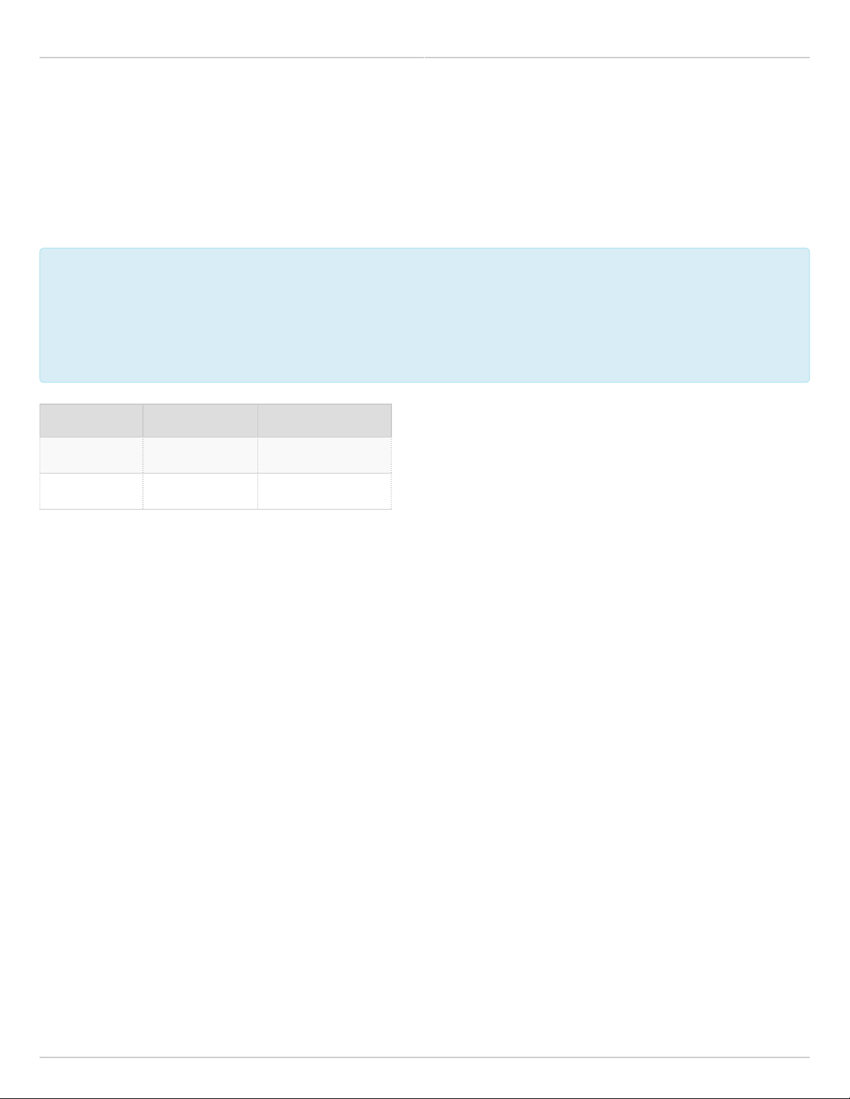
Value Wired Ethernet 2.4 GHz Wireless*
IP Address 192.168.1.20 192.168.25.1
Subnet Mask 255.255.255.0 255.255.255.0
* Does not apply to B5-Lite.
IP Address Discovery
Run the following command from the command line to discover the IP addresses of any directly connected Mimosa
devices. The string "20:B5:C6" is an Organizationally Unique Identifier (OUI), which is the first half of the MAC
address assigned to Mimosa devices. After executing the command, the IP address will be shown for each device.
Windows / DOS:
arp -a | findstr 20:B5:C6
Mac / Linux:
arp -a | grep 20:B5:C6
Port Scan
Run the following command from the command line to discover the port of any directly connected Mimosa devices.
This is especially useful if the port has been changed, and you do not remember the port number.
nmap 192.168.1.20
Copyright © 2014 Mimosa Page 2
Page 9

Mimosa Backhaul Help Content
Mimosa Backhaul Setup
No CDP / LLDP Support
Mimosa radios do not respond to either CDP or LLDP at this time.
Related:
Backhaul Setup Overview - Detailed process for configuring your device
Accessing the Mimosa Cloud - Firewall adjustments for cloud monitoring (no NAT required)
Reset Process - Explains how to recover/reset a device if needed
Copyright © 2014 Mimosa Page 3
Page 10

Mimosa Backhaul Help Content Mimosa Backhaul Reset Process
Reset B5/B5c and B11
Product Applicability: B5/B5c, B11
This process is to restore the device to the factory state when the device is physically available. It replaces
This process is to restore the device to the factory state when the device is physically available. It replaces
a physical reset button and allows recovery without the need to climb a tower.
a physical reset button and allows recovery without the need to climb a tower.
Follow these steps to reset the radio:
Unplug both Ethernet cables from the POE. Leave unplugged for about 3 seconds.1.
Plug in only the data + power cable to the radio. Do not plug in the LAN cable.2.
Immediately connect to the "mimosaR###" SSID (where ### = the last three digits of the serial number)3.
with a PC or mobile device. The SSID and total recovery window expires after 5 minutes.
With a web browser, navigate to 192.168.26.14.
Enter the device serial number located on back of device and click enter.5.
Click the reset button to factory reset the device. This action will remove all configuration settings and6.
passwords.
The radio will then reboot for about 90 seconds.7.
After factory reset, access the device with the default IP address, then follow the device unlock process again before
reuse.
It is also good practice to create a configuration backup such that it can be restored in the case of lost passwords.
Copyright © 2014 Mimosa Page 4
Page 11

Mimosa Backhaul Help Content
Mimosa Backhaul Reset Process
Local Device Reset
Product Applicability: B5-Lite
This process is to restore the device to the factory state when the device is physically available.
This process is to restore the device to the factory state when the device is physically available.
Follow these steps to reset the radio:
Disconnect the Ethernet cable from the radio.1.
Insert a paper clip into the hole next to the Ethernet port (see image below), and then plug the Ethernet cable2.
back in. The green LED will blink slowly after 2 seconds, and then fast after 4 seconds.
Let go of the reset button when the green LED starts blinking fast.3.
The radio will then reboot for approximately 90 seconds.4.
Connect your computer to the LAN input of the PoE.5.
With a web browser, navigate to 192.168.1.20.6.
Reset Button
Copyright © 2014 Mimosa Page 5
Page 12

Mimosa Backhaul Help Content
Mimosa Backhaul Reset Process
After factory reset, access the device with the default IP address and password, then follow the device unlock
process again before reuse.
It is also good practice to create a configuration backup such that it can be restored in the case of lost passwords.
Copyright © 2014 Mimosa Page 6
Page 13

Mimosa Backhaul Help Content
Mimosa Backhaul Reset Process
Finding the Serial Number
The Mimosa serial number is a 10-digit number used to differentiate radios. This unique number is used as
The Mimosa serial number is a 10-digit number used to differentiate radios. This unique number is used as
part of the unlock process to ensure genuine product assurance.
part of the unlock process to ensure genuine product assurance.
There are two ways to find the Serial number on a Mimosa radio:
On the back of the radio, you can find the serial number next to the QR code (see images below).1.
Within the user interface, you can find the serial number on the Dashboard under Device Details.2.
B5 Serial Number Label
Copyright © 2014 Mimosa Page 7
Page 14

Mimosa Backhaul Help Content
Mimosa Backhaul Reset Process
B5c Serial Number Label
B5-Lite Serial Number Label
Copyright © 2014 Mimosa Page 8
Page 15

Mimosa Backhaul Help Content
Mimosa Backhaul Reset Process
B11 Serial Number Label
Copyright © 2014 Mimosa Page 9
Page 16

Mimosa Backhaul Help Content
Mimosa Backhaul Reset Process
Copyright © 2014 Mimosa Page 10
Page 17

Mimosa Backhaul Help Content Mimosa Backhaul Unlock Process
Changing the Unlock Country
Background
During the unlock process, a country must be selected to obtain an unlock code. The country can be changed later,
but a new unlock code is required to do so. Unlock codes are specific to both the serial number of the device and
the country selected.
Process
This process describes how to obtain an unlock code for another country if the device is moved outside of the
original country, or if licensed mode is used:
Log into manage.mimosa.co1.
Click on your network name in the upper right hand corner.2.
Select Settings > Account.3.
Click on the "Choose a Network" drop-down list and select your network name.4.
Copyright © 2014 Mimosa Page 11
Page 18

Mimosa Backhaul Help Content
Mimosa Backhaul Unlock Process
Click on the Add Country Code to Network button.5.
In the dialog box that opens, select the new country to add.6.
Complete additional contact information.7.
If changing to a country with licensed operation ("[Country Name] Licensed"), agree to the Terms of Use and8.
click Add.
Copyright © 2014 Mimosa Page 12
Page 19

Mimosa Backhaul Help Content
Mimosa Backhaul Unlock Process
Click the "Manage" drop-down box, and select Device Unlock.9.
Choose the new unlock country from the "Country" drop-down list. 10.
Copyright © 2014 Mimosa Page 13
Page 20

Mimosa Backhaul Help Content
Mimosa Backhaul Unlock Process
Enter the device serial number.11.
Once you accept the terms and submit, the new unlock code will be shown.12.
Reset the unlock code and enter the new unlock code to complete the process.13.
Copyright © 2014 Mimosa Page 14
Page 21

Mimosa Backhaul Help Content
Mimosa Backhaul Setup
No Command Line Interface (CLI) Access
There is no user-accessible method for SSH or telnet to Mimosa devices. Mimosa Support is the only party capable
of accessing the shell, and only after installation of an RSA certificate.
Mimosa disables the CLI by default due to security, support, and regulatory compliance concerns:
●
Prevents installation of non-Mimosa operating systems that can lead to unsupported configuration changes especially related to regulatory compliance.
●
Protects devices, and data passing across them, from unauthorized access.
●
Deters counterfeiting and reverse engineering of Mimosa's intellectual property.
Copyright © 2014 Mimosa Page 15
Page 22

Mimosa Backhaul Help Content Mimosa Backhaul Performance
MAC Throughput
MAC throughput is shown on the Dashboard Signal Meter as "MAC Tx/Rx (Mbps)". The acronym MAC is short for
"Media Access Control", which is one of two sub-layers within Layer 2 of the Open Systems Interconnect (OSI)
model. Layer 2 is responsible for forward error correction and management of the channel (e.g. flow control,
collision prevention, and TDMA timing). These functions are necessary for the network to operate properly, but they
add processing overhead which results in lower throughput than at the PHY (Layer 1).
TDMA Settings Affect MAC Throughput
On Mimosa radios, MAC throughput can be adjusted since it is a function of the configurable TDMA settings: TDMA
Traffic Split and TDMA Transmit Window. When using TDMA, a time-based MAC protocol, each radio takes turns
sending and receiving. The time allocated to each side for transmission is controlled with the TDMA Traffic Split. This
value can be set in the device GUI to 50/50, 75/25 or 25/75 (in Auto mode). The Traffic Split slash notation follows
the convention: Local Tx Window / Remote Tx Window. The numbers on either side of the slash ("/"), represent the
Duty Cycle for each side.
MAC efficiency varies with the TDMA Window size (2/4/8 ms). Larger windows allow for a larger ratio of data to the
required overhead that accompanies it. Conversely, smaller windows allow for less data to be transmitted at a time
which is necessary for applications that are sensitive to latency (such as VoIP), but the overhead is the same.
Calculating MAC Throughput Based on PHY Rate
The formulas for determining MAC throughput in either direction are the following:
●
MAC Tx Throughput = Tx PHY rate * Tx MAC Duty Cycle * MAC Efficiency
●
MAC Rx Throughput = Rx PHY rate * Rx MAC Duty Cycle * MAC Efficiency
Where:
Tx/Rx MAC Duty Cycle represents the transmit window (25%, 50%, or 75%) based on TDMA Traffic Split.1.
MAC Efficiency is a function of the TDMA Transmit Window from the table below.2.
Transmit Window MAC Efficiency
8 ms 90 %
4 ms 80 %
2 ms 70 %
Example:
Copyright © 2014 Mimosa Page 16
Page 23

Mimosa Backhaul Help Content
Mimosa Backhaul Performance
Tx MAC Throughput (Mbps) = 1560 * 50% * 80% = 624 Mbps
Rx MAC Throughput (Mbps) = 1300 * 50% * 80% = 520 Mbps
Note: The built-in Bandwidth test on the radio (Diagnostics > Tests > Bandwidth) displays UDP results,
Note: The built-in Bandwidth test on the radio (Diagnostics > Tests > Bandwidth) displays UDP results,
which should closely match the MAC Throughput shown on the Dashboard. The UDP protocol is
which should closely match the MAC Throughput shown on the Dashboard. The UDP protocol is
connection-less and unidirectional, whereas the TCP protocol requires bi-directional communication and
connection-less and unidirectional, whereas the TCP protocol requires bi-directional communication and
acknowledgements (ACK) from the remote host in response to a transmission.
acknowledgements (ACK) from the remote host in response to a transmission.
Related:
Calculating TCP Performance - Understanding and optimizing for TCP traffic
TDMA Configuration - Link Configuration in Backhaul User Guide
Copyright © 2014 Mimosa Page 17
Page 24

Mimosa Backhaul Help Content
Mimosa Backhaul Performance
Backhaul Maximum Tx Power
The maximum transmit power that you can select is limited by product specifications, the number of channels in
use, and maximum EIRP limits.
Maximum Transmitter Power
Mimosa Backhaul radios are capable of transmitting at the power levels in the table below. With the B5 and B5c,
total power can be divided equally (preferred) or unequally (if necessary) between the two channels. Once power is
selected for a particular channel, it is then divided equally between H and V chains.
Maximum Tx Power (dBm)
Product Channels Total Power Per Channel Per Chain
B5/B5c 1
2
FD
B5-Lite 1 23 23 20
B11 1/FD
2
* With the B5/B5c, single channel mode has a 3 dB advantage over dual channel mode. This is because
* With the B5/B5c, single channel mode has a 3 dB advantage over dual channel mode. This is because
two channels (four chains) are combined internally with the same frequency and phase.
two channels (four chains) are combined internally with the same frequency and phase.
30
27
24
27
27
30
24*
24
27
24
27
21
21
24
21
Maximum EIRP Limits (5 GHz)
Local laws may restrict maximum EIRP for certain frequency ranges. The chart below shows restrictions in the
United States.
The equations for calculating the maximum Tx power for each band are the following:
One Channel:
Max Tx Power (dBm) = EIRP limit (dBm) - Antenna Gain (dBi)
Copyright © 2014 Mimosa Page 18
Page 25

Mimosa Backhaul Help Content
Mimosa Backhaul Performance
Two Channels:
Max Tx Power (dBm) = EIRP limit (dBm) - Antenna Gain (dBi) - 3 dBm
Example 1 - B5c, 30 dBi, 2 Channels, U-NII-1:
The limits in the chart above for U-NII-1 are currently 40 dBm. After entering the 30 dBi antenna gain on the B5c, Tx
power will be limited to 7 dBm (40 dBm - 30 dBi - 3 dBm).
Example 2 - B5c, 30 dBi, 1 Channel, U-NII-2:
The limits in the chart above for U-NII-2 are currently 30 dBm. After entering the 30 dBi antenna gain on the B5c, Tx
power will be limited to 0 dBm (30 dBm - 30 dBi).
Related:
Backhaul FAQ: Should Tx Power be set to maximum?
Copyright © 2014 Mimosa Page 19
Page 26

Mimosa Backhaul Help Content
Mimosa Backhaul Maximum Tx Power
Backhaul Maximum Tx Power Details
B5/B5c
1 Channel
Total Power
30 dBm
Channel 1 Channel 2
30 dBm NA
Chain 1 Chain 2 Chain 3 Chain 4
27 dBm 27 dBm NA NA
2 Channels
Total Power
27 dBm
Channel 1 Channel 2
24 dBm 24 dBm
Chain 1 Chain 2 Chain 3 Chain 4
21 dBm 21 dBm 21 dBm 21 dBm
FD Mode
Total Power
24 dBm
Channel 1 Channel 2
24 dBm NA
Chain 1 Chain 2 Chain 3 Chain 4
21 dBm 21 dBm NA NA
B5-Lite
1 Channel
Copyright © 2014 Mimosa Page 20
Page 27

Mimosa Backhaul Help Content
Mimosa Backhaul Maximum Tx Power
Total Power
23 dBm
Channel 1 Channel 2
23 dBm NA
Chain 1 Chain 2 Chain 3 Chain 4
20 dBm 20 dBm NA NA
B11
1 Channel
Total Power
27 dBm
Channel 1 Channel 2
27 dBm NA
Chain 1 Chain 2 Chain 3 Chain 4
24 dBm 24 dBm NA NA
2 Channels
Total Power
27 dBm
Channel 1 Channel 2
24 dBm 24 dBm
Chain 1 Chain 2 Chain 3 Chain 4
21 dBm 21 dBm 21 dBm 21 dBm
Copyright © 2014 Mimosa Page 21
Page 28

Mimosa Backhaul Help Content
Mimosa Backhaul Performance
Backhaul Tx Power Optimization
Should I always choose the maximum Tx Power setting for best performance?
Not necessarily. The answer depends on the maximum achievable signal to noise ratio (SNR) for a given link. You
may see a tooltip on the Channel & Power page to this effect like the one below.
Background
A theoretical amplifier would apply gain (the output to input power ratio) linearly to any input signal. For instance, a
10 dB amplifier should amplify a 0 dBm signal to 10 dBm, a 10 dBm signal to 20 dBm, and so on. However, typical
amplifiers are not perfectly linear for all input power. Above a certain power level, the input signal begins to distort
during amplification (in the Compression Region). A distorted output signal from a transmitter is more difficult for
the receiver to interpret, leading to higher EVM and lower MCS.
Recommendations
If the link is short (high Rx Signal Strength), or if SNR is high, select lower Tx Power to allow the transmitting
amplifier to operate within it's Linear Region and avoid distortion in the Compression Region.
If the link is long (low Rx Signal Strength), or if SNR is low, select higher Tx Power and accept some distortion in
Copyright © 2014 Mimosa Page 22
Page 29

Mimosa Backhaul Help Content
Mimosa Backhaul Performance
favor of higher SNR. This is because SNR at the receiver limits the MCS more than the distortion from the Tx
amplifier.
The table below shows the maximum recommended Tx Power settings for a given SNR to achieve the highest MCS
index. Auto Everything dynamically adjusts Tx Power, or these steps should be followed in manual mode:
Note the lowest SNR on Dashboard > MIMO Status.1.
Find the SNR in the first column of the table below.2.
Set Tx Power to a value in the second or third column, depending on the number of channels used.3.
B5/B5c Power Table
SNR (dB)
1-14 27 30
15-18 26 29
19-24 25 28
25-28 24 27
29-40 23 26
>40 63-SNR* 66-SNR*
* Subtract the SNR found in step 2 above.
Dual-Channel
Tx Power (dBm)
Single-Channel
Tx Power (dBm)
Copyright © 2014 Mimosa Page 23
Page 30

Mimosa Backhaul Help Content
Mimosa Backhaul Performance
SNR Required for Each MCS
The table below shows the SNR required for each MCS index as well as the modulation, coding and data rate per
stream based on channel width in MHz. Note that each channel uses up to two streams.
Examples:
●
2 x 80 MHz channels operating at MCS 8 with 4 streams would yield 1560 Mbps (390 Mbps * 4 streams).
●
1 x 40 MHz channel operating at MCS 6 with 2 streams would yield 270 Mbps (135 Mbps * 2 streams).
Modulation and Coding Scheme (MCS) PHY Data Rate (Mbps/stream)
Index Modulation Coding Required SNR (dB) 20 MHz 40 MHz 80 MHz
0 BPSK 1/2 5 7.2 15 32.5
1 QPSK 1/2 7.5 14.4 30 65
2 QPSK 3/4 10 21.7 45 97.5
3 16-QAM 1/2 12.5 28.9 60 130
4 16-QAM 3/4 15 43.3 90 195
5 64-QAM 2/3 17.5 57.8 120 260
6 64-QAM 3/4 20 65 135 292.5
7 64-QAM 5/6 22.5 72.2 150 325
8 256-QAM 3/4 25 86.7 180 390
9 256-QAM 5/6 27.5 n/a 200 433
Related:
Backhaul FAQ: What is the sensitivity for each MCS index?
Copyright © 2014 Mimosa Page 24
Page 31

Mimosa Backhaul Help Content
Mimosa Backhaul Performance
Error Vector Magnitude (EVM)
The error vector magnitude or EVM describes how well the receiver can detect symbols (data) within a constellation
of symbols on the I-Q plane for a particular modulation. It is the difference in RMS power between the point where a
symbol is received and where the symbol should be. This difference is caused by noise.
When analyzing EVM, the lower the number the better.
EVM (dB) EVM (%) Assessment
0 100.0 Poor
-5 56.2 Poor
-10 31.6 Poor
-15 17.8 OK
-20 10.0 Good
-25 5.6 Good
-30 3.2 Excellent
-35 1.8 Excellent
Copyright © 2014 Mimosa Page 25
Page 32

Mimosa Backhaul Help Content
Mimosa Backhaul Performance
Quality of Service (QoS) Support
Mimosa backhaul radios support four different L2/L3 QoS queues for traffic prioritization. Typically, an upstream
router sets values for CoS (L2), or DSCP/TOS (L3) for specific traffic on the post-routing chain. After packets leave
the router, they enter the radio where the traffic is queued and sent according to the packet marking. While the
radio does not function as a router, it does respect packet markings assigned by the upstream router.
The table below lists the four QoS queues and corresponding prioritization values for various traffic marking
standards.
Traffic Queue
BE 0 0-31 0-7 20
BK 1 32-63 8-15 10
BK 2 64-95 16-23 10
BE 3 96-127 24-31 20
VI 4 128-159 32-39 30
VI 5 160-191 40-47 30
VO 6 192-223 48-55 40
VO 7 224-255 56-63 40
where,
BK = Background (lowest priority)
BE = Best Effort
VI = Video
VO = Voice (highest priority)
IEEE P802.1p
(VLAN CoS Priority)
TOS DSCP
Mimosa Weighting
(% of capacity)
Mimosa QoS Weighting
Mimosa radios dynamically allocate link capacity by expanding or contracting each traffic queue based on the
current mix of marked traffic. If there is no traffic in a particular queue, that capacity is divided between the other
queues according to their relative weights. Unmarked traffic is processed in the Best Effort (BE) queue by default.
Copyright © 2014 Mimosa Page 26
Page 33

Mimosa Backhaul Help Content
Mimosa Backhaul Performance
Copyright © 2014 Mimosa Page 27
Page 34

Mimosa Backhaul Help Content
Mimosa Backhaul Performance
Link Latency
Product Applicability: B5/B5c, B5-Lite
Link latency is the delay between the time a packet enters the local radio and exits the remote radio in one
direction. In many cases, constraining latency across one link (or more) is a requirement for providing services such
as VoIP that are more sensitive to packet arrival times.
Average link latency is configured with the TDMA Window Size. Available options include 2, 4, and 8 ms. Operators
should take into account the total number of hops when setting TDMA Window Size to ensure that total latency
meets requirements.
In practice, the average latency (in the presence of noise and resulting retries) in one direction is 1.25 * the TDMA
Window Size:
1-Way Latency (ms) = 1.25 * TDMA Window Size (2/4/8 ms)
For example, 2 hops (back-to-back links) with a 4 ms TDMA Window would result in 10 ms average latency (2 hops *
4 ms * 1.25 = 10 ms) in one direction.
Latency tests are usually performed from a command line or embedded interface with the ping command, which
returns the round trip time (RTT) across the link and back. The implication is that ping results will be double of the 1-
Way Latency.
Round Trip Time (ms) = 2.5 * TDMA Window Size (2/4/8 ms)
Note that RF interference, and resulting packet errors (indicated as PER on the Dashboard), can lead to retries and
more round-trips to complete a ping.
Asymmetric TDMA Traffic splits (75/25 or 25/75) have a negligible affect on RTT since the total time always adds up
to one full cycle.
Copyright © 2014 Mimosa Page 28
Page 35

Mimosa Backhaul Help Content
Mimosa Backhaul Performance
TCP Performance
Mimosa Backhaul radios are designed to pass many data streams, and although a Mimosa link may have a full
gigabit of capacity, a single TCP stream will not saturate the link. However, multiple TCP streams can saturate the
link, and better represent typical backhaul applications where multiple TCP streams occur asynchronously. This can
be demonstrated by comparing single and multiple streams when testing throughput with iPerf. The reasons for this
difference are described below.
TCP Protocol Background
Transmission Control Protocol (TCP) is a connection-based protocol that requires an acknowledgement for each data
packet sent between hosts to ensure reliable communication. A sender sends a packet to a receiver, and the
receiver sends an acknowledgement back to the sender. If the sender does not receive an acknowledgement, it will
retransmit the original packet.
Each host participating in the TCP connection also has a default TCP Window Size (or TCP Receive Window) which
defines the amount of data that each host can accept without acknowledging the sender. TCP transmits data up to
the TCP Window Size and then waits for an acknowledgement, so the full capacity of the link may not be used.
Factors Affecting TCP Throughput
TCP connections, such as for file transfers and database queries, are affected by these controllable factors:
●
The TCP Window Size can be adjusted manually for each host that participates in the TCP connection. Most
operating systems adjust the TCP Window Size dynamically with maximum send and receive windows that can
be overridden, or with heuristics and scaling algorithms than can be modified or disabled. Consult your
operating system documentation for more information. Throughput test software in routers and in desktop
applications may artificially limit the TCP Window, so be sure to understand what values are applied before
drawing conclusions from the results they provide.
●
Internal and external network latency may also be introduced by other devices such as switches and routers
between each host and the Mimosa Backhaul radios. Test round trip times between devices to determine their
impact on overall latency. Link latency, or round-trip time (RTT), across the Mimosa link can be reduced in the
following ways:
●
Fixed TDMA: Latency can be controlled by selecting an appropriate TDMA Window setting (2/4/8 ms). The
round trip time (RTT) can be calculated as described within the Calculating Link Latency article, and
measured empirically with ping results.
●
Auto TDMA: This mode results in the lowest latency, but it is not compatible with GPS synchronized spectrum
sharing. The transmit window is as long as is necessary (up to 4ms) to send whatever data is available at the
time, and then control is passed back to the other side. Select "Auto" as the gender and traffic split (Wireless
> Link > TDMA Configuration) on the AP to operate in this mode.
●
Latency can also occur if the link is already saturated, and some TCP streams are queued while waiting for
access to the medium. If possible, increase channel width to add capacity, or improve SNR to enable higher
order modulation.
●
The Packet Error Rate (PER) can cause variations in latency because packets received with errors must be
resent from radio to radio at the MAC layer. This latency can cause TCP to reduce the maximum transmit
window, so care should be taken to follow the Backhaul RF Tuning Process to minimize (and stabilize) PER
before attempting throughput tests.
Copyright © 2014 Mimosa Page 29
Page 36

Mimosa Backhaul Help Content
Mimosa Backhaul Performance
●
Packet loss can occur on Ethernet between hosts and Mimosa radios due to cabling or port problems, the
amount of which is detected and reported by most commercial routers. Packet loss can also occur on routers
due to lack of QoS policies, or in the presence of rate-limits that may be applied.
Calculating Maximum TCP Throughput (Single TCP Stream)
This formula can be used to calculate the maximum TCP throughput for a single stream given TCP Window size and
Latency:
TCP Throughput (bps) = TCP Window Size (bits) / Latency (seconds)
Example (64 KB TCP Window Size, 10 ms Latency)
Take the TCP Window Size in KB and convert to bits in Base 2 (binary):1.
64 KB * 1024 bytes/KB * 8 bits/Byte = 524288 bits
Take the latency in milliseconds and convert to seconds:2.
10 ms / 1000 ms/sec = 0.010 sec
Substitute the results from above into the original equation:3.
Throughput (bps) = 524288 bits / 0.010 seconds = 52428800 bps or 52.4 Mbps
Calculating Optimal TCP Window Size
This formula can be used to calculate the optimal TCP Window size if the MAC Throughput and the latency are
known:
TCP Window (KB) = [ MAC Throughput (Mbps) * RTT (ms) ] / 8192 bits/KB
Example (500 Mbps MAC Throughput, 10 ms latency)
(500 Mbps * 10 ms) / 8192 bits/KB = ~610 KB
Calculating Maximum Latency for a Desired Throughput
This formula can be used to calculate the maximum tolerable latency to achieve a desired throughput:
TCP Window Size (bits) / TCP Throughput (bps) = Latency (seconds)
Example (500 Mbps Throughput, 625 KB TCP Window Size)
(625 KB * 8192 bits/KB) / (500 Mbps * 1000000 bits/Mbit) = 0.0102 seconds or 10.2 ms.
Copyright © 2014 Mimosa Page 30
Page 37

Mimosa Backhaul Help Content
Mimosa Backhaul Performance
Backhaul Maximum Operating Distance
The maximum operating distance (or range) you can expect to achieve largely depends on your design
requirements for throughput and reliability. Throughput on longer links is constrained primarily by the physics of
free space path loss (FSPL). The maximum distance and throughput that Mimosa's Backhaul products can achieve
depend on a variety of additional factors, so we suggest modeling your link using our free Design application here
for a specific answer: cloud.mimosa.co
Copyright © 2014 Mimosa Page 31
Page 38

Mimosa Backhaul Help Content
Mimosa Backhaul Performance
Backhaul Spectrum Analyzer
Mimosa backhaul radios continuously scan the entire operating spectrum in a background task without disturbing
the link.
In addition, Mimosa Cloud Services can record historical spectrum analysis for all of your Mimosa devices. The
spectrum data can be visually played back to identify trends and gain insight into how the RF environment impacts
your customers.
Mimosa provides storage of up to 24 hours of spectrum data for all your Mimosa devices as a free service.
Communication between your devices and Mimosa Cloud Services is optional, but you will not be able to gain access
to cloud features such as spectrum playback without Mimosa Cloud Services.
Copyright © 2014 Mimosa Page 32
Page 39

Mimosa Backhaul Help Content
Mimosa Backhaul Performance
Auto Everything
Product Applicability: B5/B5c, B5-Lite
Auto Everything (AE) is a feature that makes automatic adjustments to link settings (channels, channel width,
transmit power, and single or dual channel modes) in response to changes in the RF spectrum with the goal
of achieving balance between link reliability and capacity. The algorithm calculates prospective quality of
available channels, and then ranks each based on the expected achievable link rate at the physical layer (PHY).
Auto Everything comprises the following four sub-processes:
●
INITIAL SETUP - Upon powering the radios, the Access Point (AP) is automatically set to a 1x20 MHz channel and
then attempts to associate with the Station. Upon association, a quick channel analysis is initiated to find the
clearest channels within the available spectrum. The radios are then set to use the best channel(s).
●
HEALTH CHECK - Monitors channel quality in the background frequently (HEALTH CHECK) and changes channels
if the link consistently has a high Packet Error Rate (PER). If the HEALTH CHECK fails, the radio will change to
the next best available channels from the list generated during full analysis.
●
CONSTANT OPTIMIZATION - Changes to better channels (higher PHY rate), when available, even if the current
channels have sufficiently low PER. Optimization often also involves increasing channel width, and/or changing
from single channel to dual channel mode.
●
POWER SELECTION - Calculates and sets optimal transmit power while complying with regulatory restrictions.
Frequency of Channel Changes
●
Interference: If the link experiences high PER consistently for approximately 2 minutes, the Access Point will
select the best alternative channel(s). If link health is still poor after the first change, Auto Everything will
continue to select the next best channel from its spectrum options. It will continue to do this 6 times, for a total
of 12 minutes. If after 12 minutes, it still cannot find a channel with sufficiently low PER, it will revert to INITIAL
SETUP mode and attempt to associated on a clean 1x20 channel.
●
Clearer Channel Identification: Auto Everything strives to keep the radio on the clearest channel or channels.
Auto Everything performs background scans and monitors those channels which have considerably better
conditions than the existing channels in preparation for their need. When channel change is induced due
to finding a clearer channel (and not due to interference), the channel change occurs after ten background
analysis cycles because the change is a non-critical improvement to link health.
Channel Analysis
Auto Everything calculates expected throughput for each channel using spectrum data from both sides of the link.
The AP periodically pulls analysis data from the STATION and selects channels that are clear for both radios. If Auto
Everything is unable to find a mutually clean channel for both sides of a link, it will choose a 1x FD mode. Channel
analysis runs as a background process which constantly updates the list of good channels based on changes in
spectrum.
Adjustment to B5c EIRP
Auto Everything will recalculate the maximum allowed transmit power based upon the antenna gain (B5c only). Any
change to antenna gain (Wireless > Channel & Power > Channel & Power Settings > Antenna Gain) will cause AE to
recalculate the new max allowed transmit power during channel analysis.
Copyright © 2014 Mimosa Page 33
Page 40

Mimosa Backhaul Help Content
Mimosa Backhaul Performance
Turning Off Auto Everything
Auto Everything can be turned off by selecting "Off (Manual)" in the drop-down box. If turned off, Auto
Everything will stop monitoring channel health and will no longer change channels. However, the AE process will
continue performing channel analysis in the background and maintaining a list of best channels for when AE is re-
enabled. Recommendations from this channel analysis are available on the Channel & Power page for manual
selection.
Auto Everything and Excluded Channels
Auto Everything can be prevented from using specific frequency range(s) by adding them to the exclusion list on the
AP (Wireless > Channel & Power > Exclusions & Restrictions), and then saving. The station will inherit the same
exclusions from the AP during association. This will restart the current background channel analysis process and
exclude both the newly added channels and any channels on the existing exclusion list. Auto Everything will also
change the current channels if the new exclusion channels make them invalid. Similarly, removing channels from
the exclusion list will restart the background channel analysis to make use of newly available channels.
Copyright © 2014 Mimosa Page 34
Page 41

Mimosa Backhaul Help Content
Mimosa Backhaul Performance
Dual Link
Product Applicability: B5, B5c, B11
Upon sensing interference on one channel that would cause the entire link to reduce modulation, the Dual Link
feature dynamically routes traffic to the channel with the lower packet error rate (PER) to improve noise immunity
and prevent packet loss.
This is accomplished by turning off the receive chains on the channel that is suffering the most (in two channel
mode). This allows the radio to receive at the highest MCS rate on the channel with lower interference, and the radio
continues to transmit on both channels.
Copyright © 2014 Mimosa Page 35
Page 42

Mimosa Backhaul Help Content Mimosa Backhaul Collocation
Integrated GPS and GLONASS Receiver
Product Applicability: B5/B5c, B11
The B5, B5c and B11 include an integrated receiver that receives signals from both GPS and GLONASS satellites.
This effectively doubles the number of available satellites to obtain a lock over a pure GPS receiver. The receiver is
able to provide accurate latitude and longitude information that you may use in conjunction with Mimosa Cloud
Services to show the position of your devices overlaid on a map for planning and management purposes.
The GPS/GLONASS receiver is also required for timing synchronization to allow TDMA timing slots to operate
correctly between devices. GPS timing alone is not sufficient to achieve this, as over time the accuracy is
compromised and synchronization between devices will drift. To ensure reliable time synchronization, the product
includes a GPS-Disciplined Oscillator (GPS-DO) with 3 ppb (parts per billion), or 40 ns accuracy. This allows devices
to stay synchronized from a timing perspective without requiring any form of communication with nearby radios or
to the cloud. This also means that even if there are multiple users of Mimosa radios in a single site, that these can
also be synchronized for TDMA operation.
Note that the B5-Lite does not include a GPS receiver.
Collocation with Other Radios
Product Applicability: B5/B5c, B11
What are the guidelines for collocation with other Mimosa radios?
Up to four (4) Mimosa B5, B5c or B11 radios are designed work together on the same tower, even on the same
channel(s), because they are synchronized via GPS. We recommend 80-90° angular separation and equal Rx power
per site for maximum performance.
Can I collocate at a site where Mimosa radios are on separate towers?
Yes, all Mimosa radios at the same site (even on separate towers) can be collocated and share frequencies so long
as they are configured with the same TDMA settings.
What are the guidelines for collocation with non-Mimosa radios?
Other non-Mimosa radios on the same tower may not use GPS synchronization in the same way, or at all, so some
general rules of thumb apply. Ensure three meters (or ten feet) of physical separation, greater than 30° angular
separation, and 20-30 MHz of frequency separation depending on the PSD mask of the neighboring radio. The B5's
built-in Spectrum Analyzer can be used to select channels with the lowest amount of noise.
Can Mimosa synchronize with non-Mimosa radios?
No, Mimosa radios do not synchronize with any non-Mimosa radios.
Copyright © 2014 Mimosa Page 36
Page 43

Mimosa Backhaul Help Content
Mimosa Backhaul Collocation
Collocating with another operator
Product Applicability: B5/B5c, B11
As more Mimosa radios are deployed, they will commonly show up in Site Survey results. The TDMA and Collocation
Synchronization White Paper describes how to design your own collocated network with devices that you control,
but it is also possible to collocate with other radios that you do not control by choosing compatible TDMA settings.
Use Site Surveys
Use the Site Survey feature (Wireless > Site Survey) to list Access Points and their TDMA settings. Once you know
the TDMA settings of other local Mimosa radios, you can choose to coordinate by selecting the same Gender, Traffic
Split and TDMA Windows without having to communicate with the other party.
In the example below, the radios that have higher signal strength (-51 and -40) are probably local, and are likely to
cause interference unless you are willing to adjust your TDMA settings to match, or select an entirely different
channel. The radio that has lower signal strength (-79) is probably a remote AP and can be ignored.
Choose Compatible TDMA Settings
Navigate to TDMA Settings (Wireless > Link) on your radio and select the same settings as the other local radios on
the same tower. In the example below, the Gender, Traffic Split and TDMA window were selected for compatibility
with the TDMA settings of the radios in the Site Survey results above.
Related:
TDMA and Collocation Synchronization White Paper - Collocation planning and examples
Copyright © 2014 Mimosa Page 37
Page 44

Mimosa Backhaul Help Content
Mimosa Backhaul Collocation
Backhaul Relay Connection
Two Backhaul radios can be connected back-to-back without a switch or router. This is accomplished by inserting
the same Ethernet cable into the LAN ports of both PoE injectors. The example below shows relay connections:
Radio 1 - PoE 1 - Ethernet Cable - PoE 2 - Radio 2.
There is a small amount of memory within each of the radio's transmit buffer queue. If both radios are receiving at
the same time, they forward packets out to Ethernet, which will go in the other radio's transmit queue. When it
comes time to transmit, data frames are taken from the Ethernet transmit queue, the appropriate wireless
aggregation is applied, and then the packets are sent over-the-air.
Copyright © 2014 Mimosa Page 38
Page 45

Mimosa Backhaul Help Content Mimosa Backhaul Compatibility
Mimosa Backhaul Product Family Compatibility
B5 and B5c
The B5 and B5c are compatible and can be used in a link together. They are built on an identical hardware and
software platform, with the only differences being the physical enclosure, the use of external connectors and the
addition of antenna gain selection in firmware for B5c.
The selection between a B5 and B5c depends on the application. The B5c allows you to leverage an existing dish
installation and may be better for use on longer links. When distance is less of a concern, B5 is recommended due to
smaller footprint and low weight making it simple to install. Mimosa's free Design application can be used to model
the different performance parameters of each product to aid in selection.
B5-Lite
The B5-Lite is not compatible with the B5 or B5c because the B5-Lite does not contain GPS for timing, and has 45
degree dual-slant polarization.
B11
The B11 is compatible with other Mimosa B11 radios only.
Not compatible with other brands
Mimosa radios employ a proprietary protocol and must be used in pairs. They do not operate in a mode that allows
communication with non-Mimosa radios.
Backhaul and Point-to-Multipoint (PTMP)
The B5/B5c, B5-Lite, and B11 are designed to operate exclusively in point-to-point (PTP) links between two devices.
They do not support point-to-multipoint (PTMP) operation.
Copyright © 2014 Mimosa Page 39
Page 46

Mimosa Backhaul Help Content Mimosa Backhaul Antennas & Coaxial Cables
B5c Antenna Compatibility
The B5c has a frequency range of 4900-6000 MHz. Any high-quality antenna optimized for these frequencies will
work.
The Mimosa B5c was designed to achieve the published performance with cross-polar isolation of 20 dB, primarily
because the MIMO processor can discern between signals well at this level. Increasing the cross-polar isolation will
not improve capacity or throughput.
Tip: Some antennas that are rated for “5 GHz” may not cover the entire band. It is common to see
Tip: Some antennas that are rated for “5 GHz” may not cover the entire band. It is common to see
antennas that are specified to work from 5.45 to 5.85 GHz. They may not operate well, or at all, outside of
antennas that are specified to work from 5.45 to 5.85 GHz. They may not operate well, or at all, outside of
their specified range of operation.
their specified range of operation.
Recommended RF Cable for B5c
As a best practice, ensure that cable specifications are available during the design process, and that the total
insertion loss from cable and connectors is included in the link budget.
Mimosa recommends the following specifications for coaxial cables to connect an antenna to the B5c:
●
Double-shielded, 5 GHz-rated, 50-Ohm, Low Loss
●
Outdoor-rated (UV-stabilized)
●
Inner Conductor: solid 2.74 mm (0.108 inch)
●
Dielectric: Foam
●
Length: less than 2 m / 6.6 feet
●
Connectors:
●
Type N Male for connection to B5c
●
Type N Male or RP-SMA Male depending on antenna connector
Please follow the cable manufacturer's recommended bend radius guideline to prevent damage that could lead to
additional loss.
4x4 MIMO with Two Antenna Connectors
The B5/B5c has only two antenna connectors, one for each polarization: horizontal and vertical. The four MIMO
streams are divided both by frequency and polarization. Streams with the same polarization enter an RF combiner
circuit before heading to one of the antenna connectors. The radio at the far end of the link can discern between
frequencies with the same polarization.
Double-slant (45-degree) Antenna Offset
Some users ask if rotating the B5c antenna reduces interference by 3 dB.
In the presence of rain, vertically polarized waves attenuate less than horizontal polarized waves. Rotating the
vertical polarization to be more horizontal would normalize the performance between the two polarizations during
rain events, but it would also result in lower overall performance because of the additional rain fade.
Mimosa has implemented a software Transmit Power Control (TPC) algorithm that attempts to equalize Rx signal
Copyright © 2014 Mimosa Page 40
Page 47

Mimosa Backhaul Help Content
Mimosa Backhaul Antennas & Coaxial Cables
strength across the 4 chains if they are unequal.
For these reasons, Mimosa normally recommends maintaining standard antenna orientation (horizontal polarization
parallel with ground, vertical polarization perpendicular to ground) when using the B5/B5c. This especially applies
to longer backhaul links in areas that experience heavy precipitation.
The B5-Lite uses a 45-degree slant and is meant for shorter range applications.
Copyright © 2014 Mimosa Page 41
Page 48

Mimosa Backhaul Help Content
Mimosa Backhaul Antennas & Coaxial Cables
B11 Antenna Compatibility
The B11 has a frequency range of 10000-11700 MHz. Compatible antennas are listed on the B11 accessories page.
4x4 MIMO with Two Antenna Connectors
The B11 has transmits and receives on two polarizations: horizontal and vertical. The four MIMO streams are divided
both by frequency and polarization. Streams with the same polarization enter an RF combiner circuit before heading
to the antenna feed. The radio at the far end of the link can discern between frequencies with the same
polarization.
Copyright © 2014 Mimosa Page 42
Page 49

Mimosa Backhaul Help Content
Mimosa Backhaul Compatibility
Traffic Handling
Layer 2 Bridge
Mimosa Backhaul products are designed to operate as a Layer 2 transparent bridge (a virtual wire) for maximum
performance. The radios simply pass all traffic, regardless of type. However, they do support traffic prioritization
with four (4) quality of service (QoS) queues.
Multicast
Mimosa Backhaul radios function as a transparent Layer 2 bridge and forward all multicast traffic (i.e. 224.0.0.5 all
OSPF routers, 224.0.0.6 all DRs, etc.). They do not perform IGMP snooping to first determine if receiver(s) are on the
far end of the network.
Jumbo Frames
The default MTU size is 1500 bytes, but there is no MTU adjustment on the UI. Mimosa backhaul radios support
"baby jumbo" frames up to 3200 bytes without fragmentation in certain modes and modulation levels.
IPsec Tunnels
Mimosa Backhaul radios function as a transparent Layer 2 bridge and forward all traffic including IPsec. The radio
does not participate in IPsec connections and does not act as a VPN termination point. The radio can be configured
to use HTTPS and a VLAN ID for more secure management, however.
Link Aggregation Control Protocol (LACP) (IEEE 802.3ad)
Yes, the Mimosa Backhaul passes LACP packets.
Related:
Quality of Service (QOS) - Traffic prioritization queues
VLAN - Management VLAN
Copyright © 2014 Mimosa Page 43
Page 50

Mimosa Backhaul Help Content
Mimosa Backhaul Compatibility
VLAN Support
Management VLAN
Mimosa Backhaul radios support the use of a VLAN ID for management.
Different Management VLANs within Link
If two radios in a link are configured with different VLAN IDs, they are not able to exchange management data
including timing, spectrum, and location. This can affect both the Dashboard display and performance. The same
VLAN ID must be used on both radios if a VLAN is desired.
QinQ (IEEE 802.1ad)
The Mimosa Backhaul does not natively support QinQ for management, but they do forward 802.1ad traffic (multiple
VLAN tags within a single frame).
VLAN Passthrough
Mimosa Backhaul products are designed to operate as a Layer 2 transparent bridge (a virtual wire) for maximum
performance. The radios simply pass all traffic, regardless of type, including other VLAN IDs.
Copyright © 2014 Mimosa Page 44
Page 51

Mimosa Backhaul Help Content
Mimosa Backhaul Compatibility
Can the radio be Painted?
Painting the device is not recommended. Mimosa has not tested or certified the performance of the radio or the
integrity of the exterior with paint applied. Painting will void the warranty and make it unlikely that your
distributor/reseller will accept an RMA in the event of a problem.
Copyright © 2014 Mimosa Page 45
Page 52

Mimosa Backhaul Help Content Mimosa Backhaul Specifications
Backhaul Supported Frequencies
Product Frequencies*
B5 5150-5875 MHz
B5c 4900-6200 MHz
B5-Lite 4900-6200 MHz
B11 10000-11700 MHz
* Your regulatory domain may limit allowable frequency ranges.
U-NII-2 and DFS Support
Product Applicability: B5, B5c. B5-Lite
Mimosa 5 GHz radios support U-NII-2 operation and comply with DFS requirements. When a DFS channel is selected,
there is a mandatory 60-second waiting period where the device listens for radar before association on that
particular channel. In the EU, there is a mandatory 10-minute waiting period for the 5600-5650 TDWR band.
If a qualifying radar signature is detected, the radio will comply with DFS requirements by vacating the channel for
30 minutes. For this reason, Mimosa recommends the use of Dual-Channel mode with the secondary channel on a
non-DFS channel (U-NII-1 or U-NII-3) so that traffic will be routed over the second channel and no link down time is
incurred.
Instead of specifying alternate frequency selections in the case of a DFS hit, Mimosa implemented frequency
"Exclusions" that are set on the Channel & Power page. Exclusions are used to mark frequencies that should be
avoided, leaving the remainder of the spectrum available for automatic selection based on favorable RF conditions.
Related:
Antenna Compatibility - B5c antenna compatibility and coaxial cable recommendations
Managing Exclusions and Restrictions - Setting Exclusions and Viewing Restrictions for a Regulatory Domain
4.9 GHz Operation - Support for the Public Safety Band
Copyright © 2014 Mimosa Page 46
Page 53

Mimosa Backhaul Help Content
Mimosa Backhaul Specifications
Supported Channel Widths
Mimosa Backhaul radios support the following channel widths:
Channel Width (MHz)* Total Channel Width (MHz) B5/B5c B5-Lite B11
1x20 20 Yes Yes No
1x40 40 Yes Yes No
1x80 80 Yes Yes No
2x20 40 Yes No Yes
2x40 80 Yes No Yes
2x80 160 Yes No Yes
1x20 FD 40 Yes No Yes
1x40 FD 80 Yes No Yes
1x80 FD 160 Yes No Yes
* Your regulatory domain may limit allowable channel widths.
In the dual channel modes, channels may be contiguous or non-contiguous. There is no self-interference with
contiguous channels. Each channel's center frequency can be set independently. There are some restrictions,
however:
The channels must not overlap, but they can be contiguous without self-interference.1.
Both channels must use the same channel width.2.
Neither channel can overlap excluded bands (government restricted or manually excluded).3.
To provide an example of the flexibility this approach, if planning a link requiring 40 MHz of channel width, this could
be either configured as a single 40 MHz channel, or 2 x 20 MHz channels. The 2 x 20 MHz channels would be a good
option if a clean contiguous 40 MHz of spectrum is unavailable and some resiliency to RF interference is desired,
particularly in regions where DFS is a requirement.
Frequency Diversity (FD) modes allow different Tx channels on each side of a link. This is useful when there isn't a
channel that is mutually suitable for both sides.
Related:
Using TDMA-FD Mode - Application note describing how to apply FD mode in challenging spectrum.
Copyright © 2014 Mimosa Page 47
Page 54

Mimosa Backhaul Help Content
Mimosa Backhaul Specifications
Frequency Tolerance
Product Applicability: B11
FCC Title 47 (CFR 101.107) states that the Frequency Tolerance limit is 0.005% for the 10.7-11.7 GHz band. The
Mimosa B11 Backhaul frequency tolerance is 5e-9 (or 0.0000005%), which is 10,000 times lower than the specified
limit. This was accomplished through use of a high precision oven-controlled crystal oscillator (OCXO), which is
further disciplined to GPS with up to 1.56 ppb (1.6e-9) clock accuracy.
Copyright © 2014 Mimosa Page 48
Page 55

Mimosa Backhaul Help Content
Mimosa Backhaul Specifications
Backhaul Receiver Sensitivity
Product Applicability: B5/B5c, B5-Lite, B11
The table below shows sensitivity in dBm for each MCS index.
Channel Width
MCS Index 20 MHz 40 MHz 80 MHz
9 -70.5 -67.5 -64.5
8 -73.0 -70.0 -67.0
7 -75.5 -72.5 -69.5
6 -78.0 -75.0 -72.0
5 -80.5 -77.5 -74.5
4 -83.0 -80.0 -77.0
3 -85.5 -82.5 -79.5
2 -88.0 -85.0 -82.0
1 -90.5 -87.5 -84.5
0 -93.0 -90.0 -87.0
Copyright © 2014 Mimosa Page 49
Page 56

Mimosa Backhaul Help Content
Mimosa Backhaul Specifications
4.9 GHz Public Safety Band (U.S.)
Product Applicability: B5c, B5-Lite
Regulations for 4.9 GHz
Documents describing rules for using the 4940-4990 MHz (4.9 GHz) band can be found within the following link.
●
U.S.: 47 C.F.R. Part 90, Sections 90.1201 through 90.1217
FCC Emissions Designator
The FCC emissions designator for Mimosa 4.9 GHz operation is 19M9D1D.
Channel Selection
The 4.9 GHz band provides 50 MHz of spectrum in which to operate, with up to 20 MHz per channel.
Note: The Channel & Power page will not show the 4.9 GHz band as available unless a 20 MHz channel
Note: The Channel & Power page will not show the 4.9 GHz band as available unless a 20 MHz channel
option is selected. With all other channel options, the 4.9 GHz band will show a restriction (red bar below
option is selected. With all other channel options, the 4.9 GHz band will show a restriction (red bar below
the band).
the band).
Product Compatibility
Licensed operation in the 4.9 GHz band is possible with the either the B5c or the B5-Lite. The B5c must be paired
with an antenna that supports 4.9 GHz operation. The B5-Lite integrated antenna supports this frequency range.
The B5 integrated antenna was designed for operation within 5150-5875 MHz, so is not suitable for this application.
Licensed Operation
Provided that you have a license to operate in the public safety band, you must choose "US Licensed" as the country
during the unlock process.
Related:
Unlock Process - Apply a unique unlock code to your backhaul radio
Changing the Unlock Code - How to apply a different unlock code for licensed operation
Backhaul Supported Frequencies - Frequency ranges supported by each product
Backhaul Supported Channel Widths - Channel(s) and channel width(s) supported by each product
Copyright © 2014 Mimosa Page 50
Page 57

Mimosa Backhaul Help Content
Mimosa Backhaul Specifications
Power over Ethernet Specifications
Radio Voltage Input Specifications
Product Applicability: B5/B5c, B5-Lite, B11
Mimosa backhaul radios comply with the 802.3at PoE+ standard. While the radio’s nominal operating voltage is 48
volts, it accepts an input voltage range of 44 to 57 volts on a wide variety of pin combinations. An input voltage of -
48 Vdc is also acceptable.
The included PoE injector was designed to compensate for voltage drops even over the longest cable runs allowed
by the CAT6 standard, less protection circuit losses which net to 100 m (328 feet).
PoE Injector Output Specifications
Mimosa backhaul radios will work with most 802.3at-compliant, 48V PoE adapters. Mimosa recommends the use of
the Mimosa provided PoE adapter in order to ensure maximum throughput1, protection in the event of lightning
strike, and to maintain product warranty.
Input Surge Protection
Product Applicability: B5/B5c, B11
The Mimosa POE is designed to protect connected equipment against voltage and current surges in two ways:
●
Transformer isolation between the two Ethernet ports; and
●
Gas Discharge Tubes (GDTs) on the DATA+POE port.
In case of lightning, GDTs become a virtual short, diverting surge current and voltage to ground and away from
connected equipment. Other PoE’s may not have these protections which could lead to equipment damage during a
lightning event.
We do not recommend any additional surge protection devices placed between the Mimosa POE and radio because
the increased capacitance may cause port flapping between 100BaseT and 1000BaseT.
Input Voltage Range
Product Applicability: B5/B5c, B5-Lite, B11
The Mimosa PoE provides power over all four pairs of wires so there is less voltage drop over a long cable run.
Voltage is provided from the Mimosa PoE at 56 Vdc instead of the nominal 48 Vdc for the same reason, although
Mimosa Backhaul radios accept a wider input voltage range (44-57 Vdc). An input voltage of -48 Vdc is also
acceptable (see below).
Reverse Polarity Protection
Product Applicability: B5/B5c, B5-Lite, B11
All Mimosa radios include a diode bridge circuit which corrects for reverse polarity on the power inputs, and
improves compatibility with 3rd-party 802.3at-compliant PoE injectors and switches that meet the power
specifications2.
Table 1 below shows valid combinations of +VE and -VE to the B5/B5c on either 2 or 4 wire pairs. All of the
Copyright © 2014 Mimosa Page 51
Page 58

Mimosa Backhaul Help Content
Mimosa Backhaul Specifications
combinations below will work so long as the Ethernet signal pairs are connected per the wiring standard.
Ethernet Wiring and Signals 4-Pair PoE Options 2-Pair PoE Options
Ethernet
Pin
1 3 2 DA+ + + + - - - + + + - NA NA - NA NA - NA NA
2 3 2 DA- + + + - - - + + + - NA NA - NA NA - NA NA
3 2 3 DB+ + - - + - + - NA NA + + + NA - NA NA - NA
4 1 1 DC+ - + - - + + NA - NA NA - NA + + + NA NA -
5 1 1 DC- - + - - + + NA - NA NA - NA + + + NA NA -
6 2 3 DB- + - - + - + - NA NA + + + NA - NA NA - NA
7 4 4 DD+ - - + + + - NA NA - NA NA - NA NA - + + +
8 4 4 DD- - - + + + - NA NA - NA NA - NA NA - + + +
T568A
Pair
T568B
Pair
1000BASE-T
Signal ID
1 2 3 4 5 6 1 2 3 4 5 6 7 8 9 10 11 12
Table 1 – Radio Input Voltage Polarization Compatibility
Notes:
Performance will be limited if a 10/100BASE-T PoE is used. Mimosa backhaul radios are designed for speeds1.
that exceed the capability of these standards.
Some 3rd-party PoE injectors may not have a sufficient power budget to deliver full power to all of their ports2.
depending on how many other PoE-powered devices are installed and how much power each device draws.
Related:
Product Specifications: B5, B5c, B5-Lite, B11
Copyright © 2014 Mimosa Page 52
Page 59

Mimosa Backhaul Help Content
Mimosa Backhaul Specifications
Enclosure Ratings
The IP is short for International Protection Marking described in IEC standard 60529. This standard classifies and
rates the degree of protection provided against the intrusion of solid objects and liquids into electrical enclosures.
The two numbers that follow are used to specify the degree of protection. The higher the number, the better the
protection. The first number refers to protection against solid objects. The second number refers to protection
against against liquids.
IP67 (B5/B5c, B11)
●
The 6 rating means that the enclosure is totally protected against dust.
●
The 7 rating means that the enclosure is protected against the effect of immersion between 15 cm and 1m,
although Mimosa does not recommend submerging any of its products.
IP55 (B5-Lite)
●
The 5 rating means that the enclosure allows some dust to enter, but not in sufficient quantity to interfere with
satisfactory operation of the equipment.
●
The 5 rating means that the enclosure is protected against the effect of water projected by a nozzle (6.3 mm)
against the enclosure from any direction.
Protective Vent
Product Applicability: B5/B5c, B11
The protective vent on the bottom of the B5/B5c is designed to reduce stress on the enclosure seals by constantly
equalizing the difference in pressure between the inside of the enclosure and the immediate environment. The vent
works by allowing air and other gases to pass through its microporous ePTFE membrane freely but stops liquids, dirt
and other contaminants from entering the enclosure.
Mounting Hardware
Product Applicability: B5/B5c, B5-Lite, B11
Mounting hardware is provided standard for both the B5/B5c, B5-Lite and B11.
The B5 Bracket Assembly and Pole Mount included with the B5 are made from galvanized steel. Each are coated first
with zinc for corrosion protection, and then a white powder coat is applied. The bolts used to attach the Pole Mount
may cause surface scratches to the white powder coat, but will not impact the corrosion resistance given the two
layers of protective coatings. Mimosa does not recommend the use of additional washers. Screws holding on the
back cover are stainless steel.
The B5c hardware is made from stainless steel, including the hose clamps, ground screw, and cover screws.
The B5-Lite hardware is made from stainless steel, including the hose clamp and ground screw.
The B11 hardware is made from stainless steel.
Copyright © 2014 Mimosa Page 53
Page 60

Mimosa Backhaul Help Content
Mimosa Backhaul Specifications
Gasket Materials
Product Applicability: B5/B5c, B11
The orange gasket on the B5c is made from non-latex silicone rubber with Shore A 40 durometer. It was specifically
selected to seal the case without causing deformation between the polymeric and metal portions of the enclosure.
Silicone rubber has excellent weatherability properties and better resists fungus, chemicals, ozone, and UV than
natural rubber compounds.
The black gaskets inside the IP67 gland are made of EPDM (also a synthetic rubber). EPDM also has excellent
weatherability characteristics, and is commonly used in weather seals and roofing membranes.
Copyright © 2014 Mimosa Page 54
Page 61

Mimosa Backhaul Help Content Mimosa Backhaul Installation Guide
Backhaul Installation Overview
B5
Follow the Radio Unlock process.1.
Follow the B5 Mounting and Grounding process.2.
Follow the IP67 Cable Gland Installation process.3.
Follow the POE Connection process.4.
Follow the Backhaul Setup process.5.
Follow the Backhaul RF Tuning process.6.
B5c
Follow the Radio Unlock process.1.
Follow the B5c Mounting and Grounding process.2.
Follow the IP67 Cable Gland Installation process.3.
Follow the POE Connection process. 4.
Follow the B5c Antenna Connection process.5.
Follow the Backhaul Setup process.6.
Follow the Backhaul RF Tuning process.7.
B5-Lite
Follow the Radio Unlock process.1.
Follow the B5-Lite Mounting and Grounding process.2.
Follow the POE Connection process.3.
Follow the Backhaul Setup process.4.
Follow the Backhaul RF Tuning process.5.
B11
Follow the Radio Unlock process.1.
Follow the B11 Mounting and Grounding process.2.
Follow the IP67 Cable Gland Installation process.3.
Follow the POE Connection process. 4.
Follow the Backhaul Setup process.5.
Follow the Backhaul RF Tuning process.6.
Copyright © 2014 Mimosa Page 55
Page 62

Mimosa Backhaul Help Content Mimosa Backhaul Unlock
Radio Unlock Process
Important
Important
radio. Do not attempt installation in remote locations with limited Internet access without completing the
radio. Do not attempt installation in remote locations with limited Internet access without completing the
following instructions to obtain an unlock key.
following instructions to obtain an unlock key.
The radio unlock process provides genuine product assurance and provides the ability to track and monitor your
radio easily over the web.
Follow these steps to unlock a radio:
Create a Mimosa Cloud account (or log in if already registered)1.
Scan the QR-code on the box, or visit mimosa.co/start from any device (PC or mobile device).2.
Enter the device serial number at mimosa.co/start to obtain an unlock code.*3.
Log into the radio using the default IP address.4.
Type the unlock code (without dashes) on the radio, and then click the Unlock button.5.
Repeat steps 2-5 for each radio. Note that Unlock codes are unique for each serial number.6.
* Accounts operating B5-Lite radios must also follow the SMS Country Verification process. This is a one-
* Accounts operating B5-Lite radios must also follow the SMS Country Verification process. This is a one-
time requirement per account (not per device).
time requirement per account (not per device).
: An unlock key must be obtained online prior to operation or unlock of the Mimosa backhaul
: An unlock key must be obtained online prior to operation or unlock of the Mimosa backhaul
B5/B5c Unlock Example
Copyright © 2014 Mimosa Page 56
Page 63

Mimosa Backhaul Help Content
Mimosa Backhaul Unlock
Note: The unlock code is unique and reusable for one radio. If a radio is reset to factory defaults, the same code can
be entered again on the same radio to unlock it without having to visit mimosa.co/start.
Related:
SMS Country Verification - Required for accounts operating the B5-Lite
Change Unlock Country - Replacing an existing unlock code for another regulatory domain
Copyright © 2014 Mimosa Page 57
Page 64

Mimosa Backhaul Help Content
Mimosa Backhaul Unlock
SMS Country Verification
Product Applicability: B5-Lite
For accounts that will be operating B5-Lite radios, a verification code must be requested from an SMS-enabled
phone. This is a one-time requirement per account (not per device).
Step 1 - Click the link "Click here to Verify".
Step 2 - Enter your mobile telephone number, and click "Send SMS".
Copyright © 2014 Mimosa Page 58
Page 65

Mimosa Backhaul Help Content
Mimosa Backhaul Unlock
Step 3 - Enter the code that you receive on your phone.
Step 4 - Continue with the Unlock process.
Related:
Unlock Process - Apply a unique unlock code to your Mimosa Backhaul product.
Copyright © 2014 Mimosa Page 59
Page 66
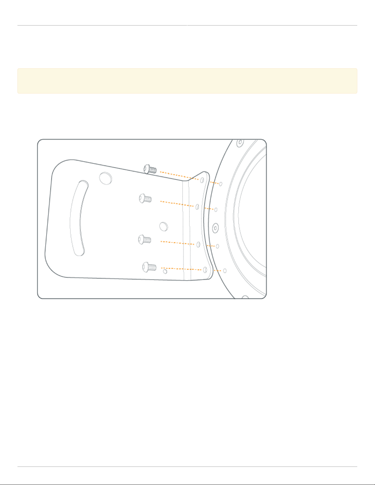
Mimosa Backhaul Help Content Mimosa Backhaul Mounting & Grounding
Mounting and Grounding the B5
This process ensures that the radio is securely attached to a mast/pole up to 90 mm (3.5 inches) in
This process ensures that the radio is securely attached to a mast/pole up to 90 mm (3.5 inches) in
diameter, and grounded to protect against electrical discharge.
diameter, and grounded to protect against electrical discharge.
Follow these steps to mount and ground the B5 Radio.
Using a #4 Allen wrench (eight inches or longer recommended), attach the Bracket Assembly to the back of1.
the B5 with four provided screws.
Remove the two nuts from the same side of the Pole Mount. Feed the bolts through the Bracket Assembly with2.
one bolt through the fixed hole, and the other bolt through the slotted arc. Thread the two nuts onto the bolts
on the outside of the Bracket Assembly, and then tighten loosely (some adjustment is required in a later step).
Copyright © 2014 Mimosa Page 60
Page 67

Mimosa Backhaul Help Content
Mimosa Backhaul Mounting & Grounding
Slide the Pole Mount over the top of the pole as shown in the diagram, rotate the mount around the pole as3.
needed, and then tighten the bolts on the opposite side of the mount to secure. If the top of the pole is
obstructed or inaccessible, disassemble the other side of the Pole Mount and then reassemble it around the
pole.
Aim the radio using physical Elevation and Azimuth movements, then check and tighten each of the bolts until4.
secure.
Attach a 6 mm2 (10 AWG) ground wire with a maximum length of 1 m (3.3 feet) between the Bracket Assembly5.
of the B5 and a suitable grounding location on the tower or structure. The provided grounding screw is M5 x
6mm.
Copyright © 2014 Mimosa Page 61
Page 68

Mimosa Backhaul Help Content
Mimosa Backhaul Mounting & Grounding
Related:
B5 Specifications - See specification sheet section entitled, "Physical" for additional mounting hardware details.
Hardware & Materials - Details about what materials are used in each provided part.
Copyright © 2014 Mimosa Page 62
Page 69

Mimosa Backhaul Help Content
Mimosa Backhaul Mounting & Grounding
Mounting and Grounding the B5c
This process ensures that the radio is securely attached to the tower and is grounded to protect against
This process ensures that the radio is securely attached to the tower and is grounded to protect against
electrical discharge.
electrical discharge.
Insert the open end of each provided Hose Clamp through the slots on the back of the B5c, around the pole1.
and then back into the worm gear (screw portion) of the Hose Clamp. Use a medium sized flat screwdriver to
tighten the Hose Clamp to the pole.
Attach a 6 mm2 (10 AWG) ground wire with a maximum length of 1 m (3.3 feet) to the grounding hole on the2.
back of the B5c and a suitable grounding location on the tower or structure. The provided grounding screw is
M5 x 6mm.
Copyright © 2014 Mimosa Page 63
Page 70

Mimosa Backhaul Help Content
Mimosa Backhaul Mounting & Grounding
Connect the appropriate cable to the Antenna's connector. 3.
Copyright © 2014 Mimosa Page 64
Page 71

Mimosa Backhaul Help Content
Mimosa Backhaul Mounting & Grounding
Mounting and Grounding the B5-Lite
This process ensures that the radio is securely attached to a building or tower and is grounded to protect
This process ensures that the radio is securely attached to a building or tower and is grounded to protect
against electrical discharge.
against electrical discharge.
Follow these steps to mount and ground the B5-Lite Radio.
Attach the Bracket Assembly to a solid surface with four provided bolts. The holes at each end of the Bracket1.
Assembly are spaced at 90 mm (3.54 inches) on center.
Optionally, the bottom portion of the J-mount tube can be separated from the Bracket Assembly and affixed
securely to a commercially available crossover plate with u-bolts, or a traffic camera clamp kit. The J-mount
tube is 38.1 mm (1.5 inches) in diameter.
Copyright © 2014 Mimosa Page 65
Page 72

Mimosa Backhaul Help Content
Mimosa Backhaul Mounting & Grounding
Mount the B5-Lite on the J-Mount using the pipe clamp.2.
Attach a 6 mm2 (10 AWG) ground wire between the B5-Lite and a suitable grounding location. The provided3.
grounding screw is M5 x 6mm.
Copyright © 2014 Mimosa Page 66
Page 73

Mimosa Backhaul Help Content
Mimosa Backhaul Mounting & Grounding
Prepare the Ethernet Cabling (not included) and provided protective boot. Push shielded CAT6 cable through4.
hole in the bottom of the boot, applying the provided dielectric silicone around base of boot around cable
entry. Crimp a metal RJ45 connector to the CAT6 cable and ensure that the cable shield makes contact with
the metal shroud on the RJ45 connector. Apply dielectric silicone around top lip of boot. Pull CAT6 cable back
through boot leaving enough to connect to device. Apply a small amount of dielectric silicone to pins. Insert
the cable into the RJ45 receptacle and attach the boot to the radio body.
Copyright © 2014 Mimosa Page 67
Page 74

Mimosa Backhaul Help Content
Mimosa Backhaul Mounting & Grounding
Aim the radio using physical Elevation and Azimuth adjustments on the J-Mount, then check and tighten each5.
of the 10 mm hex nuts until secure.
Copyright © 2014 Mimosa Page 68
Page 75

Mimosa Backhaul Help Content
Mimosa Backhaul Mounting & Grounding
Mounting and Grounding the B11
The B11 was designed to mate with an antenna using a slip-fit interface. Apply a small amount of o-ring lube to the
dish to ease installation.
Align the radio to the antenna as shown in the photo below and gently apply pressure until the radio seats on the
antenna (you may hear an audible thud when this happens), and then tighten the four bolts with a 5 mm hex key
(Allen) wrench to secure the radio according to the antenna manufacturer's specifications.
Attach a 6 mm2 (10 AWG) ground wire with a maximum length of 1 m (3.3 feet) between the B11 grounding location
on either side of the radio and a suitable grounding location on the tower or structure. The ground screw type and
length is M5 x 6mm.
The larger 14 mm diameter hole under the grounding location was meant for hoisting the radio using a carabineer
before mating the radio to the dish. Do NOT hoist the radio and dish together from this hole.
Related:
B11 Specifications - See specification sheet section entitled, "Physical" for additional mounting hardware details.
Hardware & Materials - Details about what materials are used in each provided part.
Copyright © 2014 Mimosa Page 69
Page 76

Mimosa Backhaul Help Content Mimosa Backhaul Power & Data Connections
PoE Connections
This process ensures the proper PoE connection to a power source, the radio and the LAN.
This process ensures the proper PoE connection to a power source, the radio and the LAN.
Connect the provided power cable between the power over Ethernet (PoE) adapter and a power source. A1.
surge protector can be installed between the PoE and the power source, but it is not required.
Connect a shielded CAT6 Ethernet cable between the Ethernet port labeled "POE" on the GigE PoE adapter and2.
the radio.
Connect a shielded CAT6 Ethernet cable between the Ethernet port labeled "LAN" on the GigE PoE adapter and3.
the LAN side of your network, which is typically a switch or router.
Copyright © 2014 Mimosa Page 70
Page 77

Mimosa Backhaul Help Content
Mimosa Backhaul Power & Data Connections
Related:
LED Status Indicators - External LED behavior based on device status.
Copyright © 2014 Mimosa Page 71
Page 78

Mimosa Backhaul Help Content
Mimosa Backhaul Power & Data Connections
Ethernet Port & IP67 Gland Installation
Product Applicability: B5, B5c, B11
This process ensures that the Ethernet cable is properly secured to the radio and protected from dust and
This process ensures that the Ethernet cable is properly secured to the radio and protected from dust and
moisture.
moisture.
Note 1: To remove the IP67 Cable gland, follow these instructions in reverse. Failure to remove the rubber
Note 1: To remove the IP67 Cable gland, follow these instructions in reverse. Failure to remove the rubber
grommet (Step 5) before disconnecting the body of the IP67 Gland from the radio's locking connector
grommet (Step 5) before disconnecting the body of the IP67 Gland from the radio's locking connector
(Step 4), will result in torsional strain to the Ethernet connector.
(Step 4), will result in torsional strain to the Ethernet connector.
Note 2: Due to the advantages of Mimosa’s IP67 rated cable sealing gland, the application of dielectric
Note 2: Due to the advantages of Mimosa’s IP67 rated cable sealing gland, the application of dielectric
grease to the Ethernet connector or cable gland is neither suggested nor recommended.
grease to the Ethernet connector or cable gland is neither suggested nor recommended.
Process
Separate the IP67 Cable gland into its three parts by unscrewing the body from the cap (with rubber1.
grommet). Remove the rubber grommet and set it aside.
Pass the cap, then body over the end of a shielded CAT6 Ethernet cable.2.
Copyright © 2014 Mimosa Page 72
Page 79

Mimosa Backhaul Help Content
Mimosa Backhaul Power & Data Connections
Insert the CAT6 Ethernet cable into the radio's Ethernet port.3.
Connect the body of the IP67 Gland to the radio's locking connector by twisting it in a clockwise direction until4.
it clicks into place. Do NOT overtighten.
Copyright © 2014 Mimosa Page 73
Page 80

Mimosa Backhaul Help Content
Mimosa Backhaul Power & Data Connections
Place the rubber grommet around the Ethernet cable and squeeze into the body of the IP67 Gland until snug5.
and flush with the Gland bottom.
Screw the cap onto the base of the IP67 Gland body, covering the grommet, until it comes to an effective stop.6.
Copyright © 2014 Mimosa Page 74
Page 81

Mimosa Backhaul Help Content
Mimosa Backhaul Power & Data Connections
B5c IP67 Cable Gland Installation
The IP67 Cable Gland provided with the B5c, and its installation, are the same for the B5c. The image below is
provided for clarity.
Copyright © 2014 Mimosa Page 75
Page 82

Mimosa Backhaul Help Content
Mimosa Backhaul Power & Data Connections
B11 IP67 Cable Gland Installation
Copyright © 2014 Mimosa Page 76
Page 83

Mimosa Backhaul Help Content
Mimosa Backhaul Power & Data Connections
Fiber Port & IP67 Gland Installation
Product Applicability: B11
This process ensures that the SFP is properly secured to the radio and protected from dust and moisture.
This process ensures that the SFP is properly secured to the radio and protected from dust and moisture.
Note: To remove the IP67 gland, follow these instructions in reverse. Failure to remove the rubber
Note: To remove the IP67 gland, follow these instructions in reverse. Failure to remove the rubber
grommet (Step 6) before disconnecting the body of the IP67 gland from the radio's locking connector (Step
grommet (Step 6) before disconnecting the body of the IP67 gland from the radio's locking connector (Step
5), will result in torsional strain to the Ethernet connector.
5), will result in torsional strain to the Ethernet connector.
Mimosa has qualified the following SFP media adapters for use with the Fiber port:
●
Avago AFBR-5710APZ, 850 nm multi-mode IEEE 802.3 Gigabit Ethernet (1.25GBd) - 1000BaseSX
●
Avago AFBR-5715ALZ, 850 nm multi-mode IEEE 802.3 Gigabit Ethernet (1.25GBd) - 1000BaseSX
●
Finisar FTLF8519P3BTL 850 nm multi-mode Gigabit Ethernet (1.25GBd) - 1000BaseSX
●
Finisar FTLF1318P3BTL 1310 nm single mode Gigabit Ethernet (1.25GBd) - 1000BaseSX
Process
Separate the IP67 gland into its three parts by unscrewing the body from the cap (with rubber grommet).1.
Remove the rubber grommet and set it aside.
Insert the SFP module's electrical interface into the receptacle with light finger pressure.2.
Pass the cap, then body over the end of the fiber.3.
Insert the fiber into the SFP fiber port.4.
Connect the body of the IP67 gland to the radio's locking connector by twisting it in a clockwise direction until5.
it clicks into place. Do NOT overtighten.
Place the rubber grommet around the fiber and squeeze into the body of the IP67 gland until snug and flush6.
with the gland bottom.
Screw the cap onto the based of the IP67 gland body, covering the grommet, until it comes to an effective7.
stop.
Press a protective hose (not supplied) over the barbed end of the IP67 gland.8.
Activate the Fiber port to carry data: Preferences > Management > Network Interfaces.9.
Copyright © 2014 Mimosa Page 77
Page 84

Mimosa Backhaul Help Content
Mimosa Backhaul Power & Data Connections
Copyright © 2014 Mimosa Page 78
Page 85

Mimosa Backhaul Help Content Mimosa Backhaul Antenna Connections
B5c Antenna Connections
This process ensures that RF cables are installed securely to the radio and antenna.
This process ensures that RF cables are installed securely to the radio and antenna.
Connect two coaxial cables with Type-N connectors between the B5c and the antenna. Each cable represents1.
a horizontal or vertical polarity.
Once secured mechanically, wrap the connectors with the provided Mastic tape in the clockwise direction to2.
protect against moisture ingress.
Copyright © 2014 Mimosa Page 79
Page 86

Mimosa Backhaul Help Content
Mimosa Backhaul Antenna Connections
Connect the two coaxial cables to the antenna, ensuring that the horizontal and vertical polarizations are3.
connected between the radio and antenna in the same way on both sides of the link (H-H and V-V). Link
performance may be degraded if coaxial cables are swapped between polarizations on one side of the
link. Once secured mechanically, wrap the connectors with the provided Mastic tape in the clockwise direction
to protect against moisture ingress.
Example Antenna Connections
Copyright © 2014 Mimosa Page 80
Page 87

Mimosa Backhaul Help Content
Mimosa Backhaul Antenna Connections
Note: Some antenna inputs are not labeled, or have numbered inputs (e.g. 0 and 1). In this case, consult
Note: Some antenna inputs are not labeled, or have numbered inputs (e.g. 0 and 1). In this case, consult
the antenna manufacturer's documentation to determine the polarization of each input, and ensure that
the antenna manufacturer's documentation to determine the polarization of each input, and ensure that
the cables are connected between the radio and antenna in the same way on both sides of the link.
the cables are connected between the radio and antenna in the same way on both sides of the link.
Copyright © 2014 Mimosa Page 81
Page 88

Mimosa Backhaul Help Content Mimosa Backhaul Backhaul Setup
Backhaul Setup
This overview is intended to assist the user with preliminary radio setup and link tests prior to deployment.
Notes::
Notes
●
Internet access is required to access firmware, unlock codes, and online help resources.
●
Radios must have a good GPS signal to communicate with each other. If configuring radios indoors,
Mimosa recommends either moving the radios near a window/skylight, or employing a GPS repeater
that forwards GPS signals from outdoors to indoors.
●
Care should be taken when setting power levels during indoor tests. Turn the radios away from one
another, separate them by 2 m (>6 feet), and turn the TX Power level down to avoid saturating the
receivers. See Indoor Test Methods for more information.
●
If the radio is connected to a DHCP server, the default IP addresses shown below will be different.
Setup the First Radio (Access Point)
Log in or create a Mimosa Cloud account.1.
Download latest Firmware for your device.2.
Connect the PoE to the Radio.3.
Prepare your computer for use.4.
●
Connect an Ethernet cable between your computer and the PoE port labeled DATA.
●
Ensure that your computer's IP address is different from that of the radio (192.168.1.20), but in the same
network. The subnet mask should be the same for both devices (255.255.255.0). Consult operating system
documentation for instructions about how to change your computer's IP address.
Access the radio in a browser.5.
●
Open a browser and enter 192.168.1.20 in the address bar.
●
Enter a password that will be used to administer the device.
Install firmware image.6.
●
Select the firmware image from your computer downloaded in step 1 for upload. The radio will validate and
install the firmware, and then reboot.
Assign a friendly radio name.7.
●
Navigate to Preferences > General > Device Friendly Name to enter a meaningful radio name.
Configure the radio’s IP address.8.
●
Navigate to Preferences > Management > Management IP to ensure the settings match your existing
network configuration.
●
After changing the radio's IP address adjust your computer's IP address to operate on the same network.
Set the link details.9.
●
Navigate to Wireless > Link > TDMA Configuration to validate that the Wireless mode is set to Access Point.
●
Continue to the Link Configuration panel to set a Link Friendly Name.
Copyright © 2014 Mimosa Page 82
Page 89

Mimosa Backhaul Help Content
Mimosa Backhaul Backhaul Setup
●
Enter an SSID that for the link between the two radios.
●
Enter an Encryption Key (Passphrase) for the link between the two radios.
Choose operating frequencies.10.
●
Navigate to Wireless > Channel & Power > Channel & Power Settings.
●
Choose a desired Channel Width.
●
Choose a desired Center Frequency.
●
Set Tx Power to desired level.
Setup the Second Radio (Station)
Connect the PoE to the radio.1.
Prepare your computer for use.2.
Access the radio in a browser.3.
Install firmware image.4.
Assign a new password and radio name.5.
Configure the radio’s IP address.6.
●
This IP address should be different from the Access Point radio.
Set the link details.7.
●
Navigate to Wireless > Link > TDMA Configuration and change the Wireless Mode to Station.
●
All of the Station's other TDMA Configuration settings will be inherited from the Access Point.
●
Continue to the Link Configuration panel and enter the same SSID and encryption key that were entered on
the Access Point radio.
●
The device will reboot upon saving changes.
The radios should then associate. If configured properly, the Dashboard will show a Wireless Status of Connected.
Copyright © 2014 Mimosa Page 83
Page 90

Mimosa Backhaul Help Content
Mimosa Backhaul Backhaul Setup
Indoor Test Methods
Product Applicability: B5/B5c, B5-Lite
Mimosa recommends confirming Backhaul link connectivity on a test bench before field deployment. This ensures
that each device is in good working order and is properly configured.
Tips for Testing B5 and B5-Lite
The B5 and B5-Lite have fixed antenna gains designed to amplify weak signals in an outdoor environment. While
both radios are indoors, the amplitudes of these signals are much greater, and can saturate the receivers. This can
prevent link connectivity, cause loss of link connectivity, or even damage the receivers. To prevent this from
happening, reduce Tx power on the AP to the lowest setting (-7 dBm for B5; 10 dBm for B5-Lite), and turn the
antennas away from each other. Turning the antennas toward the ceiling, depending on multipath propagation,
usually works best.
Tips for Testing B5c
Although the B5c was designed for use with external antennas, two B5c radios will link without an antenna if placed
immediately next to each other on a work bench. A small amount of RF leakage allows for this to happen, although
the link performance will not represent the outdoor performance, so this method should not be relied upon for
throughput testing.
Alternately, B5c radios can be wired for a conducted test, as shown in the photo below, with short jumper cables, 50
Ohm attenuators and coaxial cable adapters. This configuration better represents outdoor performance, but can
introduce noise depending on the quality of the components between the radios.
Warning: Never connect two B5c radios directly without attenuators. This can damage the receivers and
Warning: Never connect two B5c radios directly without attenuators. This can damage the receivers and
will void the warranty.
will void the warranty.
Copyright © 2014 Mimosa Page 84
Page 91

Mimosa Backhaul Help Content
Mimosa Backhaul Backhaul Setup
Related:
Backhaul FAQ: Should Tx Power be set to maximum?
Copyright © 2014 Mimosa Page 85
Page 92

Mimosa Backhaul Help Content
Mimosa Backhaul Backhaul Setup
Backhaul RF Tuning Process
The Mimosa Backhaul user interface contains a set of tools for selecting channels and adjusting RF parameters. This
document describes how to use each of these to efficiently tune an RF link for optimal performance.
Within this process, it is assumed that the link performance has been modeled and verified using the Mimosa Design
application, and that the antennas have been pointed properly to maximize Rx signal strength using the Aiming
Mode. These are important prerequisites to the RF tuning process that should not be skipped.
Please follow these steps to tune a link for optimal performance:
Use the Site Survey to learn what other devices are detected in the area.1.
Use the Spectrum Analyzer to identify frequencies with the least amount of interference.2.
Use the Channel & Power page to adjust channels, channel width, Tx power and antenna gain (if applicable).3.
Use the Performance Graph to verify that PER is less than 2% on average.4.
Use the MIMO Status Tables to verify that the SNR and MCS support your throughput requirements.5.
Repeat steps 2-5 as necessary.6.
Site Survey
Perform a Site Survey to identify the 802.11 mode, frequency, channel width and signal strength of all AP’s that you
radio detects. Knowing what other devices and device types are in the immediate proximity is important for
collocation of multiple radios, as well as selecting an appropriate channel. More information
Spectrum Analyzer
The next step is to select a channel with the least amount of interference. This is important because throughput
absolutely depends on the signal to noise ratio (SNR). The Spectrum Analyzer can be accessed from either the
Dashboard or by clicking on the Channel & Power page. It actively scans the 5 GHz band to report on interference
sources that may impact link performance by frequency, amplitude, and probability of recurrence. Note that the
Spectrum Analyzer is one of several tools used to measure RF performance, and that you can not depend on it
solely for optimal channel selection. More information
Channel & Power
Since performance depends on maximizing the signal to noise ratio (SNR), use the following settings to target > 30
dB SNR per chain for maximum performance. This table summarizes the SNR required for each MCS.
Channel Settings
Start with a single 20 MHz channel, and then increase channel width and/or number of channels if SNR allows. A
single channel has higher spectral density than two channels. Narrower channels (e.g. 20 MHz) have higher spectral
density than wider channels (e.g. 80 MHz).
Copyright © 2014 Mimosa Page 86
Page 93

Mimosa Backhaul Help Content
Mimosa Backhaul Backhaul Setup
Tx Power Settings
The Maximum transmit power is limited by several factors including the number of channels and the selected
channel. Your regulatory domain may limit the maximum EIRP for certain frequency ranges. On very short links,
decrease Tx power to avoid saturating the receiver.
Antenna Gain Settings
Antenna Gain is fixed on B5 and B5-Lite backhaul radios, so no antenna gain entry field is shown. However, Antenna
Gain is configurable on the B5c because it can be paired with antennas which have various gain values. The
Antenna Gain value is used for two purposes:
To limit the maximum Tx power for each channel based on regulatory domain rules in your country.1.
To calculate the Rx Signal target on the Dashboard. The target will be incorrect if the gain value is inaccurate.2.
More information
Dashboard
Performance Graphs
The Dashboard Performance panel contains two graphs (IP Throughput and PHY PER) that can each be selected by
clicking on the circles at the bottom of the graph. Verify that the PER is below 2% on average after association. More
information
MIMO Status
The Dashboard MIMO Status tables show the SNR per chain and the MCS per stream. If the SNR is low for a
particular channel, try changing channels or move to a smaller channel width. Note that PER and SNR are inversely
proportional. More information
Copyright © 2014 Mimosa Page 87
Page 94

Mimosa Backhaul Help Content Mimosa Backhaul Installation Videos
Videos
B5 Hardware Installation Video
B5 POE and Gland Installation Video
Copyright © 2014 Mimosa Page 88
Page 95

Mimosa Backhaul Help Content
Mimosa Backhaul Installation Videos
Videos
Unboxing
Cloud Account Setup
Obtaining an Unlock Key
Changing Computer IP Address
Powering and Unlocking the B5-Lite
Configuring the Access Point (AP)
Configuring the Station
Installing the B5-Lite
Copyright © 2014 Mimosa Page 89
Page 96

Mimosa Backhaul Help Content Mimosa Backhaul Overview
Accessing the Graphical User Interface
Accessing the graphical user interface (GUI) requires that the radio first be connected to power. The Power over
Ethernet (PoE) connection process describes the steps to do this. Note that the GUI will be available approximately
one minute after applying power.
The GUI can be accessed in three ways to facilitate set-up and management.
Locally through the built-in 2.4 GHz wireless management network (B5/B5c and B11 Only)1.
Through the local Ethernet interface (LAN)2.
Remotely through the Point to Point wireless link3.
Via 2.4 GHz Management Network
On any device with 2.4 GHz 802.11n capability, go to the wireless network listing and connect to the Local Network
Management wireless network (SSID): "mimosaMXXX". The default passphrase for the 2.4 GHz connection is
"mimosanetworks". Once connected, type 192.168.25.1 into your browser. Please note that both the Local Network
Management SSID and passphrase are configurable by the user, so their values could be different from the default
values.
Via Ethernet interface or in-band over the Point to Point link
By default, the device IP address is 192.168.1.20 and can be accessed via the Ethernet port using this IP address in
any standard Web browser. To access the device via a locally connected computer initially (on the same LAN or
directly to the Ethernet port), the computer’s IP address must be on the same subnet as the above address. Once
you have modified the IP address (static or is DHCP) of the device for remote management purposes (in-band over
wireless or over the Ethernet interface), the new specified IP address must be used to access the device. This is
important to do in order to avoid IP address conflicts with other devices on the network. Current IP addresses of
different Mimosa devices on the network can be identified using terminal-based discovery. It is highly recommended
to change the default password to a unique and secured password.
Copyright © 2014 Mimosa Page 90
Page 97

Mimosa Backhaul Help Content
Mimosa Backhaul Overview
Logging In
After connecting via one of the three access methods, the GUI will prompt you to log-in with a password. The
default password is "mimosa", and should be changed immediately after login to protect your network since it gives
the user read / write priveleges. The password can be changed within the Preferences > General > Set Password
panel of the GUI.
If you are looking for the Mimosa Cloud Log In process, please see Manage User Guide: Logging In.
If you are looking for the Mimosa Cloud Log In process, please see Manage User Guide: Logging In.
Copyright © 2014 Mimosa Page 91
Page 98

Mimosa Backhaul Help Content
Mimosa Backhaul Overview
User Interface Overview
When you first log in, you’ll notice that there is a title bar with the device name shown in the top-right corner, a
navigation pane on the left, and a large content pane on the right. The default page shown in the content pane is
the Dashboard, which shows a summary of overall performance at a glance, and highlights both radio and link
parameters that affect link health.
On the left navigation pane, there are four prominent sections: Overview, Wireless, Preferences, and Diagnostics.
Each of these sections contains one or more links to pages containing task-related data, controls, and tools used to
administer the radio…and you can return the Dashboard at any time by clicking on the Dashboard link in the
Overview section.
The pin in the top corner of the left navigation pane allows you to "pin" open the navigation menu for easier access.
Else, the menu contracts to provide more workspace within the GUI. Note that the 2.4 GHz Console menu item is not
present on the B5-Lite.
Copyright © 2014 Mimosa Page 92
Page 99

Mimosa Backhaul Help Content
Mimosa Backhaul Overview
Copyright © 2014 Mimosa Page 93
Page 100

Mimosa Backhaul Help Content Mimosa Backhaul Single Client (PTP) Mode
The Dashboard
The Dashboard contains several panels used to group related items. The status panel at the top of the page shows
the link SSID, the link status, GPS signal quality*, Link Uptime since association, and Link Availability since the last
reboot. Two of the values on this panel contain an information icon that shows more information when you click or
hover over it with your mouse cursor. On other panels, detailed help text can be found by clicking on the
information icon in the upper right hand corner.
* Applies to B5/B5c and B11 only; does not apply to B5-Lite.
Copyright © 2014 Mimosa Page 94
 Loading...