

Page 1

Four Wire Audio Interface
Manual
2013
This document contains proprietary information that
must not be provided or copied to third parties without
express permission from MiMOMax Wireless Limited
Page 2

2
© MiMOMax 2013 Four Wire Audio
Interface Manual
MiMOMax Wireless Ltd
Four Wire Audio Interface Manual 2013
Disclaimer
While precaution has been taken in the preparation of this literature and it is believed to be correct at the time of
issue, MiMOMax Wireless Ltd assumes no liability for errors or omissions or for any damages resulting from the
use of this information. Due to a policy of continuous technical improvement, the contents of this document and
any specifications contained therein are subject to revision and may change without notice.
Page 3

3
© MiMOMax 2013 Four Wire Audio
Interface Manual
TABLE OF CONTENTS
1 OVERVIEW............................................................................................................................. 5
1.1 HIGH SPEED SERIAL INTERFACE (HSSI) .......................................................... 6
1.2 AUDIO ............................................................................................................ 6
1.3 DATA .............................................................................................................. 6
1.4 CONFIGURATION ............................................................................................. 6
2 OPERATION AND CONFIGURATION ................................................................................... 7
2.1 INDICATORS .................................................................................................... 7
2.2 CONNECTIVITY ................................................................................................ 8
2.3 CONFIGURATION ............................................................................................. 8
2.3.1 7 Channel Mode ............................................................................................. 8
2.3.2 3 Channel Mode ............................................................................................. 9
2.3.3 Fixed Channel Mode ...................................................................................... 9
2.3.4 Configuration Selector Access ....................................................................... 9
2.3.5 Configuration Selector Definitions ............................................................... 10
2.4 RADIO UNIT ADVANCED FEATURES ................................................................ 11
2.4.1 On-Demand ................................................................................................. 11
2.4.2 Adaptive Modulation .................................................................................... 11
2.5 BANDWIDTH REQUIREMENTS ......................................................................... 12
2.5.1 Radio Unit Bandwidth .................................................................................. 13
2.6 LATENCY ...................................................................................................... 14
3 POWER ................................................................................................................................ 15
3.1 OVERVIEW .................................................................................................... 15
3.2 CABLING AND CONNECTIVITY ......................................................................... 15
4 AUDIO INTERFACES ........................................................................................................... 16
4.1 OVERVIEW .................................................................................................... 16
4.2 AUDIO .......................................................................................................... 16
4.3 E & M SIGNALLING ........................................................................................ 17
4.4 CABLING AND CONNECTIVITY ......................................................................... 18
4.4.1 Four Wire Audio Connectivity Examples ..................................................... 19
5 DATA INTERFACES ............................................................................................................ 21
5.1 ASYNCHRONOUS SERIAL (COM).................................................................... 21
5.1.1 Overview ...................................................................................................... 21
5.1.2 Cabling and Connectivity ............................................................................. 21
5.2 HIGH SPEED SERIAL INTERCONNECT (HSSI) .................................................. 23
5.2.1 Overview ...................................................................................................... 23
5.2.2 Cabling and Connectivity ............................................................................. 24
5.2.3 HSSI Cross Over ......................................................................................... 25
5.2.4 HSSI Loop Back ........................................................................................... 26
6 INSTALLATION .................................................................................................................... 27
Page 4

4
© MiMOMax 2013 Four Wire Audio
Interface Manual
6.1 FITTING KIT ................................................................................................... 27
6.2 PHYSICAL ..................................................................................................... 27
6.3 RADIO UNIT CONNECTIVITY ........................................................................... 27
6.4 RADIO UNIT CONFIGURATION ......................................................................... 28
7 FIRMWARE UPGRADES ..................................................................................................... 30
8 PRE FIRMWARE VERSION 3.00 CONSIDERATIONS ......................................................... 31
8.1 LED INDICATION ........................................................................................... 31
8.2 AUDIO PORT OPERATION ............................................................................... 31
8.3 CONFIGURATION ........................................................................................... 32
8.4 HIGH SPEED SERIAL INTERFACE (VERSION 1) ................................................. 33
8.5 RADIO UNIT CONFIGURATION ......................................................................... 34
9 TECHNICAL DATA .............................................................................................................. 35
Page 5
5
© MiMOMax 2013 Four Wire Audio
Interface Manual
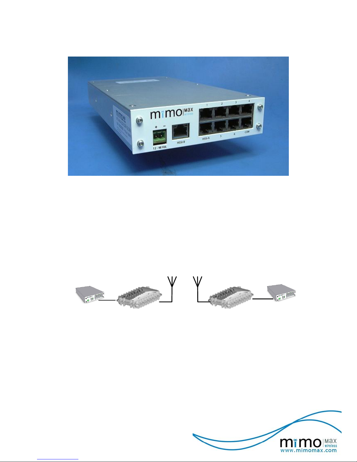
1 OVERVIEW
Four Wire Audio Box
The Four Wire Audio (FWA) interface is a full duplex audio solution with optional E & M
signalling intended for connectivity to equipment requiring an analogue audio interface e.g.
Voice Frequency (VF) modems, or radio systems such as analogue base stations.
Additionally a single EIA232 (UART) interface is provided for end-to-end site communications
at 9600 baud.
The MiMOMax Four Wire Audio interface is provided for by an add-on Network Interface Box
(NIB) which communicates directly with a MiMOMax Radio Unit. The Four Wire Audio
interface is able to be co-located with the Radio Unit in the standard rack mount tray.
Four Wire Audio Solution Overview
The MiMOMax Radio Units plus Four Wire Audio interfaces provide a complete point to point
audio solution where low latency high quality audio is required. When paired with Radio Units
utilizing 16 QAM in a 25 kHz channel, 12 ms latency or better is achievable (A detailed
latency discussion is available in section 2.6)
Page 6
6
© MiMOMax 2013 Four Wire Audio
Interface Manual
1.1 HIGH SPEED SERIAL INTERFACE (HSSI)
The High Speed Serial Interface (HSSI) is a proprietary synchronous serial interface
developed by MiMOMax to enable Network Interface Box’s to be connected to Radio Units.
The connection allows user and configuration data to pass between the two units. User data
presented to the Radio Unit passes to the remote end and ultimately to the terminating
Network Interface Box.
1.2 AUDIO
Up to 6 fully independent transmit and receive audio paths (4 wire connections) are provided
with E&M signalling. Two configuration options are provided, one where an E-Lead signal is
required for audio to pass (dynamic), and the other where the selected audio channels are in
an always up configuration (static).
The audio transport is achieved using a G726 32 kbps ADPCM Vo-coder to offer low latency,
tone transparent high quality audio. The operational frequency range is 65 Hz to 3500 Hz.
1.3 DATA
A single EIA232 compliant data port is provided at 9600 baud (8N1 no hardware flow control)
for inter-site communications. The UART configuration is set in firmware so a special order is
required for an alternate rate. Note that the UART is disabled in Fixed Channel Mode.
1.4 CONFIGURATION
Configuration is provided for by an on board selector switch. Several configuration options are
available including a range of static and dynamic combinations. These are described in
section 2.3.5.
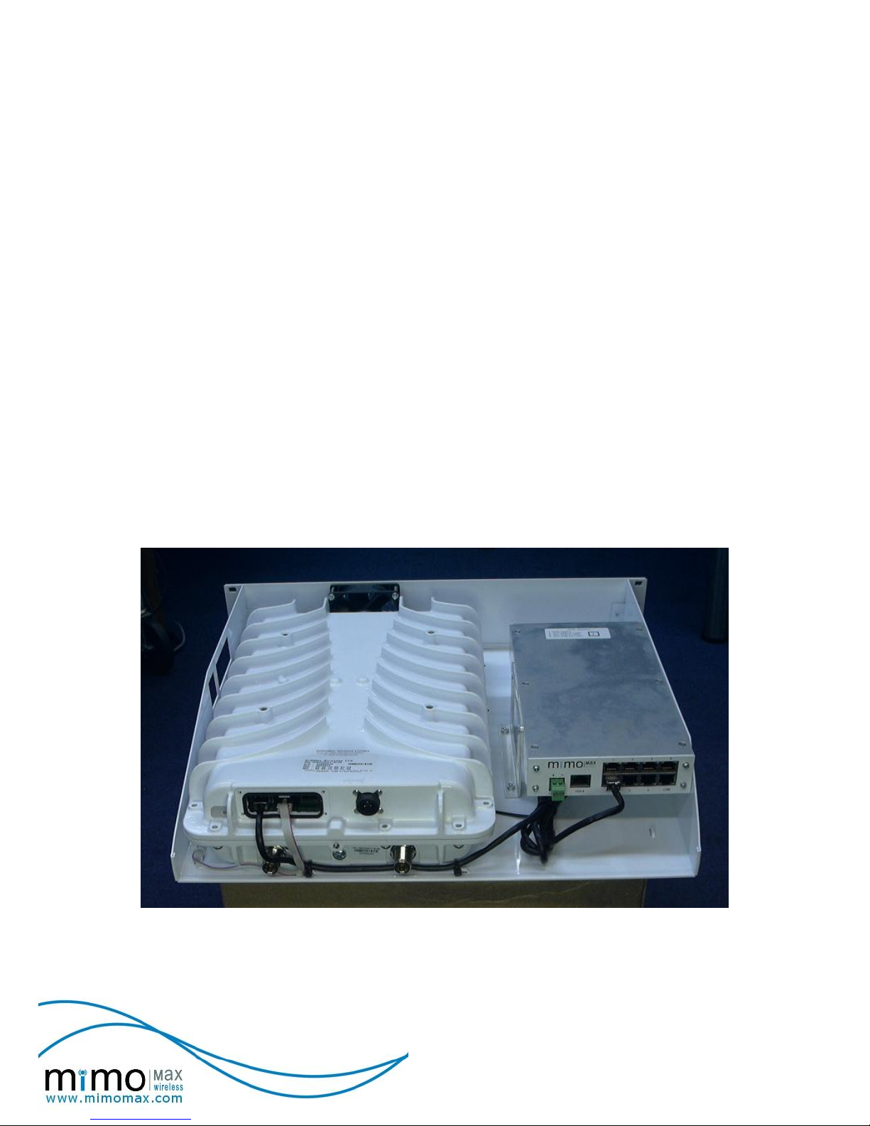
Radio Unit Four Wire Audio Interface Co-Located in the 2U Rack Tray
Page 7
7
© MiMOMax 2013 Four Wire Audio
Interface Manual
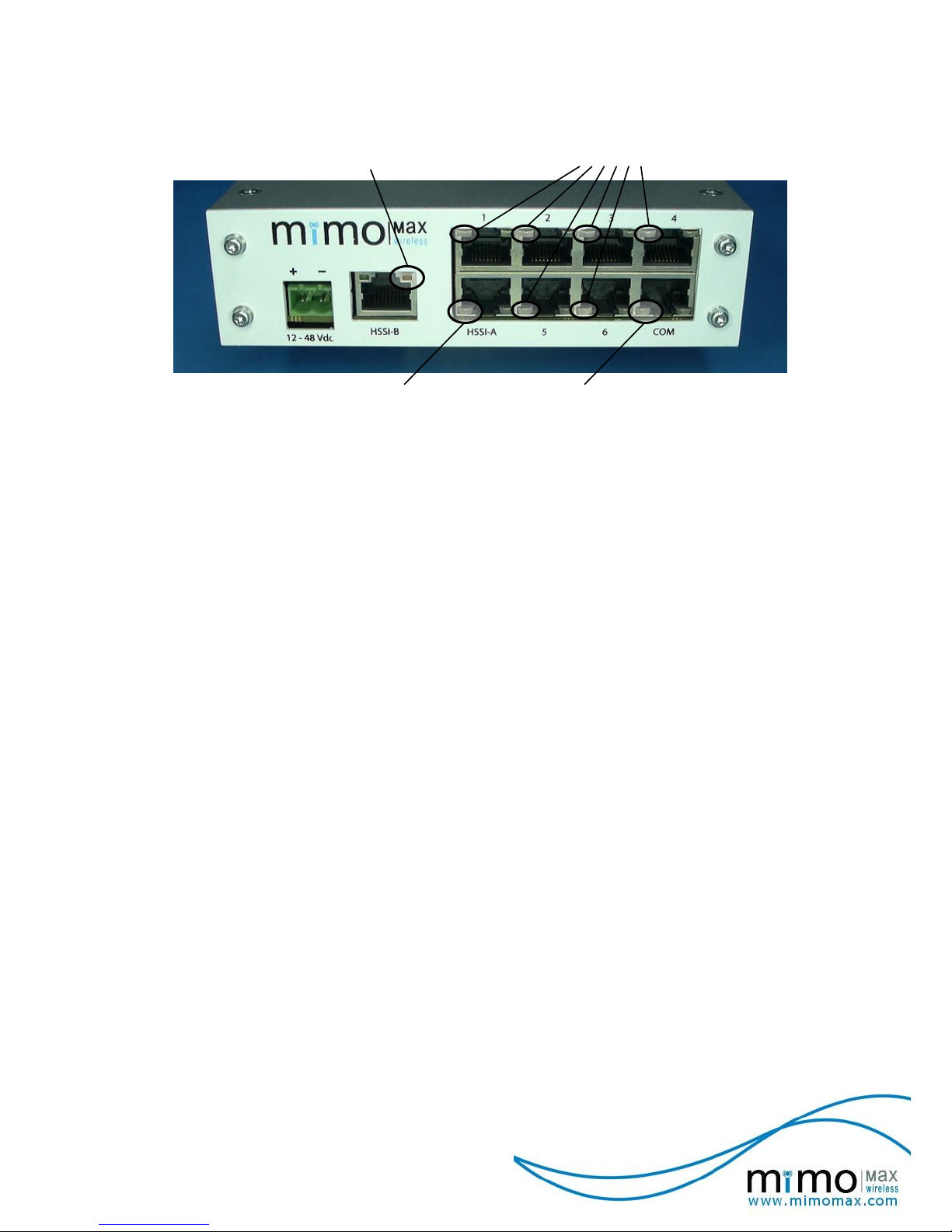
2 OPERATION AND CONFIGURATION
Power LED (orange)
HSSI LED (green) COM LED (green)
Audio Port LEDs (green)
Four Wire Audio Interface Front IO
2.1 INDICATORS
Connector located LEDs provide for indication of unit operation. The unused LEDs are
disconnected and will remain off.
Power LED (orange): On when power applied. Off when no power is applied or a power
fail condition exists.
HSSI LED (green): On when a valid connection is detected. Flashing off to indicate
HSSI port transmit or receive activity and off otherwise
COM LED (green): Nominally off, flashing on to indicate COM port activity (both transmit
and receive).
Audio LEDs (green): On when either the ports transmit or receive path is active and off
otherwise.
(Note: The Audio Port LEDs will remain off if no HSSI link is
available)
Page 8
8
© MiMOMax 2013 Four Wire Audio
Interface Manual
2.2 CONNECTIVITY
Connector
Description
12 – 48 Vdc
Input Power
HSSI-B
(Shielded RJ45)
Not Used (Intended for future enhancements)
HSSI-A
(Shielded RJ45)
Connection to Radio Unit
COM
(Shielded RJ45)
UART Port (EIA232 end-to-end site communications)
Available in 3 and 7 channel Modes (NOT available in Fixed Mode).
1
(Shielded RJ45)
Audio Port One
Available in 3 and 7 channel modes (either static or dynamic operation).
Available in Fixed channel mode.
2
(Shielded RJ45)
Audio Port Two
Available in 3 and 7 channel modes (either static or dynamic operation).
Available in Fixed channel mode.
3
(Shielded RJ45)
Audio Port Three
Available in 7 channel Mode ONLY (either static or dynamic operation).
4
(Shielded RJ45)
Audio Port Four
Available in 7 channel Mode ONLY (either static or dynamic operation).
5
(Shielded RJ45)
Audio Port Five
Available in 7 channel Mode ONLY (either static or dynamic operation).
6
(Shielded RJ45)
Audio Port Six
Available in 7 channel Mode ONLY (either static or dynamic operation).
2.3 CONFIGURATION
Three basic modes of operation are provided; 7 channel, 3 channel and fixed channel. Each
of these modes will define the number of simultaneous audio channels able to operate.
Additionally channels may operate in either dynamic (E & M signalled) or static (always up)
configurations.
Static audio channels pass continuously without an E-Lead signal and the M-Lead signal is
continuously activated. Static channels have a set bandwidth requirement. Dynamic audio
channels are E-Lead controlled where the corresponding M-Lead reflects the state of the ELead. Dynamic channels only consume bandwidth when set as active by the E-Lead signal.
The bandwidth requirement of any selection must be compatible with the supporting radio link
(see Section 2.5).
2.3.1 7 Channel Mode
(6 audio channels plus a data channel plus Control Header)
Audio channels are either always on (static) or controlled via E&M signalling (dynamic). E&M
signalling requires an E-Lead signal for audio to pass.
The data channel passes COM port data as required with the nominal throughput defined by
the UART rate.
Page 9
9
© MiMOMax 2013 Four Wire Audio
Interface Manual
2.3.2 3 Channel Mode
(2 audio channels plus a data channel plus Control Header).
To provide for better bandwidth utilization in situations where only 1 or 2 audio channels are
required the Control Header is reordered to provide for the UART data channel.
Audio channels are either always on (static) or controlled via E&M signalling (dynamic). E&M
signalling requires an E-Lead signal for audio to pass.
The data channel passes COM port data as required with the nominal throughput defined by
the UART rate.
2.3.3 Fixed Channel Mode
(Audio channels only, No data, No Control Header).
To minimize bandwidth requirements only audio data is passed end to end. This places the
limitations of no COM port data and only 2 audio channels. Both channels when enabled
conform to the static configuration as no data passes to indicate their state.
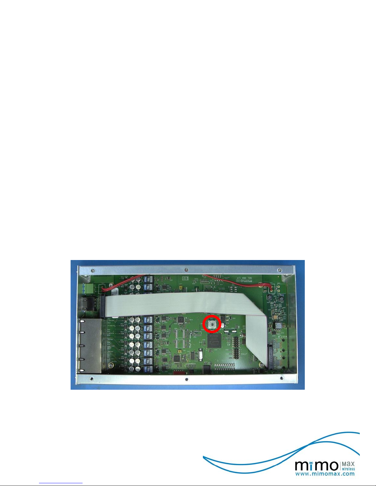
2.3.4 Configuration Selector Access
Observe EMC precautions whenever enclosure is open.
To access the Configuration Selector the unit should first be powered down. The lid may then
be removed to gain access to the selector. Using a suitable tool the selector may be rotated
to the desired selection. The units at both ends of the link must be in compatible modes.
The configuration selector is a single rotary encoder placed on the PCB as shown in the
following image.
Configuration
Selector
Location of Configuration Selector
Page 10

10
© MiMOMax 2013 Four Wire Audio
Interface Manual
2.3.5 Configuration Selector Definitions
The following table lists all options available through the on board selector and the associated
bandwidth requirement ranges.
Position
Description
Bandwidth
Requirement
(bps)
0
Dynamic 7 Channel Mode.
6 audio channels with E&M control. Audio ports 1, 2, 3, 4, 5
and 6 are available.
Single 9600 kbps UART channel.
0 - 233600
1, 2
Fixed Channel Mode.
COM port data is NOT supported.
1: Single fixed audio channel (port 1).
32000
2: Dual fixed audio channels (ports 1 & 2)
64000
3
Dynamic 3 Channel Mode.
2 audio channels with E&M control. Audio ports 1 and 2 are
available.
Single 9600 kbps UART channel.
0 – 96000
4
RESERVED
n/a
5, 6
Static 3 Channel Modes.
5: 1 Static audio channel (port 1), 1 dynamic audio channel
(port 2) plus a single 9600 kbps UART channel.
64000 - 96000
6: 2 Static audio channels (ports 1 & 2) plus a single 9600
kbps UART channel.
96000
7
RESERVED
n/a
8, 9, A,
B, C, D
Static 7 Channel Modes.
8: 1 Static audio channel (port 1) plus 5 dynamic audio
channels (ports 2, 3, 4, 5 & 6) plus a single 9600 kbps UART
channel.
64000 - 233600
9: 2 Static audio channels (ports 1 & 2) plus 4 dynamic audio
channels (ports 3, 4, 5 & 6) plus a single 9600 kbps UART
channel.
96000 - 233600
A: 3 Static audio channels (ports 1, 2 & 3) plus 3 dynamic
audio channels (ports 4, 5 & 6) plus a single 9600 kbps
UART channel.
128000 - 233600
B: 4 Static audio channels (ports 1, 2, 3 & 4) plus 2 dynamic
audio channels (ports 5 & 6) plus a single 9600 kbps UART
channel.
160000 - 233600
C: 5 Static audio channels (ports 1, 2, 3, 4 & 5) plus 1
dynamic audio channels (port 6) plus a single 9600 kbps
UART channel.
192000 - 233600
D: 6 Static audio channels (ports 1, 2, 3, 4, 5 & 6) plus a
single 9600 kbps UART channel.
224000 - 233600
E, F
RESERVED
n/a
Static audio channels do NOT require an E-Lead signal. Any additional supported dynamic
channels may be used with an E-Lead signal.
Fixed Channel Mode channels do NOT require an E-Lead signal.
Page 11

11
© MiMOMax 2013 Four Wire Audio
Interface Manual
2.4 RADIO UNIT ADVANCED FEATURES
The MiMOMax Radio Units have advanced operating modes which the FWA interface
supports.
2.4.1 On-Demand
In the On Demand mode the radio link will go into standby when not required. To support this
feature the FWA interface must be configured such that all audio channels are dynamic
(under E&M control).
When no audio channels are active and no data is being passed the FWA interface will allow
the Radio Link to go into standby. Similarly when an audio channel becomes active or data is
ready to be sent the FWA interface will inform the radio units and thereby bring up the Radio
Link.
Buffering is provided for COM port data such that it is retained for a period to allow the Radio
Link to come up. Following a 200ms timeout period if the Radio Link is still down the data is
deleted.
2.4.2 Adaptive Modulation
Adaptive Modulation allows the Radio Link to scale its data throughput to that supported by
the radio channel. Under normal operation any scaling back of the data is temporary as it is in
response to a transient degradation in the radio channel.
The Four Wire Audio interface will prioritise enabled audio channels based on available
bandwidth. The audio ports priority is sequential with port 1 having the highest priority and
port 6 the lowest. The relationship between the operating RF mode and supported channels is
determined by comparing the bandwidth requirement tables in section 2.5 (Bandwidth
Requirements) with radio unit bandwidth as outlined in the document ‘MiMOMax Radio
Installation and Operation Guide’.
For example: if the audio ports 1, 3 and 5 were enabled and the current radio bandwidth only
supported 2 ports then port 5 would be disabled while ports 1 and 3 would operate as normal.
Once the link bandwidth was restored all 3 ports would operate as normal.
Page 12

12
© MiMOMax 2013 Four Wire Audio
Interface Manual
2.5 BANDWIDTH REQUIREMENTS
The following tables identify the bandwidth requirements of the Four Wire Audio interface. It is
referenced to the selected mode, active audio channels and UART data rate. When audio
channels are dynamic (E & M controlled) the required bandwidth will vary depending on the
active channels at that time.
The required bandwidth must be supported by the connected Radio Units for audio and UART
data to pass successfully.
7 Channel Mode
Required Bandwidth (bps)
Enabled Audio
Channels
No UART
9600 UART
(1)
0 Audio
0
19200
1 Audio
64000
73600
2 Audio
96000
105600
3 Audio
128000
137600
4 Audio
160000
169600
5 Audio
192000
201600
6 Audio
224000
233600
3 Channel Mode
Required Bandwidth
(bps)
Enabled Audio
Channels
No UART
9600 UART
(2)
0 Audio
0
19200
1 Audio
64000
64000
2 Audio
96000
96000
Fixed Channel Mode
Required Bandwidth
(bps)
Enabled Audio
Channels
No UART
9600 UART
(3)
0 Audio
0
N/A
1 Audio
32000
N/A
2 Audio
64000
N/A
NOTE(1) In 7 Channel Mode where at least one audio channel is active the additional
bandwidth required for UART data is equal to the nominal UART data rate. When no audio
channels are active the required bandwidth is twice the UART data rate as the Control
Header is still required.
NOTE (2): In 3 Channel Mode the data bandwidth is carried in the control header. When
no audio channels are active the required bandwidth is twice the UART rate otherwise no
additional bandwidth is required. Nominal rates greater than 9600 bps are NOT supported.
NOTE (3): UART data is not supported in Fixed Channel Mode.
Page 13

13
© MiMOMax 2013 Four Wire Audio
Interface Manual
2.5.1 Radio Unit Bandwidth
The available Radio Unit data bandwidth is defined by the Radio Unit’s RF bandwidth and
modulation settings, some examples are outlined in the following table.
Remaining bandwidth not utilised by the FWA interface may be utilised by other services
supported by the Radio Units such as Ethernet data.
Net Available Radio Unit Bandwidth (bps)
16 QAM
64 QAM
25 kHz
129000
194000
12.5 kHz
65000
97000
Note: For a complete list please refer to the ’About that
MiMOMax Data Rate’ whitepaper.
As an example Radio Units set to 25 kHz / 16 QAM connected to FWA interfaces with the
CTRL selector set to 8 and a UART rate of 9600, would provide the following.
A single static audio channel.
9600 bps UART data.
Up to 55400 bps of Ethernet data.
A single additional dynamic audio channel limiting Ethernet data to 23400 bps when
active.
Alternatively if UART data was not utilised then the following would apply.
A single static audio channel.
Up to 65000 bps of Ethernet data.
Two additional dynamic audio channels limiting Ethernet data to 33000 bps when one is
active and 1000 bps when both are active.
Page 14

14
© MiMOMax 2013 Four Wire Audio
Interface Manual
2.6 LATENCY
End-to-end latency is a combination of audio processing plus Radio Unit latency which is
dependent on Radio Unit RF bandwidth and modulation settings.
Latency introduced by the Radio Units is dependent on the applied RF parameters. As an
example radios with settings of 25 kHz and 16 QAM would provide an additional latency of
6ms. For a complete list please refer to the ‘MiMOMax Radio Installation and Operation
Guide’.
Four Wire Audio interface unit Latency
(As would be achieved by direct connection between two Four Wire Audio interface units).
Audio latency : < 6ms (end-to-end audio delay for active channel)
E&M latency : < 6ms (end-to-end delay for change of state)
Data latency : < 1ms (end-to-end data delay)
Note: E&M Latency includes a de-bounce delay of 5ms where the E-Lead signal must be in
a steady state for 5ms for that state to be recognised. Therefore audio will not be passed until
the transition from inactive to active is recognised. Similarly audio will continue to be passed
until the transition from active to inactive is recognised.
Adding the FWA interfaces and Radio Units latency figures will give an overall end-to-end
latency.
As an example FWA interfaces connected to Radio Units set to 25 kHz and 16 QAM would
provide the following.
Audio latency : 12 ms or better.
EIA232 latency : 7 ms or better (NOTE: independent of interface word
timings).
For Radio Units set up with Power on Demand (M-PoD) additional start up delays will be
experienced as the Air Interface is brought up. For further details please refer to the
‘MiMOMax Radio Installation and Operation Guide’.
Page 15

15
© MiMOMax 2013 Four Wire Audio
Interface Manual
3 POWER
3.1 OVERVIEW
The Four Wire Audio interface contains an isolated pre-regulator followed by local regulators
to individual functional blocks.
The Isolated DC/DC Pre-Regulator accepts an input range of 12 to 48 volts DC and outputs a
DC voltage with a nominal value of 10.5 volts DC.
The absolute minimum and maximum input voltages are 10 and 65 volt DC respectively with
isolation of up to 1500 volts to board circuitry and unit ground being provided.
Where the Radio Units supply meets the above requirements it may also be used to power
the FWA interface.
Isolated DC/DC
Pre-Regulator
(10.5 volts DC)
Board Level Regulation
DC Input -
Filtering
DC Input +
Filtering
10.5 volts DC
Unit
Ground
Circuit Overview
3.2 CABLING AND CONNECTIVITY
Image Showing Power Connected
Power Connector
(Phoenix Contact MSTBA 2,5 HC/2-G-5,08 Header)
Pin
Signal
Polarity
Description
-
NEGATIVE
0 volts
- volts
DC Input
(Polarity must be observed)
+
POSITIVE
+ volts
0 volts
Page 16

16
© MiMOMax 2013 Four Wire Audio
Interface Manual
4 AUDIO INTERFACES
4.1 OVERVIEW
The Four Wire Audio and E&M Signalling Interfaces are intended to provide point-to-point
audio paths as would be required for back-haul linking of PMR base stations and trunking
sites. Additionally the Four Wire Audio interfaces are able to be used for signalling (modems)
as used by protection relays for power system protection and SCADA applications. The Four
Wire Audio interface is able to act as a replacement for copper lines normally used for 4 wire
audio and E&M signals (Note: Modems up to 4800 bps only are supported).
There are six audio channels incorporated into the Four Wire Audio interface where each
audio channel is coded into the G726 32kbps ADPCM format. Dynamic (E&M controlled) and
static (always up, E&M independent) channel operation is supported.
CODEC
PROCESSING
Transformer
(600 ohm)
Audio Data
Four Wire Audio Unit
Transformer
(600 ohm)
8
6
3
5
1
2
4
7
E&M
LOGIC
DC Block
M-Lead
E-Lead
Audio Output
Audio Input
Shield
Four Wire Audio
Port
Circuit Overview
Note: An E-Lead Signal is required for audio to pass unless a ‘Static’ or ‘Fixed’ channel
configuration is selected.
4.2 AUDIO
Each audio port provides a balanced 600ohm transformer-isolated Four Wire Audio interface
and an E&M signalling interface.
There is nominally 0.6dB ±0.3dB of gain in the audio path at 1kHz (This is NON configurable).
The audio transport is achieved using a G726 32 kbps ADPCM vo-coder. This provides tone
transparent high quality audio.
The input audio levels and frequency ranges are as follows.
-20 to +9 dBm (320 – 3500 Hz)
-20 to -10 dBm (65 - 320 Hz)
Voice Frequency modems up to 4800 bps are supported.
Page 17

17
© MiMOMax 2013 Four Wire Audio
Interface Manual
Three modes of operation are supported.
7 channel mode where up to 6 audio channels and a single data channel are available.
3 channel mode where 2 audio channels and a single data channel are available.
Fixed channel mode where 2 audio channels only are available.
The 3 and 7 channel modes provide for static (always up) or dynamic (E&M controlled)
operation while fixed mode provides only for always up operation.
4.3 E & M SIGNALLING
For all dynamic audio channels an E-Lead signal is required for audio to pass through the
system.
For ‘Static’ audio channels an E-Lead signal is NOT required and may be left unconnected.
The M-Lead signal will always reflect the current output audio status of the port independent
of the selected configuration.
A basic E&M signalling interface is provided utilising an opto-isolated switch for the output
(M-Lead) and an opto-isolated current sense input (E-Lead).
The M-Lead will present an on resistance of < 40ohms when active and can support a load
current of up to 100mA over the voltage range of 10V to 50V. The interface is polarity
insensitive.
The E-Lead will detect a current of 5mA or greater as active. Internal current limiting is
provided with a supported voltage range of 10V to 50V. The interface is polarity insensitive.
M Lead
sense (including voltage source)
Pin 7
Pin 8
Internal signal
Four Wire Audio Unit Customer Equipment
The FWA unit internally provides a switch across the M-Lead pins. The external sense
circuit is required to provide its own voltage source which will allow a switch open or closed
state to be sensed.
E Lead
10 to 50 volts DC
Pin 1
Pin 2
sense
Internal signal
sense
Customer EquipmentFour Wire Audio Unit
The FWA unit internally senses a DC voltage across the E-Lead pins. A DC voltage
between 10v and 50v will allow the audio presented to the associated audio port to pass to
the other end.
Page 18

18
© MiMOMax 2013 Four Wire Audio
Interface Manual
4.4 CABLING AND CONNECTIVITY
The recommended cable for the audio connections is unshielded twisted pair.
Four Wire Audio Connector (RJ45 socket)
Pin
Signal
Description
1
E-Lead (SIGNAL)
Signalling Input
2
E-Lead (GND)
Signalling Input
3
Audio Input A
Audio to FWA from Connected Equipment
4
Audio Output A
Audio from FWA to Connected Equipment
5
Audio Output B
Audio from FWA to Connected Equipment
6
Audio Input B
Audio to FWA from Connected Equipment
7
M-Lead (SIGNAL)
Signalling Output
8
M-Lead (GND)
Signalling Output
18
A B
1 8
A B
18
A B
RJ45 Plug (std and shielded)
RJ45 Socket
Stacked RJ45 Socket
RJ45 Pin Numbering
The ports labeled 1 through 6 are audio ports.
Image Showing Audio Cable Connected To Port 5.
Page 19

19
© MiMOMax 2013 Four Wire Audio
Interface Manual
4.4.1 Four Wire Audio Connectivity Examples
FWA-B
FWA-A RU RU
Audio
M_Lead
E_Lead
AudioAudio
M_Lead
E_Lead
Audio
HSSI
HSSI
output
input
sense
sense
output
input
Embedded Audio
Embedded Audio
N/C
N/C
N/C
N/C
Single Channel ‘Static’ Four Wire Audio Example.
Connectivity at FWA A and FWA B shows no E-Lead is required to allow audio to pass. Any
audio presented at one end will be transported to the other.
The FWA A and FWA B graphics show the internal state of the M-Leads as indicating activity
at all times.
Applicable to configuration selections 1 (channel 5), 5 (channel 5), and 6 (channels 5 and 6).
FWA-B
FWA-A RU RU
10 - 50 vDC
Audio
M_Lead
E_Lead
AudioAudio
M_Lead
E_Lead
Audio
0 vDC
HSSI
HSSI
output
input
sense
sense
output
input
Embedded Audio
Embedded Audio
open
closed
Single Channel with E & M signalling Four Wire Audio Example. The intention is to
highlight E-Lead functionality.
Connectivity at FWA A shows no E-Lead signal therefore audio presented does not appear at
FWA B and the M-Lead is not energised.
Connectivity at FWA B shows a valid E-Lead signal and therefore audio passes to FWA A
and the M-Lead is energised.
Applicable to configuration selections 0 (channels 1 through 6) and 3 (Supports 2 audio
channels only, channels 5 and 6).
Page 20

20
© MiMOMax 2013 Four Wire Audio
Interface Manual
FWA-B
Channel 2
Channel 3
Channel 1
FWA-A
Channel 1
Channel 2
0 vDC
10 - 50 vDC
Audio
M_Lead
E_Lead
Audio
10 - 50 vDC
Channel 3
10 - 50 vDC
10 - 50 vDC
0 vDC
Embedded Audio
Embedded Audio
Embedded Audio
Embedded Audio
Embedded Audio
Embedded Audio
closed
closed
open
open
closed
closed
Audio
M_Lead
E_Lead
Audio
Audio
M_Lead
E_Lead
Audio
Audio
E_Lead
M_Lead
Audio
Audio
E_Lead
M_Lead
Audio
Audio
E_Lead
M_Lead
Audio
Multi Channel With E & M Signalling Four Wire Audio Example. The Intention Is To
Show Differing Concurrent Configurations And The Resulting Audio.
Channel 1 shows E-Lead signal at FWA-A only allowing audio to pass from A to B only.
Channel 2 shows E-Lead signal at FWA-A and FWA-B allowing audio to pass in both
directions (A to B and B to A).
Channel 3 shows E-Lead signal at FWA-B only allowing audio to pass from B to A only.
Applicable to configuration selections 0 (channels 1 through 6) and 3 (Supports 2 audio
channels only, channels 5 and 6).
Page 21

21
© MiMOMax 2013 Four Wire Audio
Interface Manual
5 DATA INTERFACES
18
A B
1 8
A B
18
A B
RJ45 Plug (standard and shielded)
RJ45 Socket
Stacked RJ45 Socket
RJ45 Pin Numbering
5.1 ASYNCHRONOUS SERIAL (COM)
5.1.1 Overview
The COM port provides for EIA232 connectivity for end-to-end communications such as Inter
Site Signalling for MPT systems. The supported data rate is 9600 bps.
While no error correction or retry capability is provided an internal 256 byte buffer preserves
data during Radio Unit link anomalies and to support On-Demand (M-PoD) systems. A 200ms
timeout is applied to prevent stale data persisting in the buffer.
232
232
8
6
3
5
1
2
4
Recieve Data
Transmit Data
COM (EIA232) Port
Shield
UART
Data
Four Wire Audio Unit
232
232
NOT USED
NOT USED
7
Circuit Overview
5.1.2 Cabling and Connectivity
Page 22

22
© MiMOMax 2013 Four Wire Audio
Interface Manual
Image Showing COM (EIA232) Cable Connected
COM (EIA232) Connector (RJ45 socket)
Pin
Signal
Description
5
Transmit Data
Data Output From the FWA unit
2
Receive Data
Data Input To the FWA unit
6
Signal Ground
Signal Reference
3
NOT USED
(1)
Output (232 compatible)
7
NOT USED
(1)
Input (232 compatible)
1,4,8
Signal Ground
(1)
Not Used
Shield
Ground
Cable Shield
NOTE (1): For early Four Wire Audio Units (Serial Numbers between 2690065 and 2690109) these lines are not
connected. Although internally connected on later units their use is not currently supported.
RJ45 – DB9 mapping
Signal (FWA unit)
Pin (RJ45)
Pin (DB9)
Tx Data
5
2
Rx Data
2
3
Signal GND
6
5
Page 23

23
© MiMOMax 2013 Four Wire Audio
Interface Manual
5.2 HIGH SPEED SERIAL INTERCONNECT (HSSI)
5.2.1 Overview
The High Speed Serial Interconnect is a full duplex interface with independent transmit and
receive paths. FWA firmware prior to version 3.00 has a HSSI implementation where the
clock and data are separate. Subsequent versions utilise a HSSI v2 implementation where
the clock is embedded with the data. When HSSI v2 is utilised the clock signals provided by
the physical interface are held in a static state and not used. Signalling levels over all HSSI
connections conform to RS422.
The rate of FWA interface frames from the FWA interface to the Radio Unit is 4kHz except
when no ports are active, in which case no frames are sent. Any sent frames will contain data
for all enabled ports at that time.
A single HSSI payload from a Radio Unit to the FWA interface may contain 1 or more FWA
interface frames. These contain the Audio and/or COM port data streams. The frame rate is
dependent on the air interface configuration.
422
422
422
422
8
6
3
5
1
2
7
4
Recieve Clock
Recieve Data
Transmit Clock
Transmit Data
HSSI Port
Shield
HSSI v2 Framer
FWA Data
Four Wire Audio Unit
Circuit Overview
Page 24

24
© MiMOMax 2013 Four Wire Audio
Interface Manual
5.2.2 Cabling and Connectivity
Image Showing HSSI Cable Connected. Note Shielded Plug.
The recommended cable for the HSSI connection is shielded twisted pair similar to Belden
1868E fitted with a shielded RJ-45 plug.
HSSI-A Connector (RJ45 socket)
Provides direct connection to MiMOMax Radio Unit. Utilises a one-to-one connecting lead (shielded cable and plugs).
Pin
Signal
Description
1,2
Transmit Data
Data Output To Radio Unit
7,8
Transmit Timing
Data Timing To Radio Unit
4,5
Receive Data
Data Input From Radio Unit
3,6
Receive Timing
Data Timing From Radio Unit
Shield
Ground
Cable Shield
For connection between the Radio Unit and FWA interface a one-to-one cable is used as
defined in the following table. Radio Unit signals conform to the DCE convention while the
Four Wire Audio interface signals conform to the DTE convention.
RU to FWA interface HSSI Cable
FWA unit : RJ45
Radio Unit : RJ45
Signal
Pin
Pin
Signal
Tx Clock A (output)
8
8
Tx Clock A (input)
Tx Clock B (output)
7
7
Tx Clock B (input)
Tx Data A (output)
2
2
Tx Data A (input)
Tx Data B (output)
1
1
Tx Data B (input)
Rx Clock A (input)
6
6
Rx Clock A (output)
Rx Clock B (input)
3
3
Rx Clock B (output)
Rx Data A (input)
5
5
Rx Data A (output)
Rx Data B (input)
4
4
Rx Data B (output)
Shield / GND
(1)
Body
Body
Shield / GND
NOTE (1): At the Radio Unit GND is isolated from chassis ground. Connection of the ground at each end is required
to ensure correct operation.
Page 25

25
© MiMOMax 2013 Four Wire Audio
Interface Manual
5.2.3 HSSI Cross Over
It is possible to connect 2 Four Wire Audio units back to back for testing where any enabled
audio channel will pass unrestricted, some limitations apply to the COM port while the cross
over is in place.
The Audio ports will behave as they would if the FWA units were part of a normal point to
point system. If a channel is configured for E&M signalling then the E-Lead signal is similarly
required for audio to pass.
The COM port is designed to accommodate on-demand operation so until it can be
determined that the Air Interface is active, data is buffered. Therefore when testing the COM
port with a cross over cable, an audio channel should also be active to ensure unrestricted
data flow.
Image with two Four Wire Audio units connected by a HSSI crossover cable
HSSI X-Over Cable
Unit One : RJ45
Unit Two : RJ45
Signal
Pin
Pin
Signal
Tx Clock A 8 6
Rx Clock A
Tx Clock B 7 3
Rx Clock B
Tx Data A 2 5
Rx Data A
Tx Data B 1 4
Rx Data B
Rx Clock A 6 8
Tx Clock A
Rx Clock B 3 7
Tx Clock B
Rx Data A 5 2
Tx Data A
Rx Data B 4 1
Tx Data B
Shield / GND
Body
Body
Shield / GND
Page 26

26
© MiMOMax 2013 Four Wire Audio
Interface Manual
5.2.4 HSSI Loop Back
It is possible to create a HSSI loop back cable for testing that allows a FWA unit to be
operated by itself where any enabled port will be directly looped back, this applies to both
audio and COM ports although limitations apply to the COM port while the loop back is in
place.
The Audio ports will behave as they would if the FWA unit was part of a normal point to point
system. If a channel is configured for E&M signalling then the E-Lead signal is similarly
required for audio to pass.
As the COM port will buffer the then delete data unless it can be determined that the air
interface is active an audio channel should also be active to ensure unrestricted data flow
when testing the COM port with a loop back cable.
Image Showing Loop Back Cable In Place.
HSSI Loop Back Connections
Signal
Pin (RJ45)
Pin (RJ45)
Signal
Tx Clock A
8
6
Rx Clock A
Tx Clock B
7
3
Rx Clock B
Tx Data A
2
5
Rx Data A
Tx Data B
1
4
Rx Data B
Page 27
27
© MiMOMax 2013 Four Wire Audio
Interface Manual
6 INSTALLATION
6.1 FITTING KIT
Description
Qty
MiMOMax Part Number
Mounting Bracket 1 302-06015-00
Screw M4x8 Pan Head
4
349-02059-00
Screw M4x10 Counter Sunk
2
349-02060-00
HSSI Cable
1
219-03337-00
Power connector and cable
1
219-03335-00
6.2 PHYSICAL
The image opposite shows the Four
Wire Audio unit mounted in the rack
mount tray.
The 2 M4x10 counter sunk screws
attach the mounting bracket to the
rack mount tray. These are visible in
the opposite image.
The 4 M4x8 pan head screws are
used to attach the FWA box to the
mounting bracket and the rack
mount tray. The 2 screws attaching
the FWA box to the mounting
bracket are visible in the opposite
image.
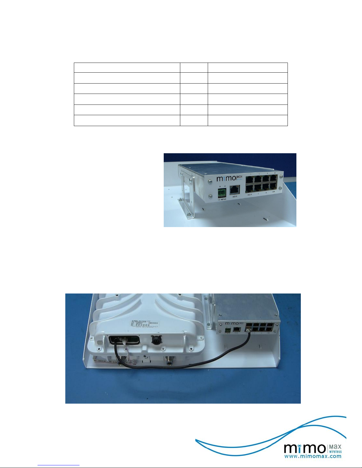
6.3 RADIO UNIT CONNECTIVITY
Image Of Radio Unit And Four Wire Audio Interface Co-Located In The Rack Mount
Tray, With Shielded Connecting Cable In Place.
Page 28

28
© MiMOMax 2013 Four Wire Audio
Interface Manual
The image opposite shows
the shielded HSSI cable
connected to the
Synchronous Serial port of
the Radio Unit.
6.4 RADIO UNIT CONFIGURATION
Radio Unit configuration is achieved through the CCMS web application. At this stage the
FWA interface is unable to be configured from CCMS. For additional information regarding
Radio Unit configuration please refer to the ‘MiMOMax Radio Installation and Operation
Guide’.
On the ‘Configure Serial Interfaces’ CCMS web page the mode needs to be set to HSSI2.
CCMS Screen Capture Showing HSSI2 Selection Following The Save Action.
Having selected and applied ‘HSSI2’ the radio will query the connected interface and display
any returned information and status. An example of the information and status can be seen in
figure ‘CCMS screen capture showing FWA interface status display’. The Radio will also
apply any items necessary to support the connected interface. The HSSI2 mode supports
interfaces other than FWA.
Page 29

29
© MiMOMax 2013 Four Wire Audio
Interface Manual
CCMS Screen Capture Showing FWA Interface Status Display.
The CCMS Four Wire Audio status display is updated by selecting the ‘Refresh’ button. The
status will NOT update automatically.
Page 30

30
© MiMOMax 2013 Four Wire Audio
Interface Manual
7 FIRMWARE UPGRADES
Firmware upgrades may only be performed at a MiMOMax Wireless service centre. If you
require a firmware upgrade please contact MiMOMax Wireless directly for the location of the
nearest service centre.
Page 31

31
© MiMOMax 2013 Four Wire Audio
Interface Manual
8 PRE FIRMWARE VERSION 3.00 CONSIDERATIONS
8.1 LED INDICATION
Only the LEDs in the following diagram (Power, HSSI and COM) provide an indication of
operation. Audio Port LEDs do NOT provide any indication in products with firmware pre
version 3.00.
Power LED (orange)
HSSI LED (green)
COM LED (green)
Four Wire Audio Interface Front IO
Power LED (orange): On when power applied. Off when no power is applied or a power fail
condition exists.
HSSI LED (green): Nominally off, flashing on to indicate HSSI port activity (both transmit and
receive). Note In certain modes the HSSI port is continuously active, as is the case when
audio channels are configured for static or fixed operation.
COM LED (green): Nominally off, flashing on to indicate COM port activity (both transmit and
receive).
8.2 AUDIO PORT OPERATION
For pre version 3.00 firmware the operating modes of the Audio Ports are as follows.
Audio Port
Operating Modes
One
7 channel mode ONLY in either static or dynamic operation.
Two
7 channel mode ONLY in either static or dynamic operation.
Three
7 channel mode ONLY in either static or dynamic operation.
Four
7 channel mode ONLY in either static or dynamic operation.
Five
3 and 7 channel modes in either static or dynamic operation.
Fixed channel mode (no UART).
Six
3 and 7 channel modes in either static or dynamic operation.
Notable differences compared to version 3.00 and later are:
1. Only a single Fixed Channel is supported and the utilised port is different.
2. The ports utilised for 3 channel mode are different.
Page 32

32
© MiMOMax 2013 Four Wire Audio
Interface Manual
8.3 CONFIGURATION
The following table outlines the operation of given selector settings for units with pre version
3.00 firmware.
Configuration Selector Definitions
Position
Description
Bandwidth
Requirement
(bps)
0
Dynamic 7 Channel Mode.
6 audio channels with E&M control (ports 1, 2, 3, 4, 5 & 6) plus a
single 9600 kbps UART channel.
To enable Audio on a given channel an E-Lead signal is required.
0 - 233600
1
Fixed Channel Mode (UART data is ignored).
Single static audio channel (Port 5).
Audio on Port 5 (An E-Lead signal is NOT required).
32000
2
RESERVED
n/a
3
Dynamic 3 Channel Mode.
2 audio channels with E&M control (ports 5 & 6) plus a single 9600
kbps UART channel.
To enable Audio on a given port an E-Lead signal is required.
0 – 96000
4
RESERVED
n/a
5, 6
Static 3 Channel Modes. Two options are available utilizing audio
channels 5 and 6.
5: 1 Static audio channel (port 5), 1 dynamic audio channel (port 6)
plus a single 9600 kbps UART channel.
64000 - 96000
6: 2 Static audio channels (ports 5 & 6) plus a single 9600 kbps
UART channel.
96000
Static audio channels do NOT require an E-Lead signal; any
additional supported dynamic channels may be used with an E-Lead
signal.
7
RESERVED
n/a
8, 9, A,
B, C, D
Static 7 Channel Modes. Six options are available utilizing all audio
channels (1 through 6).
8: 1 Static audio channel (port 5), 5 dynamic audio channels (ports
6, 4, 3, 2 & 1) plus a single 9600 kbps UART channel.
64000 - 233600
9: 2 Static audio channels (ports 5 & 6), 4 dynamic audio channels
(ports 4, 3, 2 & 1) plus a single 9600 kbps UART channel.
96000 - 233600
A: 3 Static audio channels (ports 5, 6 & 4), 3 dynamic audio
channels (ports 3, 2 & 1) plus a single 9600 kbps UART channel.
128000 - 233600
B: 4 Static audio channels (ports 5, 6, 4 & 3), 2 dynamic audio
channels (ports 2 & 1) plus a single 9600 kbps UART channel.
160000 - 233600
C: 5 Static audio channels (ports 5, 6, 4, 3 & 2), 1 dynamic audio
channel (port 1) plus a single 9600 kbps UART channel.
192000 - 233600
D: 6 Static audio channels (ports 5, 6, 4, 3, 2 & 1) plus a single 9600
kbps UART channel.
224000 - 233600
Static audio channels do NOT require an E-Lead signal; any
additional supported dynamic channels may be used with an E-Lead
signal.
E, F
RESERVED
n/a
Notable differences compared to version 3.00 and later are:
1. Only a single Fixed Channel is supported and the utilised port is different.
2. The order of enabled ports is different for 3 and 7 channel modes.
3. The ports utilised for 3 channel mode are different.
Page 33

33
© MiMOMax 2013 Four Wire Audio
Interface Manual
8.4 HIGH SPEED SERIAL INTERFACE (VERSION 1)
For Firmware pre version 3.00 HSSI v1 is utilized and is not compatible with HSSI V2, as
used with Firmware version 3.00 and later.
The nominal bit rate for the HSSI v1 interface is 1Mbps.
422
422
422
422
8
6
3
5
1
2
7
4
Recieve Clock
Recieve Data
Transmit Clock
Transmit Data
HSSI Port
Shield
HSSI v1 Framer
FWA Data
Four Wire Audio Unit
HSSI Circuit Overview
HSSI v1 utilises clock and data signals in each direction with the connections outlined in the
above figure ‘Circuit Overview’ and the following table.
RU to FWA interface HSSI Cable
FWA unit : RJ45
Radio Unit : RJ45
Signal
Pin
Pin
Signal
Tx Clock A (output)
8
8
Tx Clock A (input)
Tx Clock B (output)
7
7
Tx Clock B (input)
Tx Data A (output)
2
2
Tx Data A (input)
Tx Data B (output)
1
1
Tx Data B (input)
Rx Clock A (input)
6
6
Rx Clock A (output)
Rx Clock B (input)
3
3
Rx Clock B (output)
Rx Data A (input)
5
5
Rx Data A (output)
Rx Data B (input)
4
4
Rx Data B (output)
Shield / GND
(1)
Body
Body
Shield / GND
NOTE (1): At the Radio Unit GND is isolated from chassis ground. Connection of the ground at each end is required
to ensure correct operation.
Page 34

34
© MiMOMax 2013 Four Wire Audio
Interface Manual
8.5 RADIO UNIT CONFIGURATION
Radio Unit configuration is achieved through the CCMS web application.
A radio link utilising adaptive modulation (M-CAM) is NOT supported.
On the ‘Configure Serial Interfaces’ CCMS web page the mode needs to be set to HSSI.
Serial Interfaces CCMS Web Page Showing HSSI Selection
For further details on Radio Unit configuration please refer to the document ‘MiMOMax Radio
Installation and Operation Guide’.
Page 35

35
© MiMOMax 2013 Four Wire Audio
Interface Manual
9 TECHNICAL DATA
Audio
Connector
RJ45
Number of Channels
6
Input Range to Unit
-20 dBm to +9dBm (320 – 35000 Hz)
-20 dBm to -10dBm (65 – 320 Hz)
Insertion Loss
+0.6 dB (±0.3 dB) @ 1000 Hz
Frequency Range
65 Hz to 3500 Hz
Nominal Impedance
600 ohm
Latency
(1)
<6ms
E&M Signaling
Connector
RJ45 (co-located with audio)
Type
current sense input / switch output
Latency
(1)
<6ms
(2)
UART (EIA232) Data
Connector
RJ45
Data Rate
9600 (Set in Firmware and NOT user
configurable)
Latency
(1)
<1ms
(3)
Network (HSSI) Port
Connector
RJ45
Protocol
Proprietary for direct connection to MiMOMax
Radio Units
Power
Connector
Detachable screw terminal
Type
Isolated DC/DC converter
Isolation
1500 volts
Nominal Input Voltage
12 to 48 VDC
Operational Input voltage
10 to 64 VDC
Power
<1.5 W
Mechanical Dimension
38mm x 140mm x 258mm (H x W x D)
Environmental
Temperature (operational)
- 25 ºC to 60 ºC
Humidity (operational)
4% to 100% (per EN 300 019 sec. 3.3 & 4.2H)
Altitude (operational)
0 to 3000m
Environmental Protection
IP20 (Indoor use only)
NOTE (1): Quoted latencies are for back-to-back connected FWA units. For audio channels this is for audio
following channel initialisation. The total end-to-end latency will require addition of latency through the Radio Units.
Channel establishment is NOT included.
NOTE (2): E & M latency includes a 5ms de-bounce delay.
NOTE (3): For the UART the quoted delay does not account for the interface transmission delay (e.g. the
time to transfer a word between the connected UARTs at either end).
 Loading...