

Page 1

QUAD ARRAY LOOP YAGI ANTENNA
ASSEMBLY AND INSTALLATION INSTRUCTIONS
1
Page 2

Quad – Array Loop Yagi Antenna
Packing Contents
Array frame pack
Antennas
(Packaged separately) 4 x 450 - 470MHz Antenna
Tools required
1 x 10mm socket
1 x 10mm spanner
1 x Cutters (for cable ties)
Assembly Instructions
1. Arrange the 4 frame parts as shown in Fig.’s 1 & 2 below.
Note: There are labels on each piece showing which antenna array they are
for, which part number it is and what joins go where. Arrange them so the join
numbers are next to each other.
Fig.1 - Frame assembly
2. Use 16x spring washers, 16x M6x16 bolts and 16x M6 nuts to assemble the
frame together.
4 x frame parts labelled part 1-4
8 x clamp halves
8 x M6x100 bolts
32 x M6x16 bolts
32 x M6 nuts
48 x M6 spring washers
2 x 450-470MHz Splitters
20 x cable ties
1 x Instruction document
(ANT 450-470-010-YDXX)
Fig.2 - Part labels
2
Page 3

4 clamps
3. Unpack the 4 Antennas. Each one is labelled with Ant: 1-4. Each antenna
must be put in a specific place on the array, ensure that the Ant: 1- 4 labels
on the Antenna, match the Ant: 1-4 labels on the frame (see Fig.3). Use 4 x
spring washers and 4 x M6x16 bolts to secure each antenna to the frame
(nuts not required, antennas have pressed insert nuts).
Fig.3 - Antenna labels
Note: The "this side down" label on each antenna must face down when the array is
installed. This ensures the drain holes on the antennas are correctly orientated.
4. Bolt the 4 clamp halves to the rear of the frame using 8 x M6x100 bolts, 8 x
spring washers and 8 x M6 nuts (see Fig. 4 & 5). Place the spring washer
between the bolt head and the frame (see Fig.6).
.
Fig.4 - Pole Clamp positions
3
Page 4

Horizontal splitter
Vertical splitter
Fig.5 – Clamp bolt & nut Fig.6 - Bolt head with spring washer
Note: The nut will be difficult to tighten due to its location in the clamp - its only
required to hold the clamp in place until the rear clamp is fitted.
5. Run the Antenna cables, as shown in Fig.7, to each splitter. Create an
approx. 100mm diameter loop in each of the 'vertical' cables of the bottom 2
antennas (see fig.7) to use up the slack.
Note: Do not cut or alter the length of the cables, they are phase matched. All cables
labelled 'Vertical' must go to the lower splitter, all cables labelled 'Horizontal' must go
to the upper splitter.
Run all 'horizontal'
cables here.
Run all 'vertical'
cables here.
Fig.7 - Colour coded cable runs
4
Page 5
6. Tighten each of the N-type connectors to the splitters.
7. Using an appropriate self-vulcanising rubber tape, or similar means, seal the
4 antenna connections to each splitter. The joints must be water tight and UV
resistant (unless antenna is to be installed indoors).
Note: For easy installation, it is recommended that a coax tail be connected to the
central connector of each splitter and the connection waterproofed in the same way
as the other connections. This will allow the splitter to be mounted to the array frame
before the array is installed on the pole
8. Cable tie each splitter into place as shown in Fig.8 using 4 x cable ties.
9. Cable tie cables so they are held neatly in place and cannot chafe against
metalwork.
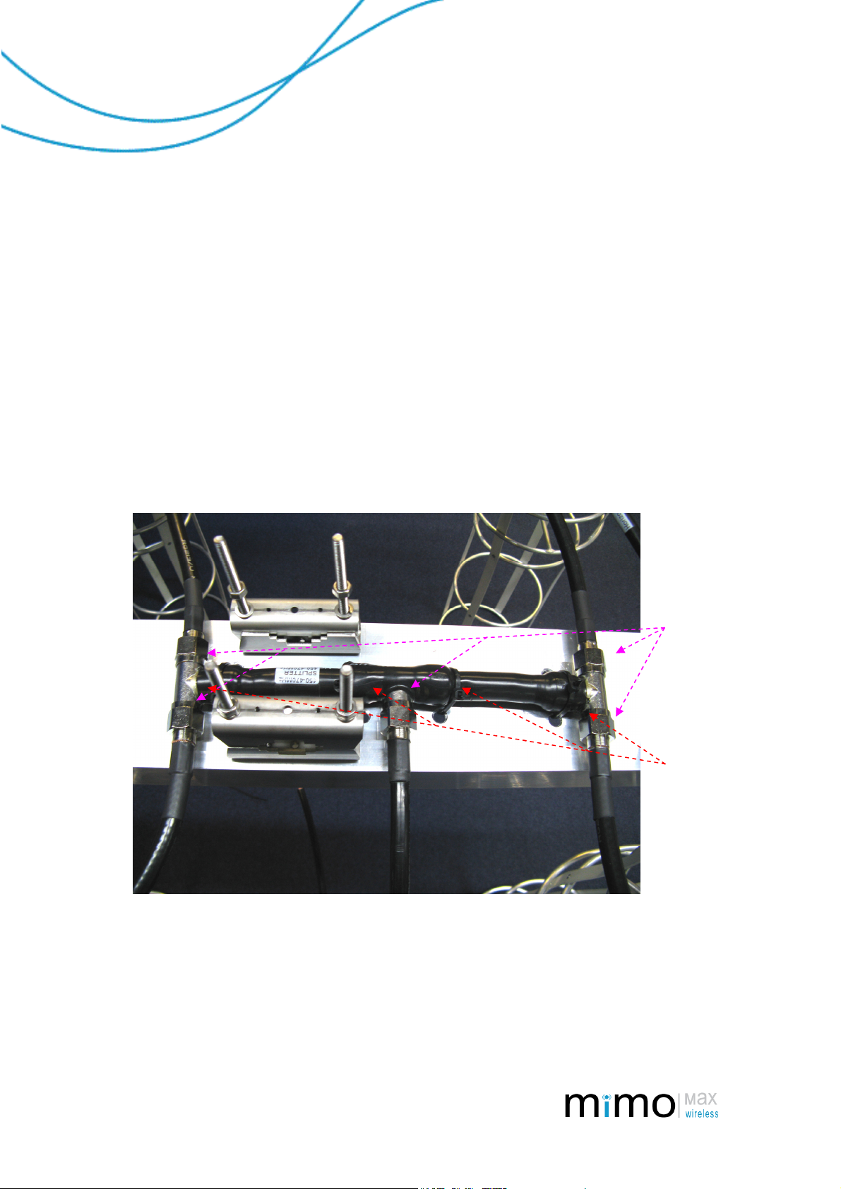
Fig.8 - Splitter mounting and waterproofing
The antenna array is now ready to be fitted to its pole.
Waterproof
these 5 joins
with selfvulcanising
rubber tape
or similar
means.
Cable tie
splitters in
these 4
positions.
5
Page 6

Installation Instructions
Note: Recommended pole size is 38-52mm OD, to ensure stability.
1. Lift the antenna array into place on the pole at the desired height. Place 4x
clamp halves over the long bolts so pole is between 2 clamp halves. Place a
spring washer and nut on each bolt. Tighten enough so the antenna does not
fall down, but not so tight that it can’t be rotated on the pole.
2. Rotate the array to the desired direction and tighten the nuts fully.
3. Attach coax tails to their mating cables and tape up using an appropriate selfvulcanising rubber tape or similar means. All joints must be water tight and
UV resistant (Unless antenna is to be installed indoors).
4. Cable tie the cable run to the antenna array so cable is held firmly and neatly
in place and there is no strain on connectors.
DISCLAIMER:
Whilst every precaution has been taken in the preparation of this literature and it is believed to be
correct at time of issue, MiMOMax Wireless Ltd assumes no liability for errors or omissions or for any
damages resulting from the use of this information. Due to a policy of continuous technical
improvement the contents of this document and any specifications contained therein are subject to
revision and may change without notice.
6
 Loading...