

Page 1

D202007-14
MIMAKI ENGINEERING CO., LTD.
URL: http: // www.mimaki. co. jp/
Page 2

1
Foreword ..................................................................3
CAUTION ..................................................................4
DISCLAIMER OF WARRANTY ................................ 4
Requests ..................................................................4
FCC Statement (USA) ..............................................4
Interference to televisions and radios .......................4
About media .............................................................4
Safety Precautions ..................................................5
Symbols ....................................................................5
Safety Labels ............................................................7
CWhere to install this machine ..............................8
Configuration and function ....................................9
The Front ..................................................................9
The Rear .................................................................10
Operation Panel ......................................................11
Connecting the cables .......................................... 12
USB Cable Connection ...........................................12
RS-232C Cable Connection ...................................12
Connecting the power cable ...................................13
Operation flow ....................................................... 14
Installing a tool ......................................................15
Using a cutter .........................................................15
How to Install a Ballpoint Pen .................................18
Turning the power on ............................................19
Setting the tool conditions ...................................20
Kinds of the Tool Conditions ...................................20
Set the Tool Conditions. .........................................21
Loading a sheet of media .....................................23
Loading a leaf sheet (cut sheet) .............................26
How to Place the Roll Sheet ...................................28
Test cutting (plotting) ............................................31
Cutting (plotting) ................................................... 32
Setting the origin .....................................................32
Start cutting (plotting) .............................................33
Cut off the Sheet (Manual Cutting) ......................... 34
Turning the power off ............................................35
TABLE OF CONTENS
Page 3

2
Cut Out Data with Registration Mark ...................36
Making sticker with a register mark
(When using FineCut) ............................................ 36
Making sticker with a register mark
(W h e n u s i n g S i m p l e C u t ) ............................................ 37
Enter the registration mark detection mode ........... 38
Precautions in inputting data with registration
marks ..................................................................... 39
Set for Detecting the Registration Marks ............... 43
Method of detecting registration marks .................. 48
Confirm the following when failed in cutting
correctly. ................................................................. 57
Page 4

3
Foreword
Congratulations on your purchase of Mimaki cutting plotter CG-SRII series.
This guide explains basic operation of CG-SRII.
For more details, please refer to the “CG-SRII series Operation Manual” supplied with the attached operation manual CD-ROM.
You can also download the latest quick reference guide from our website.
Page 5

4
CAUTION
DISCLAIMER OF WARRANTY
DISCLAIMER OF WARRANTY : THIS LIMITED WARRANTY OF MIMAKI SHALL BE THE SOLE AND
EXCLUSIVE WARRANTY AND IS IN LIEU OF ALL OTHER WARRANTIES,EXPRESS OR IMPLIED,
INCLUDING, BUT NOT LIMITED TO, ANY IMPLIED WARRANTY OF MERCHANTABILITY OR FITNESS,
AND MIMAKI NEITHER ASSUMES NOR AUTHORIZES DEALER TO ASSUME FOR IT ANY OTHER
OBLIGATION OR LIABILITY OR MAKE ANY OTHER WARRANTY OR MAKE ANY OTHER WARRANTY
IN CONNECTION WITH ANY PRODUCT WITHOUT MIMAKI’S PRIOR WRITTEN CONSENT. IN NO
EVENT SHALL MIMAKI BE LIABLE FOR SPECIAL, INCIDENTAL OR CONSEQUENTIAL DAMAGES OR
FOR LOSS OF PROFITS OF DEALER OR CUSTOMERS OF ANY PRODUCT.
Requests
• This Operation manual has been carefully prepared for your easy understanding.However, please do
not hesitate to contact a distributor in your district or our office if you have any inquiry.
• Description contained in this Operation manual are subject to change without notice forimprovement.
FCC Statement (USA)
This equipment has been tested and found to comply with the limits for a Class A digital device,pursuant to
Part 15 of the FCC Rules. These limits are designed to provide reasonable protection against harmful
interference when the equipment is operated in a commercial environment. This equipment generates,
uses and can radiate radio frequency energy and, if not installed and used in accordance with the Operation
manual, may cause harmful interference to radio communications. Operation of this equipment in a
residential area is likely to cause harmful interference in which cause the user will be required to correct the
interference at his own expense.
Interference to televisions and radios
The product described in this manual generates high frequency when operating.
The product can interfere with radios and televisions if set up or commissioned under improper conditions.
The product is not guaranteed against any damage to specific-purpose radio and televisions.
The product’s interference with your radio or television will be checked by turning on/off the power switch of
the product.
In the event that the product is the cause of interference, try to eliminate it by taking one of the following
corrective measures or taking some of them in combination.
• Change the orientation of the antenna of the television set or radio to find a position without reception
difficulty.
• Separate the television set or radio from this product.
• Plug the power cord of this product into an outlet which is isolated from power circuits connected to the
television set or radio.
About media
Please follow the local regulations to dispose of roll sheets or other media.
• In the case where MIMAKI-recommended cable is not used for connection of this device, limits
provided by FCC rules can be exceeded.To prevent this, use of MIMAKI-recommended cable
is essential for the connection of this plotter.
Page 6
5
Safety Precautions
Symbols
Symbols are used in this Operation Manual for safe operation and for prevention of damage to the machine.
The indicated sign is different depending on the content of caution.
Symbols and their meanings are given below. Please follow these instructions as you read this manual.
Examples of symbols
Meaning
Failure to observe the instructions given with this symbol can result in death or serious injuries to
personnel. Be sure to read and observe the instructions for proper operation.
Failure to observe the instructions given with this symbol can result in injuries to personnel or
damage to property.
This symbol indicates that the information is helpful in proper operation of the plotter.
This symbol indicates that it is important to know of the information on proper operation of the
plotter.
Use this information for your operation.
Indicates the reference page for related contents.
The symbol " “indicates that the instructions must be observed as strictly as the CAUTION
instructions (including DANGER and WARNING instructions). A sign representing a precaution
(the sign shown at left warns of hazardous voltage) is shown in the triangle.
The symbol " “indicates that the action shown is prohibited. A sign representing a prohibited
action (the sign shown at left prohibits disassembly) is shown in or around the circle.
The symbol " “ indicates that the action shown must be taken without fail or the instructions
must be observed without fail. A sign representing a particular instruction (the sign shown at left
instructs to unplug the cable from the wall outlet) is shown in the circle.
Page 7
6
Safety Precautions
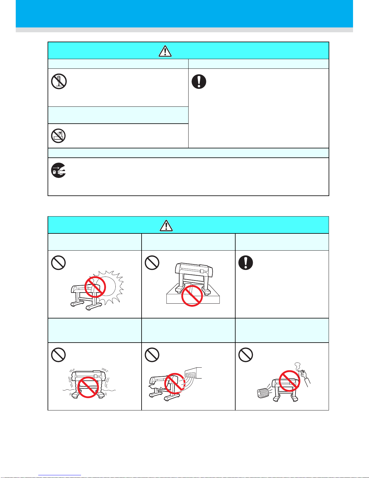
WARNING
Do not disassemble or remodel the plotter. Handling of the power cable
• Never disassemble or remodel the plotter.
Disassembly or remodeling can result in an
electric shock or breakdown of the
machine. Do not use the plotter in a damp
place.
• Use the supplied power cable. Take care
not to damage, break or work upon the
power cable. If a heavy material is placed
on the power cable, or if it is heated or
pulled, the power cable can break, thus
resulting in fire or electric shocks.
Avoid locating the plotter in a damp
environment.
• Do not splash water onto the machine. Use
in such an environment can give rise to fire,
electric shocks or breakdown of the plotter.
In case abnormal event occurs.
• Use of the plotter under an abnormal condition where the device produces smoke or strange smell
can result in fire or electric shocks. If such an abnormality is found, be sure to turn off the power
switch immediately and unplug the cable from the wall outlet. Check first that the plotter no longer
produces smoke, and contact your distributor for repair. Never repair your plotter by yourself since it
is very dangerous for you to do so.
CAUTION
A place exposed to direct
sunlight
On an inclined surface A place where temperature or
humidity varies significantly
• Use the plotter under
the following
environmental
conditions:
Operating environment:
20 to 35°C
35 to 65% (Rh)
A place that vibrates A place exposed to direct air
flow from an air conditioner or
the like.
Around a place where flame is
used
Page 8
Safety Precautions
7
Safety Labels
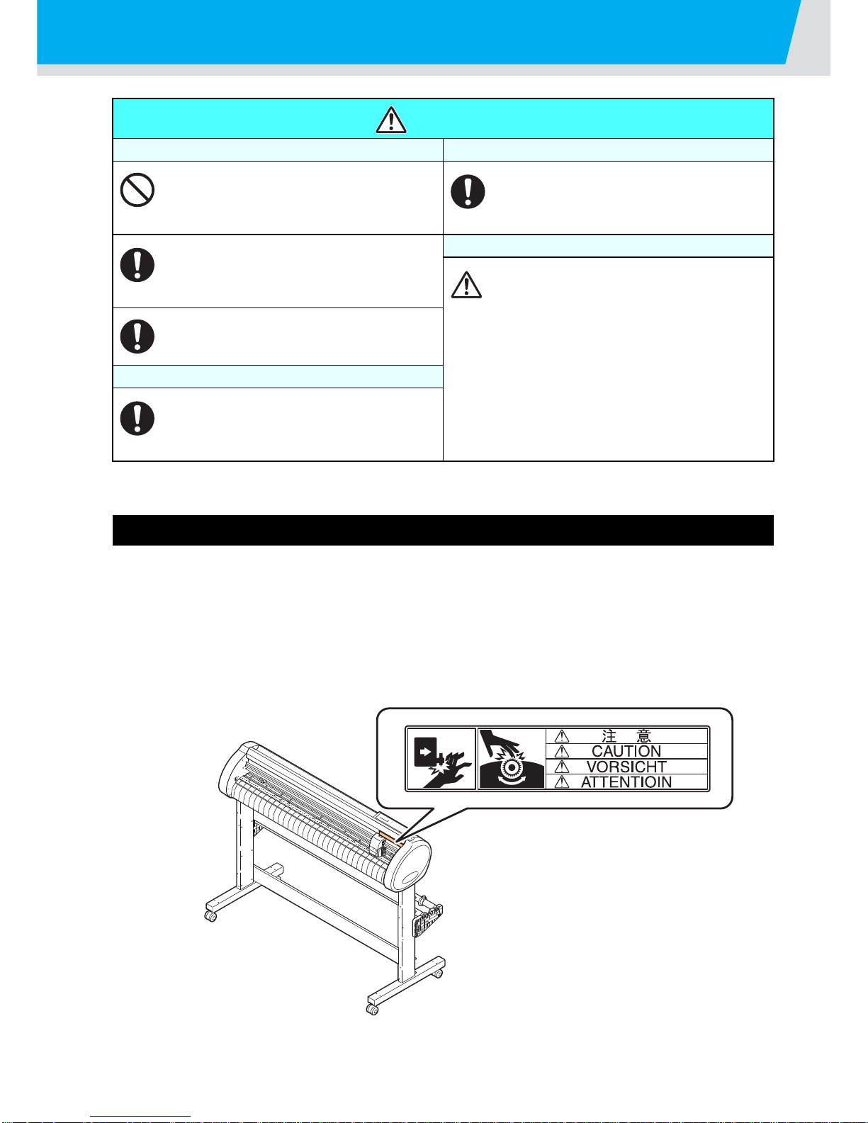
A safety label is stuck on the machine. The label informs the user of possible risks associated with the
machine.
Be sure to understand the correct meaning of the safety label to avoid danger.
If the safety label is illegible due to stains or has come off, purchase a new one from your local distributor or
our office. (Reorder: No.M904451, Safety label)
Depending on the manufacturing time, the label differs. When reordering the label, please ask for
M904451 as a order number.
CAUTION
Be careful with the movable parts Caution with cutters
• Do not touch the rolling grit roller;
otherwise, you may hurt your fingers or tear
off your finger nails.
• Do not touch the cutter blade, which is very
sharp.
• Do not shake or swing the cutter holder;
otherwise, the blade may come off.
• Keep your head and hands away from any
moving parts during cutting (plotting)
operation; otherwise, you may get your hair
caught in the machine or get injuries.
Caution with cutters
• Be sure to connect the ground wire.
Using without the ground wire ca uses the
damage of this device and electric shock
that may be very dangerous.
• Regarding the use of two polar plug outlet,
you must connect the auxiliary ground
adapter to the plug of power cable.
Earth the green wire (ground wire) of the
ground adapter. If you cannot, consult with
an electrician.
• Wear proper clothes. (Do not wear loose-fit
clothes or accessories). Bind a long hair.
Sheets
• Straighten the sheet of media, if
significantly curled, before using it for
printing. Heavily curled sheet affects the
cutting (plotting) result.
Page 9
8
CWhere to install this machine
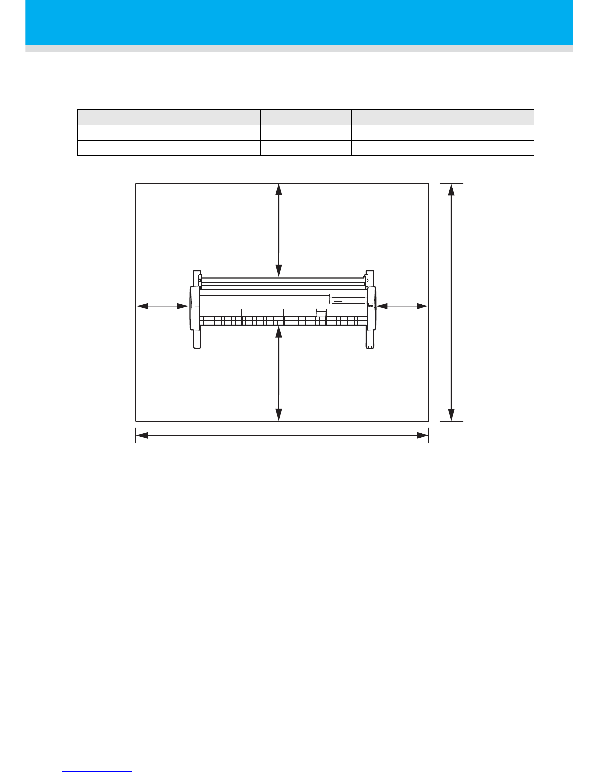
Secure a suitable installation space before assembling this machine.
The place of installation must have enough space for not only this machine itself but also for printing
operation.
Model Width Depth Height Gross weight
CG-100SRII 1435 mm 580 mm 1125 mm 38 kg
CG-130SRII 1735 mm 580 mm 1125 mm 44 kg
CG-100SRII : 2435 mm
CG-130SRII : 2735 mm
500 mm
or more
500 mm
or more
1000 mm or more
1000 mm or more
2580 mm
or more
Page 10
9
Configuration and function
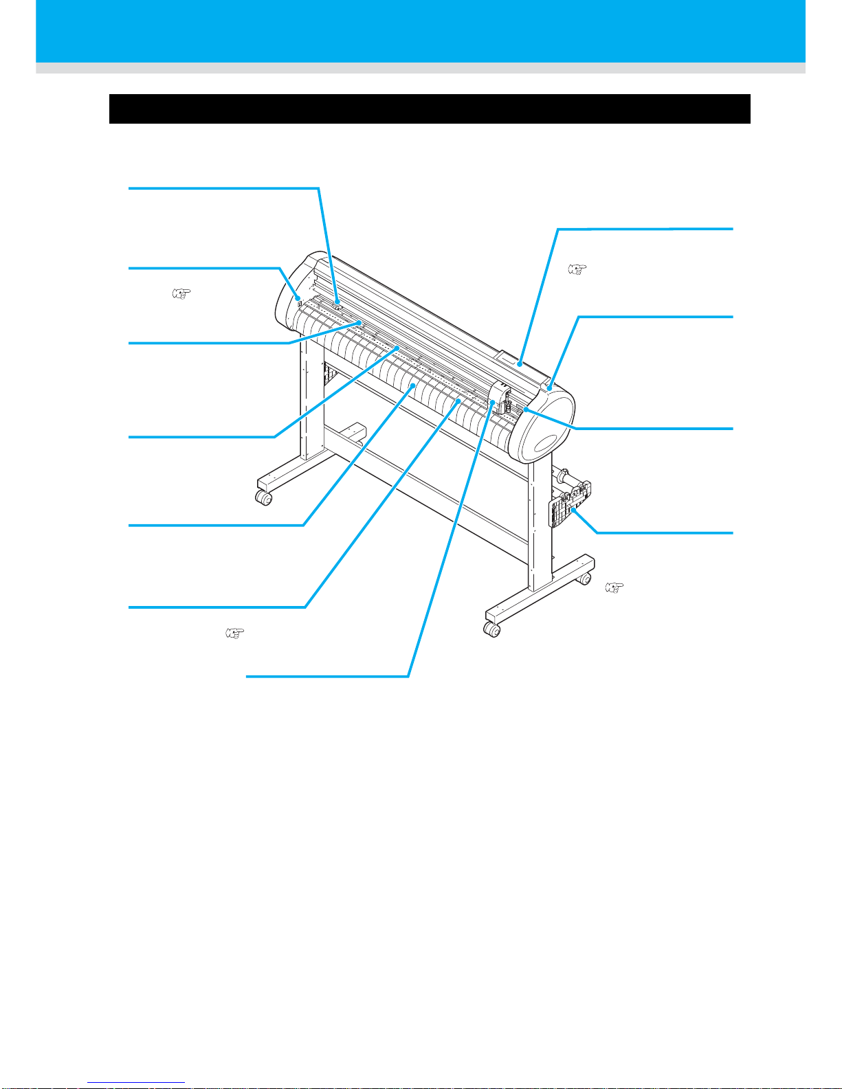
The Front
Carriage
The carriage carries the
pen and moves it up and
down.
Power switch
The switch turns on/off the
power.( P.19, P.35)
Grit roller
The grit rollers operate in
combination with the pinch
rollers to feed the sheet.
Platen
The sheet of media moves
along the platen.
Operation panel
This panel operates this
machine and sets functions.
(P.11)
Clamp lever
Pushing a lever down
lowers a pinch roller and
retains the sheet.
Pinch roller
The pinch rollers feed out the
sheet while pressing it against
the grit rollers.
Pen line
The plotter performs cutting or plotting on the pen
line.
Pinch roller guide mark
This marks indicate the
locations at which the
pinch roller are to be set.
Roll stoppper
When setting a sheet,
prevents the roll sheet
from rotating.
( P.29)
Cut slot
The slot is used for cutting the
sheet manually.
(P.34)
Page 11
10
Configuration and function
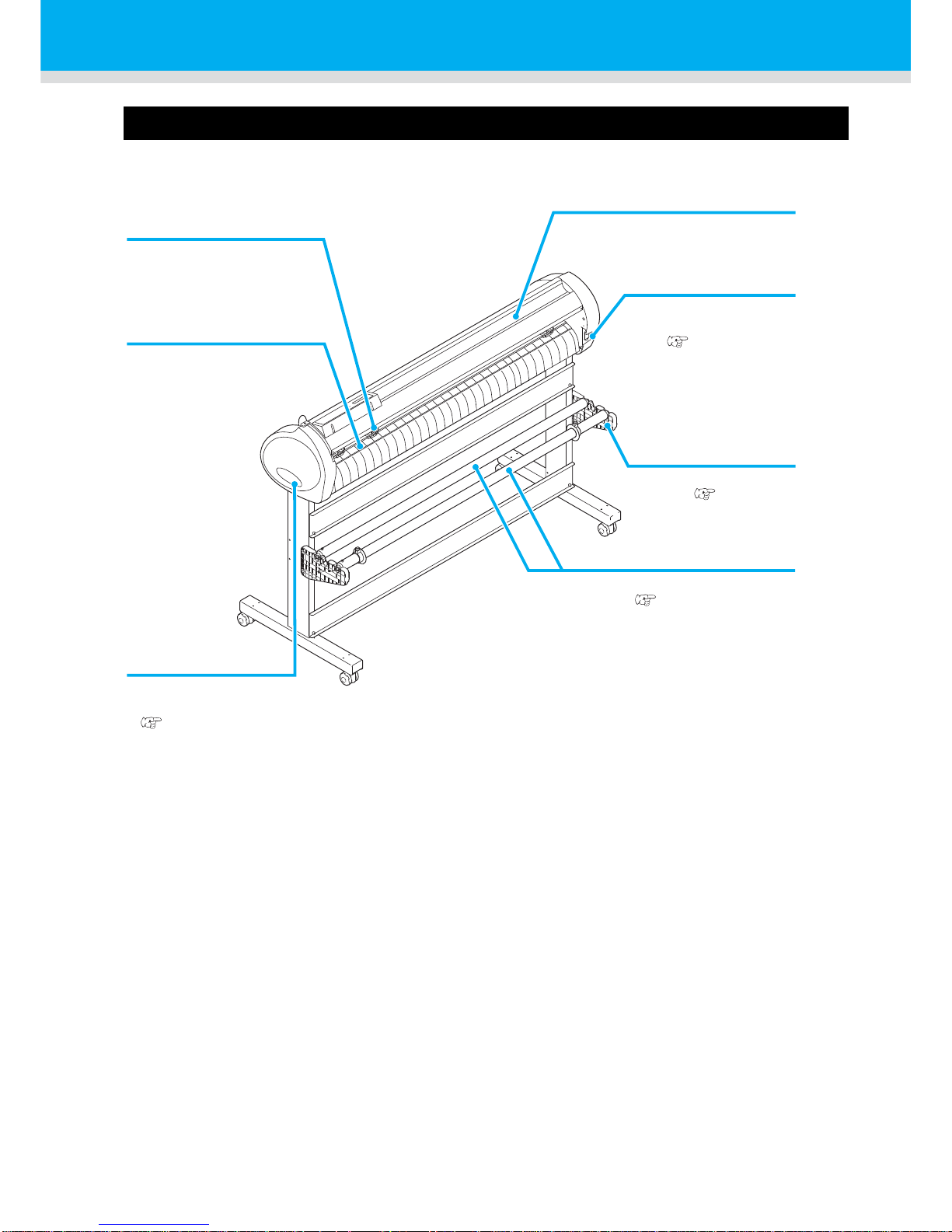
The Rear
Clamp pressure lever
This lever adjusts the force
by which the clamp is held.
Tray
Small tools, such as a retractable
knife and other cutters, can be
placed on.
Roll bar
A roll sheet is placed on the two
roll bars. ( P.28)
AC inlet
The power cable is
connected to the AC
inlet.( P.13)
Sheet sensor
This sensor detects the
presence of the sheet and
sheet length.
Roll stay
Roll stays support the
roll bars. ( P.28)
USB / RS-232C
interface connector
The USB and RS-232C
interface connector.
(P.12)
Page 12
Configuration and function
11
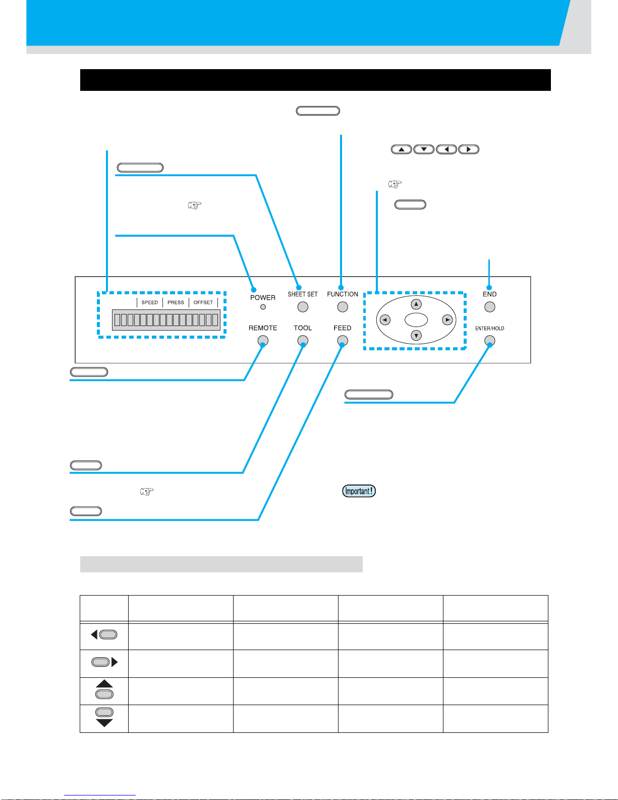
Operation Panel
Jog keys
The arrow keys are used as described in the table below.
In this manual, the sheets of media other than roll sheets are referred to as leaf sheets or cut sheets.
Before the detection
of a sheet
After the detection
of a sheet
When selecting a
function
When selecting a
setting value
Detects the sheet
width.
Shifts the carriage to
the left.
--
Detects the width and
length of the sheet.
Shifts the carriage to
the right.
--
Detects the sheet
width.
Move the sheet toward
the rear of the plotter.
1Restores the
previous function.
Selects the previous
value.
Detects the width and
length of the sheet.
Move the sheet toward
the front of the plotter.
Selects the next
function.
Selects the next
value.
key
This key switches the operation mode
between REMOTE mode and LOCAL mode.
If this key is pressed when the plotter is in
operation, the plotter will come to a halt.
Press the key again to restart the plotter,
REMOTE
key
Use this key to select a tool and establish
tool conditions. ( P.21)
TOOL
key
Press this key to execute sheet feeding.
FEED
key
This key registers the last input value as the
setting value or returns the setting menu to
the immediate lower level in the hierarchy.
Use the key to correct the drifting of the
sheet during cutting (plotting) operation.
ENTER/HOLD
Display panel
The display panel indicates tool conditions such as
speed, pressure and offset, tool coordinates,
functions and error messages.
POWER lamp
This lamp lights up when
the power to the plotter is
turned on.
key
Use this key for detection of the
sheet or clearing of the
detection result.( P.26)
SHEET SET
key
Use this key to enter function setting mode.
FUNCTION
JOG Key
Each of these arrow keys shifts the carriage or
sheet in the direction of the arrow or changes
settings.( P.11)
key
This key cancels the last input value or
returns the setting menu to the
immediate higher level in the hierarchy.
Use the key to detect only the sheet
width.
END
Press the keys with the fingers.
Pressing with a sharp blade or a
pointed thing may break the key.
Page 13

12
Connecting the cables
This plotter uses the USB and RS232C connector
for connection to the host computer.
USB Cable Connection
When connecting the USB cable, you must observe the followings.
Connecting USB driver
As for USB driver connection, refer to “USB Driver Installation Guide” in the FineCut supplied with this
machine
.
(1)Set the
supplied CD for FineCut into the disk drive.
(2)Click [CD-ROM Contents] on the menu.
(3)Open [usb11_installguid(en).pdf] for the plotter used in [Mimaki USB1.1 Driver] folder.
RS-232C Cable Connection
When you want to connect the RS-232C cable, you must observe the following notabilia.
• Connect or disconnect the connectors
carefully. Applying undue force to a
connector may damage the connector.
• Do not plug in or unplug any cable during data transferring.
• Follow the instructions on the LCD if the wizard is displayed when connecting the USB cable.
• When connecting the cables, turn off first the power to the device and that tothe host computer
which the power cable is to be connected.
• Do not plug in or unplug any cable during data transferring.
USB
RS-2332C
Page 14
Connecting the cables
13
Connecting the power cable
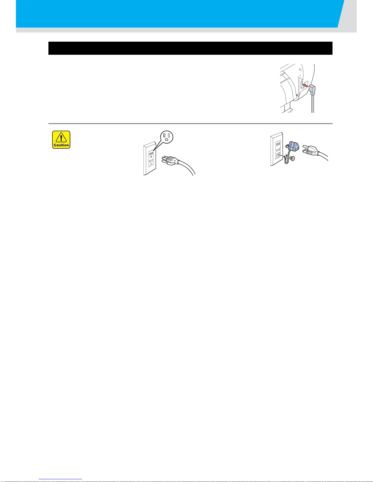
After connecting the interface cable, you must connect the power cable.
Connect the power cable with the plug outlet of the following power specifications.
•Voltage : AC100 - 240V ± 10%
• Frequency :50/60Hz
• Capacity : 145 VA or less
Be sure to connect
the ground wire.
• Using without the
ground wire
causes the
damage of this
device and electric
shock that may be
very dangerous.
Regarding the use
of two polar plug
outlet, you must
connect the
auxiliary ground
adapter to the plug
of power cable.
• Earth the green wire (ground wire) of the
ground adapter. If you cannot, consult with
an electrician.
Page 15
14
Operation flow
1
Installing a tool
2
Turning the power on
3
Setting the tool
conditions
4
Loading a sheet of media
5
Test cutting (plotting)
6
Cutting (plotting)
See "Installing a tool" ( P.15)
See "Turning the power on"
( P.19)
See "Setting the tool conditions"
( P.20)
See "Loading a sheet of media"
( P.23)
See "Test cutting (plotting)"
( P.31)
See "Cutting (plotting)" ( P.32)
7
Turning the power off
See "Turning the power off"
( P.35)
Page 16
15
Installing a tool
For this device, you can use the following tools.
Cutter : Select this to cut the image printed on a sheet and to create the cut letters with
the cutting sheet.
Pen (rollerball) : Select this to “trial-write” for confirming how to actually cut.
Pouncing Pin (option) : Select this to sketch the cut ting line.
Using a cutter
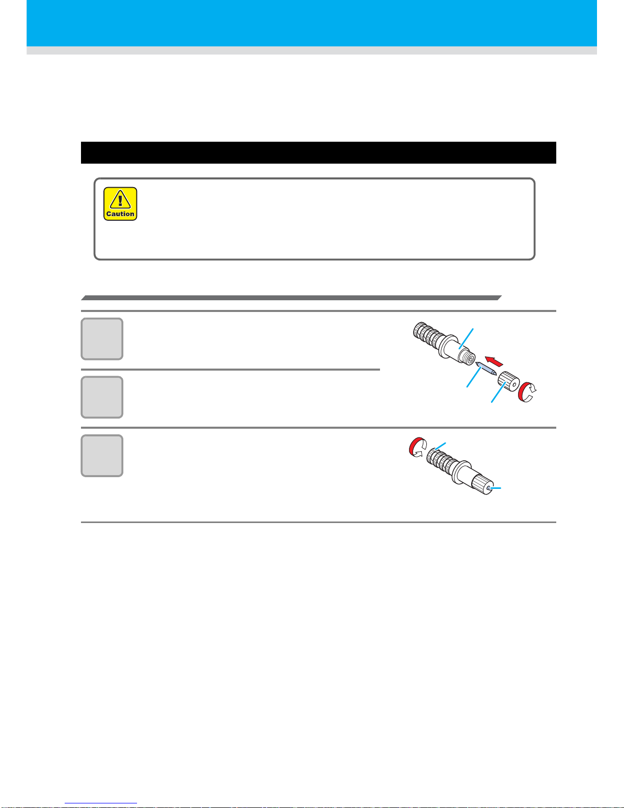
How to install a cutter
1
Remove the cap located at the edge by
rotating it.
2
Replace thecutter with a new one using
tweezers or the like.
3
Turn the adjusting knob to adjust the
protruding amount of the cutter.
• arrow to protrude the cutter blade.
( 0.5 mm per revolution)
• Don’t touch the cutter blade with your fingers.
->Sharp cutter tip may injure you.
• After setting the cutter, do not shake the cutter holder.
->The tip of the cutter may pop out and may injure you.
• Keep the cutter out of reach of children. Dispose of the used cutter blade in com pliance
with the applicable regulations.
Cutter holder
Cutter
Cap
Cutter
Adjusting knob
Page 17
16
Installing a tool
Adjusting the protrusion of the cutter blade
Adjust the cutter blade according to the types of the cutters and the sheet for use.
After adjusting the protrusion of the cutter blade, set the cutting conditions and conduct test cutting to check
the cutting quality.
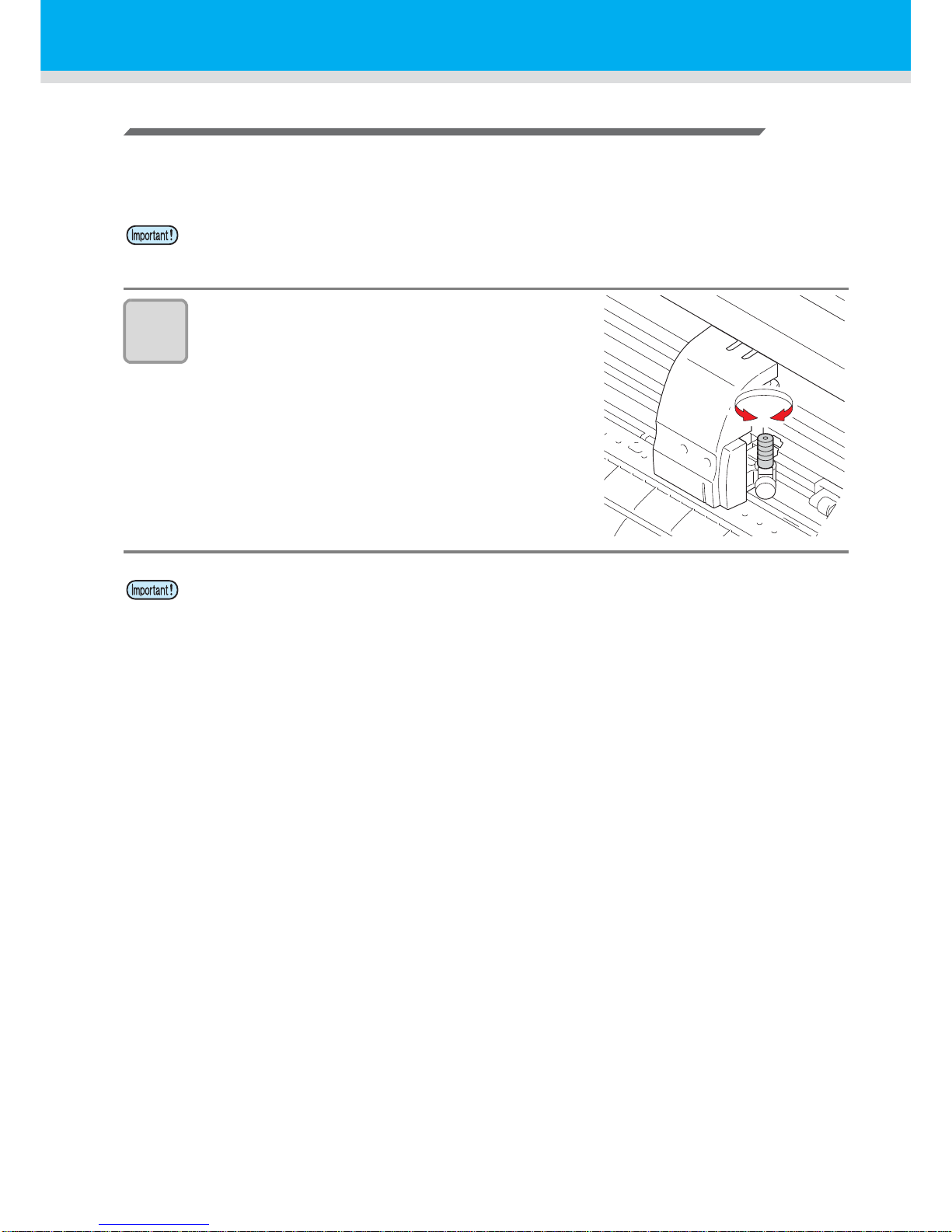
1
Turn the adjusting knob to adjust the
protruding amount of the cutter blade.
• arrow to protrude the cutter blade.
( 0.5 mm per revolution)
• Take care not to protrude the blade too much. If the cutter is used with its blade excessively
protruded, the cutter can cut out the base paper, thus damaging the main unit.
• See the operation manual for the blade adjustment of the cutters other than the auxiliary
products
Page 18
17
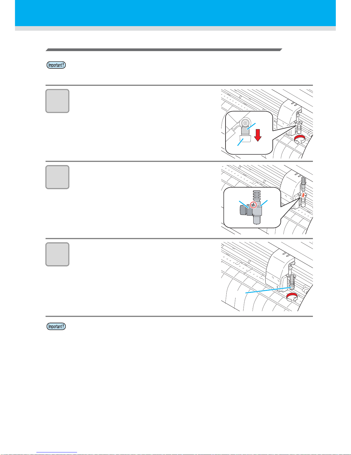
How to install the cutter
1
Rotate the knob to loosen the holder
presser.
2
Insert the cutter holder into the tool
holder.
• Push the brim of the cutter holder against the tool
holder.
• Press the brim of the cutter holder with the l holder
presser.
3
Fix the cutter holder.
• Turn the knob of the tool holder clockwise, and surely
fix it.
• Install the cutter to the tool holder of the carriage.Be sure to insert the cutter all the way in the
tool holder.
• Fix the cutter firmly. If not, accurate and high-quality cutting (plotting) will not be achieved.
Holder
presser
Knob
Brim
Holder
presser
Knob
Page 19
Installing a tool
18
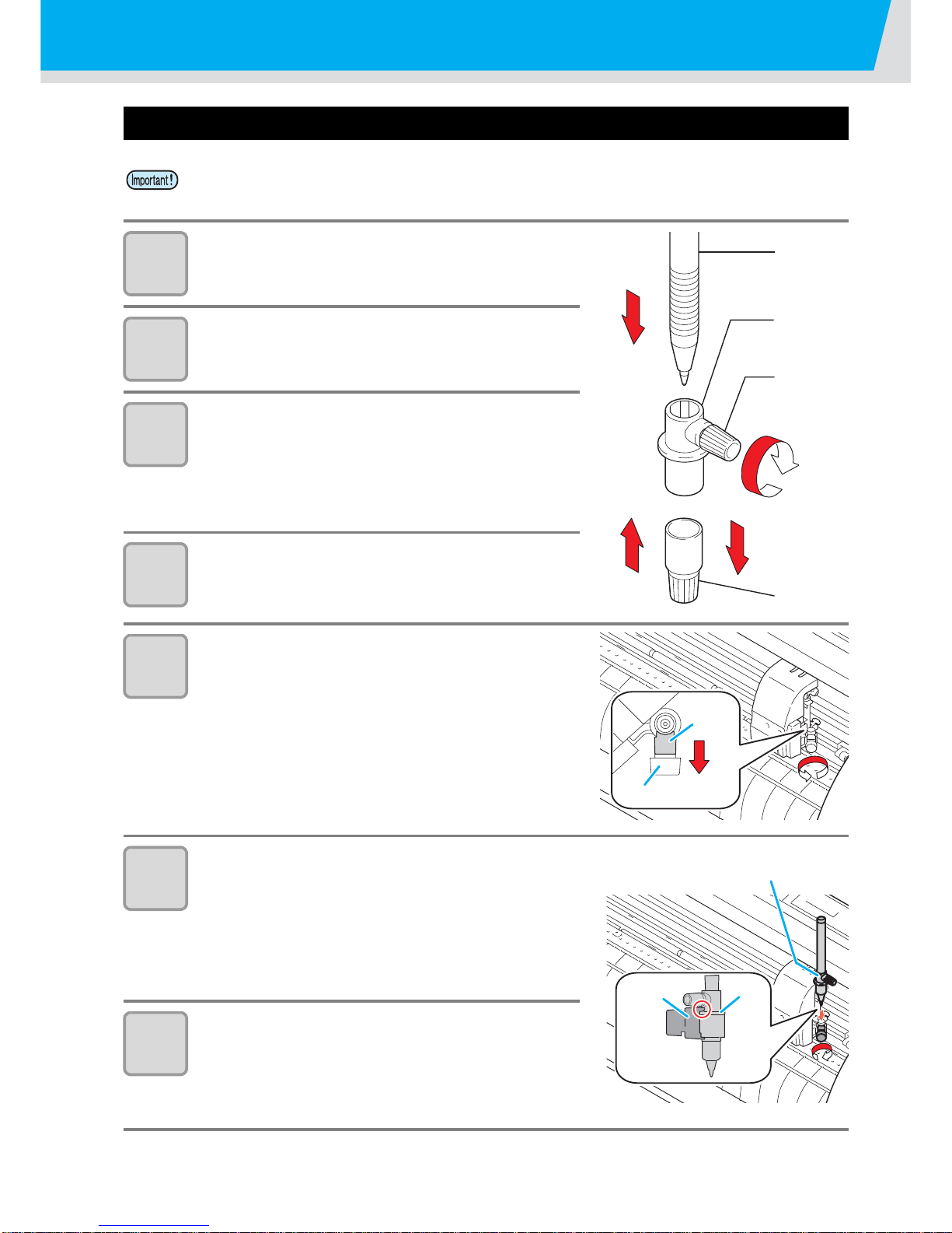
How to Install a Ballpoint Pen
1
Put the cap on the pen adapter.
• Use the cap to adjust the pen height.
2
Insert the pen into the pen adapter.
• Insert the pen until the pen head reaches the cap.
3
Fix the pen tip.
• Tighten the fixing screw clockwise.
• Be careful not to over-tighten the fixing screw for
the pen adapter. If tightened too much, the ballpoint pen may crack.
4
Remove the cap.
5
Rotate the knob to loosen the holder
presser.
6
Insert the pen adapter with the pen into
the tool holder.
• Make sure that the collar of the pen adapter is
rested on the holder.
• Set the adapter in such a way that the fixing screw
will not obstruct operation.
7
Turn the knob of the tool holder
clockwise to fix the tool.
• When use a boll-point pen on the market, refer to the oeration manual and select a installable
boll-point pen.
1
2
4
3
Pen
Pen adapter
Screw
Cap
Holder
presser
Knob
Insert until
it is rested
Holder
presser
Brim
Page 20
19
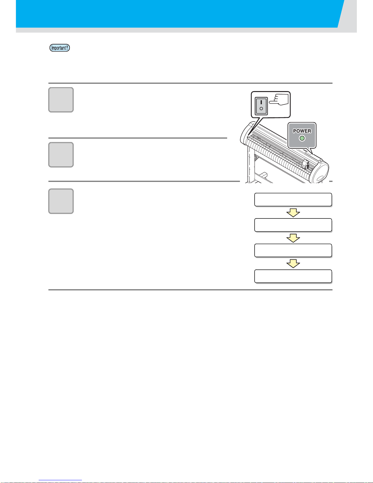
Turning the power on
1
Press the “ | ” side of the power switch.
• When the plotter is turned on, it will enter the first
operation mode, which are followed by the
subsequent modes. Refer to page 1-15 for the
operation modes.
2
The POWER indicator lamp lights up
green.
• The sheet suction fan rota tes.
3
Check the receiving buffer.
• Then, the tool conditions for the currently selected
tool appears on the LCD.
• Before turning the power on, check that the pinch rollers have been raised.
• Be sure to turn on the host computer before turning on the plotter. If this order is not correctly
followed, the plotter can malfunction.
• Once the power is turned off, wait at least five seconds before turning the power on again.
BOOT
CG I I c - 6 0 R * . * *
BUFFER=30720KB
CUT1 20 050 0.30
Page 21
20
Setting the tool conditions
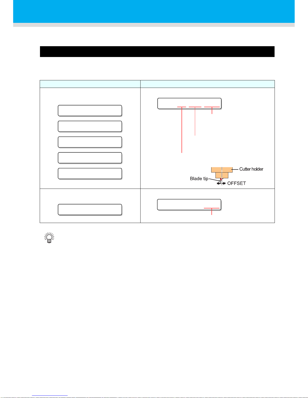
You must set the tool conditions adjusting to your use.
Kinds of the Tool Conditions
The kinds of the tool conditions include cutting and plotting conditions .
See P.20 for the way of setting tool conditions.
Kinds Description
Cutting Condition (CUT1 ~ CUT5)
This is the tool conditions for using the cutter.
Plotting Condition (PEN)
This is the tool conditions for using a pen.
• Besides the above list, able to set the cutting condition for "POUNCHING" and "HALF CUT".
Refer to the operation manual for more detail.
CUT1 20 050 0 .30
CUT2 20 080 0 .30
CUT3 05 150 0 .30
CUT4 20 060 0 .30
CUT5 20 070 0 .30
CUT1 20 050 0.30
OFFSET
The distance from the center
of the cutter holder to the
cutter blade
PRESSURE
The pressure required
for cutting
SPEED
The speed of cutting
PEN 40 080
PEN 40 080
You need not to set OFFSET.
Page 22
21
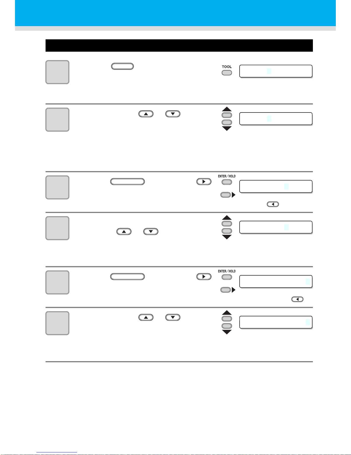
Set the Tool Conditions.
1
Press the key several times to
select a tool condition for setting.
• Refer to P.20 for selectable tool conditions
• Select [CUT2] here.
2
Press the jog key or to
change the SPEED value.
• The setting values :1 to 10cm/s (settable by 1cm/s step)
15 to 60cm/s (settable by 5cm/s step)
• Increase the value, and you get the higher speed. Decrease the value, and you get the
lower speed. (Set 20 to 30cm/s regularly).
• When [HEAVY] is set on [SHEET TYPE], the maximum cutting speed is limited to 20cm/s.
3
Press the key or jog key
to move the cursor to PRESSURE.
• When you want to return to the previous setting item, press the jog key .
4
Change the value of PRESSURE using
the jog key or .
• The setting values :10 to20g (settable by 2g step)
20 to 100g (settable by 5g step)
100 to 400g (settable by 10g step)
5
Press the key or jog key
to move the cursor to OFFSET.
• When you want to return to the previous setting item, you must press the jog key .
6
Press the jog key or to
change the value of OFFSET.
• The setting values :0.0 to 2.5mm (settable by 0.05mm step)
• If you have selected the POUNCING condition (PIN) in the Step 1, you must set the
pounce interval here. (The setting value: 1 to 100mm (1mm step))
CUT 2 20 080 0.30
TOOL
CUT 2 50 080 0.30
CUT2 50 0800.30
or
ENTER/HOLD
CUT2 50 1000.30
CUT2 50 100 0.30
or
ENTER/HOLD
CUT2 50 100 0.35
Page 23

Setting the tool conditions
22
7
Press the key or
jog key to secure the setting
value.
• After setting the tool condition, execute test cutting. ( P.31)
• When you set PRESSURE to lower than 20g in the Step 4, you must set the setting of SPEED
to lower than 10cm/s in the Step 2. Otherwise, the setting may cause the tool to be lifted, and
blurred plotting as well as undone cutting.
• Don’t perform cutting adjustment only with the protruding amount of the cutter edge while
PRESSURE (cutting pressure) remains to be set hard. If cutting is made with the less
protruding amount of the cutter edge but with stronger PRESSURE, strange sound may come
out during cutting. In addition, the bottom of the cutter and the sheet scrape each other, which
may cause the sheet surface to have scratches and which may lower th e cutting quality.
CUT2 50 100 0.35
or
ENTER/HOLD
Page 24
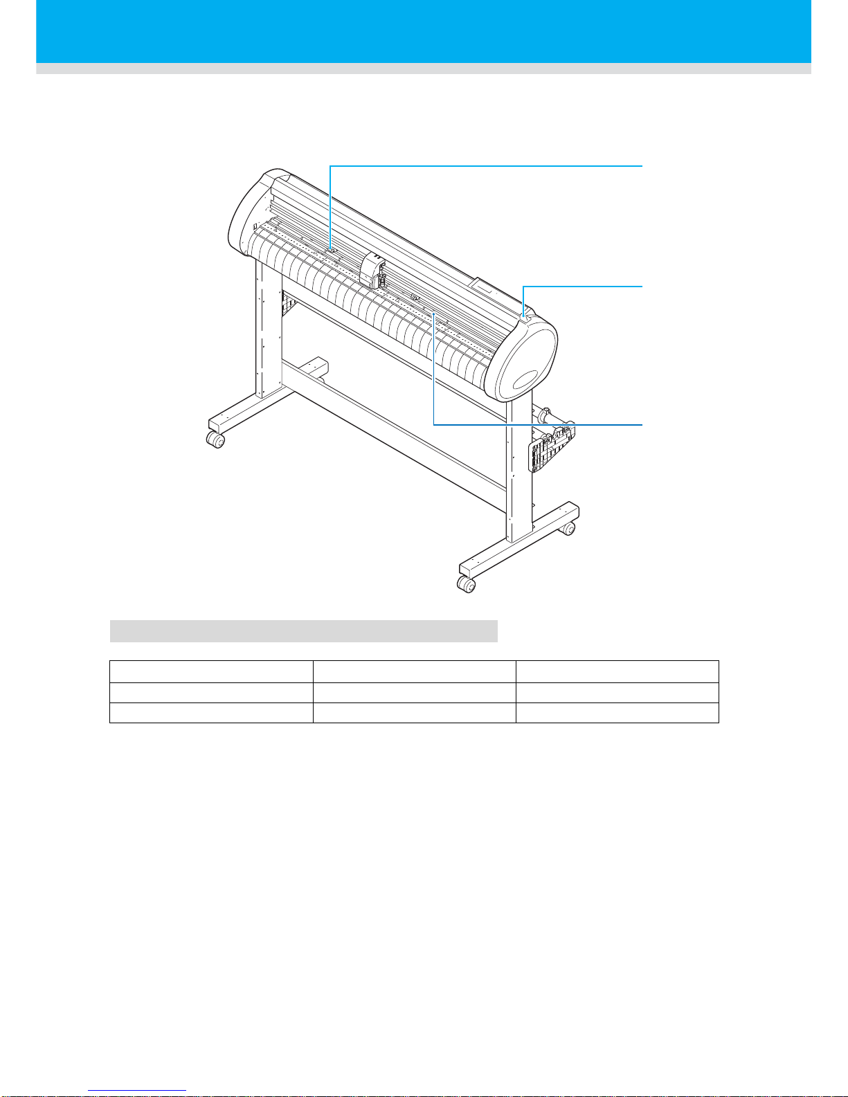
23
Loading a sheet of media
Either a leaf sheet (cut sheet) or a roll sheet can be loaded on the plotter.
The pinch rollers and grit rollers hold the sheet in position.
Locate the pinch rollers so that they match the sheet to be used.
Sheet width available
mm inch
CG-100SRII 90 to 1250 3.55 to 49.20
CG-130SRII 90 to 1550 3.55 to 61.00
Pinch roller
Clamp lever
Grit roller
Page 25
24
Loading a sheet of media
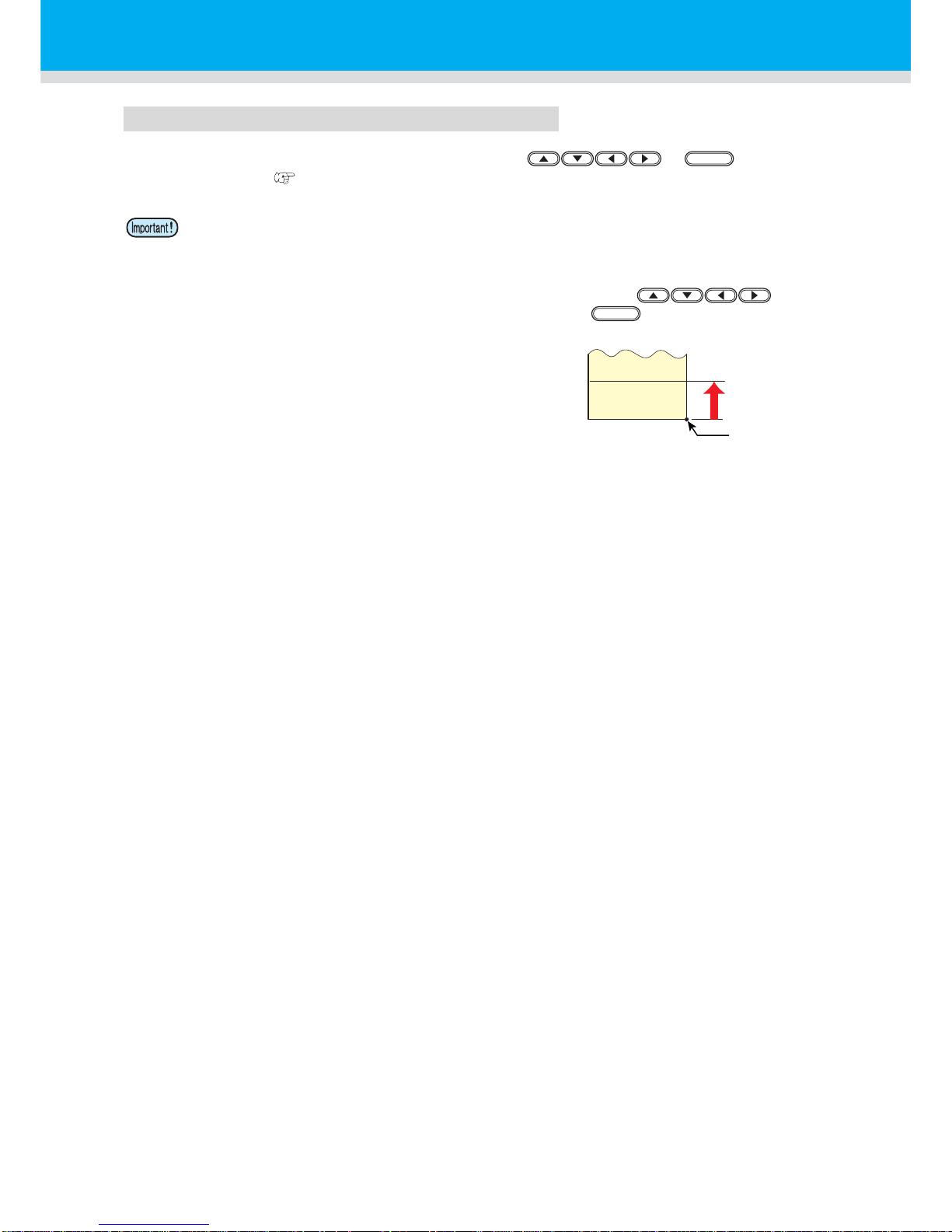
Sheet detection
The width and length of the sheet are detected by pressing or key depending
on the sheet loaded. ( P.25)
• Once the sheet length has been detected, if the received data is larger than the sheet, the
portion of data that exceeds the sheet cannot be used for cutting.
If the sheet length is not detected, the plotter will terminate cutting operation when data goes
beyond the sheet.
• If the sheet sensor function is set to [OFF], a press of a jog key will make
the plotter perform the same sheet detection as the case key is pressed. (Only the
sheet width is detected.)
• The maximum length that can be detected at the
front and rear ends of the sheet of media is 3 m.
END
END
Origin after
detection
3 m maximum
When the tail end of
the sheet is detected
Page 26
25
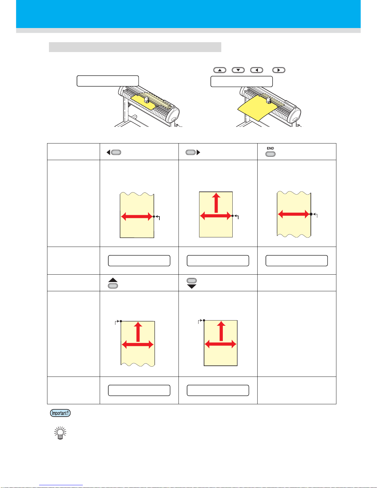
Method of detecting a sheet
When a sheet of media is set, the following two displays will appear alternately on the LCD panel.
Align to the direction of the set sheet, and press the jog keys , , or .
The plotter uses the five different methods to detect a sheet of media as shown below.
Key
Sets the roll sheet
in the back.
Sets the leaf sheet
in the back.
Detects only the
sheet width.
Detecting
method
The sheet width is
detected.
Front side of the plotter
After the sheet width is
detected,The back end of
the sheet is detected.
Front side of the plotter
The sheet width is
detected.
Front side of the plotter
Example of
display after the
sheet detection
Key
Sets the roll sheet in
the front.
Sets the leaf sheet
in the front.
Detecting
method
After the sheet width is
detected, the back end of
the sheet is detected.
Front side of the plotter
After the sheet width is
detected,the back end of
the sheet is detected.
Front side of the plotter
Example of
display after the
sheet detection
• When the detected length is 3 m or more, the display “ **** ” will appear on the LCD.
• When a long sheet of media is used or a sheet which has already been drawn out is used from
its middle area, the sheet detection will require an extended period of time. In such a case, the
detection time can be reduced by detecting only the sheet width.
R set
A sheet is set from
the rear side.
F set
A sheet is set from
the front side.
ROLL < R > L EAF
ROL L F LEA F
<
>
B
Origin
A
B
Origin
B
Origin
A=**** B=123
A=567 B=123
A=**** B=123
A
B
Origin
B
A
Origin
A=**** B=123
A=567 B=123
Page 27
26
Loading a sheet of media
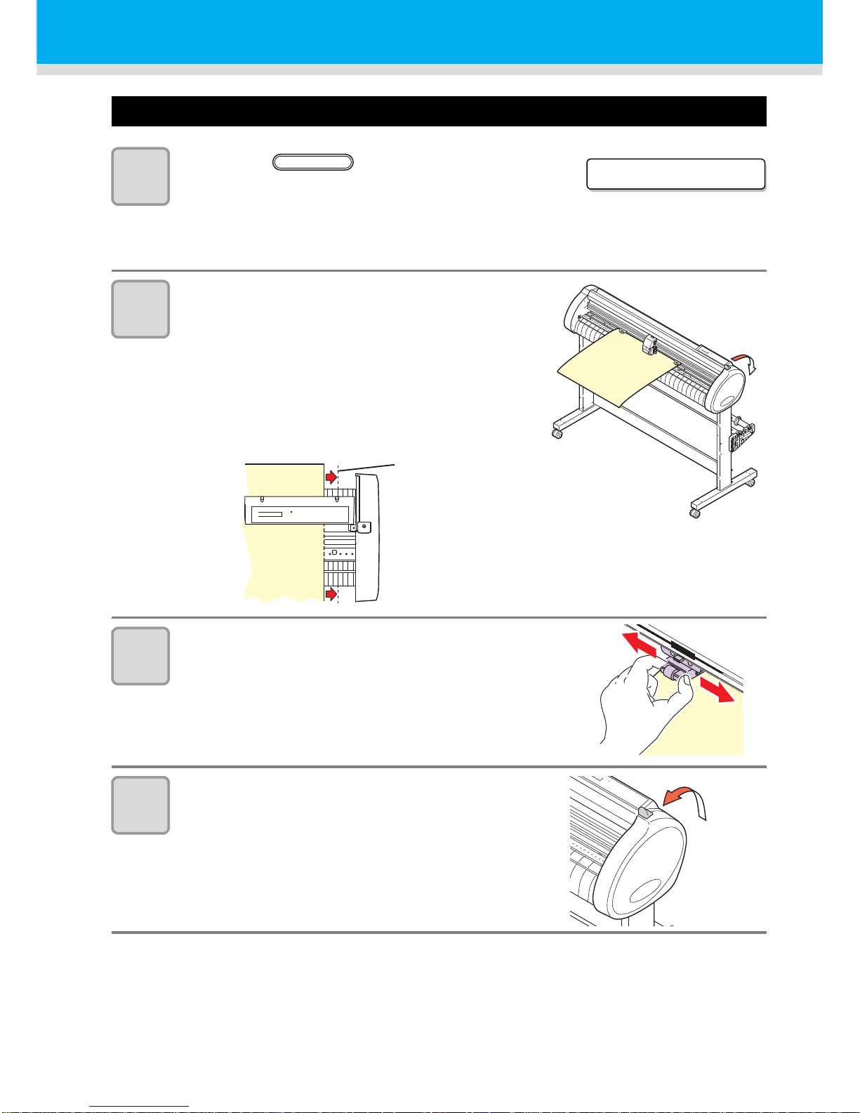
Loading a leaf sheet (cut sheet)
1
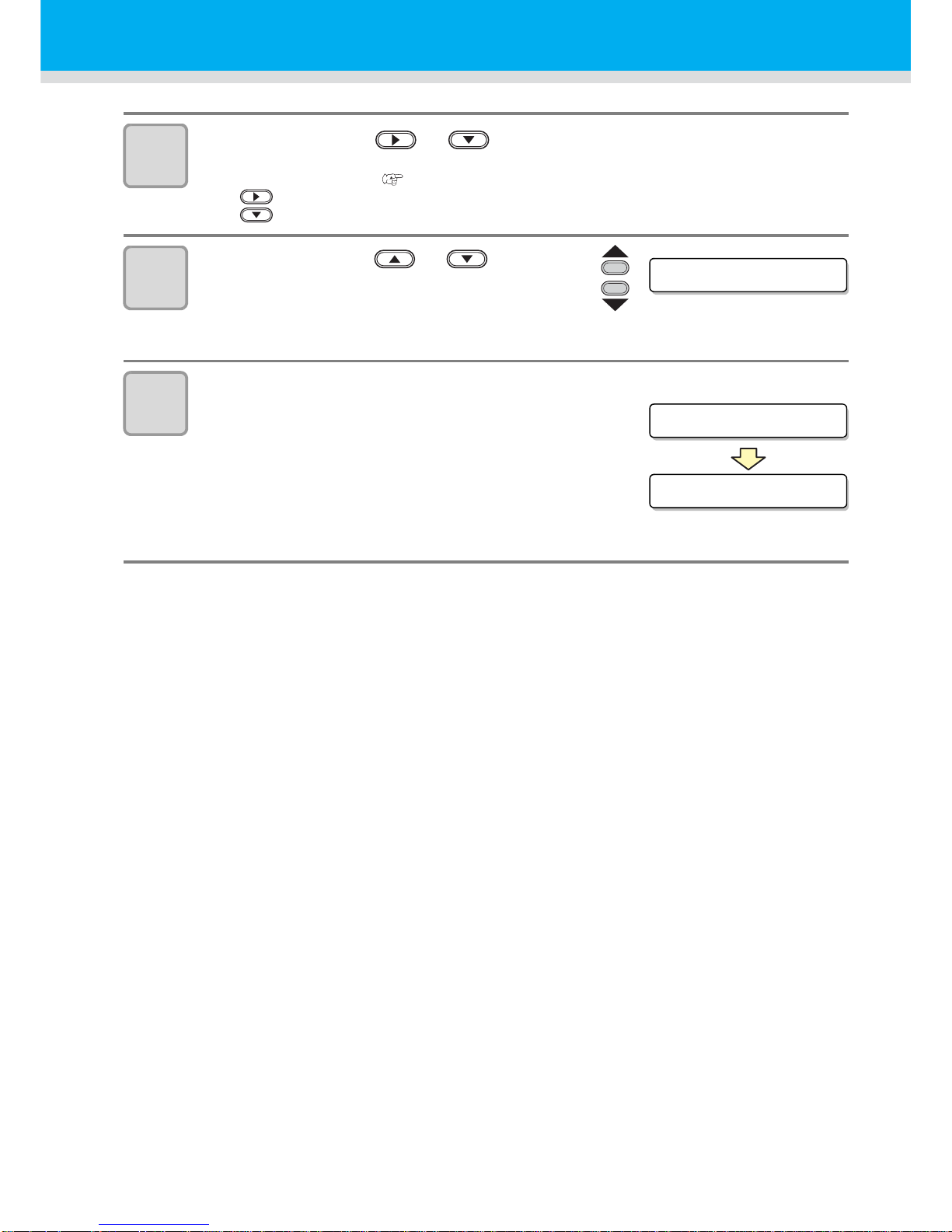
Press the key to switch to
NOT READY mode.
• You need not to do so if it’s already in the NOT
READY mode.
Start operation from the Step 2.
2
Load the leaf sheet on the platen.
(1) Move down the clamp lever to the rear and raise the
pinch rollers.
(2) Set the right end of the she et considering the platen
vertical rib as the measure.
Or, align the near end of the sheet in parallel with the
platen.
3
Move the pinch rollers so that they suit
the sheet width.
• Locate each of the pinch rollers 5 mm or more
inside the sheet edge; otherwise, the sheet can
slip off the pinch rollers while it is being fed.
4
Move down the clamp lever to the front
and move the pinch rollers down.
ROL L < R > LEA F
SHEET SET
Vertical rib
Page 28
27
5
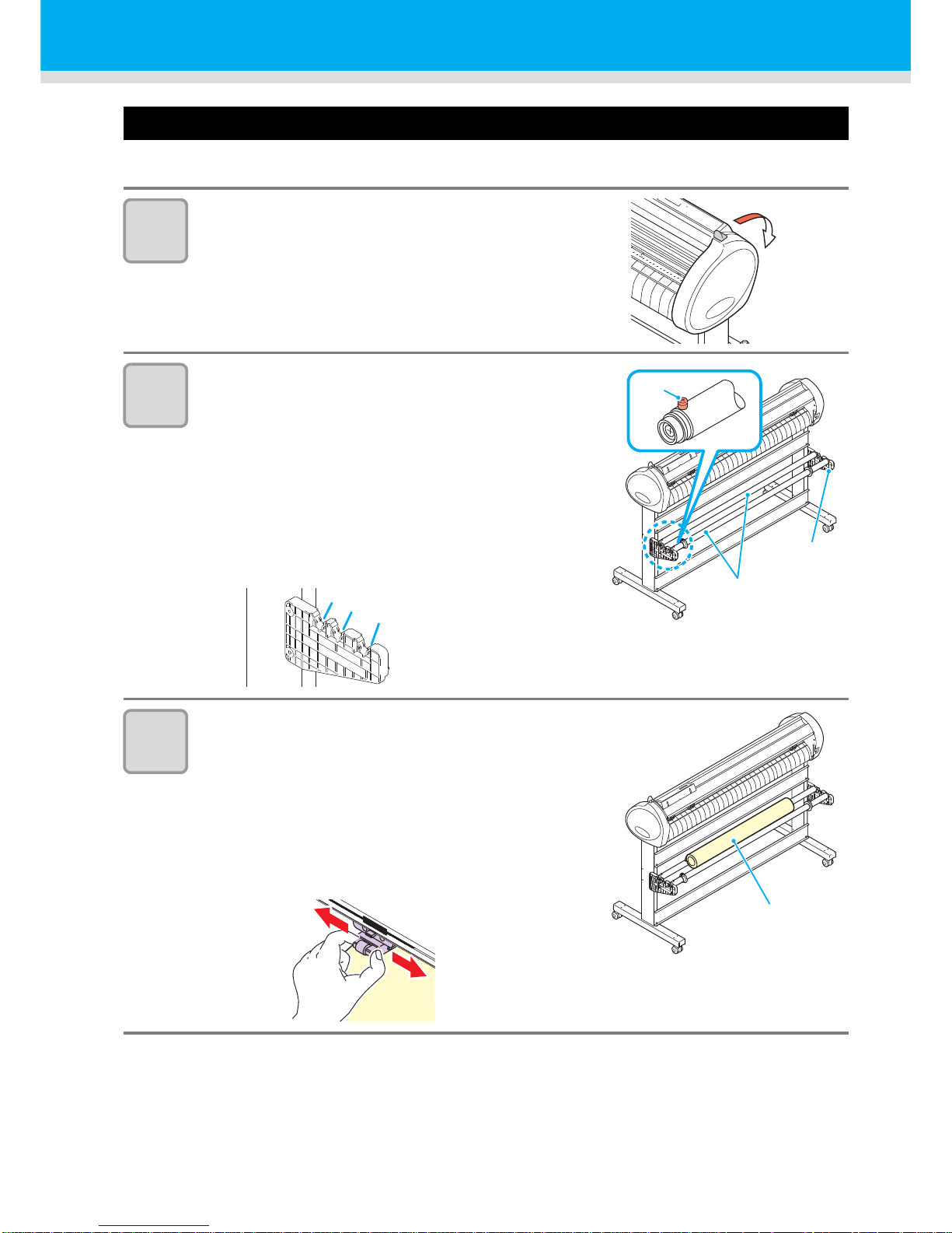
Press the jog key or to select “LEAF”.
• "Sheet detection" ( P.24)
• : In the case the sheet is loaded from the rear
: In the case the sheet is loaded from the front
6
Press the jog key or to select
number of pinch rollers to be used.
• When [ROLL. SELECT] is set to [ON], selectthe
number of pinch rollers to be used.
7
Start detecting the sheet.
• When [DUMMY CUT] is set to [ON], after completing the
sheet detection, the plotter performs dummy cutting
operation.
• This plotter cannot detect the discard sheet of
longer than 3m.
PINCH ROLL.:3
A=654 B=459
CUT1 20 050 0.30
Unit : mm
Displays the detected
size of the leaf sheet.
Displays the current
settings of tool conditions.
Page 29
28
Loading a sheet of media
How to Place the Roll Sheet
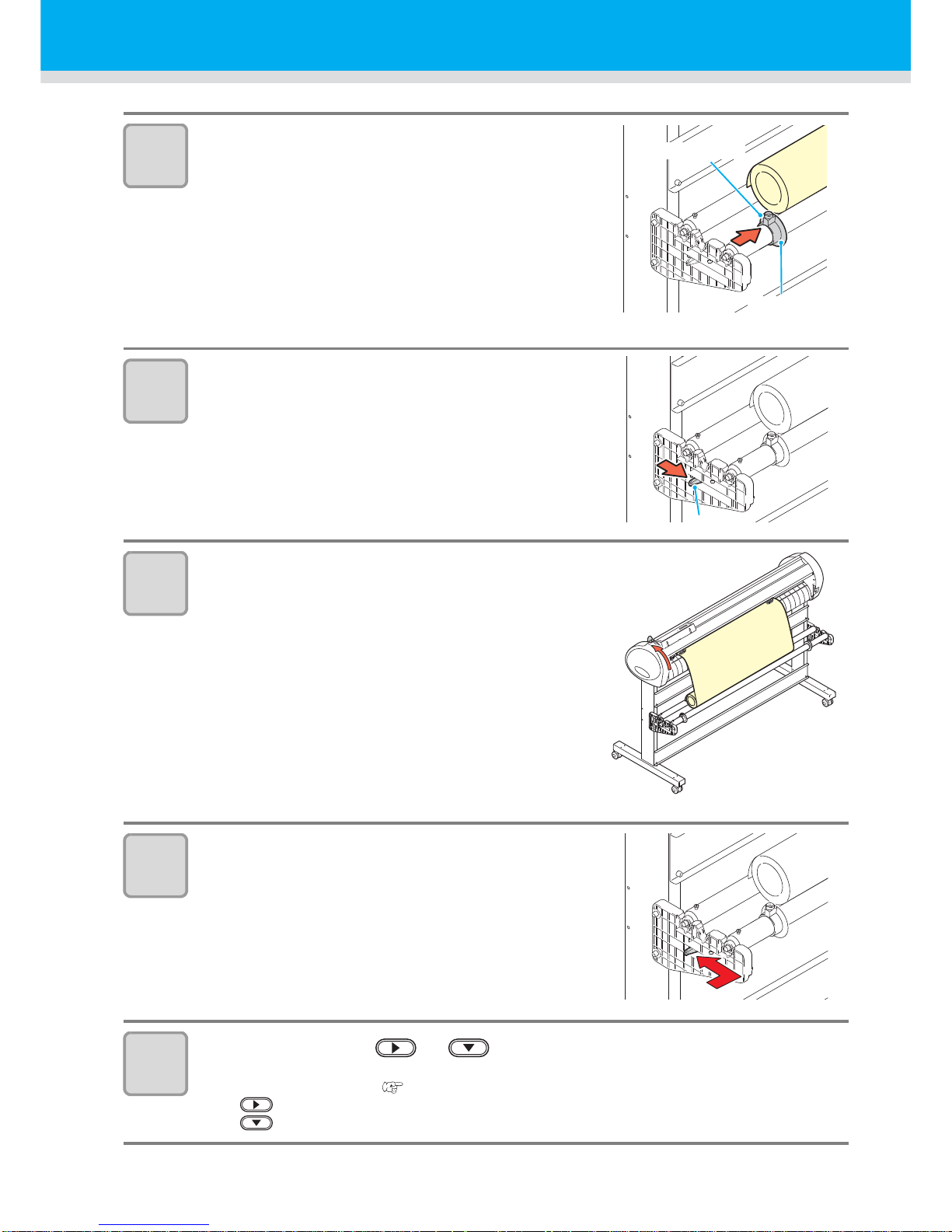
If you want to use the roll sheet, you must mount the roll-placing table.
1
Move down the clamp lever to the rear.
2
Set the roll bars on the roll stays.
• Set each roll bar so that the side providedwith a
projection is located on the left side asviewed from
the rear of the plotter.
Select the groove 1 or 2 to set one of the rollbars
depending on the outside diameter of theroll sheet to
be used.
• If the outside diameter of the rollsheet is 3 inch or
more, place theroll bars in the grooves 1 and 3.
• If the outside diameter of the rollsheet is less than 3
inch, place theroll bars in the grooves 2 and 3.
3
Load a roll sheet.
(1) Place a roll sheet on the roll bar s.
(2) Pass theleading edge of the sheet onto the platen
andadjust the location of the pinch rollers to thesheet
width.
• Locate each of the pinch rollers 5 mmor more
inside the sheet edge; other-wise, the sheet can
slip off the pinchrollers while it is being fed.
Roll bar
Rollstay Assy
Projection
1
2
3
Roll sheet
Page 30
29
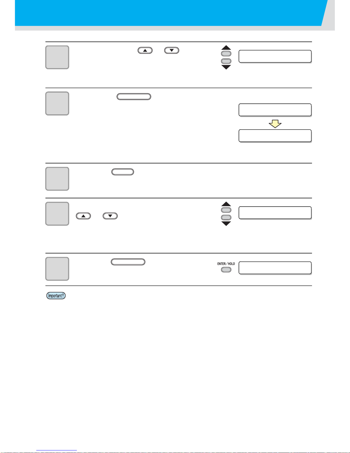
4
Retain the roll sheet with the roll
holders.
• Move the roll holders to both ends of the
roll,respectively, and secure them by tighteningthe
screws.
• Locate the roll holders 2 to 3 mmaway from the
respective roll ends.If the roll holders are fixed
pressedagainst the roll ends, there may be acase
where the roll cannot turn andthus the sheet cannot
be feed.
5
Lock the roll stopper.
• Push the lock lever toward the rear of themain unit to
lock the stopper.
• The roll stopper prevents the rollfrom turning when
you draw out thesheet.
6
Hold the sheet.
(1) Pull the sheet to take up the slack in it.
(2)
Check that the sheet is set without slacks and then move
down the clamp lever to the front.
• If the plotter has been turned on:The suction fan will
rotate to retainthe sheet by suction.
• If the plotter has been turned off:
The suction fan will not rotate. It is,therefore,
necessary to tilt the clamplever toward the front of the
unit whileretaining the sheet with your lefthand to
prevent the sheet from warp-ing.
7
Release the roll stopper.
• Push and pull the stopper to the front of the plotter.
• If you do not release the roll stopper,the buzzer
sounds during sheetfeeding and the plotter stops.
8
Press the jog key or to select “LEAF”.
• "Sheet detection" ( P.24)
• : In the case the sheet is loaded from the rear
: In the case the sheet is loaded from the front
Do not place
too near
Roll holder
Rock
Release
Page 31
Loading a sheet of media
30
9
Press the jog key or to select
number of pinch rollers to be used.
• When [ROLL. SELECT] is set to [ON], selectthe
number of pinch rollers to be used.
10
Press the key to start to
search the sheet.
• After the sheet width is displayed, dummy cut will be
performed.
11
Press the key to pull out the sheet of the length you want to
use.
12
Input the feed amount using the jog key
or .
• Setting value
In “mm” : 0.1 m to 51.0 m (in increments of 0.1 m)
In “inch” : 1 to 167 feet (in increments of 1 ft.)
13
Press the key.
• The sheet will be fed by the input length.
• Before you use the roll sheet, previously pull out the sheet of the length you use to make
enough room. By feeding out the sheet, you can verify if there is any sheet misalignment or
not.
PINCH ROLL.:3
A=* * ** B=559
CUT1 20 050 0.30
Unit : mm
Displays the detected
size of the leaf sheet.
Displays the current
settings of tool conditions.
ENTER/HOLD
FEED
SHEET FEED: 10 .0m
SHEET FEED: 8 . 0m
ENTER/HOLD
Page 32
31
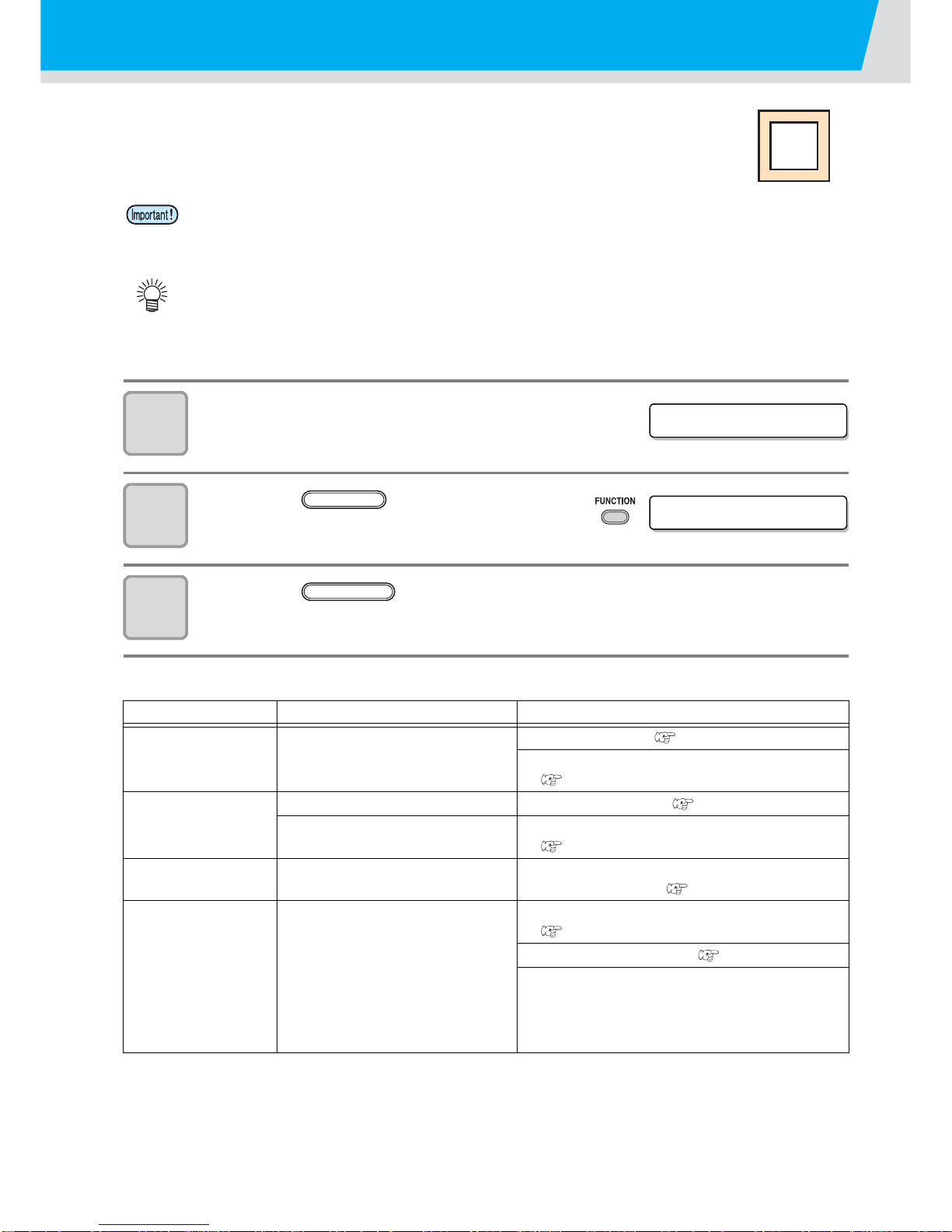
Test cutting (plotting)
Execute test cutting (plotting) to confirm the tool conditions.
In the test cutting, the plotter cuts two squares.
1
Confirm that the plotter is in the local
mode.
2
Press the key a few times to
select [SQUARE CUT].
3
Press the key .
• The plotter will execute test cutting (plotting) and then return to the local mode display.
Change the settings of the cut conditions according to the test cutting (plotting) results.
• When the cutter blade is worn and dull, you can use it temporarily by enhancing the value of
PRESSURE. However, you are recommend ed to replace the worn cutter blade with a new one
to ensure a satisfactory cutting quality.
• When the tool conditions are proper, the results of test cutting (plotting) are as follows:
The two squares are cut perfectly.
The base sheet remains uncut.
No corner of the squares is round.
No corner of the squares is curled-up.
Cut Condition Cause Remedy
Some parts uncut.
The blade is lifted above the
sheet because of a too high
cutting speed.
Lower the speed. ( P.21)
Tighten up the thumbscrew for the tool holder.
( P.17)
The base sheet has
been cut.
Too high pressure. Lower the pressure. ( P.21)
Too large protrusion of the cutter
blade.
Adjust the protrusion of the cutter blade.
( P.16)
Any of the square
corners rounded.
Improper OFFSET value.
Adjust the OFFSET value so that it suits the
cutter blade in use. ( P.21)
Any of the square
corners curled-up.
•The protruded cutter blade is
too much.
•The cutting pressure is higher.
•The [COMPENSATION
PRESSURE OFFSET value] is
large.
More than two out of the above
fall under this category.
Adjust the protrusion of the cutter blade.
( P.16)
Adjust the cut pressure. ( P.21)
Adjust the ADJ-PRS OFS value
CUT1 20 050 0.30
SQUARE CUT <ENT>
FUNCTION
ENTER/HOLD
Page 33
32
Cutting (plotting)
You can start cutting (plotting) after completion of setting up a tool, loading a sheet and setting the tool
conditions.
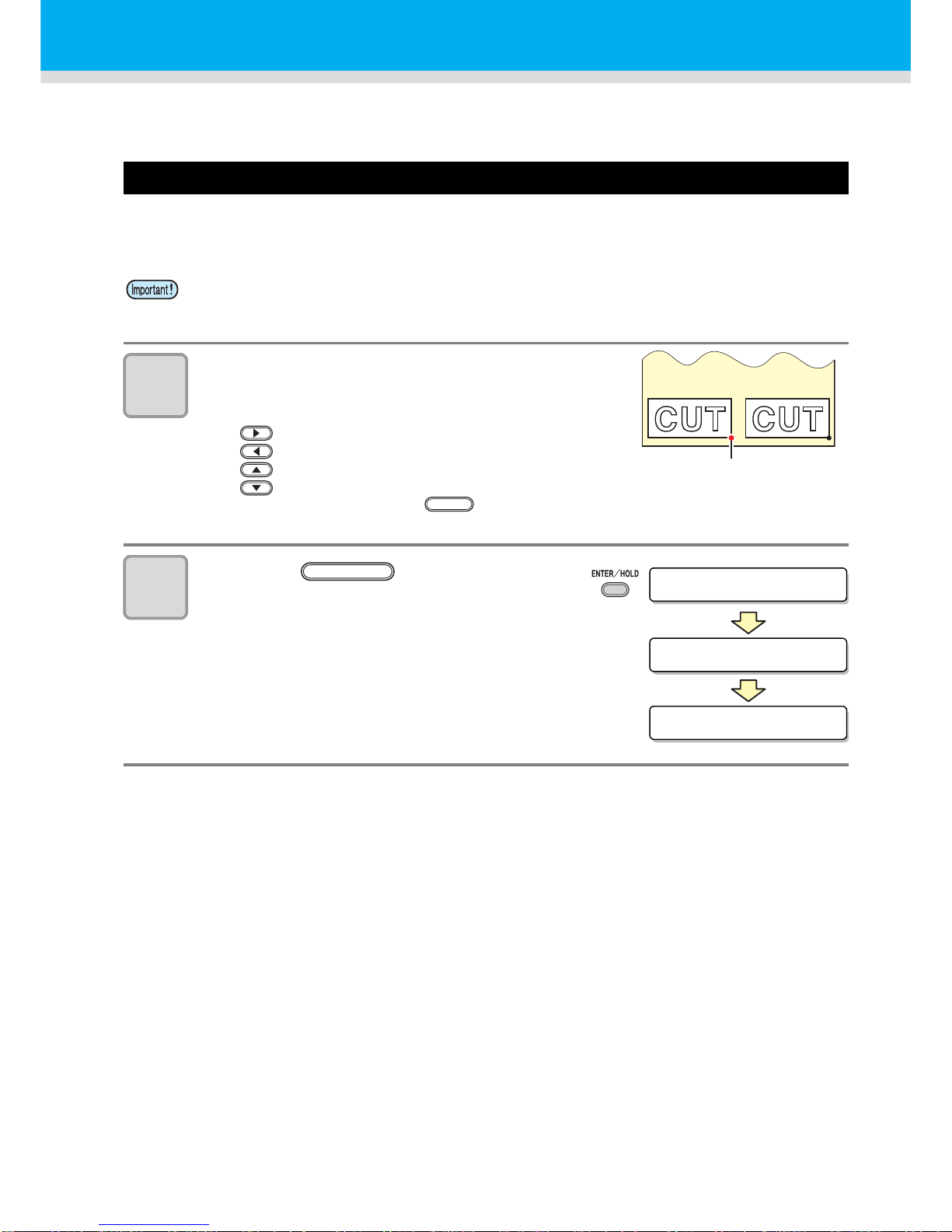
Setting the origin
The origin is a reference point for the cutting (plotting) data.
When the origin is to be changed, set the new origin before starting cutting (plotting).
1
Move the head to a point at which the
new origin is to be set.
• : Moves the head to the right.
: Moves the head to the left.
:Feeds the sheet toward the rear of the plotter.
:Feeds the sheet toward the front of the plotter.
• Every time you press the key, the tool will move up and down alternately.This
helps you to set the origin at a correct position.
2
Press the key to register the
origin.
• The display panel will show the effective cutting
area first and then the tool conditions.
• Change the origin before you make the plotter start cutting for the next data; otherwise, cutting
will be performed over the previous data.
New origin
TOOL
** ORIGIN **
A=**** B=****
CUT1 20 050 0.30
ENTER/HOLD
Page 34
33
Start cutting (plotting)
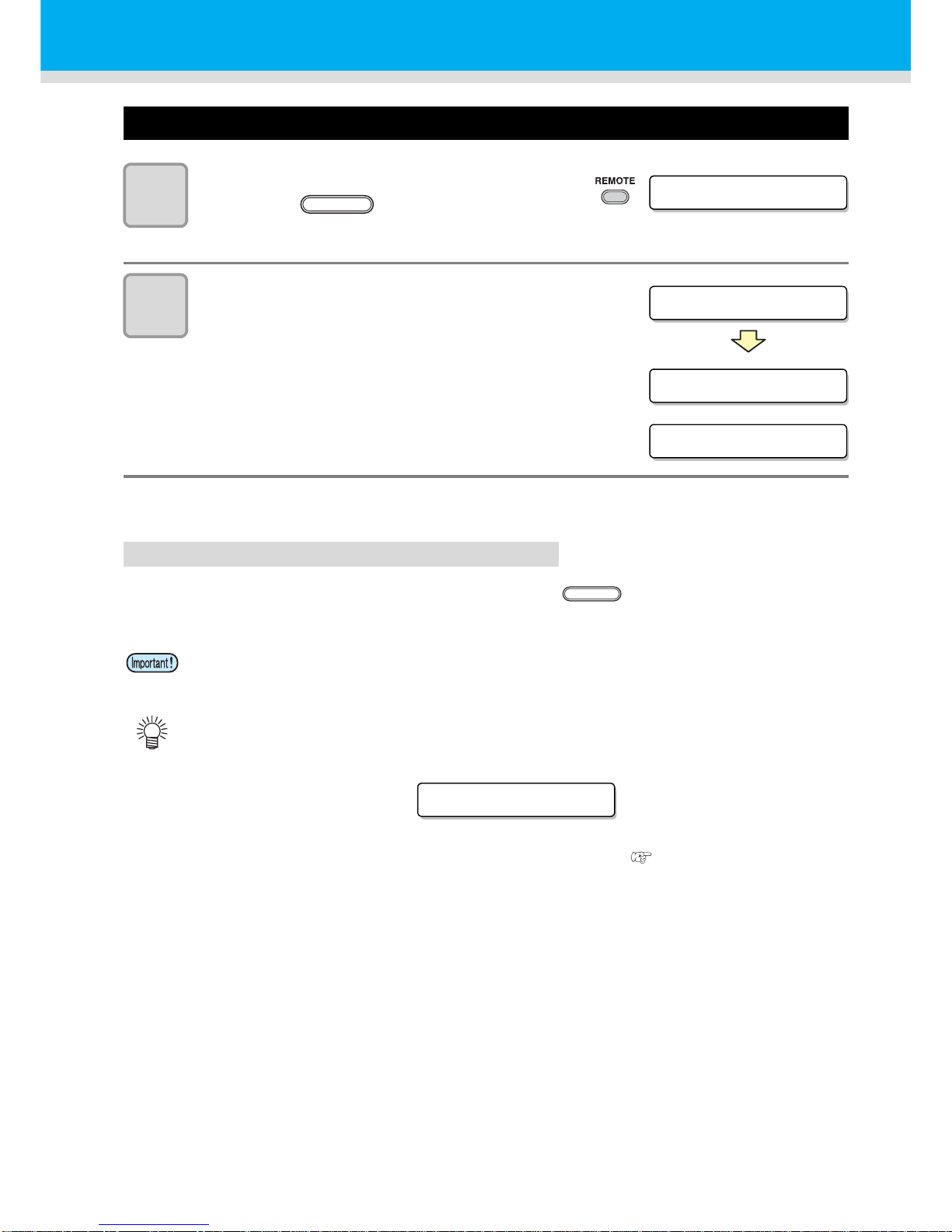
1
After completion of setting the origin,
press the key.
• The display changes to REMOTE.
2
Send the data to the plotter.
• On receiving the data, the plotter performs cutting
(plotting) while displaying the remaining amount of
the data.
• Upon completion of cutting (plotting), the display
changes as shown at right.
Bringing the cutting (plotting) to a halt
To temporarily stop the plotter during cutting (plotting), press the key once. Another press of the
key will make the plotter resume cutt in g (plotting).
• In case the sheet has slipped off the plotter during cutting operation, turn off the power
immediately; otherwise, the main unit may be damaged.
• The LCD will show the following error message if you try to execute any function that can
initiate some action during temporary suspension or any operation that can affect the
command coordinate system.
• If the error message appears, let the plotter complete the cutting for the remaining portion of
the data or discontinue the cutting by executing data clearing ( OPERATION MANUAL).
CUT 1 * REMOTE *
REMOTE
CUT1 * 1356KB *
CUT 1 * REMOTE *
PEN * REMOTE *
When the cutter is selected
When the pen is selected
REMOTE
ERR3 4 DAT REMA I N
Page 35
Cutting (plotting)
34
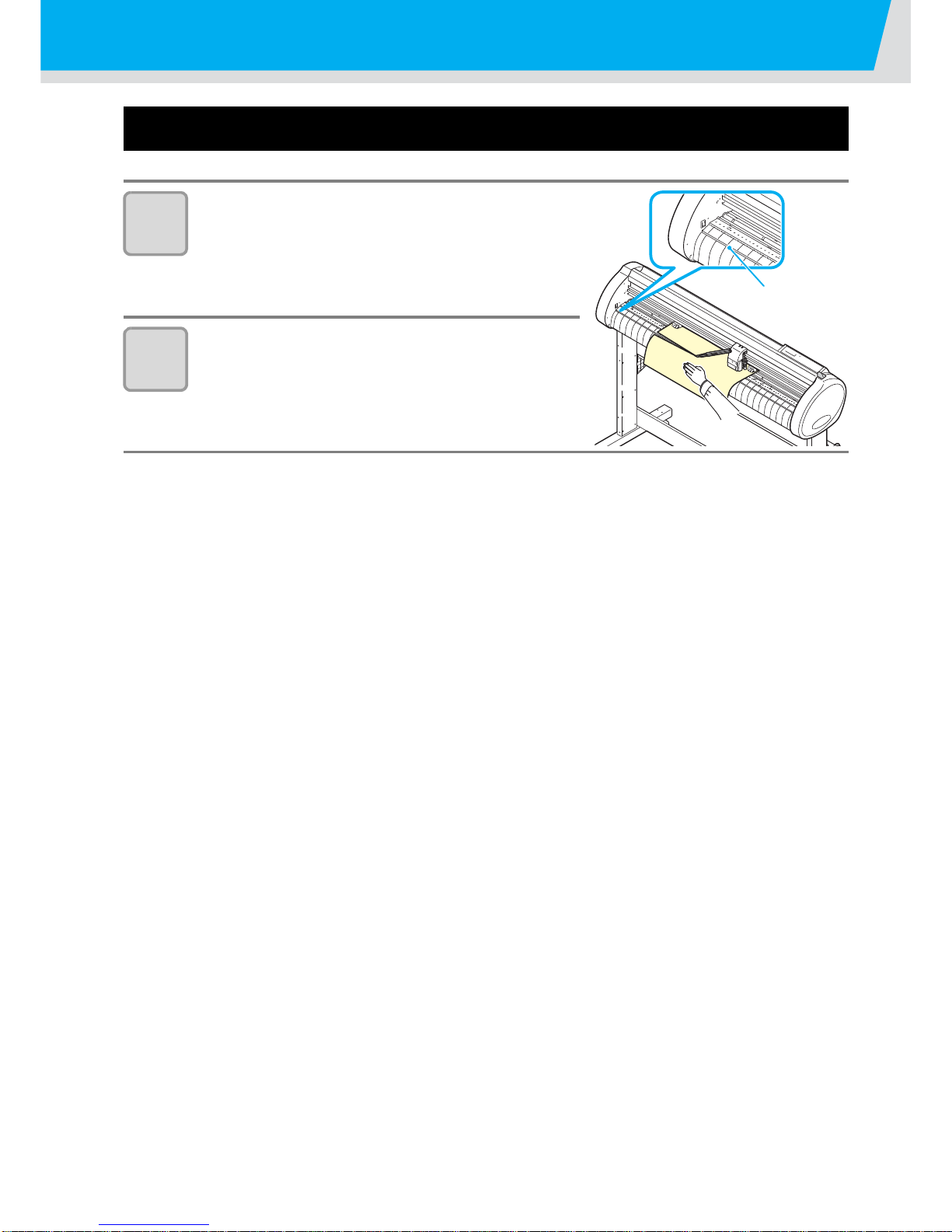
Cut off the Sheet (Manual Cutting)
1
Hold the sheet by hand.
• Make sure to hold firmly to avoid the sheet raiseup.
2
Cut the sheet.
• Cut the sheet with a cutter knife in the slot on the
platen.
Slot
Page 36
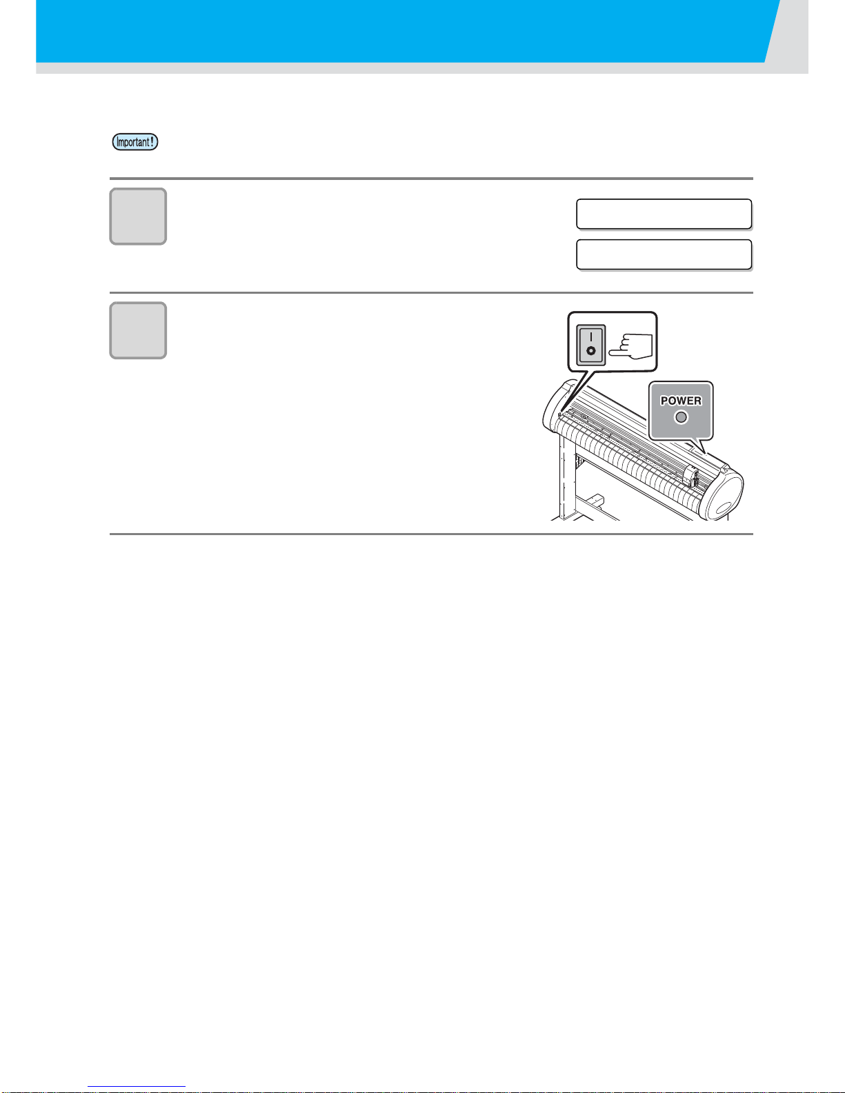
35
Turning the power off
When plotting is completed, press the “ O ” side of the power switch to turn the power off.
1
Confirm that the plotter is not receiving
any data.
• Make sure that the display is indicating REMOTE
or LOCAL.
2
Press the “ O ” side of the power
switch.
• The POWER lamp on the operation panel turns
off.
• Once the power is turned off, wait at least five seconds before turning the power on again.
CUT 1 * REMOTE *
CUT1 20 050 0.30
Page 37
36
Cut Out Data with Registration Mark
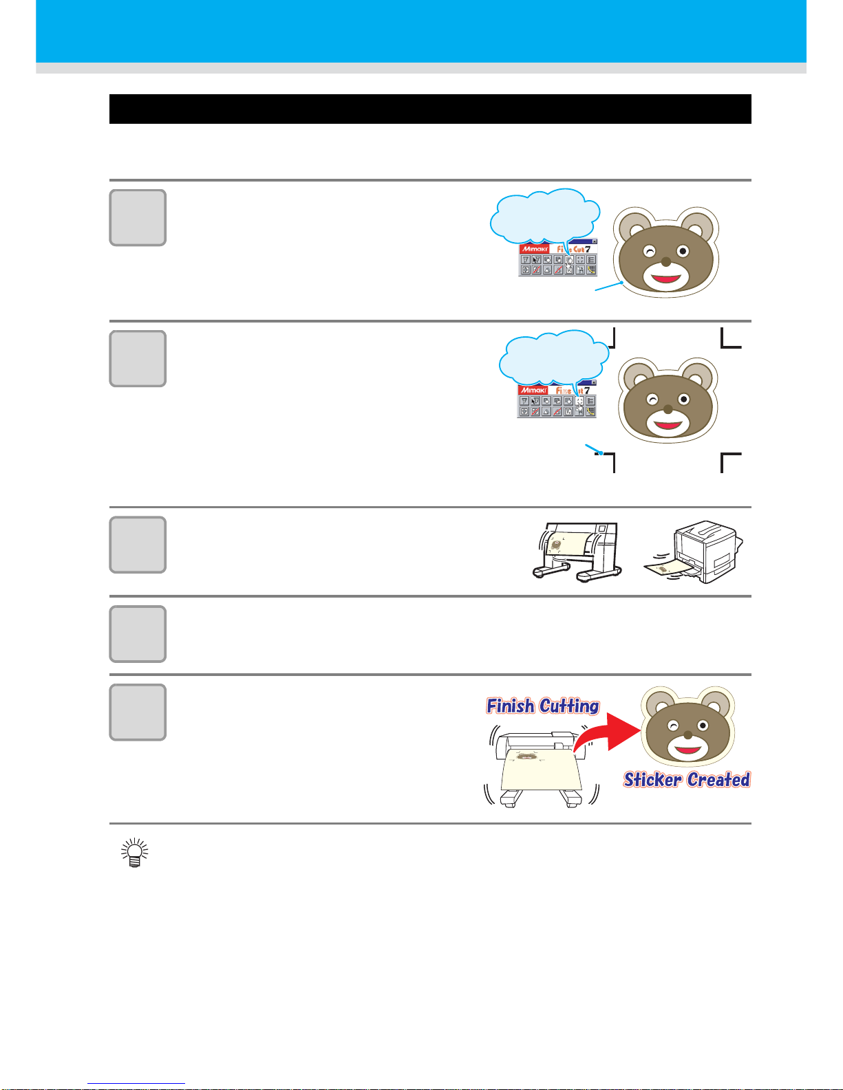
Making sticker with a register mark (When using FineCut)
Create registration marks on an output image that you want to make a seal, and then the plotter detects
them to cut it out.
1
Make frame around the image.
• Make frame with an attached plug-in soft
“FineCut”
2
Make register mark.
• Make register mark at corners of image.
• Cutting start position is settled according to
the register mark.
• Use “FineCut” to make a register mark.
• Refer to P.39 to P.42 for the limitation of
making a register mark.
3
Print the image with register mark.
4
Load the sheet to CG-SRII.
• Refer to P.23 for loading the sheet.
5
Send the data with “FineCut” from
computer, and cut.
• For the operation of plug-in software FineCut, refer to the operation manual provided with a
FineCut CD-ROM.
Frame is attached
around the image.
Click frame
extraction button.
Regismter mark is
created at corners
of image
Click register mark
creation button.
Page 38
37
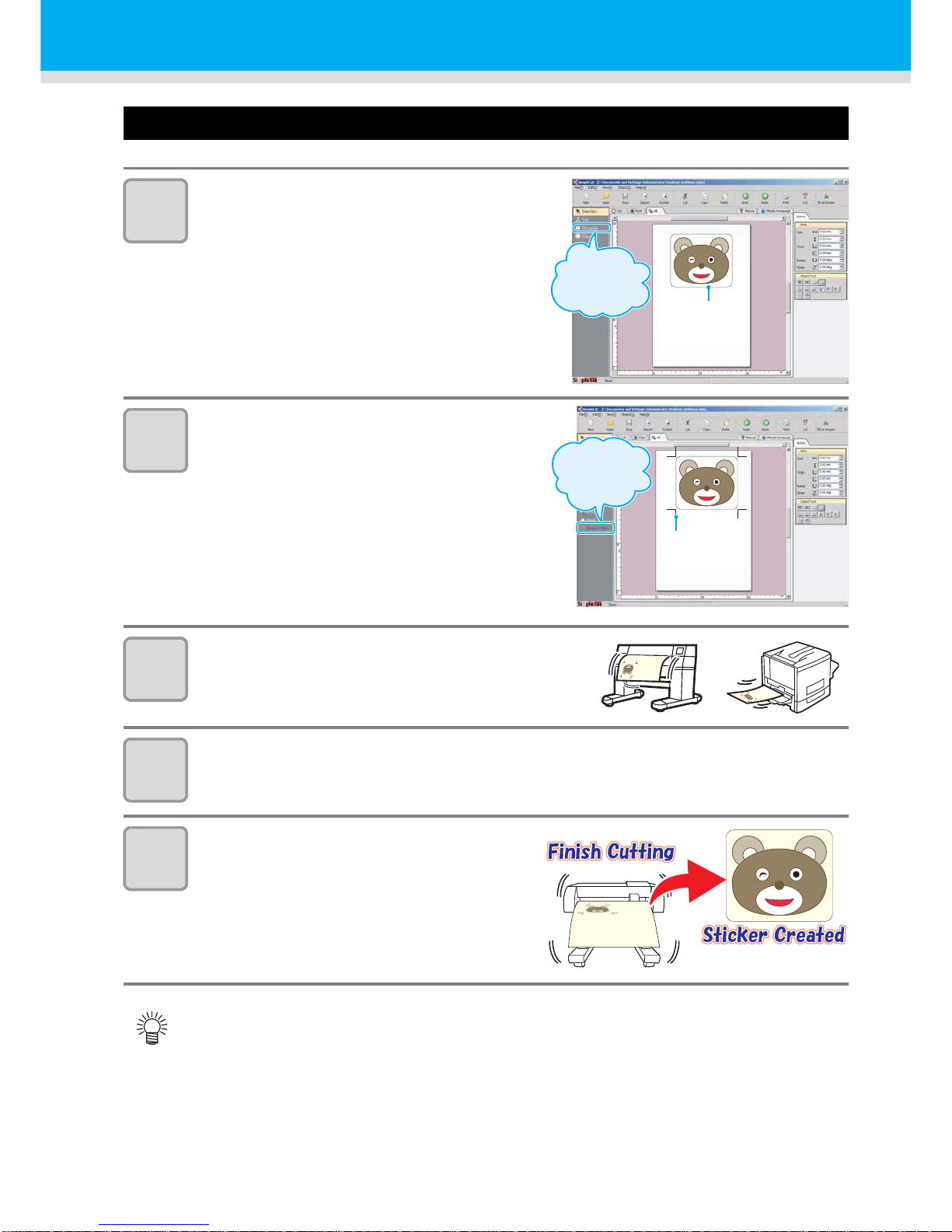
Making sticker with a register mark (When using SimpleCut)
1
Make frame around the image.
• Make frame with an attached plug-in soft
“SimpleCut”
2
Make register mark.
• Make register mark at corners of image.
• Cutting start position is settled according to
the register mark.
• Use “SimpleCut” to make a register mark.
• Refer to P.39 to P.42 for the limitation of
making a register mark.
3
Print the image with register mark.
4
Load the sheet to CG-SRII.
• Refer to P.23 for loading the sheet.
5
Send the data with “SimpleCut”
from computer, and cut.
• For the operation of plug-in software SimpleCut, refer to the operation manual provided with a
SimpleCut CD-ROM.
Use
“Rectangle” to
make a frame.
Fframe
Use “Register
Mark” to make
a register mark.
Register Mark
Page 39
38
Cut Out Data with Registration Mark
Register mark type
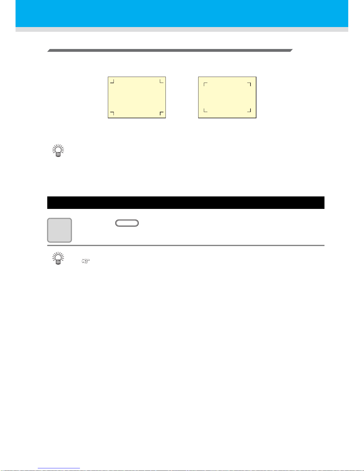
There are following two types of registration marks.
Enter the registration mark detection mode
1
Press the key in the local mode.
• It turns out to be a registration mark detection mode.
• Use the TP4 when performing trapezium compensation to correct the uneven sheet feeding
rate caused by the difference in the diameter between the right and left grit rollers. If the
trapezium compensation is to be omitted, there is no need to set the TP4. In that case,
however, cutting distortion will increase.
• When the registration detection is set to OFF, it doesn’t enter into the reg istration mo de.
(
P.43)
• While various functions are under setting, data entry may be cancelled and the plotter may go
back to the previous setting item.
TP1
TP2
TP3
TP4
TP1
TP2
TP3
TP4
Registration mark: Type 1 Registration mark: Type 2
END
Page 40
39
Precautions in inputting data with registration marks
There are some limitations on preparing data with registration marks.
In order to make full use of this function, read the following instructions carefully and prepare data with
registration marks properly.
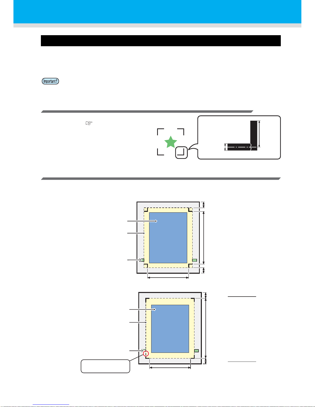
Size of the registration marks
Refer to "The size of, and the distance between,
registration marks"( P.41) for the relationship
between the data and the length of one side of a
registration mark.
The area where registration marks and designs can be arranged
• The TP1 starting position must be 20 mm or more away from the leading edge of the sheet.
• The TP2 end position must be 30 mm or more away from the tail end of the sheet.
Mark Form :
Type 1
Mark Form :
Type 2
• The registration mark described here is intended to detect the sheet inclination a nd the lengths
along the A and B axes. It is not a mark for trimming.
0.3~1.0mm
4~40mm
The area where plotting
(cutting) is permitted
Available cutting area
Pinch roller
30 mm and more
A : Between 50 and 3000 mm
20 mm and more
B : 50 mm and more
The area where plotting
(cutting) is permitted
Available cutting area
Pinch roller
30 mm + or more
Mark length
2
20 mm + or more
Mark length
2
A : Between 50 and 3000 mm
B : 50 mm and more
Keep the marks away
from the pinch rollers.
Page 41
40
Cut Out Data with Registration Mark
No-plotting area around the registration marks
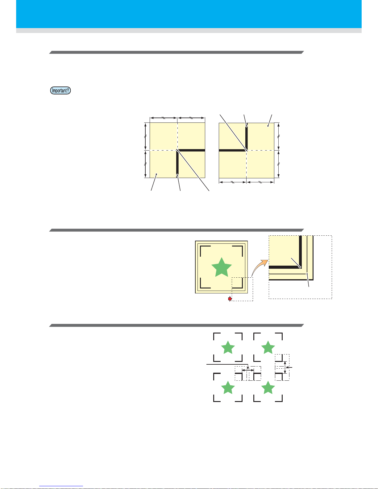
An area around a registration mark (from the mark origin to the mark size area) is a non-plotting area. There
must be no data plotted or stain in this area; otherwise, a wrong origin may be detected or a mark read error
can occur.
Example of cause of wrong detection 1
There is a line outside the registration marks
Example of cause of wrong detection 2
The distance between registration marks
(TP2 and TP1 or TP4 and TP2) is smaller
than the mark length (for Type 2)
• If a wrong mark origin is detected, the cutting will be performed in a wrong area.
Mark size
Mark Form : Type 1
No-plotting area Mark Mark Origin
No-plotting areaMarkMark Origin
Mark Form : Type 2
No-plotting area
Mark Origin
Detected wrong
mark origin
Space larger than
the mark length
Space larger than
the mark length
Page 42
41
The size of, and the distance between, registration marks
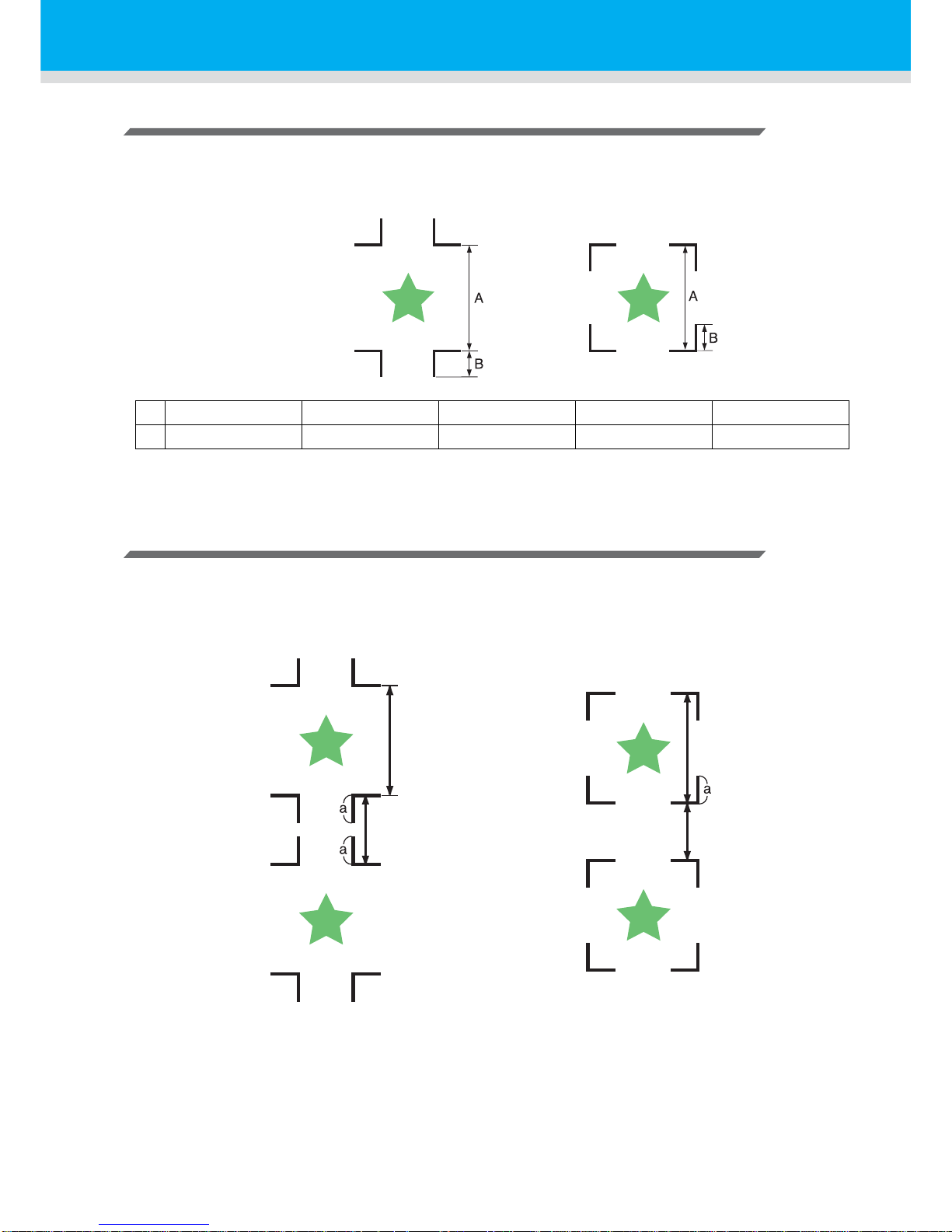
The size (B) of a registration mark suited for the distance (A) between the marks is as shown below.
If the mark size (B) is too small relative to the distance (A), the marks may not be detected correctly.
Be sure to prepare the registration marks with an appropriate size.
(mm)
Distance between registration marks for copied designs
For Type 1 registration marks, the distance between the marks must be not shorter than two times the mark
length and not longer than 1000 mm. For Type 2 registration marks, the distance between the marks must
be not shorter than the mark length and not longer than 1000 mm.
A 200 max. 500 max. 1000 max. 2000 max. 2001 min.
B 4 min. 8 min. 15 min. 25 min. 35 to 40
Mark Form : Type 1 Mark Form : Type 2
Distance between
registration marks =
Between mark length (a) x2
and 1000 mm
50 to 3000 mm
Distance between
registration marks =
Between mark length
(a) and 1000 mm
Page 43
42
Cut Out Data with Registration Mark
Recommended size of the area defined with a set of four registration marks
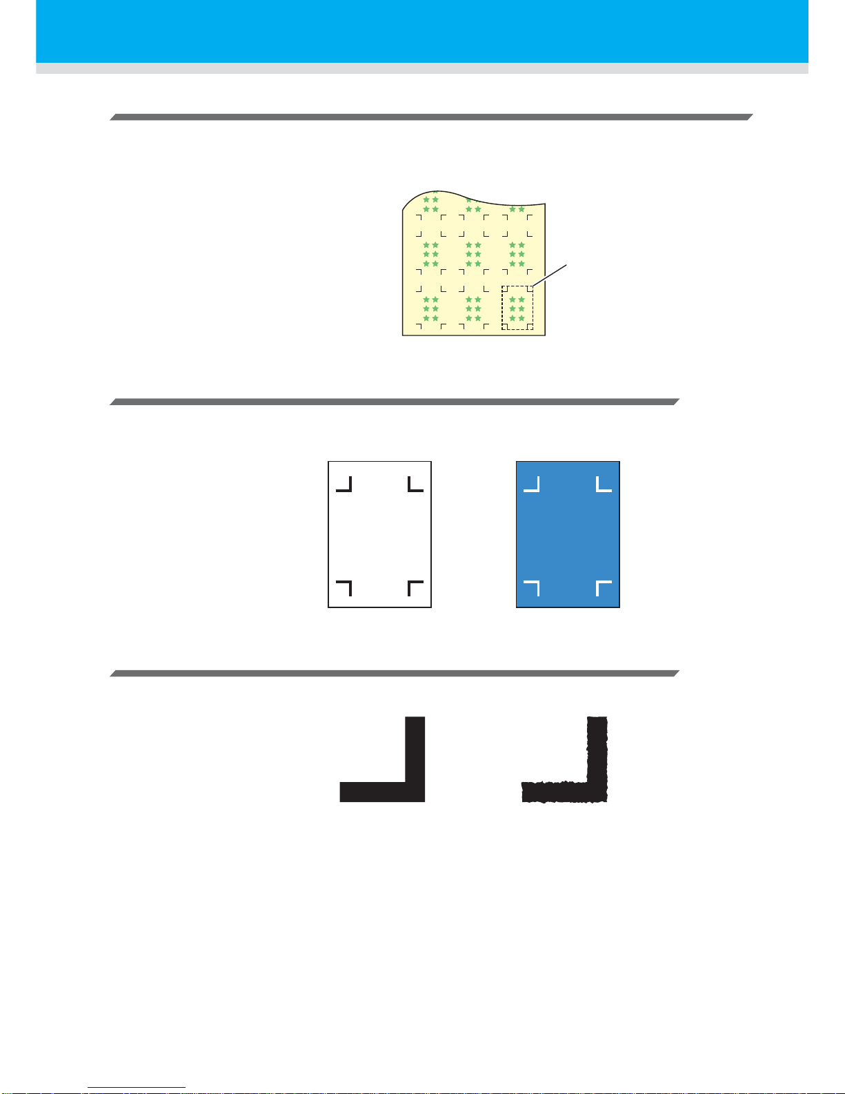
It is recommended that the size of the area defined with a set of four registration marks is in the range of A4
size (210 mm x 297 mm) to A3 size (297 mm x 420 mm). If yo u follow this recommendation, you can
minimize wasteful spaces and arrange the designs efficiently.
Color of mark
The mark must be printed in black against the white background.
The registration mark will not be detected correctly if the background is not white or the mark is not black.
Mark blurred
If the mark is blurred, a wrong mark origin can be detected, thus resulting in deviated cutting.
A4 size (210 mm x 297 mm)
to
A3 size (297 mm x 420 mm)
OK NG
OK
OK
NG
NG
Page 44
43
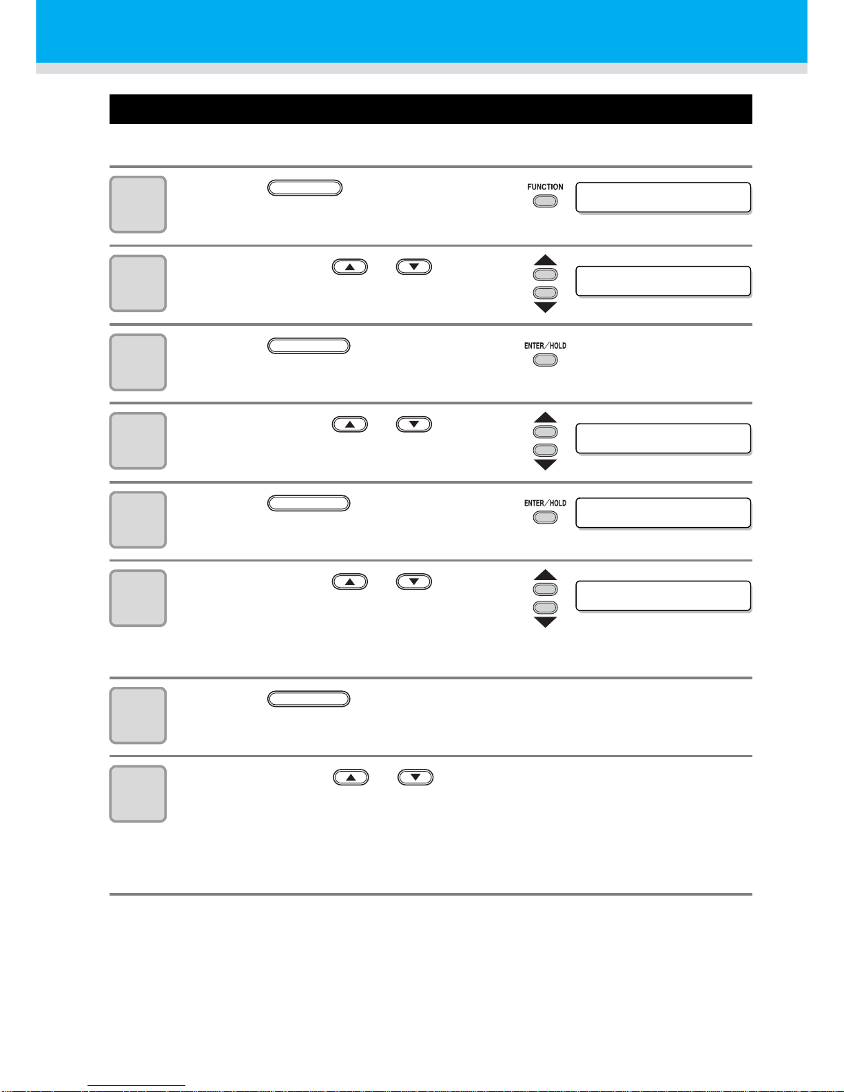
Set for Detecting the Registration Marks
When you want to cut the data with registration marks, you must set the following without fail.
1
Press the key in the local
mode.
2
Press the jog key or to select
[SET UP] .
3
Press the key.
4
Press the jog key or to select
[MARK DETECT] .
5
Press the key.
6
Press the jog key or to select
[Number of detected registration
marks].
• Set values: OFF, 1pt, 2ptA, 2pt B, 3pt, and 4pt
7
Press the key.
• In case you selected “OFF” in Step 6, proceed to Step 12.
8
Press the jog key or to select the following items.
• The following items are provided for the setting of registration mark detection:
Scale compensation, registration mark size, offset A, offset B, form of registration mark,
number of continuous cutting in direction A, number of continuous cutting in direction B,
high speed limit and skew check
• See pages P.44 through P.47 for the contents of each setting item.
DATA CLEAR <ENT>
FUNCTION
SET UP <ENT>
ENTER/HOLD
MARK DETECT< en t >
MARK DETECT :OFF
ENTER/HOLD
MARK DETECT : 2 p t A
ENTER/HOLD
Page 45
44
Cut Out Data with Registration Mark
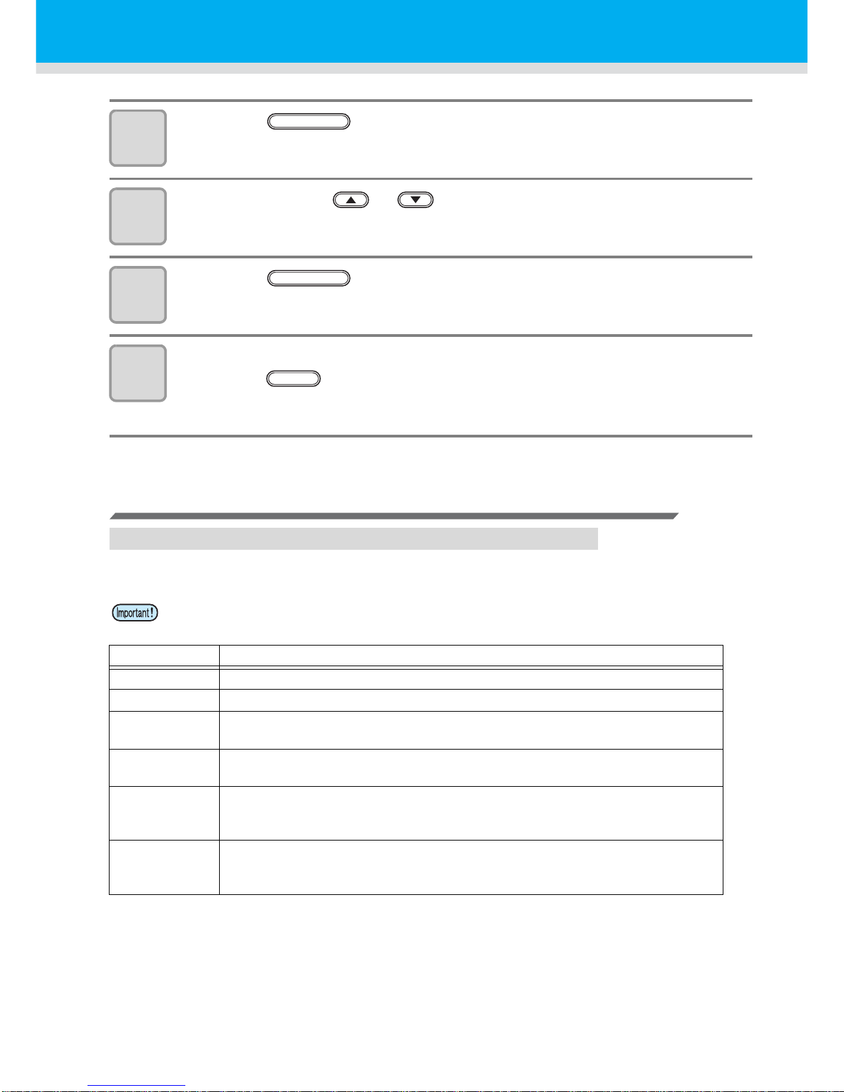
9
Press the key..
10
Press the jog key or to select the set values.
• See pages P.44 through P.47 for the contents of each setting item.
11
Press the key to confirm the value.
12
When you want to terminate this procedure,
press the key twice.
Setting Items
Setting the Number of Registration Mark Detection
The higher the number of detected points, the higher the cutting accuracy.
• Select “1pt” when using FineCut.
Setting Description
OFF
Select this setting for cutting a normal sheet, not for cutting the outline.
1pt
Detects the TP1. Sets only the origin.
2pt A
Detects the two registration marks TP1 and TP2. Performs the skew
compensation and the scale compensation in the sheet feeding direction.
2pt B
Detects the two registration marks TP1 and TP3. Performs the skew correction
and the scale compensation in the width direction.
3pt
Detects the three registration marks TP1, TP2 and TP3. Performs the skew
compensation and the scale compensation in the sheet feeding and the width
direction.
4pt
Detects the four registration marks TP1, TP2, TP3 and TP4. Performs the skew
compensation, the scale compensation in both directions, and the trapezium
compensation.
ENTER/HOLD
ENTER/HOLD
END
Page 46
45
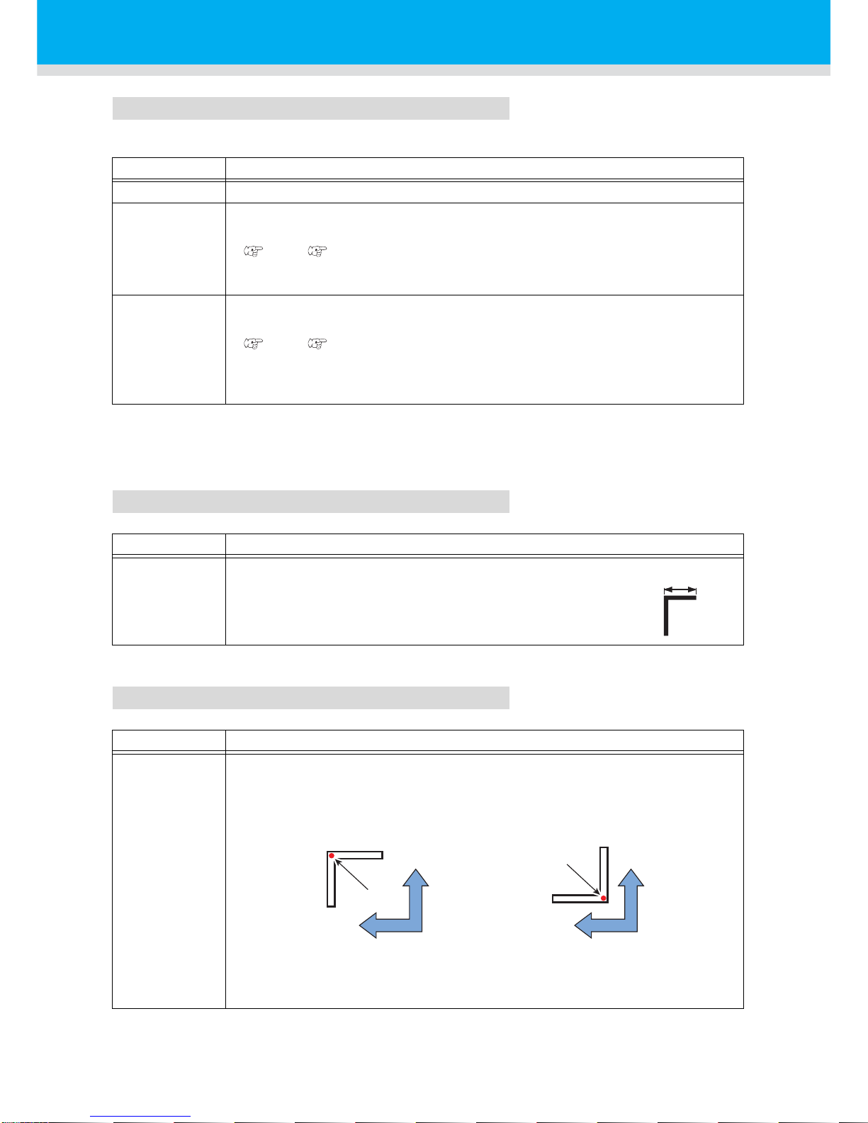
DIST.REVI
Select “OFF” when using FineCut.
Size
Offset A, Offset B
Setting Description
OFF
The plotter will not perform any scale compensation.
BEFOR
With this setting, enter the scale compensation values and the trapezium
compensation
*1
value before executing the registration mark detection.
( P.49 , P.52)
Since the distance between registration marks is entered beforehand, rapid
movement is expected when detecting.
*1:The diameter difference between the grit rollers may cause a significant difference in the sheet feeding
distance between the right side and the left side. The trapezium compensation function correct this
difference in sheet feeding between the right side and the left side.
AFTER
With this setting, enter the scale compensation values and the trapezium
compensation value
*1
after executing the registration mark detection.
( P.49 , P.52)
Since there is an understanding of the distance between marks, setting values
can be input rapidly. The AFTER setting will take less time than the BEFORE
setting.
Setting Description
4 ~ 40mm
Set the length of one side of the registration mark.
When the printed mark's horizontal and vertical lengths dif fer
from each other, set the same value as the shorter length.
Setting Description
± 40.00mm
Generally the origin will be set at the position shown below.
However, the position information of the origin may differ depending on the
application software. In this case, the location of the origin can be corrected.
If the origin is located out of the available cutting area, “ERR37 MARK ORG” will
be displayed. In this case, write the registration marks in the area closer to the
center of the sheet.
Length of one side
Mark: Type 1 Mark: Type 2
Origin
Origin
Plus A
direction
Plus A
direction
Plus B
direction
Plus B
direction
Page 47
46
Cut Out Data with Registration Mark
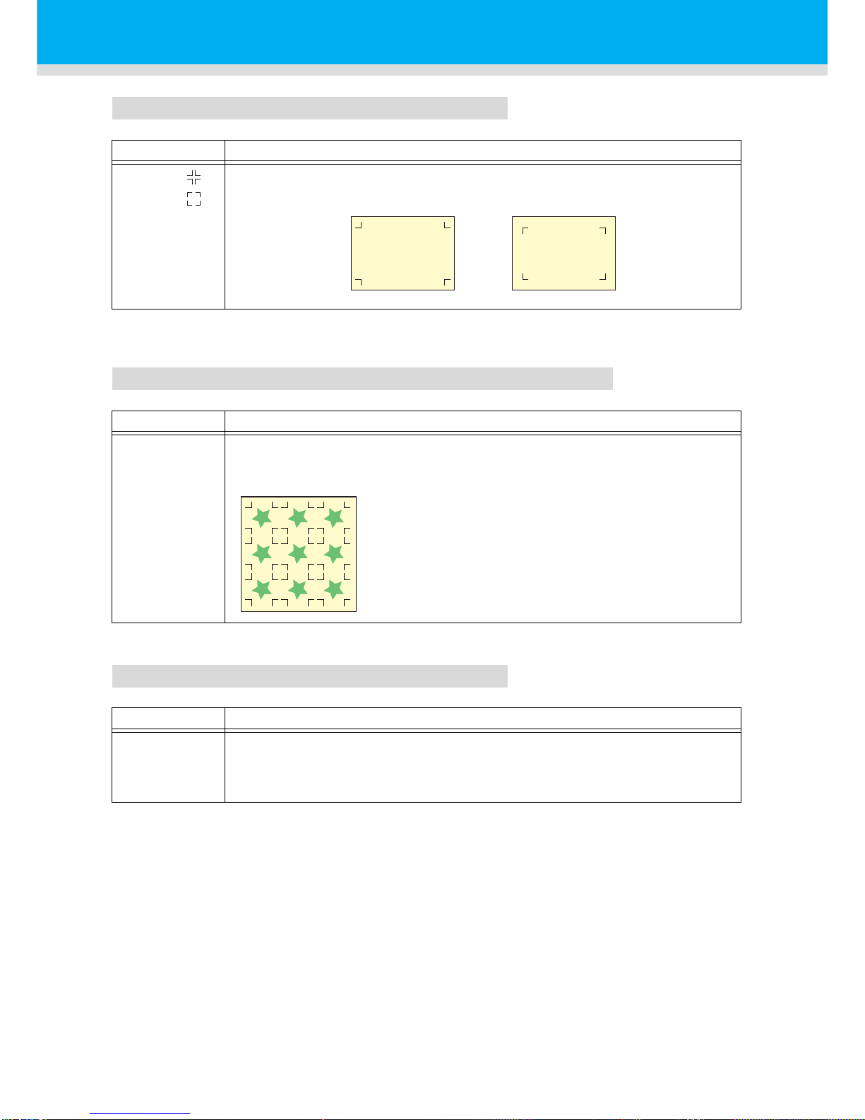
MARK FORM
COPIES A ( UP ), COPIES B ( LEFT )
SPD LIMIT
Setting Description
TYPE1
TYPE2
Select either one of the following type s of registration marks.
Setting Description
1 ~ 9999
(COPIES A)
1 ~ 99
(COPIES B)
Effective when the same pattern is multi-printed at regular intervals.
Cuts automatically the preset number of sheets while detecting registration marks
consecutively based on the first data.
For leaf sheets (cut sheets), the value of [COPIES A] is
used as the number of copies.
When the number of copies can be set on the application
software, like on the supplied FineCut, set the value to [1].
3x3 copies
Setting Description
0 ~ 60cm/s
Set a speed limit for rapid moving in continuous copying.
During rapid moving, mark detection may not be performed correctly if a slippery
sheet is used. In such a case, set a speed limit. If no speed limit is required, set
the value to “0”.
TP1
TP2
TP3
TP4
TP1
TP2
TP3
TP4
Mark: TYPE1 Mark: TYPE2
Page 48
47
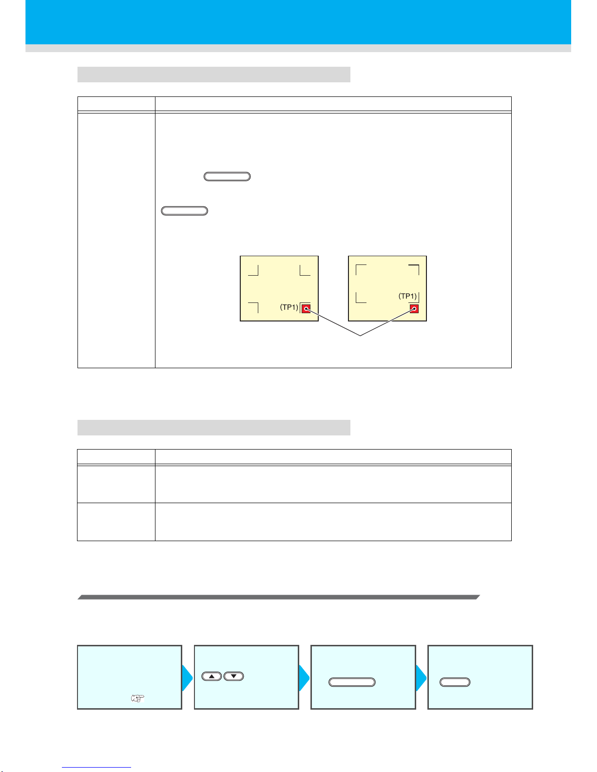
SKEW CHECK
DETECT MODE
Reset the Setting of Registration Mark Detection
In case the plotter detects the sheet that has no printing of registration marks and displays
[SEARCH START POS] you must set the registration mark detection to “OFF.”
Then, the registration mark detection becomes rendered ineffective.
Setting Description
0 ~ 99mm
Set the allowable range of the sheet feeding error when performing continuous
copy .
During continuous copying on a roll sheet, copies may be misaligned little by little
because of sheet skewing. If the error in the B-axis coordinate of the TP1 mark
has exceeded the allowable range, cutting operation is temporally stopped.
Press the key after correcting the sheet feeding error. Then the plotter
waits for mark detection.
Move the light pointer to the position shown below with jog keys and press the
key . Then the light pointer st arts mark detectio n. If skew check is to be
omitted, set the value to “0” .
Setting Description
FAST
The position is determined by scanning the registration mark segment back and
forth once.
Time required for detection is short, however, the accuracy becomes lower a little.
PREC
After scanning the registration mark segment back and forth once, measures the
position without fail by scanning the segment included its outside again.
Time required for detection becomes slightly longer.
Follow the Steps 1
to 5 of "Set for
Detecting the
Registration
Marks"
( P.43)
Press the jog key
to select
“OFF.”
Press the
key.
Press the
key twice.
ENTER/HOLD
ENTER/HOLD
Mark: TYPE1 Mark: TYPE2
Starting point for mark detection
Reference
mark 1
Reference
mark 2
ENTER/HOLD
END
Page 49
48
Cut Out Data with Registration Mark
Method of detecting registration marks
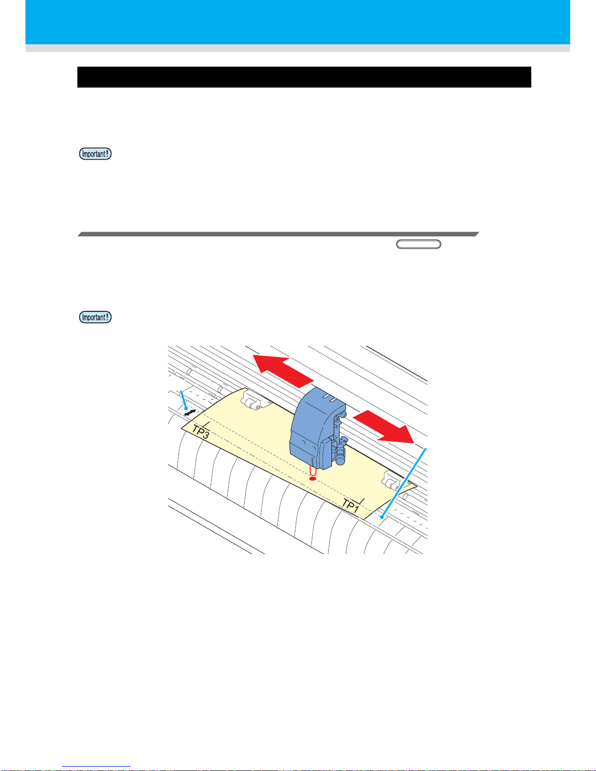
Registration marks are detected in two different ways; full-automatic detection and semi-automatic
detection. Use the semi-automatic function when the TP1 is not located at the bottom right of the sheet, or
when the supplied FineCut is to be used as the cutting software.
Check sheet skew with a light pointer
Depress the clamp lever, raise the pinch roller and reset the sheet with the . And then the Light
Pointer is turned lit. You can manually move the carriage to the left and right.
Depress the clamp lever, and manually move the carriage between the registrations TP1 and TP3. Then
you can confirm the sheet inclination by the move line of Light Pointer. Align to the move line and adjust the
sheet inclination.
• If the sheet is curled, straighten it.
• When using a cutting software having no mark function, use a sheet which has neither stains
nor images in the area (A) located between TP1 and TP2 and in the area (B) located between
TP1 and TP3.
• If no operation is performed for five minutes, the light pointer will automatically go out.
SHEET SET
Moving line of
the light pointer
Sheet skew
Page 50
49
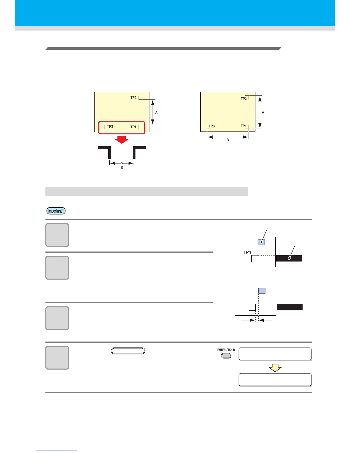
Full-automatic detection of marks
Use this function to correct the error in the detected length between registration marks as compared with
the printed length between registration marks. For this purpose, measure the length A and B on the data
beforehand.
Measure the length between the registration marks.
Detecting procedure ( [DIST.REVI.] Setting value is “BEFOR”)
1
Measure the lengths A and B on the
data to be output.
2
Place TP1 at a location shown at right.
• If it is impossible to place the registration
mark TP1 at the location shown in the
sketch, follow the procedure for “Semiautomatic registration mark detection”.
3
Y ou must t ake care to tighten the sheet,
and raise the clamp lever.
• Then the pinch rollers will retain the sheet.
4
Press the key.
• The scale compensation display appears
after detecting only the sheet width. (The
right figure shows the 4-point detection
display as an example.)
• Be sure to set the sheet in the rear.
Mark: Type 1 Mark: Type 2
5mm
Mark: Type 1
Mark: Type 2
Pinch roller
Cutting line
of plotter
ROL L < R > L EA F
A(1-2)=***.*
ENTER/HOLD
Page 51
50
Cut Out Data with Registration Mark
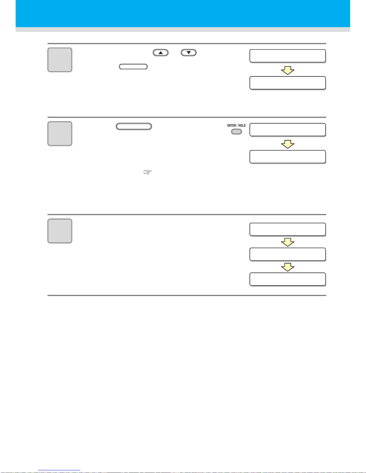
5
Set with the jog key or .
• Press the key. And the plotter
moves to the next scale compensation
setting.
• If [MARK DETECT] is set to [2ptA], the display for
inputting the B length will not appear.
• If [MARK DETECT] is set to [1pt], the scale compensation setting display will not appear
but the origin point will be displayed. (Step 7)
6
Press the key after
completing the settings.
• The registration mark detection will be
started.
• See "Setting the Number of Registration
Mark Detection" ( P.44) for the
number of registration marks.
• In case the plotter cannot detect any
registration marks, it displays “Error 36 in
the registration mark detection” on the
display. Set the sheet again.
7
Set the origin.
• After the detection of the registration marks, the
display will show the available cutting area and
then return to local mode.
A(1-2)=***.*
B(1-3)=***.*
ENTER/HOLD
B(1-3)=***.*
* *MARK DETECT * *
ENTER/HOLD
** ORIGIN **
A=**** B=****
CUT1 20 050 0.30
Page 52
51
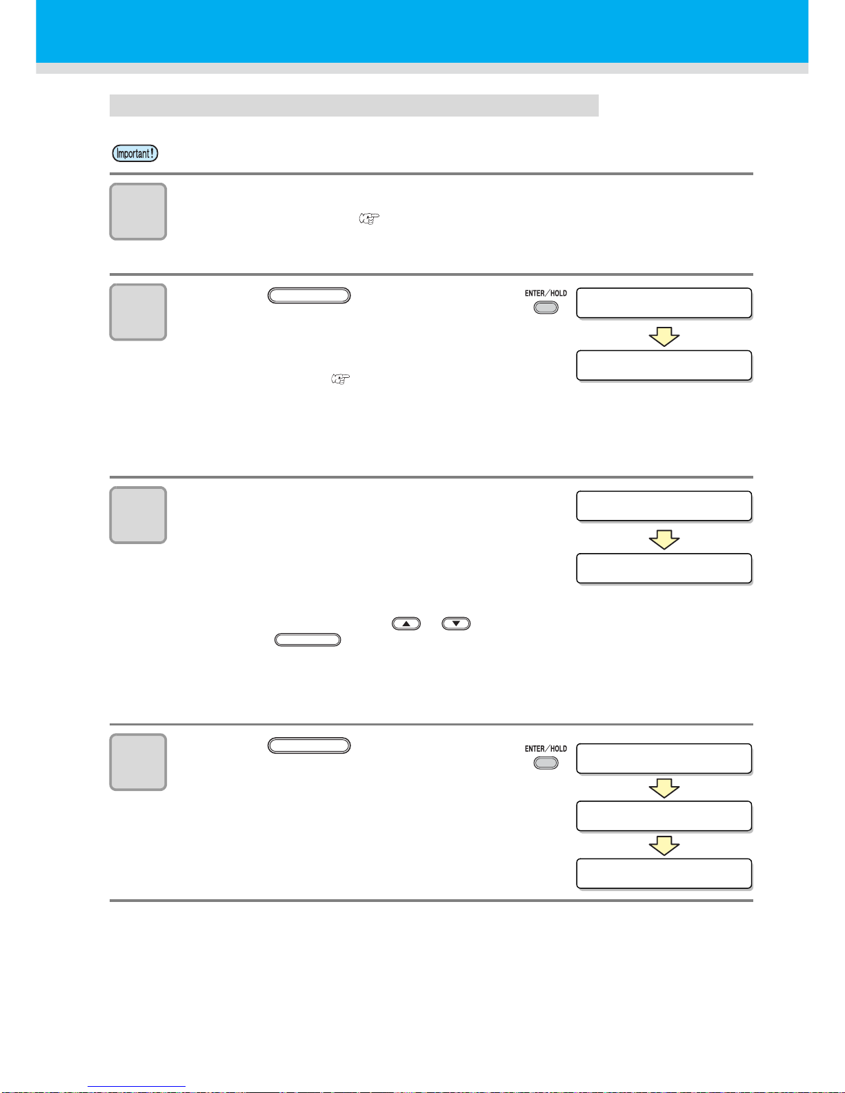
Detecting procedure ( [DIST.REVI.] Setting value is “AFTER”)
1
Follow steps 1 to 3 of "Detecting procedure ( [DIST.REVI.] Setting
value is “BEFOR”)" ( P.49)
2
Press the key.
• The registration mark detection will be
started after detecting only the sheet width.
• See "Setting the Number of Registration
Mark Detection" ( P.44) for the
number of registration marks.
• In case the plotter cannot detect any
registration marks, it displays “Error 36 in
the registration mark detection” on the
display. Set the sheet again.
3
After the detection of the registration
marks, the scale compensation display
appears.
• The right figure shows the 4-point detection
display as an example.
• If there is a difference between the actually measured value and the detected length,
make setting with the jog key or .
• Press the key to change the display to the next scale compensation setting.
• If [DIST. REVI.] is set to [OFF], the display for scale compensation setting will not appear.
• If [MARK DETECT] its set to [2ptA], the display for inputting the B length will not appear.
• If [MARK DETECT] is set to [1pt], the display for scale compensation will not appear.
Proceed to Step 4 and set the origin.
4
Press the key after
completing the settings.
• Set the origin.
• The display will show the available cutting
area and then return to local mode.
• Be sure to set the sheet in the rear.
ROL L < R > L EA F
* *MARK DETECT * *
ENTER/HOLD
A(1-2)=***.*
B(1-3)=***.*
ENTER/HOLD
** ORIGIN **
A=**** B=****
CUT1 20 050 0.30
ENTER/HOLD
Page 53
52
Cut Out Data with Registration Mark
Semi-automatic detection of registration marks
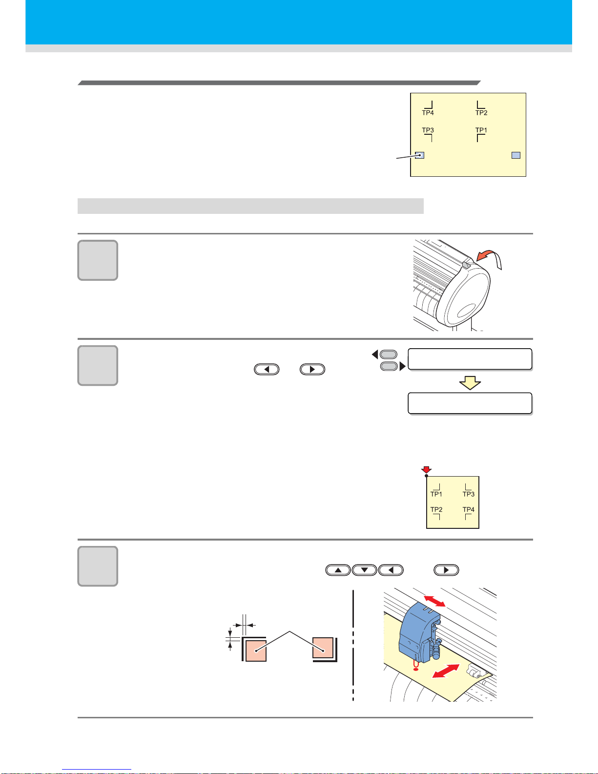
When TP1 cannot be located at the position where it can be
detected full-automatically or when no registration mark can
be detected full-automatically, perform registration mark
detection semiautomatically.
Detecting procedure ( [DIST.REVI.] Setting value is “BEFOR”)
1
Load the sheet and lower the clamp lever.
• Then the pinch rollers will retain the sheet.
2
Perform the sheet detection by
pressing the jog key or .
(Set the sheet in the rear.)
• Once the sheet is detected, the display
indicates that the plotter is waiting for
registration mark detection operation.
• When the sheet is set in the front, the
positions of the TP1 to TP4 are viewed
inverted as shown at right.
3
Move the Light Pointer into the area shown below by pressing the
appropriate ones of the jog keys and .
Pinch roller
ROL L < R > L EA F
SEARCH START POS
Origin
1 mm or
more away
Mark detection
position
Mark :
Type 1
Mark :
Type 2
Page 54
53
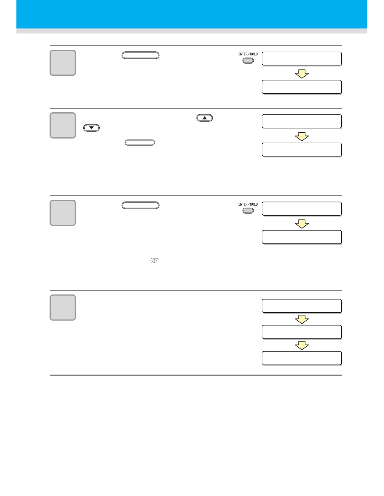
4
Press the key.
• The scale compensation display appears.
(The right figure shows the 4-point detection display
as an example.)
5
Make setting with the jog key or
.
• Press the key to change the
display to the next scale compensation
setting.
• If [DIST.REVI.] is set to [OFF], the display for scale compensation setting will not appear.
• If [MARK DETECT] its set to [2ptA], the display for inputting the B length will not appear.
• If [MARK DETECT] is set to [1pt], the scale compensation setting display will not appear
but the origin point will be displayed.
6
Press the key after
completing the settings.
• The plotter will start detecting the
registration marks according to the settings
of [MARK DETECT].
• See "Setting the Number of Registration
Mark Detection" ( P.44) for the
number of registration marks.
• In case the plotter cannot detect any registration marks, it displays “Error 36 in the
registration mark detection” on the display. Set the sheet again.
7
Set the origin.
• The display will show the available cutting
area and then return to local mode.
SEARCH START POS
A(1-2)=***.*
ENTER/HOLD
A(1-2)=***.*
B(1-3)=***.*
ENTER/HOLD
B(1-3)=***.*
* *MARK DETECT * *
ENTER/HOLD
** ORIGIN **
A=**** B=****
CUT1 20 050 0.30
Page 55
54
Cut Out Data with Registration Mark
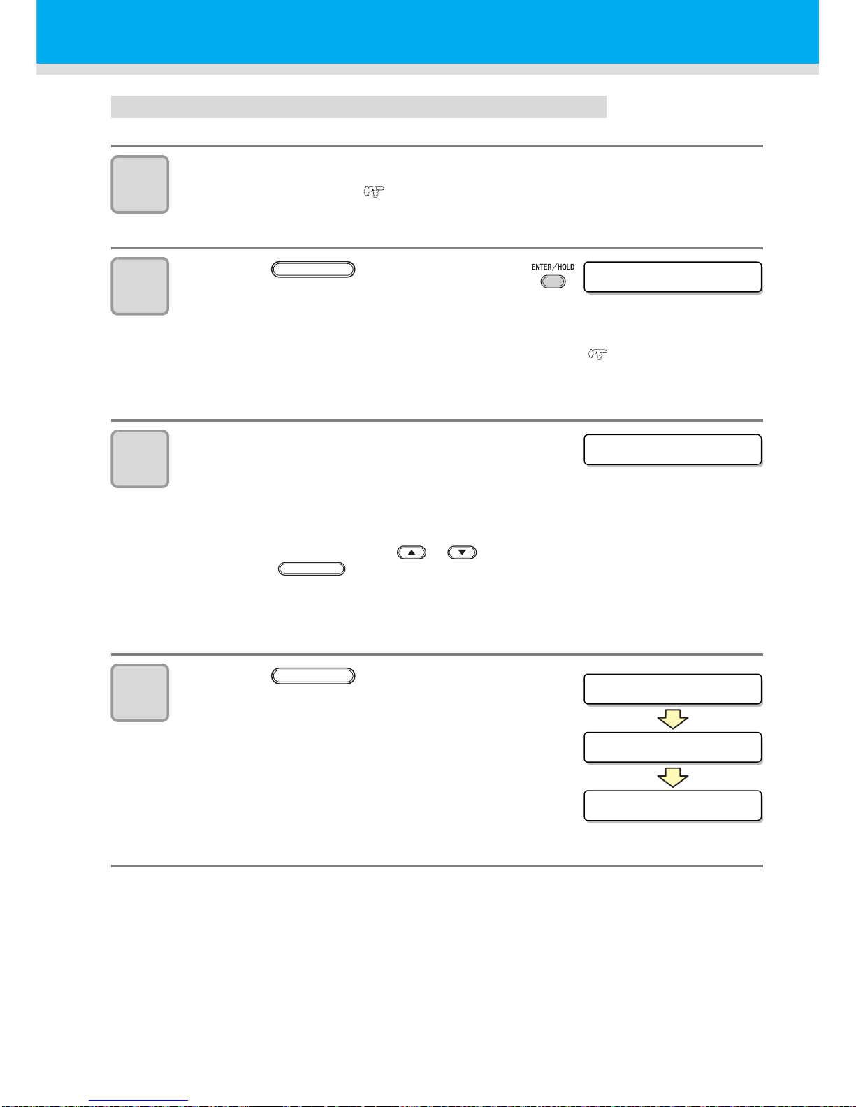
Detecting procedure ( [DIST.REVI.] Setting value is “BEFOR”)
1
Follow steps 1 to 3 of "Detecting procedure ( [DIST.REVI.] Setting
value is “BEFOR”)" ( P.52)
2
Press the key.
• The plotter will start detecting the
registration marks according to the settings
of [MARK DETECT].
• See "Setting the Number of Registration Mark Detection" ( P.44) for the number of
registration marks.
• In case the plotter cannot detect any registration marks, it displays “Error 36 in the
registration mark detection” on the display. Set the sheet again.
3
After the detection of the registration
marks, the scale compensation display
appears.
• The right figure shows the 4-point detection display as an example.
• If there is a difference between the actually measured value and the detected length,
make setting with the jog key or .
• Press the key to change the display to the next scale compensation setting.
• If [DIST.REVI.] is set to [OFF], the display for scale compensation setting will not appear.
• If [MARK DETECT] is set to [2ptA], the display for inputting the B length will not appear.
• If [MARK DETECT] is set to [1pt], the scale compensation setting display will not appear
but the origin point will be displayed.
4
Press the key after
completing the settings.
• Set the origin.
• The display will show the available cutting area
and then return to local mode.
* *MARK DETECT * *
ENTER/HOLD
A(1-2)=***.*
ENTER/HOLD
** ORIGIN **
A=**** B=****
CUT1 20 050 0.30
ENTER/HOLD
Page 56
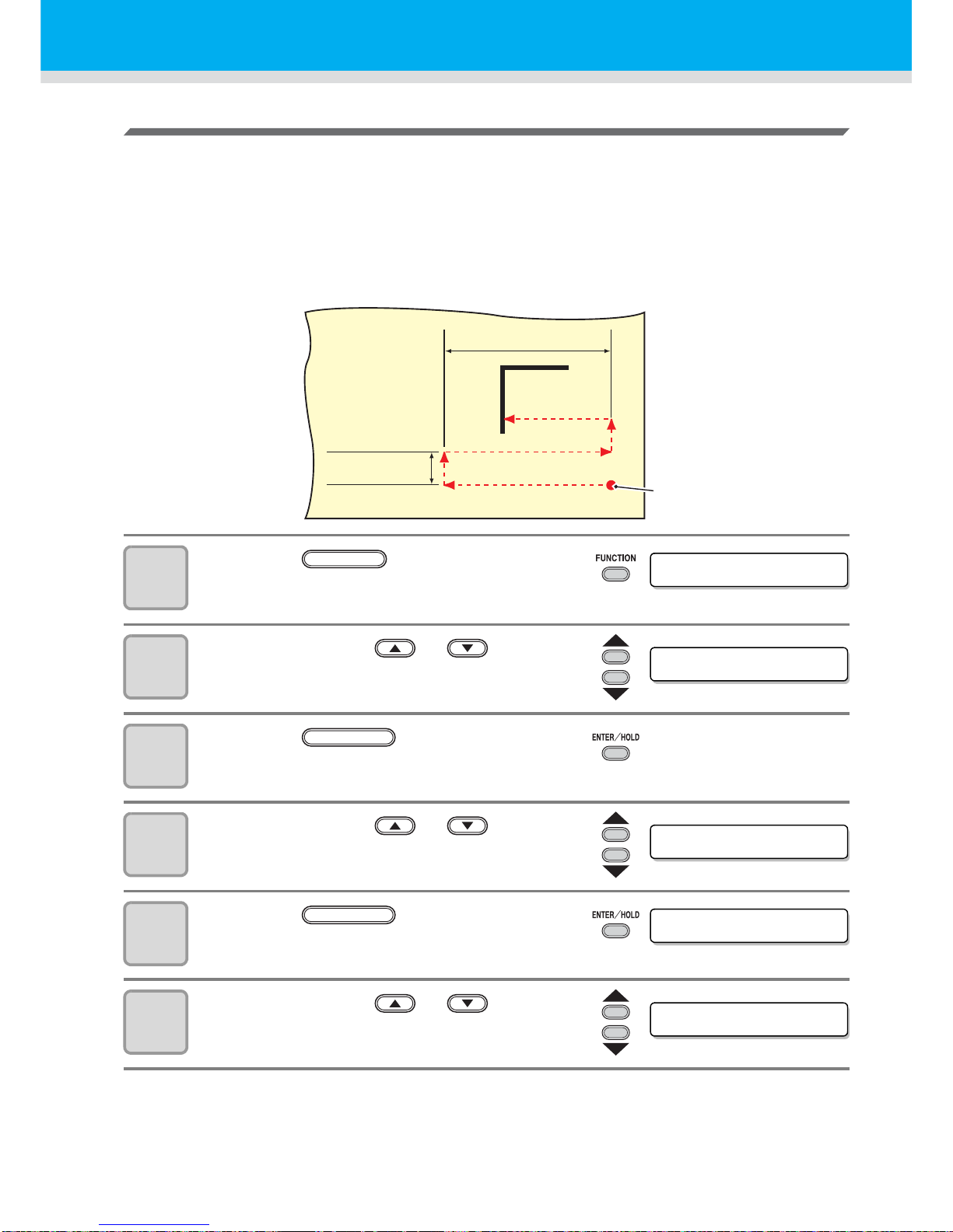
55
Detect a registration mark automatically after the sheet is detected
Set the automatic registration mark search function performed after the sheet is detected.
If both of the registration mark detection and the registration mark search is valid , the fu nction will search
the registration mark automatically after the sheet is detected.
From the original point after detecting the sheet, it scans the set scan width back and forth at half intervals
of the registration mark size. Then, when it finds a segment, a point or a printed material, the registration
mark detection will be performed.
If the vertical line and the horizontal line are detected properly, it is recognized as a registration mark and
the original point setting will be performed.
1
Press the key in the local
mode.
2
Press the jog key or to select
[SET UP] .
3
Press the key.
4
Press the jog key or to select
[SEARCH MARK] .
5
Press the key.
6
Press the jog key or to select
“ON”.
Scan width
Half of registration
mark size
Original point after
detecting the sheet
DATA CLEAR <ENT>
FUNCTION
SET UP <ENT>
ENTER/HOLD
SEARCH MARK<en t >
SEARCH MARK:OFF
ENTER/HOLD
SEARCH MARK:ON
Page 57
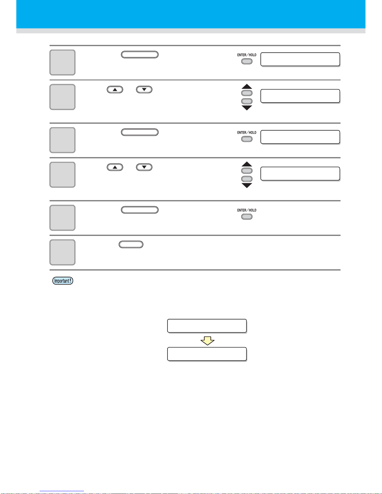
56
Cut Out Data with Registration Mark
7
Press the key.
8
Press or key to select the
scan width.
• Set values: 10 to 30cm
9
Press the key.
10
Press or key to select the
search range.
• Set values: 10 to 50cm
11
Press the key.
12
Press the
key twice for terminating this function.
• If it is not recognized as a registration mark or there is no response even if the function scans
the area set for search, the message indicating the search failure will be displayed in a
certain time.
Then, it will return to the original point and the mode will move to the normal semi-automatic
registration mark detection mode.
SCAN WI DTH:10cm
ENTER/HOLD
SCAN WI DTH:20cm
SearchRange:10cm
ENTER/HOLD
SearchRange:30cm
ENTER/HOLD
END
SEARCH FA I LED
SEARCH START POS
Page 58
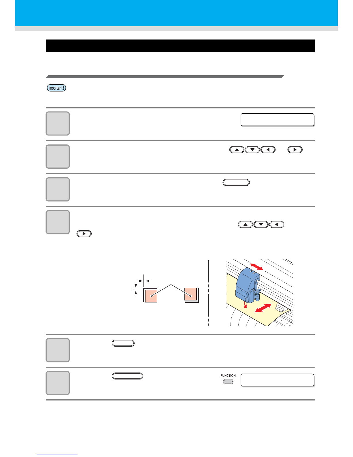
57
Confirm the following when failed in cutting correctly.
Check the sensor for the registration mark detection
1
Make sure that the plotter is in local
mode.
2
Enter the jog mode by pressing the jog key or
3
Turn on the Light Pointer by pressing the key.
4
Move the Light Pointer to the registration mark detection position by
pressing the appropriate ones of the jog keys and
.
• Perform registration mark detection at a position 1mm or more away from the registration
mark.
5
Press the key to terminate the jog mode.
• The plotter returns to the local mode.
6
Press the key.
• If you move the head and sheet manually , you cannot perform the right response check.
Be sure to perform it via the following operations.
CUT1 20 050 0.30
REMOTE
1 mm or
more away
Mark detection
position
Mark :
Type 1
Mark :
Type 2
END
DATA CLEAR <ENT>
FUNCTION
Page 59
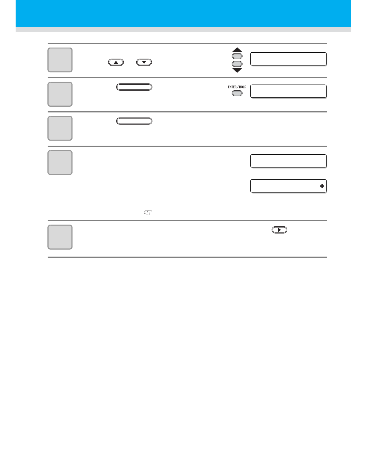
58
Cut Out Data with Registration Mark
7
Select [MARK sensor] by pressing the
jog key or .
8
Press the key.
9
Press the key after confirming [SENSOR CHK] is
displayed.
10
Select the length of the registration
mark, shape of the registration mark,
and speed of the registration mark
detection.
• For details on setting the [SIZE] and
[FORM], refer to the [MARK DETECT]
setting procedure. (
P.39)
11
Perform registration mark detection with the jog key .
( Next page)
MAR K s e n s o r < ENT>
SENSOR CHK <en t >
ENTER/HOLD
ENTER/HOLD
SIZE :10mm
FORM :TYPE1
Page 60
59
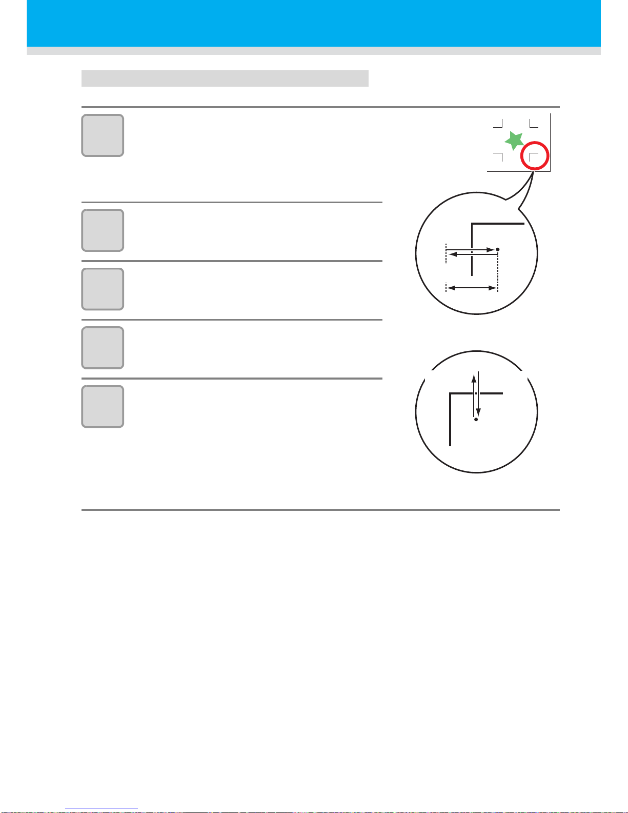
Detect operation
1
Scan in the B direction (plus direction)
to detect the line.
• The buzzer sounds when the line is
detected. If the line is not detected, the
buzzer does not sound.
2
Scan in the B direction (minus
direction) to detect the line.
3
Scan in the A direction (plus direction)
to detect the line.
4
Scan in the A direction (minus
direction) to detect the line.
5
Follow the Steps 1 to 4, and confirm if
the buzzer sounds 4 times.
• When the detection behavior completes
successfully, the buzzer sounds 4 times.
• If the plotter cannot detect the line successfully
even after you adjusted the sensitivity, you must
verify the registration conditions and contact our
sales branches (for service call).
Minus
direction
Plus
direction
Mark length
Scan in the A direction
Scan in the B direction
Minus
direction
Plus
direction
Page 61
60
Cut Out Data with Registration Mark
Correct the light pointer position
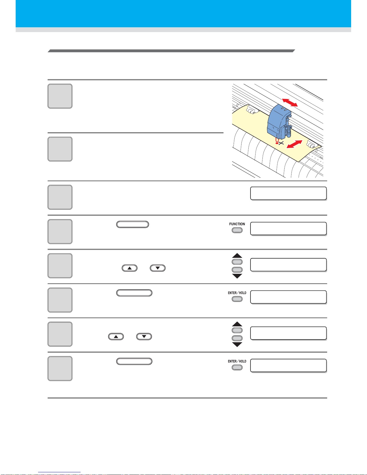
If the plotter fails to recognize any registration mark properly, the possible cause is an error in the positional
relationship between the MARK sensor and the light pointer.
In this case, adjust the position of the lig ht pointer.
1
Install a cutter in the tool holder.
2
Load the copy paper.
3
Confirm that the plotter is in the local
mode.
4
Press the key.
5
Select [MARK SENSOR] by pressing
the jog key or .
6
Press the key.
7
Select [POINTER OFS] by pressing the
jog key or .
8
Press the key.
• A 10 mm by 10 mm cross pattern will be
cutted.
• The light pointer turns on and moves to the center of the cross pattern.
CUT1 20 050 0.30
DATA CLEAR <ENT>
FUNCTION
MAR K s e n s o r < ENT>
SENSOR CHK <en t >
ENTER/HOLD
POINTER OFS<en t>
A=-3 . 9 B=-6. 0
ENTER/HOLD
Page 62

61
9
By pressing the jog keys and , adjust the light
pointer position so that the center of the light pointer is in alignment
with the center of the cross pattern.
10
Press the key.
• The plotter will return to the local mode after
registering the compensation value.
CUT1 20 050 0.30
ENTER/HOLD
Page 63
62
Cut Out Data with Registration Mark
Alignment of MARK SENSOR
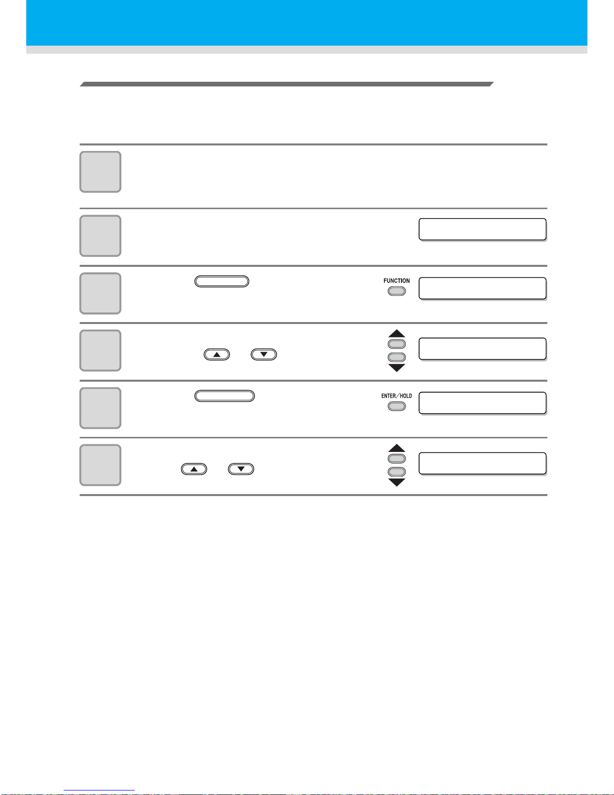
The offset value of the cutter and the mark sensor can be adjusted.
Set the sheet on which the register mark is printed.
Usable on Firmware Ver.1.1 or lator.
1
Install a cutter in the tool holder.
2
Confirm that the plotter is in the local
mode.
3
Press the key.
4
Select [MARK SENSOR] by pressing
the jog key or .
5
Press the key.
6
Select [SENSOR OFS] by pressing the
jog key or .
CUT1 20 050 0.30
DATA CLEAR <ENT>
FUNCTION
MAR K s e n s o r < ENT>
SENSOR CHK <en t >
ENTER/HOLD
SENSOR OFS <en t >
Page 64
Cut Out Data with Registration Mark
63
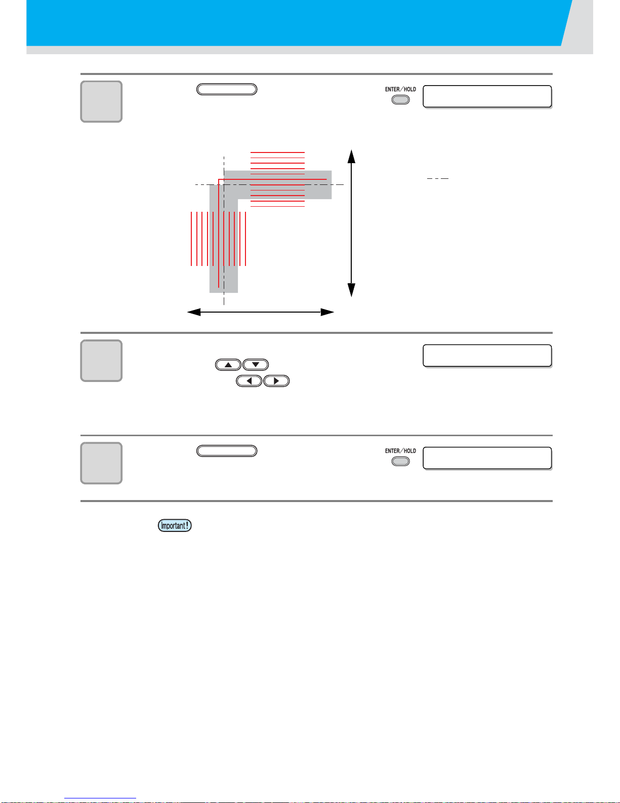
7
Press the key.
• The offset value of the cutter and the mark sensor
can be adjusted.
• Set the sheet on which the register mark is printed.
8
Enter the corrected value (mm) by
pressing the for the A
direction, or the for the B
direction.
• If misaligned by +0.2 mm, enter "-0.2".
9
Press the key.
• The plotter will return to the local mode after
registering the compensation value.
• The setting values are kept in memory even when the power is turned off.
• The sensor offset value selected by this operation is not initialized by SETUP
RESET operation.
A=0 .0 B=0. 0
ENTER/HOLD
A direction
B direction
Misaligned by +0.2 mm from
the center line of the register
mark ( ) in the A and the
B direction.
A=-0 . 2 B=-0. 2
CUT1 20 050 0.30
ENTER/HOLD
Page 65

Page 66

Page 67

D202007-14-30112011
Page 68

NH
FW : 1.2
© MIMAKI ENGINEERING CO., LTD.2011
 Loading...