

Page 1

Cat. No.
No de Cat.
Cat. No.
5337-20, 5337-21
5339-20, 5339-21
5340-20, 5340-21
5342-20, 5342-21
OPERATOR'S MANUAL
MANUEL de L'UTILISATEUR
MANUAL del OPERADOR
HEAVY-DUTY ROTARY HAMMERS AND DEMOLITION HAMMERS
EXTRA ROBUSTES MARTEAUX ROTATIFS ET MARTEAU DE DÉMOLISSEUR
ROTOMARTILLOS Y MARTILLOS PERFORADORES DE
DEMOLICIÓN HEAVY-DUTY
TO REDUCE THE RISK OF INJURY, USER MUST READ OPERATOR'S MANUAL.
AFIN DE RÉDUIRE LE RISQUE DE BLESSURES, L'UTILISATEUR DOIT LIRE LE MANUEL DE L'UTILISATEUR.
PARA REDUCIR EL RIESGO DE LESIONES, EL USUARIO DEBE LEER EL MANUAL DEL OPERADOR.
Page 2

page 2
Page 3
GENERAL SAFETY RULES — FOR ALL POWER TOOLS
WARNING
Failure to follow all instructions listed below may result in electric shock, fi re and/or serious injury. The term "power tool" in all of the
warnings listed below refers to your mains-operated (corded) power tool or battery-opearted (cordless) power tool.
SAVE THESE INSTRUCTIONS
READ ALL INSTRUCTIONS
WORK AREA SAFETY
1. Keep work area clean and well lit. Cluttered or dark areas invite accidents.
2. Do not operate power tools in explosive atmospheres, such as
in the presence of fl ammable liquids, gases, or dust. Power tools
create sparks which may ignite the dust or fumes.
3. Keep children and bystanders away while operating a power tool.
Distractions can cause you to lose control.
ELECTRICAL SAFETY
4. Power tool plugs must match the outlet. Never modify the plug in
any way. Do not use any adapter plugs with earthed (grounded)
power tools. Unmodifi ed plugs and matching outlets will reduce risk
of electric shock.
5. Avoid body contact with earthed or grounded surfaces such as
pipes, radiators, ranges and refrigerators. There is an increased risk
of electric shock if your body is earthed or grounded.
6. Do not expose power tools to rain or wet conditions. Water entering
a power tool will increase the risk of electric shock.
7. Do not abuse the cord. Never use the cord for carrying, pulling, or
unplugging the power tool. Keep cord away from heat, oil, sharp
edges, or moving parts. Damaged or entangled cords increase the
risk of electric shock.
8. When operating a power tool outdoors, use an extension cord suit-
able for outdoor use. Use of a cord suitable for outdoor use reduces
the risk of electric shock.
PERSONAL SAFETY
9. Stay alert, watch what you are doing and use common sense when
operating a power tool. Do not use a power tool while you are tired
or under the infl uence of drugs, alcohol or medication. A moment
of inattention while operating power tools may result in serious personal
injury.
10. Use safety equipment. Always wear eye protection. Safety equip-
ment such as dust mask, non-skid safety shoes, hard hat, or hearing
protection used for appropriate conditions will reduce personal injuries.
11. Avoid accidental starting. Ensure the switch is in the off-position
before plugging in. Carrying tools with your fi nger on the switch or
plugging in power tools that have the switch on invites accidents.
12. Remove any adjusting key or wrench before turning the power
tool on. A wrench or a key left attached to a rotating part of the power
tool may result in personal injury.
13. Do not overreach. Keep proper footing and balance at all times. This
enables better control of the power tool in unexpected situations.
14. Dress properly. Do not wear loose clothing or jewellery. Keep your
hair, clothing and gloves away from moving parts. Loose clothes,
jewellery, or long hair can be caught in moving parts.
15. If devices are provided for the connection of dust extraction and
collection facilities, ensure these are connected and properly used.
Use of these devices can reduce dust-related hazards.
16. Do not force the power tool. Use the correct power tool for your
application. The correct power tool will do the job better and safer at
the rate for which it was designed.
17. Do not use the power tool if the switch does not turn it on and off.
Any power tool that cannot be controlled with the switch is dangerous
and must be repaired.
18. Disconnect the plug from the power source and/or the battery pack
from the power tool before making any adjustments, changing accessories, or storing power tools. Such preventive safety measures
reduce the risk of starting the tool accidentally.
19. Store idle power tools out of the reach of children and do not al-
low persons unfamiliar with the power tools or these instructions
to operate power tools. Power tools are dangerous in the hands of
untrained users.
20. Maintain power tools. Check for misalignment or binding of moving
parts, breakage of parts and any other condition that may affect the
power tool's operation. If damaged, have the power tool repaired
before use. Many accidents are caused by poorly maintained power
tools.
21. Keep cutting tools sharp and clean. Properly maintained cutting
tools with sharp cutting edges are less likely to bind and are easier to
control.
22. Use the power tool, accessories and tool bits etc., in accordance
with these instructions and in the manner intended for the particular type of power tool, taking into account the working conditions
and the work to be performed. Use of the power tool for operations
different from those intended could result in a hazardous situation.
23. Have your power tool serviced by a qualifi ed repair person using
only identical replacement parts. This will ensure that the safety of
the power tool is maintained.
1. Hold power tools by insulated gripping surfaces when performing
an operation where the cutting tool may contact hidden wiring or
its own cord. Contact with a “live” wire will make exposed metal parts
of the tool “live” and shock the operator.
2. Maintain labels and nameplates. These carry important information.
If unreadable or missing, contact a MILWAUKEE service facility for a
free replacement.
3. WARNING! Some dust created by power sanding, sawing, grinding,
drilling, and other construction activities contains chemicals known to
cause cancer, birth defects or other reproductive harm. Some examples
of these chemicals are:
• lead from lead-based paint
• crystalline silica from bricks and cement and other masonry products,
and
• arsenic and chromium from chemically-treated lumber.
Y our risk from these exposures varies, depending on how often you do
this type of work. To reduce your exposure to these chemicals: work
in a well ventilated area, and work with approved safety equipment,
such as those dust masks that are specifi cally designed to fi lter out
microscopic particles.
4. Wear ear protectors. Exposure to noise can cause hearing loss.
5. Use auxiliary handles supplied with the tool. Loss of control can
cause personal injury.
POWER TOOL USE AND CARE
SERVICE
SPECIFIC SAFETY RULES
page 3
Page 4
Symbology
Specifi cations
BPM
Double Insulated
Volts Alternating Current
Amps
No Load Revolutions per
Minute (RPM)
Blows per Minute (BPM)
Underwriters Laboratories, Inc.
Mexican Approvals Marking
Max
Percussion
Core Bit
Diameter
--
--
--
--
†
6"
†
6"
†
6"
†
6"
†
Chisels
"Chiseling
Chipping"
See
and
Chisel Shank
Type
3/4" Hex
3/4" Hex
SDS-Max
SDS-Max
3/4" Hex with
21/32" Round
3/4" Hex with
21/32" Round
SDS-Max
SDS-Max
Cat.
No.
5337-20
5337-21
5339-20
5339-21
5340-20
5340-21
5342-20
5342-21
Volts
AC
120
120
120
120
120
120
120
120
Amps
14
14
14
14
15
15
15
15
No Load
RPM *
--
--
--
--
125 - 250
125 - 250
125 - 250
125 - 250
Blows/
Minute
975-1950*
975-1950*
975-1950*
975-1950*
975-1950*
975-1950*
975-1950*
975-1950*
Max
Percussion
Drill Bit
Diameter
--
--
--
--
2" Spline
2" Spline
2" SDS-Max
2" SDS-Max
* EFCC - The Electronic Feedback Control Circuit maintains constant speed under varying
load conditions.
† Use MILWAUKEE core bits Cat. No. 48-20-5125 through 48-20-5165. Do not use LHS
(Large Hole System) Components with rotary hammers 5340-20 and 5342-20. The bits
could fail, breaking apart at the threaded stud and causing injury and property damage.
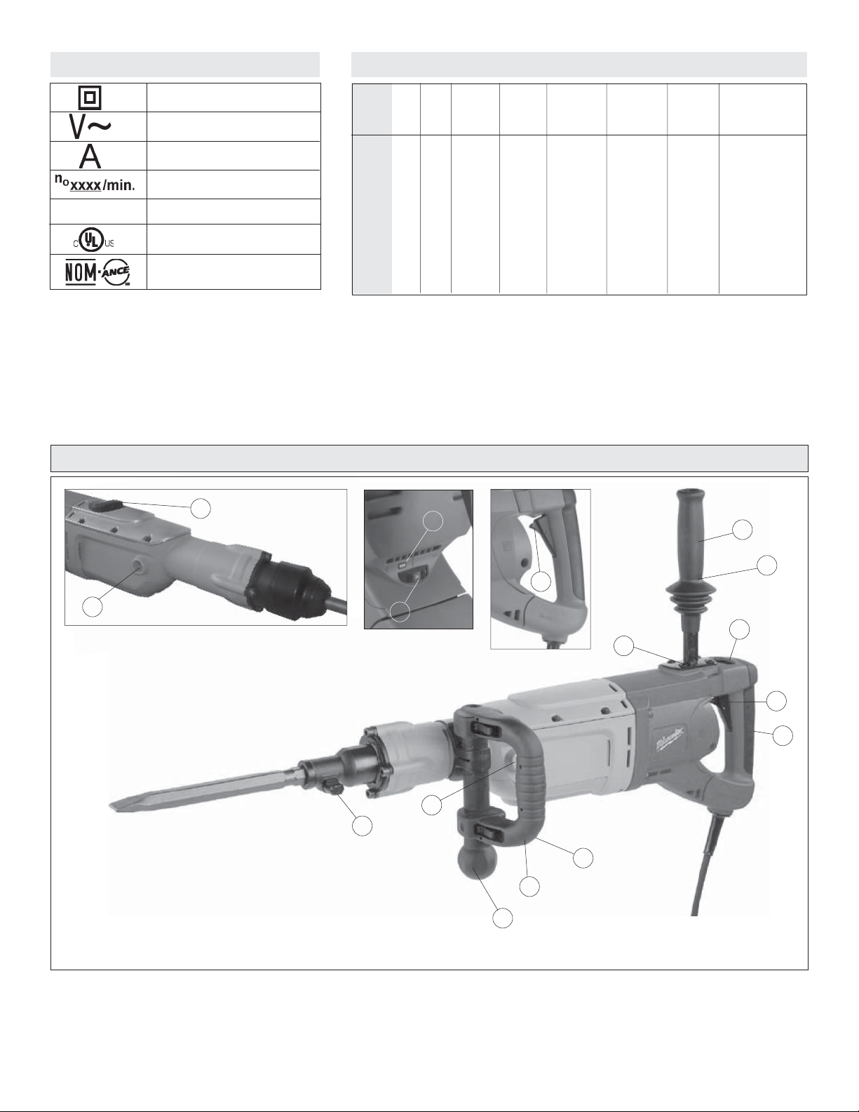
FUNCTIONAL DESCRIPTION
12
11
Cat. No. 5342-20
5
1. Vibration isolation system
2. On/Off trigger switch
3. Soft grip handle
4. Service indicator light
5. Speed control dial
6. Lock-on button (Cat. Nos. 5337-20, 5339-20 only)
9
7. Spade side handle (Cat. Nos. 5337-20, 5339-20 only)
8. Spade side handle adjusting knob (Cat. Nos. 5337-20, 5339-20 only)
9. Bit lock (Cat. Nos. 5337-20, 5340-20 only)
10. Straight side handle (must be used when hammering with rotation)
11. Straight side handle mounting positions (3 locations)
12. Action selector (Cat. No. 5339-20, 5342-20 only)
4
1
10
6
1
11
2
3
11
Cat. No. 5337-20
7
1
8
page 4
Page 5

GROUNDING EXTENSION CORDS
WARNING
Improperly connecting the grounding wire can result in the risk of
electric shock. Check with a qualifi ed electrician if you are in doubt
as to whether the outlet is properly grounded. Do not modify the
plug provided with the tool. Never remove the grounding prong
from the plug. Do not use the tool if the cord or plug is damaged. If
damaged, have it repaired by a MILWAUKEE service facility before
use. If the plug will not fi t the outlet, have a proper outlet installed
by a qualifi ed electrician.
Grounded tools require a three wire extension cord. Double insulated tools
can use either a two or three wire extension cord. As the distance from the
supply outlet increases, you must use a heavier gauge extension cord. Using extension cords with inadequately sized wire causes a serious drop in
voltage, resulting in loss of power and possible tool damage. Refer to the
table shown to determine the required minimum wire size.
The smaller the gauge number of the wire, the greater the capacity of the
cord. For example, a 14 gauge cord can carry a higher current than a 16
gauge cord. When using more than one extension cord to make up the total
length, be sure each cord contains at least the minimum wire size required. If
you are using one extension cord for more than one tool, add the nameplate
amperes and use the sum to determine the required minimum wire size.
Grounded Tools:
Tools with Three Prong Plugs
Tools marked “Grounding Required”
have a three wire cord and three
prong grounding plug. The plug must
be connected to a properly grounded
outlet (See Figure A). If the tool should
electrically malfunction or break down,
grounding provides a low resistance
path to carry electricity away from
the user, reducing the risk of electric
shock.
The grounding prong in the plug is connected through the green wire inside
the cord to the grounding system in the tool. The green wire in the cord must
be the only wire connected to the tool's grounding system and must never
be attached to an electrically “live” terminal.
Y our tool must be plugged into an appropriate outlet, properly installed and
grounded in accordance with all codes and ordinances. The plug and outlet
should look like those in Figure A.
Double Insulated Tools:
Tools with Two Prong Plugs
Tools marked “Double Insulated” do
not require grounding. They have a
special double insulation system which
satisfies OSHA requirements and
complies with the applicable standards
of Underwriters Laboratories, Inc., the
Canadian Standard Association and
the National Electrical Code. Double
Insulated tools may be used in either
of the 120 volt outlets shown in Figures
B and C.
Fig. A
Fig. B
Fig. C
Guidelines for Using Extension Cords
• If you are using an extension cord outdoors, be sure it is marked with
the suffi x “W-A” (“W” in Canada) to indicate that it is acceptable for
outdoor use.
• Be sure your extension cord is properly wired and in good electrical
condition. Always replace a damaged extension cord or have it repaired
by a qualifi ed person before using it.
• Protect your extension cords from sharp objects, excessive heat and
damp or wet areas.
Recommended Minimum Wire Gauge
Nameplate
Amperes
5.1 - 8
8.1 - 12
12.1 - 15
15.1 - 20
* Based on limiting the line voltage drop to fi ve
volts at 150% of the rated amperes.
for Extension Cords*
25'
0 - 5
16
16
14
12
10
Extension Cord Length
100'
14
12
10
10
150'
12
10
--
--
--
--
50'
16
16
14
12
10
75'
16
14
12
10
10
200'
12
--
--
--
--
READ AND SAVE ALL INSTRUCTIONS
FOR FUTURE USE.
page 5
Page 6
TOOL ASSEMBLY
WARNING
To reduce the risk of injury, always unplug tool before attaching
or removing accessories or making adjustments. Use only specifi -
cally recommended accessories. Others may be hazardous.
Adjusting the Spade Side Handle (Cat. No. 5337-20, 5339-20 only)
The spade side handle is provided on demolition hammers only. Do not use
the spade side handle on Rotary Hammers.
1. Slightly loosen the spade side handle by turning the spade side handle
adjusting knob counterclockwise.
2. Rotate the spade side handle to the desired position. The handle can be
moved to the left or right of the tool, as well as forward or backward.
3. Securely tighten the spade side handle adjusting knob.
Adjusting the Straight Side Handle
Screw the straight side handle into one of three positions (top, left side, or
right side). Tighten securely.
WARNING
To reduce the risk of injury when hammering with rotation, always
use the straight side handle when using this tool. Always brace
or hold securely.
To reduce the risk of injury when hammering with or without rotation, wear safety goggles or glasses with side shields.
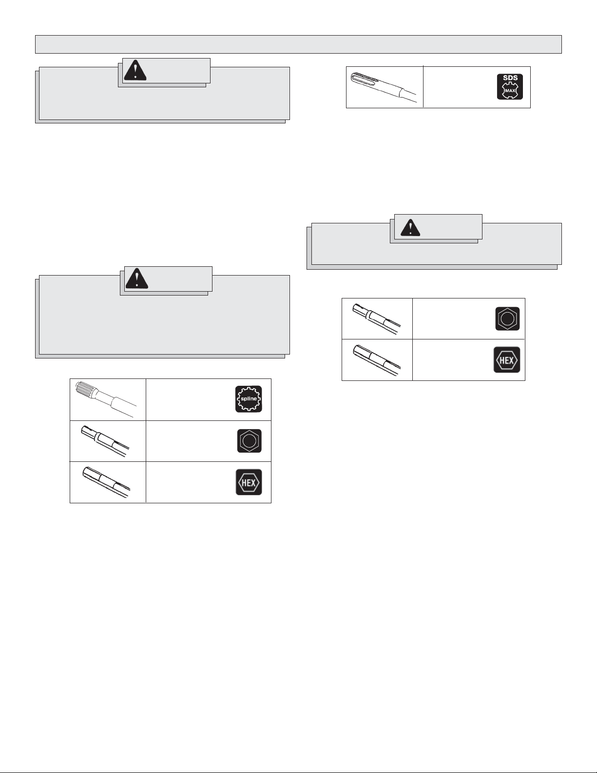
Installing Bits and Chisels
SDS Max shank
Cat. No. 5339-20,
5342-20
1. Clean and grease the bit or chisel shank.
2. Insert the bit or chisel into the nose of the tool.
3. Rotate the bit or chisel slowly until it aligns with the locking mechanism.
4. Push the bit or chisel into the tool until it locks (Fig. 2).
5. Pull on the bit or chisel to verify that it is locked into place.
6. To remove, pull the bit release collar toward the rear of the tool and
remove the bit or chisel.
WARNING
To reduce the risk of injury, use only specifi cally recommended
MILWAUKEE hammer chisels. Others may damage tool.
Installing Hammer Chisels
Round hex shank
(Cat. No. 5340-20)
Hex shank
(Cat. No. 5337-20)
Spline shank
Cat. No. 5340-20 only
Round hex shank
Cat. No. 5340-20 only
Hex shank
Cat. No. 5337-20 only
NOTE: To reduce the risk of damage to the bit lock, do not use round hex
shank bits in the 5337-20. Only use hex shank bits in this tool.
1. Clean and grease the bit or chisel shank.
2. Pull out the bit lock and rotate it 180°.
3. Insert the bit or chisel into the nose of the tool (Fig. 1)
NOTE: When using hex (on cat. no. 5337-20) or hex/round (on cat. no.
5340-20) bits or chisels, the notch in the shank must face toward the
bottom of the nosepiece of the tool.
4. Lock the bit or chisel by pulling out the bit lock and rotating it 180°.
5. Pull on the bit or chisel to verify that it is locked into place.
6. To remove, rotate the bit lock 180° and remove the bit or chisel.
NOTE: Use caution when handling hot bits and chisels.
Always clean and grease the chisel shank before inserting the chisel into the
tool. Inspect the shank to make sure it is not "mushroomed", as described
in "Maintaining Hammer Chisels". Always make sure that the chisel is in
good working condition before use.
page 6
Page 7
OPERATION
Electronic Feedback Control Circuit
These hammers have an Electronic Feedback Control Circuit (EFCC) which
helps improve the operation and life of the tool.
Feedback Control
The electronic speed control circuit allows the tool to maintain constant
speed and torque between no-load and load conditions.
Soft Start
The Soft-Start feature reduces the amount of torque reaction to the tool and
the user. This feature gradually increases the motor speed up from zero to
the speed set by the speed control dial.
WARNING
To reduce the risk of injury, wear safety goggles or glasses with
side shields. Unplug the tool before changing accessories or
making adjustments.
Selecting Speed
The speed control dial on these hammers allows the user to adjust the
rotating speed (RPM) and the impact rate (BPM) of the tool.
To change the speed, set the speed control dial to the desired setting.
• Lower speeds provide more control when starting holes and reduce
'spalling' on breakthrough. Spalling occurs when pieces of material chip
off around the drilled hole on breakthrough. When chiseling in soft or
brittle materials, use lower speeds to reduce damage to surrounding
areas of the material.
• Higher speeds provide faster penetration when drilling and chiseling in
demolition work.
Selecting Action
Cat. No. 5337-20
The cat. no. 5337-20 demolition hammer is for "hammering-only". No rotation is available. Only chisels and other "hammering-only" accessories
should be used.
Cat. No. 5339-20 (Fig. 3)
The cat. no. 5339-20 demolition hammer is for "hammering-only". No rotation
is available. The action selector is used to select the action:
Cat. No. 5340-20
The cat. no. 5340-20 rotary hammer has "hammering-only" and "hammering
with rotation", depending on the type of shank inserted into the tool.
For "hammering-only": Insert a chisel or other "hammering-only" accessory
with a 3/4" Hex with 21/32" Round shank into the nose of the tool (see
"Inserting Bits and Chisels"). The rotational drive mechanism will run but not
engage with the chisel, resulting in "hammering-only" action.
For "hammering with rotation": Insert a drill or coring bit with a spline
xxx shank into the nose of the tool (see "Inserting Bits and Chisels"). The
rotational drive mechanism engages with the bit, resulting in "hammering
with rotation" action.
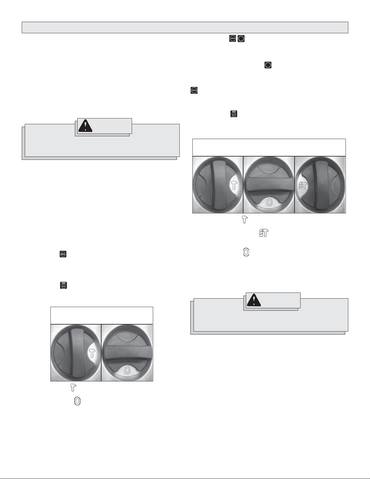
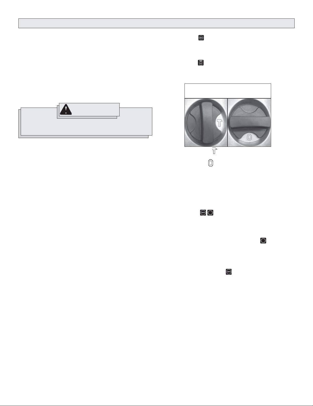
Cat. No. 5342-20 (Fig. 4)
Cat. no. 5342-20 rotary hammer has "hammering-only", "hammering with
rotation", and "chisel adjustment" settings. The action selector is used to
select the action:
Fig. 4
Hammering Only
1. Hammering only. For use with "hammering only" accessories.
Use this setting for chiseling.
2. Hammering with rotation. Use this setting for drilling holes with
drill bits. Do not use "hammering with rotation" when using chisels or
other "hammering-only" accessories.
3. Chisel adjustment. Use this setting to adjust the angle of the chisel
blade in relation to the tool. With a chisel mounted in the tool, twist
the chisel to the desired angle. Then, rotate the action selector to the
Hammering only setting for use.
NOTE: To engage the hammering mechanism, maintain pressure on the
bit/chisel. When pressure is released, hammering stops.
Chisel Adjustment
Hammering with
Rotation
WARNING
Fig. 3
Hammering Only Chisel Adjustment
1. Hammering only . For use with "hammering only" accessories. Use
this setting for chiseling.
2. Chisel adjustment. Use this setting to adjust the angle of the chisel
blade in relation to the tool. With a chisel mounted in the tool, twist
the chisel to the desired angle. Then, rotate the action selector to the
"hammering only" setting for use.
NOTE: To engage the hammering mechanism, maintain pressure on the
bit/chisel. When pressure is released, hammering stops.
To reduce the risk of injury, when using chisels or other hammering-only accessories in cat. no. 5342-20, the action selector must
be set to the "hammering only" position.
Starting and Stopping the Tool
1. To start the tool, pull the trigger.
2. To stop the tool, release the trigger.
Locking the Trigger (Cat. No. 5337-20, 5339-20 only)
The lock button on the demolition hammers holds the trigger in the "On"
position for continuous use.
1. To lock the trigger, hold in the lock button while pulling the trigger.
Release the trigger.
2. To unlock the trigger, pull the trigger and release. The lock button will
pop out.
page 7
Page 8
Cold Hammering
If the hammer is stored for a long period of time or at cold temperatures,
the lubrication may become stiff and the tool may not hammer initially or
the hammering may be weak. If this happens:
1. Insert a chisel into the tool.
2. Pull the trigger and apply the chisel against a scrap piece of concrete.
3. Turn the tool On and Off every few seconds. After 15 seconds to 2
minutes, the tool will start hammering normally. The colder the hammer
is, the longer it will take to warm up.
Operator Force
These hammers feature the Vibration Isolation System to provide the operator with comfort without sacrifi cing power or performance. The motor housing
is suspended independently from the switch handle. Insulating elements
absorb vibration when hammering and drilling.
Ideal operator force compresses the handle slightly and allows the tool to
work aggressively while the handle provides maximum vibration dampening.
Excessive operator force compresses the handle too far and reduces the
vibration dampening. Users will be able to feel the difference and should
adjust the force to the handle accordingly.
WARNING
Applying greater pressure does not increase the tool's effectiveness. If the applied working pressure is too high, the shock
absorber will be pushed together making vibration to the handle
noticeably stronger.
WARNING
To reduce the risk of injury, hold or brace securely. Always be
prepared for drill reaction when bit binds, when hole becomes
clogged, when striking embedded materials, and during hole
breakthrough.
4. Pull the trigger. Always hold the tool securely using the straight handle
and trigger handle and maintain control.
5. Use only enough pressure to hold the tool in place, engage the hammering mechanism, and prevent the tip of the bit from wandering. This
tool has been designed to achieve top performance with only moderate
pressure. Let the tool do the work.
When pressure is released, hammering stops.
6. When drilling deep holes, the speed may begin to drop off. Pull the bit
partially out of the hole while the tool is running to help clear dust.
NOTE: Do not use water to settle the dust since it will clog the bit fl utes
and tend to make the bit bind in the hole.
If a bit binds:
If the bit should bind, a built in, nonadjustable slip clutch prevents the bit
from turning when the tool is held or braced securely. If this occurs
1. Turn off and unplug the tool.
2. Free the bit from the workpiece.
3. Clear debris from the hole.
4. Begin drilling again.
WARNING
Hammering Only
1. Insert a chisel or other "hammering only" accessory into the tool (see
"Installing Bits and Chisels").
2. Position the tool on the workpiece.
3. Grasp both handles fi rmly (trigger handle and either the spade handle
or straight handle).
4. Pull the trigger. Always hold the tool securely using two handles and
maintain control.
5. Use only enough pressure to hold the tool in place, engage the hammering mechanism, and prevent the tip of the chisel from wandering.
This tool has been designed to achieve top performance with only
moderate pressure. Let the tool do the work.
NOTE: To engage the hammering mechanism, maintain pressure on
the bit/chisel. When pressure is released, hammering stops.
6. When chiseling or chipping, hold the tool at an angle to the work area.
For best performance, work from a corner or close the edge of the work
and break off a small area at a time.
If a hammer iron gets stuck:
1. Unplug the tool.
2. Pull out bit lock and rotate it 180°.
3. Pull the tool off of the stuck accessory.
4. Remove the accessory from the workpiece.
Hammering with Rotation
1. Insert a drill or coring bit into the tool (see "Installing Bits and Chisels").
2. Position the tool on the workpiece.
3. Grasp both handles fi rmly (trigger handle and straight handle).
Use MILWAUKEE core bits Cat. No. 48-20-5125 through 48-20-5165.
Do not use LHS (Large Hole System) Components with rotary hammers 5340-20 and 5342-20. The bits could fail, breaking apart at the
threaded stud and causing injury and property damage.
Using Rotary Percussion Core Bits (Fig. 5 - 7)
Core bits are useful for drilling larger holes for conduit and pipe.
MILWAUKEE Heavy-Duty Core Bits have heat-treated steel bodies with
durable carbide tips. These core bits are specially designed for fast, accurate
drilling with combined hammering and rotary action.
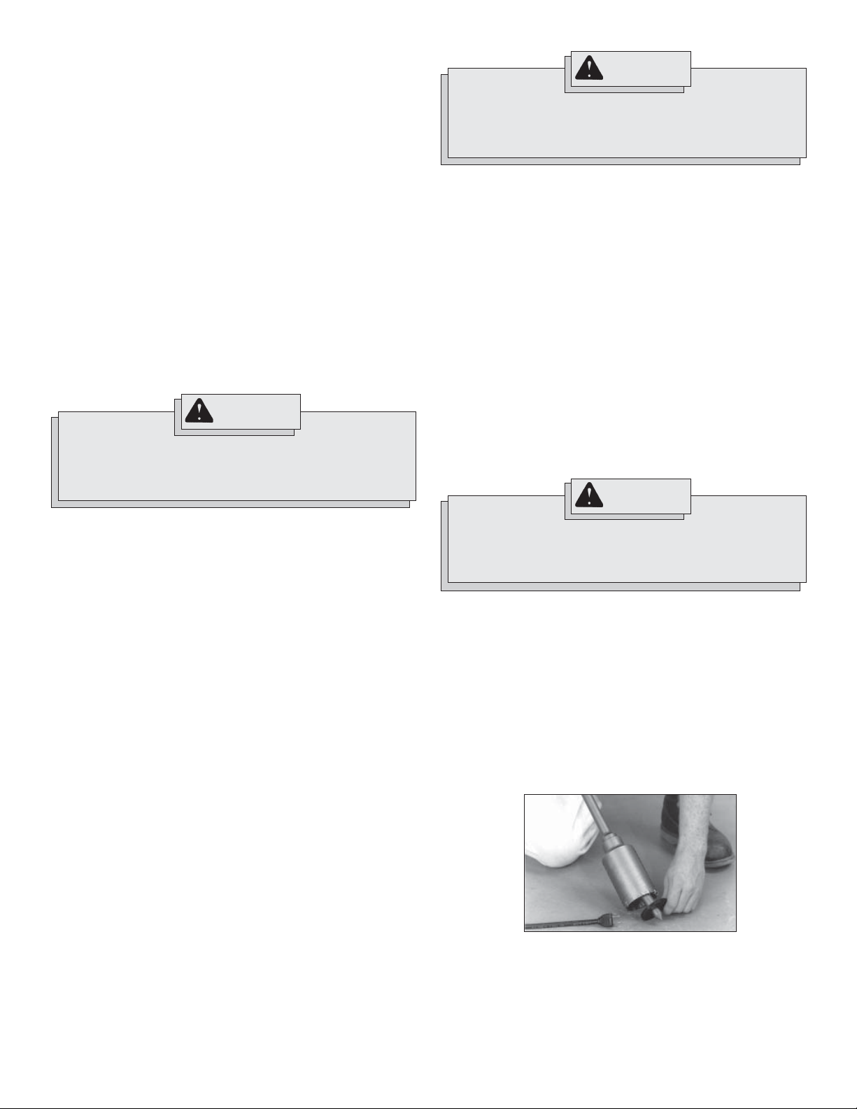
1. Clean and lubricate the threads on the adapter and core bit to make
later removal easier. Screw the threaded end of the adapter into the
rear of the core bit.
2. Push the guide plate onto the pointed end of the center pin. Insert the
center pin and guide plate assembly into the core bit. Be sure the small
end of the center pin is securely placed into the hole in the center of
the core bit (Fig. 5).
Fig. 5
3. Insert the adapter into the nose of the tool (see “Installing Bits and
Chisels”. Set the action selector to the hammering-with-rotation
setting.
page 8
Page 9
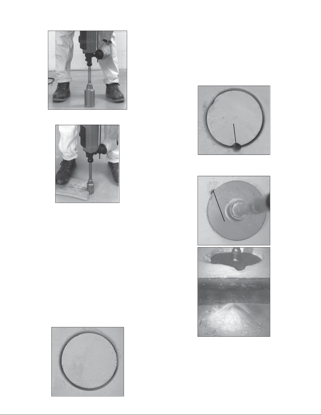
4. Press the center pin fi rmly against your center mark, hold the tool fi rmly
and pull the trigger (Fig. 6).
Fig. 6
3. Remove the bit from the tool.
4. Install a standard fl uted bit, approximately 7/8" in diameter, onto the
tool.
5. Drill a perpendicular hole through the kerf of the large hole (Fig. 9).
• Depending on the location of the work, the hole should either break
through the other side of the hole/fl oor or extend 4"-5" past the end of
the workpiece (such as into the dirt below a concrete slab).
• If dust builds up in the hole, vacuum it out and continue drilling.
• If drilling through a wall, the hole for dust should be drilled on the lowest
part of the large hole kerf (Fig. 9) as the dust will fall there when drilling
and can be evacuated more easily.
Fig. 9
NOTE: If a center pin and guide plate are not available, use a template
or notched board to start the hole (Fig. 7).
Fig. 7
5. After drilling to about the depth of the core bit teeth, remove the center
pin and guide plate from the core bit. Resume drilling.
6. To change the core bit, hold the tool upwards, pointing it away from
your body, and run the tool allowing rotation and impacting for about
fi ve seconds to loosen the core bit from the adapter shank.
NOTE: To make deeper holes, remove the core bit, break and remove
the core. Resume drilling. When drilling long or deep holes, after each
inch of penetration pull the bit partially out of the hole while the tool is
running, to help clear dust from the bit fl utes. Dust can clog the bit fl utes
and can make the bit bind in the hole. If this occurs, stop the tool, free
the bit and begin again.
Drill a hole through
the work.
6. Reinstall the core bit and continue drilling (Fig. 10 & 11). Dust and debris
will fall through the hole and optimize the cutting ability of the bit.
Fig. 10
Dust and debris
will fall through
the hole.
Top view
Fig. 11
Drilling Large Diameter Holes with Core Bits (Fig. 8-13)
When drilling holes with large diameter core bits, dust may build up in the
cut and can cause the tool to stall, bind, or cut slowly. By creating an opening for the dust to escape, drilling time, bit stress, and tool stress can be
reduced.
1. Start the cut as normal.
2. Once the bit is fi rmly established in the cut (about 1/4" deep), remove
the bit from the cut (Fig. 8).
Fig. 8
Cut approximately
1/4" deep with a core
bit.
Side view
of slab
page 9
Page 10
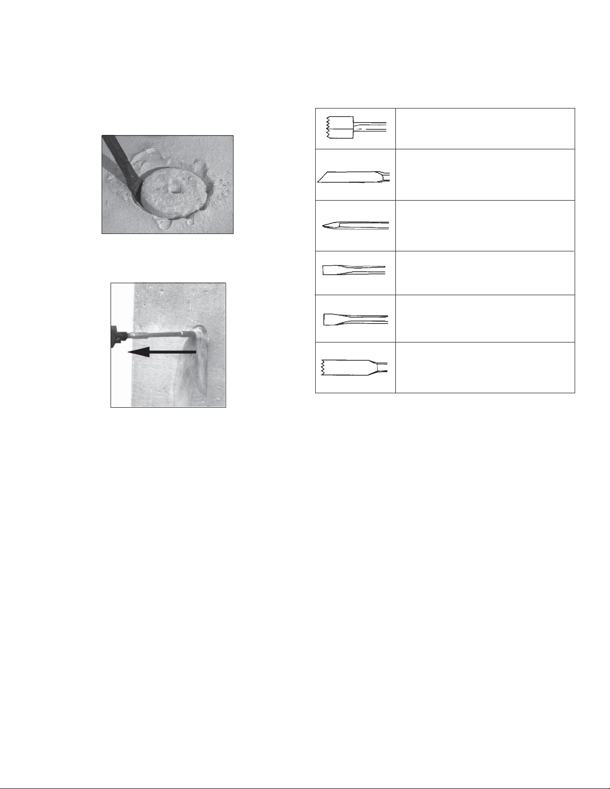
7. For core bits, once the maximum core bit depth is drilled, the core must
be broken and removed.
• Install a chisel bit.
• Place the chisel into the hole kerf (Fig. 12).
• Chisel down into the kerf at several points until the core is loose or
broken.
• Remove the core and vacuum/remove any remaining dust and debris.
• Install the core bit and continue the cut.
Fig.
NOTE: If unable to drill a hole in the kerf, pull back on the bit with the ham-
mer running (Fig. 13). This will remove some of the dust and debris from
the cut. Repeat this for every inch of drilling. If necessary, vacuum dust and
debris from the cut and surrounding area.
Fig. 13
Pull bit out as far
as possible once
or twice per inch
drilled.
Chiseling and Chipping
These MILWAUKEE Hammers may be used for chipping and chiseling.
When chiseling, hold the tool at an angle to the workpiece. Work from a
corner or close to the edge of the workpiece, breaking off one small area
at a time rather than attempting too large an area.
A variety of accessories are available.
Bushing Tools
Used to surface concrete.
Mortar Cutting Chisels (Seam Tools)
For removing old mortar for tuck pointing or
caulking.
Bull Points
For demolition work and starting holes in
concrete slabs.
Flat Chisels
For edging, chipping or channeling.
Scaling Chisels
For removing weld spatter or scale and cutting straight lines.
Slotting Chisel
For slotting and cutting between drilled holes
in concrete and masonry.
page 10
Page 11

MAINTENANCE
ACCESSORIES
WARNING
To reduce the risk of injury, always unplug your tool before performing any maintenance. Never disassemble the tool or try to do
any rewiring on the tool's electrical system. Contact a MILW AUKEE
service facility for ALL repairs.
Maintaining Tools
Keep your tool in good repair by adopting a regular maintenance program. Before use, examine the general condition of your tool. Inspect
guards, switches, tool cord set and extension cord for damage. Check
for loose screws, misalignment, binding of moving parts, improper
mounting, broken parts and any other condition that may affect its safe
operation. If abnormal noise or vibration occurs, turn the tool off immediately and have the problem corrected before further use. Do not
use a damaged tool. Tag damaged tools “DO NOT USE” until repaired
(see “Repairs”).
Under normal conditions, relubrication is not necessary until the motor
brushes need to be replaced. After six months to one year, depending on
use, return your tool to the nearest MILWAUKEE service facility for the
following:
• Lubrication
• Brush inspection and replacement
• Mechanical inspection and cleaning (gears, spindles, bearings,
housing, etc.)
• Electrical inspection (switch, cord, armature, etc.)
• Testing to assure proper mechanical and electrical operation
Maintaining Hammer Chisels
Through normal use, the shank of the chisel can "mushroom" over and cause
the chisel to become stuck inside the hammer. To prevent this from happening, periodically remove the chisel from the tool and inspect the shank. If the
shank starts to "mushroom", have the chisel refurbished or replaced.
WARNING
To reduce the risk of injury, always unplug the tool before attaching or removing accessories. Use only specifi cally recommended
accessories. Others may be hazardous.
For a complete listing of accessories refer to your MILWAUKEE Electric Tool catalog or go on-line to www.milwaukeetool.com. To obtain a
catalog, contact your local distributor or a service center.
Thick Wall Carbide-Tipped Core Bits
Core body with Guide Plate and Centering Pin
Diameter Drilling Depth Cat.No.
1-1/2" 4-1/16" 48-20-5125
1-3/4" 4-1/16" 48-20-5130
2" 4-1/16" 48-20-5135
2-1/2" 4-1/16" 48-20-5140
3" 4-1/16" 48-20-5145
3-1/2" 4-1/16" 48-20-5150
4" 4-1/16" 48-20-5155
5" 4-1/16" 48-20-5160
6" 4-1/16" 48-20-5165
NOTE: Use MILWAUKEE core bits Cat. No. 48-20-5125 through 48-20-5165.
Do not use LHS (Large Hole System) Components with rotary hammers
5340-20 and 5342-20. The bits could fail, breaking apart at the threaded
stud and causing injury and property damage.
Brush Replacement
These MILWAUKEE hammers are will automatically shut off when the
brushes need to be replaced. Return your tool to the nearest MILWAUKEE
service facility for repairs.
Service Indicator Light
These MILWAUKEE Hammers feature a service indicator light. When the
red light turns on, the tool is in need of servicing. Return your tool to the
nearest MILWAUKEE service facility for service.
NOTE: When the service light comes on, the tool will continue to run for a
few hours and then the motor will shut off.
WARNING
To reduce the risk of injury, electric shock and damage to the tool,
never immerse your tool in liquid or allow a liquid to fl ow inside
the tool.
Cleaning
Clean dust and debris from vents. Keep the tool handles clean, dry and
free of oil or grease. Use only mild soap and a damp cloth to clean your
tool since certain cleaning agents and solvents are harmful to plastics and
other insulated parts. Some of these include: gasoline, turpentine, lacquer
thinner, paint thinner, chlorinated cleaning solvents, ammonia and household detergents containing ammonia. Never use fl ammable or combustible
solvents around tools.
Repairs
If your tool is damaged, return the entire tool to the nearest service center.
FIVE YEAR TOOL LIMITED WARRANTY
Every MILWAUKEE tool is tested before leaving the factory and is warranted to be free from defects in material and workmanship. MILWAUKEE
will repair or replace (at MILWAUKEE’s discretion), without charge, any
tool (including battery chargers) which examination proves to be defective
in material or workmanship from fi ve (5) years after the date of purchase.
Return the tool and a copy of the purchase receipt or other proof of purchase to a MILWAUKEE Factory Service/Sales Support Branch location or
MILWAUKEE Authorized Service Station, freight prepaid and insured. This
warranty does not cover damage from repairs made or attempted by other
than MILWAUKEE authorized personnel, abuse, normal wear and tear, lack
of maintenance, or accidents.
Battery Packs, Flashlights, and Radios are warranted for one (1) year from
the date of purchase.
THE REPAIR AND REPLACEMENT REMEDIES DESCRIBED HEREIN ARE
EXCLUSIVE. IN NO EVENT SHALL MILWAUKEE BE LIABLE FOR ANY
INCIDENTAL, SPECIAL, OR CONSEQUENTIAL DAMAGES, INCLUDING
LOSS OF PROFITS.
THIS WARRANTY IS EXCLUSIVE AND IN LIEU OF ALL OTHER WARRANTIES, OR CONDITIONS, WRITTEN OR ORAL, EXPRESSED OR
IMPLIED FOR MERCHANTABLILITY OR FITNESS FOR PARTICULAR
USE OR PURPOSE.
This warranty gives you specifi c legal rights. You may also have other rights
that vary from state to state and province to province. In those states that
do not allow the exclusion of implied warranties or limitation of incidental
or consequential damages, the above limitations or exclusions may not
apply to you. This warranty applies to the United States, Canada, and
page 11
Page 12

RÈGLES GÉNÉRALES DE SÉCURITÉ POUR LES OUTILS ÉLECTRIQUE
AVERTISSEMENT
LIRE SOIGNEUSEMENT TOUTES LES INSTRUCTIONS
Le non respect des instructions ci-après peut entraîner des chocs électriques, des
incendies et/ou des blessures graves. Le terme «outil électrique» fi gurant dans les
avertissements ci-dessous renvoie à l’outil électrique à alimentation par le réseau
(à cordon) ou par batterie (sans fi l).
CONSERVER CES INSTRUCTIONS
SÉCURITÉ DU LIEU DE TRAVAIL
1. Maintenir la zone de travail propre et bien éclairée. Les zones
encombrées ou mal éclairées sont favorables aux accidents.
2. Ne pas utiliser d’outil électrique dans une atmosphère explosive,
telle qu’en en présence de liquides, de gaz ou de poussières in-
fl ammables. Les outils électriques génèrent des étincelles qui peuvent
enfl ammer les poussières ou les fumées.
3. Tenir les enfants et les personnes non autorisées à l’écart pendant
le fonctionnement d’un outil électrique. Un manque d’attention de
l’opérateur risque de lui faire perdre le contrôle de l’outil.
SÉCURITÉ ÉLECTRIQUE
4. La fiche de l’outil électrique doit correspondre à la prise
d’alimentation. Ne jamais modifi er la fi che d’une manière quel-
conque. Ne pas utiliser d’adaptateur avec les outils électriques
mis à la terre (à la masse). Des fi ches non modifi ées et des prises
d’alimentation assorties réduisent le risque de choc électrique.
5. Éviter tout contact corporel avec des surfaces reliées à la masse ou
à la terre telles que tuyaux, radiateurs, cuisinières et réfrigérateurs.
Un risque de choc électrique plus élevé existe si le corps est relié à la
masse ou à la terre.
6. Ne pas exposer les outils électriques à la pluie ou à l’humidité. Le
risque de choc électrique augmente si de l’eau s’infi ltre dans un outil
électrique.
7. Prendre soin du cordon. Ne jamais utiliser le cordon pour trans-
porter, tirer ou débrancher l’outil électrique. T enir le cordon à l’écart
de la chaleur, des huiles, des arêtes coupantes ou des pièces en
mouvement. Un cordon endommagé ou emmêlé présente un risque
accru de choc électrique.
8. Se procurer un cordon d’alimentation approprié en cas
d’utilisation d’un outil électrique à l’extérieur. L’utilisation d’un
cordon d’alimentation pour usage extérieur réduit le risque de choc
électrique.
SÉCURITÉ INDIVIDUELLE
9. Être sur ses gardes, être attentif et faire preuve de bon sens en
utilisant un outil électrique. Ne pas utiliser un outil électrique en
cas de fatigue ou sous l’infl uence de drogues, d’alcool ou de
médicaments. Un instant d’inattention lors de l’utilisation d’un outil
électrique peut entraîner des blessures graves.
10. Utiliser un équipement de sécurité. Toujours porter des lunettes de
protection. Un équipement de sécurité comprenant masque anti-poussière, chaussures de sécurité anti-dérapantes, casque ou dispositif de
protection anti-bruit peut, dans les circonstances appropriées, réduire
le risque de blessure.
11. Éviter tout démarrage accidentel de l’outil. S’assurer que le com-
mutateur est en position OFF (Arrêt) avant de brancher l’outil. Le
port de l’outil avec un doigt sur le commutateur ou son branchement
avec le commutateur en position ON (Marche) sont favorables aux
accidents.
12. Retirer toute clé de réglage avant de mettre l’outil sous tension.
Une clé laissée attachée sur une pièce mobile de l’outil électrique peut
entraîner des blessures.
13. Ne pas travailler à bout de bras. Bien garder un bon équilibre à tout
instant. Ceci permet de mieux préserver la maîtrise de l’outil électrique
dans des situations imprévues.
page 12
14. Porter des vêtements adéquats. Ne pas porter de vêtements amples
ni de bijoux. Ne pas approcher les cheveux, vêtements et gants
des pièces en mouvement. Les vêtements amples, les bijoux ou les
cheveux longs risquent d’être happés par les pièces en mouvement.
15. Si des dispositifs sont prévus pour l’extraction et la récupération
des poussières, vérifi er qu’ils sont connectés et utilisés correcte-
ment. L’utilisation de ces dispositifs peut réduire les risques liés aux
poussières.
UTILISA TION ET ENTRETIEN DE L’OUTIL ÉLECTRIQUE
16. Ne pas forcer l’outil électrique. Utiliser l’outil électrique approprié
à l’application considérée. L’outil électrique adapté au projet consi-
déré produira de meilleurs résultats, dans des conditions de sécurité
meilleures, à la vitesse pour laquelle il a été conçu.
17. Ne pas utiliser l’outil électrique si le commutateur ne le met pas
sous ou hors tension. Tout outil électrique dont le commutateur de
marche-arrêt est inopérant est dangereux et doit être réparé.
18. Débrancher la fi che de la prise d’alimentation et/ou la batterie
de l’outil électrique avant d’effectuer des réglages, de changer
d’accessoires ou de ranger l’outil. De telles mesures de sécurité
préventive réduisent le risque de mettre l’outil en marche accidentellement.
19. Ranger les outils électriques inutilisés hors de la portée des
enfants et ne pas laisser des personnes qui connaissent mal les
outils électriques ou ces instructions utiliser ces outils. Les outils
électriques sont dangereux dans les mains d’utilisateurs non formés à
leur usage.
20. Entretien des outils électriques. S’assurer de l’absence de tout
désalignement ou de grippage des pièces mobiles, de toute rupture
de pièce ou de toute autre condition qui pourrait affecter le bon
fonctionnement de l’outil électrique. En cas de dommages, faire
réparer l’outil avant de l’utiliser de nouveau. Les outils électriques
mal entretenus sont à la source de nombreux accidents.
21. Garder les outils de coupe affûtés et propres. Les outils de coupe
correctement entretenus et bien affûtés risquent moins de se gripper
et sont plus faciles à manier.
22. Utiliser cet outil électrique, les accessoires, les mèches, etc.
conformément à ces instructions et de la façon prévue pour ce
type particulier d’outil électrique, tout en prenant en compte les
conditions de travail et le type de projet considérés. L’utilisation de
cet outil électrique pour un usage autre que l’usage prévu peut créer
des situations dangereuses.
ENTRETIEN
23. Faire effectuer l’entretien de l’outil électrique par un technicien
qualifi é qui n’utilisera que des pièces de rechange identiques. La
sécurité d’utilisation de l’outil en sera préservée.
RÈGLES DE SÉCURITÉ PARTICULIÈRE
1. Tenir l’outil par les surfaces de prise isolées si, au cours des
travaux, l’outil de coupe risque d’entrer en contact avec des fi ls
cachés ou avec son propre cordon. Le contact avec un fi l sous ten-
sion met les parties métalliques exposées de l’outil sous tension, ce
qui infl igera un choc électrique à l’opérateur.
2. Entretenez les étiquettes et marqies di fabricant. Les indications
qu'elles contiennent sont précieuses. Si elles deviennent illisibles ou
se détachent, faites-les remplacer gratuitement à un centre de service
MILWAUKEE accrédité.
Page 13

3. AVERTISSEMENT! La poussière degage par perçage, sclage, perçage
et autres travaux de construction contient des substances chimiques
reconnues comme pouvant causer le cancer, des malformations congénitales ou d’autres troubles de reproduction. Voici quelques exemples
de telles substances
• Le plomb contenu dans la peinture au plomb.
• Le silice cristallin contenu dans la brique, le béton et divers produits de
maçonnerie.
• L’arsenic et le chrome servant au traitement chimique du bois.
Les risque associés à l’exposition à ces substances varient, dépendant
de la fréquence des travaux. Afi n de minimiser l’exposition à ces sub-
stances chimiques, assurez-vous de travailler dans un endroit bien aéré
et d’utiliser de l’equipement de sécurité tel un masque antipoussière
spécifi quement conçu pour la fi ltration de particules microscopiques.
4. Porter des protège-oreilles. Une exposition au bruit peut provoquer
une perte auditive.
5. Utiliser les poignées auxiliaires fournies avec l’outil. Une perte de
contrôle peut provoquer des blessures.
Specifi cations
No de
cat.
5337-20
5337-21
5339-20
5339-21
5340-20
5340-21
5342-20
5342-21
Volts
CA
120
120
120
120
120
120
120
120
Amps
14
14
14
14
15
15
15
15
T/Min à
vide
--
--
--
--
125 - 250
125 - 250
125 - 250
125 - 250
Coups/
975-1 950*
975-1 950*
975-1 950*
975-1 950*
975-1 950*
975-1 950*
975-1 950*
975-1 950*
Diamètre maxi de la
mèche de perçage à
Min.
Cannelure de 51 mm
Cannelure de 51 mm
SDS-Max de 51 mm
SDS-Max de 51 mm
percussion
--
--
--
-(2")
(2")
(2")
(2")
* EFCC - Le circuit électronique de contrôle de la rétroaction maintient une vitesse constante quelles que
soient les variations de la charge.
†
Utiliser les trépans carottiers MILWAUKEE No de cat. 48-20-5125 à 48-20-5165. Ne pas utiliser les com-
posants LHS (systèmes pour grands orifi ces) avec les marteaux rotatifs 5340-20 et 5342-20. Les mèches
Diamètre maxi du
trépan carottier à
percussion
152 mm† (6")
152 mm† (6")
152 mm† (6")
152 mm† (6")
†
--
--
--
--
Ciseaux
Voir
« Cisèlement
et
burinage »
Type de queue
de ciseau
Hexagonal de 3/4 po
Hexagonal de 3/4 po
SDS-Max
SDS-Max
Hexagonal de 3/4 po
et rond de 21/32 po
Hexagonal de 3/4 po
et rond de 21/32 po
SDS-Max
SDS-Max
DESCRIPTION FONCTIONNELLE
12
No de cat. 5342-20
4
BPM
Pictographie
Double Isolation
Courant alternatif
Ampères
Tours-minute à
vide (RPM)
Coups/Min.
Underwriters
Laboratories, Inc.
Inscription mexicaine
d’approbation
1
10
11
1. Système d’isolation contre les vibrations
2. Gâchette marche/arrêt
3. Poignée
4. Témoin lumineux de fonctionnement
5. Cadran de réglage de la vitesse
6. Bouton de blocage (No de cat. 5337-20, 5339-20
uniquement)
9
7. Poignée latérale courbe (No de cat. 5337-20, 5339-20 uniq.)
8. Molette de réglage de la poignée latérale (No de cat. 5337-20,
5339-20 uniquement)
9. Mandrin (No de cat. 5337-20, 5340-20 uniquement)
10. Poignée latérale droite (à utiliser avec le martelage rotatif)
11. Positions de montage de la poignée latérale droite (3 positions)
12. Sélecteur de mode (No de cat. 5339-20, 5342-20 uniquement)
6
5
1
11
2
3
11
No de cat. 5337-20
7
1
8
page 13
Page 14

MISE À LA TERRE
CORDONS DE RALLONGE
AVERTISSEMENT
Si le fi l de mise à la terre est incorrectement raccordé, il peut en
résulter des risques de choc électrique. Si vous n’êtes pas certain que la prise dont vous vous servez est correctement mise à
la terre, faites-la vérifi er par un électricien. N’altérez pas la fi che
du cordon de l’outil. N’enlevez pas de la fi che, la dent qui sert à
la mise à la terre. N’employez pas l’outil si le cordon ou la fi che
sont en mauvais état. Si tel est le cas, faites-les réparer dans un
centre-service MILWAUKEE accrédité avant de vous en servir. Si
la fi che du cordon ne s’adapte pas à la prise, faites remplacer la
prise par un électricien.
Outils mis à la terre :
Outils pourvus d’une fi che de cordon à trois dents
Les outils marqués « Mise à la terre
requise » sont pourvus d’un cordon à
trois fi ls dont la fi che a trois dents. La
fi che du cordon doit être branchée sur
une prise correctement mise à la terre
(voir Figure A). De cette façon, si une
défectuosité dans le circuit électrique
de l’outil survient, le relais à la terre
fournira un conducteur à faible résistance pour décharger le courant et
protéger l’utilisateur contre les risques
de choc électrique.
La dent de mise à la terre de la fi che est reliée au système de mise à la
terre de l’outil via le fi l vert du cordon. Le fi l vert du cordon doit être le seul fi l
raccordé à un bout au système de mise à la terre de l’outil et son autre extrémité ne doit jamais être raccordée à une borne sous tension électrique.
Votre outil doit être branché sur une prise appropriée, correctement installée et mise à la terre conformément aux codes et ordonnances en vigueur.
La fi che du cordon et la prise de courant doivent être semblables à celles
de la Figure A.
Outils à double isolation :
Outils pourvus d’une fi che de cordon à deux dents
Les outils marqués « Double
Isolation » n’ont pas besoin d’être
raccordés à la terre. Ils sont pourvus
d’une double isolation conforme eux
exigences de l’OSHA et satisfont aux
normes de l’Underwriters Laboratories, Inc., de l’Association canadienne
de normalisation (ACNOR) et du
« National Electrical Code » (code
national de l’électricité). Les outils à
double isolation peuvent être branchés
sur n’importe laquelle des prises à 120
volt illustrées ci-contre Figure B et C.
Fig. A
Fig. B
Fig. C
Si l’emploi d’un cordon de rallonge est nécessaire, un cordon à trois fi ls doit
être employé pour les outils mis à la terre. Pour les outils à double isolation,
on peut employer indifféremment un cordon de rallonge à deux ou trois fi ls.
Plus la longueur du cordron entre l’outil et la prise de courant est grande,
plus le calibre du cordon doit être élevé. L’utilisation d’un cordon de rallonge
incorrectement calibré entraîne une chute de voltage résultant en une perte
de puissance qui risque de détériorer l’outil. Reportez-vous au tableau cicontre pour déterminer le calibre minimum du cordon.
Moins le calibre du fi l est élevé, plus sa conductivité est bonne. Par exemple,
un cordon de calibre 14 a une meilleure conductivité qu’un cordon de calibre 16. Lorsque vous utilisez plus d’une rallonge pour couvrir la distance,
assurez-vous que chaque cordon possède le calibre minimum requis. Si
vous utilisez un seul cordon pour brancher plusieurs outils, additionnez le
chiffre d’intensité (ampères) inscrit sur la fi che signalétique de chaque outil
pour obtenir le calibre minimal requis pour le cordon.
Directives pour l’emploi des cordons de rallonge
• Si vous utilisez une rallonge à l’extérieur, assurez-vous qu’elle est
marquée des sigles « W-A » (« W » au Canada) indiquant qu’elle est
adéquate pour usage extérieur.
• Assurez-vous que le cordon de rallonge est correctement câblé et
en bonne condition. Remplacez tout cordon derallonge détérioré ou
faites-le remettre en état par une personne compétente avant de vous
en servir.
• Tenez votre cordon de rallonge à l’écart des objets ranchants, des
sources de grande chaleur et des endroits humides ou mouillés.
Calibres minimaux recommandés pour les
Fiche
signalétique
Ampères
0 - 5,0
5,1 - 8,0
8,1 - 12,0
12,1 - 15,0
15,1 - 20,0
* Basé sur sur une chute de voltage limite de 5
volts à 150% de l’intensité moyenne de courant.
cordons de rallonge*
Longueur du cordon de rallonge (m)
30,4
14
12
10
10
45,7
60,9
12
10
--
--
--
--
7,6
16
16
14
12
10
15,2
16
16
14
12
10
22,8
16
14
12
10
10
12
--
--
--
--
LISEZ ATTENTIVEMENT CES INSTRUCTIONS
ET CONSERVEZ-LES POUR LES
CONSUL TER AU BESOIN.
page 14
Page 15

MONTAGE DE L'OUTIL
AVERTISSEMENT
Pour minimiser les risques de blessures, débranchez toujours
l’outil avant d’y faire des réglages, d’y attacher ou d’en enlever
les accessoires. L’usage d’accessoires autres que ceux qui
sont spécifi quement recommandés pour cet outil peut com-
porter des risques.
Réglage de la poignée latérale courbe (No de cat. 5337-20,
5339-20 uniquement)
Seuls les marteaux de démolition sont équipés d’une poignée latérale
courbe. N’utilisez pas la poignée latérale avec marteaux rotatifs.
1. Desserrez légèrement la poignée latérale en faisant tourner la molette
de réglage de la poignée dans le sens anti-horaire.
2. Faites tourner la poignée latérale jusqu’à la position désirée. Vous
pouvez déplacer la poignée vers la gauche, vers la droite, vers l’avant
ou vers l’arrière de l’outil.
3. Resserrez la molette de réglage de la poignée latérale.
Réglage de la poignée latérale droite
Visser la poignée latérale droite sur une des trois positions (supérieure,
latérale gauche ou latérale droite). Resserrez fermement.
AVERTISSEMENT
Pour minimiser les risques de blessures lors du martelage
avec rotation, veuillez toujours utiliser la poignée latérale droite
lorsque vous utilisez cet outil. Maintenez-le fermement.
Pour minimiser les risques de blessures lors du martelage avec
ou sans rotation, portez des lunettes étanches ou des lunettes
à protection latérale.
Installation des mèches et ces ciseaux
Queue SDS Max
No de cat. 5339-20,
5342-20
1. Nettoyez et graissez la queue de la mèche ou du ciseau.
2. Introduisez la mèche ou le ciseau dans l’embout de l’outil.
3. Faites tourner lentement la mèche ou le ciseau jusqu’à ce qu’il soit
aligné avec le mécanisme de blocage.
4. Enfoncez la mèche ou le ciseau jusqu’à ce qu’ils s’enclenchent dans
l’outil (Fig. 2).
5. Tirez sur la mèche ou sur le ciseau pour vérifier qu’il est
fermement bloqué.
6. Pour les retirer, tirez sur le collier de déblocage de la mèche vers l’arrière
de l’outil, puis enlevez la mèche ou le ciseau.
AVERTISSEMENT
Pour minimiser les risques de blessures, utilisez les ciseaux pour
marteaux spécialement recommandés par MILWAUKEE. Les cis-
eaux d’autres marques pourraient endommager l’outil.
Installation des ciseaux pour marteau
Queue hexagonale
arrondie
(No de cat. 5340-20)
Queue hexagonale
(No de cat. 5337-
Queue cannelée
No de cat. 5340-20
uniquement
Queue hexagonale
arrondie
No de cat. 5340-20
uniquement
Queue hexagonale
No de cat. 5337-20
uniquement
N.B. : Pour minimiser les risques d’endommagement du mandrin, n’utilisez
pas de mèches à queue hexagonale arrondie sur le 5337-20. Sur cet outil,
n’utilisez que des mèches à queue hexagonale.
1. Nettoyez et graissez la queue de la mèche ou du ciseau.
2. Tirez sur le mandrin et faites-le tourner de 180°.
3. Introduisez la mèche ou le ciseau dans l’embout de l’outil (Fig. 1).
N.B. : Lors de l’utilisation de mèches ou de ciseaux hexagonaux
(sur la No de cat. 5337-20) ou hexagonaux/ronds (sur le No de cat.
5340-20), l’encoche de la queue doit être orientée vers l’embout
de l’outil.
4. Serrez la mèche ou le ciseau en tirant sur le mandrin et en le faisant
tourner de 180°.
5. Tirez sur la mèche ou sur le ciseau pour vérifi er qu’il est fermement
bloqué.
6. Pour les retirer, tournez le mandrin de 180° et retirez la mèche
ou le ciseau.
NOTA : Soyez prudent lors de la manipulation de mèches et de ciseaux
chauds.
Nettoyez et graissez toujours la queue du ciseau avant de l’introduire
dans l’outil. Examinez la queue pour vous assurer qu’elle ne présente pas
une forme de champignon tel que décrit sous la rubrique « Entretien des
ciseaux pour marteau ». Assurez-vous toujours que le ciseau est en bon
état avant de l’utiliser.
page 15
Page 16
MANIEMENT
Circuit de contrôle électronique de la rétroaction
Ces marteaux disposent d’un circuit électronique de contrôle de la
rétroaction (EFCC) qui permet d’améliorer l’utilisation et la durée de
service de l’outil.
Contrôle de la rétroaction
Le circuit électronique de contrôle de la vitesse maintient une vitesse et un
couple constants de l’outil, avec ou sans charge.
Démarrage sans à-coups
La fonction de démarrage sans à-coups réduit le couple appliqué sur l’outil
et subi par l’utilisateur. Cette fonction augmente progressivement la vitesse
du moteur de zéro jusqu’à la vitesse sélectionnée sur le cadran de réglage
de la vitesse.
AVERTISSEMENT
Pour minimiser les risques de blessures, portez des lunettes à
coques latérales. Débranchez l’outil avant de changer les accessoires ou d’effectuer des réglages.
Sélection de la vitesse
Le cadran de réglage de la vitesse de ces marteaux permet à l’utilisateur
de régler la vitesse de rotation (tr/mn) et la vitesse d’impact (coups par
minute) de l’outil.
Pour modifi er la vitesse, réglez le cadran de réglage de la vitesse selon
vos besoins.
• Une vitesse réduite garantit un meilleur contrôle lorsque vous commencez un orifi ce et elle réduit l’effet d’écaillage. L’écaillage se produit
lorsque des morceaux de matériau s’émiettent autour de l’orifi ce perforé.
Lors du burinage de matériaux fragiles et cassants, réduisez la vitesse
pour éviter d’endommager les zones adjacentes.
• Une grande vitesse permet de perforer et buriner plus rapidement lors
des travaux de démolition.
Sélection du mode de travail
No de cat. 5337-20
Le marteau de démolition No de cat. 5337-20 est conçu pour
« martelage uniquement ». La rotation n’est pas disponible. N’utilisez que
des ciseaux ou d’autres accessoires pour « martelage uniquement ».
No de cat. 5339-20 (Fig. 3)
Le marteau de démolition No de cat. 5339-20 est conçu pour « martelage
uniquement ». La rotation n’est pas disponible. Utilisez le sélecteur de mode
pour choisir le type d’opération :
Fig. 3
Martelage
uniquement
1. Martelage uniquement. Pour l’utilisation des accessoires pour « mar-
telage uniquement ». Utilisez cette confi guration pour le burinage.
2. Réglage du ciseau. Utilisez ce mode pour régler l’angle du tranchant du ciseau par rapport à l’outil. Le ciseau monté sur l’outil, orientez
le ciseau selon l’angle désiré. Puis, placez le sélecteur de mode sur
« martelage uniquement » avant de l’utiliser.
N.B.: Pour enclencher le mécanisme de martelage, faites pression sur
la mèche ou sur le ciseau. Lorsque la pression est annulée, le martelage
s’arrête.
No de cat. 5340-20
Le marteau rotatif de No de cat. 5340-20 fonctionne en mode « martelage
uniquement » et en mode « martelage avec rotation » en fonction du type
de queue introduit dans l’outil.
Pour le « martelage uniquement » : Introduisez un ciseau ou un autre accessoire pour « martelage uniquement » à queue ronde de 21/32 pouce
et hexagonale de 3/4 pouce dans l’embout de l’outil (voir « Installation des
mèches et des ciseaux »). Le mécanisme d’entraînement rotatif fonctionne
mais il n’enclenche pas le ciseau et, par conséquent, l’outil travaille en mode
« martelage uniquement ».
Pour le « martelage avec rotation » : Introduisez une mèche de perçage
ou de carottage à queue cannelée dans l’embout de l’outil (voir « Installation des mèches et des ciseaux »). Le mécanisme d’entraînement
rotatif s’enclenche avec la mèche pour fonctionner en mode « martelage
avec rotation ».
Réglage du ciseau
page 16
Page 17

No de cat. 5342-20 (Fig. 4)
Le marteau rotatif No de cat. 5342-20 présente les modes « martelage
uniquement », « martelage avec rotation » et « réglage du ciseau ». Utilisez
le sélecteur de mode pour choisir le type d’opération :
Fig. 4
Martelage unique-
ment
1. Martelage uniquement. Pour l’utilisation des accessoires pour « mar-
telage uniquement ». Utilisez cette confi guration pour le burinage.
2. Martelage avec rotation. Utilisez ce mode pour percer des orifi ces à l’aide mèches de perçage. N’utilisez pas le mode « martelage
avec rotation » lors de l’utilisation de ciseaux ou d’autres accessoires
de « martelage uniquement ».
3. Réglage du ciseau. Utilisez ce mode pour régler l’angle du tran-
chant du ciseau par rapport à l’outil. Le ciseau monté sur l’outil, orientez
le ciseau selon l’angle désiré. Puis, placez le sélecteur de mode sur
« martelage uniquement » avant de l’utiliser.
N.B. : Pour enclencher le mécanisme de martelage, faites pression sur
la mèche ou sur le ciseau. Lorsque la pression est annulée, le martelage
s’arrête.
Réglage du ciseau
Martelage avec
rotation
AVERTISSEMENT
Pour minimiser les risques de blessures lors de l’utilisation de
ciseaux ou d’autres accessoires pour « martelage uniquement »
sur le No de cat. 5342-20, placez le sélecteur sur le mode « martelage uniquement ».
Mise en marche/arrêt de la l’outil
1. Pour mettre en marche l’outil, tirez sur la gâchette.
2. Pour arrêter l’outil, relâchez la gâchette.
Blocage de la gâchette (No de cat. 5337-20, 5339-20 uniquement)
Le bouton de blocage des marteaux de démolition maintient la gâchette en
position « Marche » afi n de garantir une vitesse de travail constante.
1. Pour bloquer la gâchette, maintenez le bouton de blocage en tirant
sur la gâchette. Relâchez la gâchette.
2. Pour débloquer la gâchette, tirez sur la gâchette et relâchez-la. Le
bouton de blocage ressort.
Martelage à froid
Si vous n’utilisez pas l’outil durant une longue période ou si vous le conservez
à basses températures, la lubrifi cation peut durcir et l’outil peut présenter
peu de force lors du martelage. Dans ce cas :
1. Introduisez un ciseau dans l’outil.
2. Tirez sur la gâchette et posez le ciseau contre un morceau de béton.
3. Mettre en marche et arrêter l’outil toutes les 2 secondes. Au bout de
15 secondes à 2 minutes, l’outil commence à marteler correctement.
Plus l’outil est froid, plus le réchauffement est long.
Force de l’utilisateur
Ces marteaux offrent un système d’isolation contre les vibrations afi n
d’assurer le confort de l’utilisateur sans réduire le rendement de l’outil. Le
logement du moteur est indépendant de la poignée. Les éléments d’isolation
absorbent les vibrations lors du martelage ou du perçage.
Pour obtenir la force de travail idéale, serrez légèrement la poignée. Ce
faisant, le marteau travaille à plein régime tandis que la poignée amortit les
vibrations au maximum.
Une force excessive appliquée sur la poignée réduit l’amortissement des
vibrations. Les utilisateurs remarqueront facilement la différence et devront
régler la force en conséquence.
AVERTISSEMENT
Une pression plus élevée n’augmente pas le rendement de l’outil.
Si vous appliquez une pression excessive, l’amortisseur de
chocs vibre également et transmet les vibrations à la poignée.
page 17
Page 18

Martelage uniquement
1. Introduisez un ciseau ou un autre accessoire « martelage uniquement »
dans l’outil (voir « Installation des mèches et des ciseaux »).
2. Placez l’outil sur la zone de travail.
3. Saisissez fermement les deux poignées (la poignée de la gâchette et
la poignée courbe ou la poignée latérale).
4. Tirez sur la gâchette. Maintenez toujours l’outil fermement à l’aide des
deux poignées.
5. Utilisez la force nécessaire pour maintenir l’outil en place, enclenchez
le mécanisme de martelage et évitez le tremblement du bout du ciseau.
Cet outil a été conçu pour fournir le meilleur rendement avec une pression modérée. Ne forcez pas l’outil : laissez-le travailler.
N.B.: Pour enclencher le mécanisme de martelage, faites pression sur
la mèche ou sur le ciseau. Lorsque la pression est annulée, le martelage
s’arrête.
6. Lors du ciselage ou du burinage, formez un angle entre l’outil et
la zone de travail. Pour optimiser le fonctionnement, placez-vous
dans un coin ou au bord de la zone de travail et travaillez morceau
par morceau.
Si le marteau se coince :
1. Débranchez l’outil.
2. Tirez sur le mandrin et faites-le tourner de 180°.
3. Séparez l’outil de l’accessoire coincé.
4. Libérez l’accessoire.
AVERTISSEMENT
Utiliser les trépans carottiers MILW AUKEE No de cat. 48-20-5125
à 48-20-5165. Ne pas utiliser les composants LHS (systèmes pour
grands orifi ces) avec les marteaux rotatifs 5340-20 et 5342-20.
Les mèches peuvent se casser au niveau du goujon fi leté et
causer des blessures et des dommages.
Utilisation des trépans carottiers à percussion rotatifs (Fig. 5 - 7)
Les trépans carottiers sont utiles pour percer des orifi ces plus larges
pour les conduits ou les tubes. Les trépans carottiers extra robustes
de MILWAUKEE sont constituées d’un corps en acier traité thermiquement et d’une pointe robuste en carbure. Ces trépans carottiers
sont spécialement conçus pour un perçage rapide et précis avec un
marteau rotatif.
1. Nettoyez et lubrifi ez les fi lets de l’adaptateur et du trépan carottier
pour faciliter son extraction. Vissez l’extrémité fi letée de l’adaptateur à
l’arrière du trépan carottier.
2. Poussez la plaque de guidage sur l’extrémité pointue de la broche
centrale. Introduisez la broche centrale et la plaque de guidage dans
le trépan carottier. Assurez-vous que la petite extrémité de la broche
centrale est fermement fi xée dans l’orifi ce central du trépan carottier
(Fig. 5).
Fig. 5
Martelage avec rotation
1. Introduisez une mèche ou une tarière dans l’outil (voir « Installation des
mèches et des ciseaux »).
2. Placez l’outil sur la zone de travail.
3. Saisissez fermement les poignées (la poignée de la gâchette et la
poignée latérale).
AVERTISSEMENT
Pour minimiser les risques de lésion, tenez fermement l’outil.
Soyez toujours prêt à compenser la réaction de la mèche
lorsqu’elle se bloque, lorsque le trou se bouche, lors du martèlement de matériaux encastrés et lors du perçage du trou.
4. Tirez sur la gâchette. Maintenez toujours fermement l’outil à l’aide de
la poignée droite et de la poignée à gâchette.
5. Utilisez la force nécessaire pour maintenir l’outil en place, enclenchez
le mécanisme de martelage et évitez le tremblement du bout du ciseau.
Cet outil a été conçu pour fournir le meilleur rendement avec une pression modérée. Ne forcez pas l’outil : laissez-le travailler.
Lorsque la pression est annulée, le martelage s’arrête.
6. Lors du forage de trous profonds, la vitesse peut se réduire progressivement. Extrayez légèrement la mèche de l’orifi ce pour éliminer les
poussières.
N.B.: N’utilisez pas d’eau car les poussières pourraient s’agglomérer,
obstruer les cannelures de la mèche et provoquer son coincement.
3. Introduisez l’adaptateur dans l’embout de l’outil (voir « Installation des
mèches et des ciseaux »). Placez le sélecteur de mode sur « martelage
avec rotation ».
4. Poussez la broche centrale contre la marque centrale, maintenez
fermement l’outil et tirez sur la gâchette (Fig. 6).
Fig. 6
Si la mèche se coince :
Si la mèche se coince, un limiteur de couple intégré, non réglable, permet
d’éviter la rotation de la mèche lorsque l’outil est fermement saisi. Dans
ce cas :
1. Arrêtez et débranchez l’outil.
2. Libérez la mèche.
3. Retirez les débris du trou.
4. Recommencez le perçage.
page 18
Page 19

N.B.: Si une broche centrale et une plaque de guidage ne sont pas disponibles, utilisez un gabarit ou une plaque crantée pour commencer le
trou (Fig. 7).
Fig. 7
5. Après avoir percé à une profondeur approximativement égale à la taille
de la dent du trépan carottier, retirez la broche centrale et la plaque de
guidage du trépan carottier. Terminez le perçage.
6. Pour remplacer le trépan carottier, orientez l’outil vers le haut (pas vers
vous) et faites-le fonctionner durant cinq secondes en mode « martelage avec rotation » jusqu’à ce que le trépan carottier se desserre de
l’adaptateur.
N.B.: Pour percer des orifi ces plus profonds, enlevez le trépan carottier,
cassez et retirez le noyau. Terminez le perçage. Lors du perçage
d’orifi ces profonds, retirez partiellement le trépan carottier tous les 25,4
mm (1 pouce) de l’orifi ce tout en maintenant l’outil en fonctionnement
afi n d’éliminer les poussières des cannelures du trépan carottier. Les
poussières peuvent obstruer les cannelures et coincer le trépan carottier
dans l’orifi ce. Dans ce cas, arrêtez l’outil, libérez le trépan carottier et
recommencez.
Perçage de gros trous avec des trépans carottiers (Fig. 8-13)
Lors du perçage de trous avec des trépans carottiers de grand diamètre, de
la poussière peut s’accumuler dans la coupe et l’outil peut caler, se coincer
ou couper lentement. En créant une ouverture pour laisser la poussière
s’échapper, le temps de perçage et les contraintes de l’outil et carottier
sont réduites.
1. Commencer la coupe normalement.
2. Une fois la mèche fermement en place dans la coupe (à une profondeur
d’environ 6,4 mm (1/4 pouce), retirer la mèche de la coupe (Fig. 8).
Fig. 8
Couper à une profondeur d’environ
6,4 mm (1/4") avec
un trépan carottier.
3. Retirer le trépan de l’outil.
4. Installer une mèche à goujure standard, d’un diamètre approximatif de
22,2 mm (7/8 pouce), sur l’outil.
5. Percer un trou perpendiculaire par la saignée du gros trou (Fig. 9).
• Selon l’emplacement de l’ouvrage, le trou doit déboucher de l’autre
côté du trou/plancher ou dépasser de 101,6 mm à 127,0 mm (4 à 5
pouces) l’extrémité de la pièce travaillée (dans la terre sous une dalle
de ciment par exemple).
• Si de la poussière s’accumule dans le trou, l’aspirer et continuer à
percer.
• En cas de perçage à travers un mur, le trou pour la poussière doit être
percé sur la partie la plus basse de la saignée du gros trou (Fig. 9), la
poussière tombant à cet emplacement lors du perçage et pouvant être
plus facilement évacuée.
Fig. 9
Percer un trou par
l’ouvrage.
page 19
Page 20

6. Installer le trépan carottier et continuer à percer (Fig. 10 et 11). La
poussière et les débris tombent par le trou, ce qui optimise la capacité
de coupe du trépan ou de la mèche.
Fig. 10
La poussière et les
débris tombent par
le trou.
Vue du haut
Cisellement et burinage
Les marteaux MlLWAUKEE employés pour le burinage et le cisellement.
Pour buriner, tenez l’outil à angle de la surface de travail. Commencez par
un coin ou en bordure de la surface et ciselez une petite partie de la surface
à la fois plutôt que d’en prendre trop grand.
Plusieurs genres d’accessoires sont offerts :
Boucharde
Employée pour les surfaces en béton.
Ciseau à mortier
Servant à enlever le vieux mortier avant de jointoyer ou de calfeutrer.
Fig. 11
Vue latérale de la dalle
7. Pour le trépan carottier, une fois la profondeur maximale du trépan
carottier percée, la carotte doit être cassée et retirée.
• Installer une mèche burin.
• Placer le burin dans la saignée du trou (Fig. 12).
• Buriner dans la saignée en divers points jusqu’à ce que la carotte soit
détachée ou cassée.
• Retirer la carotte et aspirer/retirer toute la poussière et tous les débris
restants.
• Installer le trépan carottier et continuer la coupe.
Fig.
Ciseau à pointe robuste
Employé pour les légers travaux de démolition
et pour commencer le forage d’un trou dans une
dalle de béton.
Ciseau à plat
Employé pour cisailler les bords, rainurer et
dégrossir les surfaces.
Ciseau à détartrer
Servant à enlever le tartre et les éclaboussures
de soudage ou couper en ligne droite.
Ciseau à fendre
Pour faire des fentes et découper entre les trous
pratiqués dans le béton ou la maçonnerie.
N.B. : En cas d’impossibilité de percer un trou dans la saignée, tirer le trépan
en arrière avec le marteau en marche (Fig. 13). Cela doit retirer un peu
de poussière et de débris de la coupe. Répéter cette opération à chaque
pouce percé. Si nécessaire, aspirer la poussière et les débris de la coupe
et de la zone environnante.
Fig. 13
Extraire le trépan
aussi loin que possible une ou deux fois
par pouce percé.
page 20
Page 21

MAINTENANCE
ACCESSOIRES
AVERTISSEMENT
Pour minimiser les risques de blessures, débranchez toujours
l’outil avant d’y effectuer des travaux de maintenance. Ne faites
pas vous-même le démontage de l’outil ni le rebobinage du système électrique. Consultez un centre de service MILWAUKEE
accrédité pour toutes les réparations.
Entretien de l’outil
Gardez l’outil en bon état en adoptant un programme d’entretien ponctuel.
Avant de vous en servir, examinez son état en général. Inspectez-en la
garde, interrupteur, cordon et cordon de rallonge pour en déceler les défauts.
Vérifi ez le serrage des vis, l’alignement et le jeu des pièces mobiles, les
vices de montage, bris de pièces et toute autre condition pouvant en rendre
le fonctionnement dangereux. Si un bruit ou une vibration insolite survient,
arrêtez immédiatement l’outil et faites-le vérifi er avant de vous en servir de
nouveau. N’utilisez pas un outil défectueux. Fixez-y une étiquette marquée
« HORS D’USAGE » jusqu’à ce qu’il soit réparé (voir « Réparations »).
Normalement, il ne sera pas nécessaire de lubrifi er l’outil avant que le temps
ne soit venu de remplacer les balais. Après une période pouvant aller de
6 mois à un an, selon l’usage, retournez votre outil à un centre de service
MILWAUKEE accrédité pour obtenir les services suivants :
• Lubrifi cation
• Inspection et remplacement des balais
• Inspection et nettoyage de la mécanique (engrenages, pivots, coussinets, boîtier etc.)
• Inspection électrique (interrupteur, cordon, induit etc.)
• Vérifi cation du fonctionnement électromécanique
Entretien des ciseaux pour marteau
Assurez-vous que la queue pour vous assurer qu’elle ne présente pas une
forme de champignon. Retirez la mèche ou le ciseau. Voir que la pièce-outil
est en bonne condition.
Remplacement des balais
Ce système protège l’induit de l’outil en empêchant sa mise en marche si les
balais sont usés. Retournez votre outil à un centre de service MILWAUKEE
accrédité pour obtenir les services suivants.
Voyant de service
Ces marteaux rotatifs sont pourvus d’un voyant de marche. Lorsque la
lumière rouge du voyant apparaît, l’outil doit être réparé. Retournez-le alors
à un centre-service accrédité.
N.B.: Lorsque le voyant de service est allumé, l’outil continue de fonctionner
durant quelques heures, puis le moteur s’éteint.
AVERTISSEMENT
Pour minimiser les risques de blessures, choc électrique et
dommage à l'outil, n'immergez jamais l'outil et ne laissez pas de
liquide s'y infi ltrer.
Nettoyage
Débarrassez les évents des débris et de la poussière. Gardez les poignées
de l’outil propres, à sec et exemptes d’huile ou de graisse. Le nettoyage de
l’outil doit se faire avec un linge humide et un savon doux. Certains nettoyants tels l’essence, la térébenthine, les diluants à laque ou à peinture, les
solvants chlorés, l’ammoniaque et les détergents d’usage domestique qui
en contiennent pourraient détériorer le plastique et l’isolation des pièces.
Ne laissez jamais de solvants infl ammables ou combustibles auprès des
outils.
Réparations
Si votre outil est endommagé, retourne l'outil entier au centre de maintenance le plus proche.
AVERTISSEMENT
Pour minimiser les risques de blessures, débranchez toujours
l’outil avant d’y installer ou d’en enlever les accessoires. L’emploi
d’accessoires autres que ceux qui sont expressément recommandés pour cet outil peut présenter des risques.
Pour une liste complète des accessoires, prière de se reporter au catalogue
MILWAUKEE Electric Tool ou visiter le site internet www.milwaukeetool.com.
Pour obtenir un catalogue, il suffi t de contacter votre distributeur local ou
l'un des centres-service.
Pointe en carbure pour mur épais - Trépans carottiers à percussion
Âme avec plaque de guidage et broche de centrage
Diamètre Profondeur de perçage No de cat.
38,1 mm 103,2 mm 48-20-5125
44,5 mm 103,2 mm 48-20-5130
50,8 mm 103,2 mm 48-20-5135
63,5 mm 103,2 mm 48-20-5140
76,2 mm 103,2 mm 48-20-5145
88,9 mm 103,2 mm 48-20-5150
101,6 mm 103,2 mm 48-20-5155
127,0 mm 103,2 mm 48-20-5160
152,4 mm 103,2 mm 48-20-5165
N.B. : Utiliser les trépans carottiers MILWAUKEE No de cat. 48-20-5125
à 48-20-5165. Ne pas utiliser les composants LHS (systèmes pour grands
orifi ces) avec les marteaux rotatifs 5340-20 et 5342-20. Les mèches peu-
vent se casser au niveau du goujon fi leté et causer des blessures et des
dommages.
GARANTIE LIMITÉE DE L’OUTIL DE CINQ ANS
Tous les outils MILWAUKEE sont testés avant de quitter l’usine et sont
garantis exempts de vice de matériau ou de fabrication. MILWAUKEE
réparera ou remplacera (à la discrétion de MILWAUKEE), sans frais, tout
outil (y compris les chargeurs de batterie) dont l’examen démontre le caractère défectueux du matériau ou de la fabrication dans les cinq (5) ans
suivant la date d’achat. Retourner l’outil et une copie de la facture ou de
toute autre preuve d’achat à une branche Entretien usine/Assistance des
ventes de l’établissement MILWAUKEE ou à un centre d’entretien agréé
par MILW AUKEE, en port payé et assuré. Cette garantie ne couvre pas les
dommages causés par les réparations ou les tentatives de réparation par
quiconque autre que le personnel agréé par MILWAUKEE, les utilisations
abusives, l’usure normale, les carences d’entretien ou les accidents.
Le période de garantie pour les batteries V28 est de deux (2) ans à compter
de la date d’achat. Le période de garantie pour les batteries Ni-Cd, les
lampes de poche, les radios et palans est de un (1) an à partir de la date
d’achat.
LES SOLUTIONS DE RÉPARA TION ET DE REMPLACEMENT DÉCRITES
PAR LES PRÉSENTES SONT EXCLUSIVES. MILWAUKEE NE SAURAIT
ÊTRE RESPONSABLE, EN AUCUNE CIRCONSTANCE, DES DOMMAGES ACCESSOIRES, SPÉCIAUX OU INDIRECTS, Y COMPRIS LES
MANQUES À GAGNER.
CETTE GARANTIE EST EXCLUSIVE ET REMPLACE TOUTES LES
AUTRES GARANTIES OU CONDITIONS, ÉCRITES OU ORALES, EXPRESSES OU T ACITES DE QUALITÉ MARCHANDE OU D’ADAPT A TION
À UNE UTILISATION OU UNE FIN PARTICULIÈRE.
Cette garantie vous donne des droits particuliers. Vous pouvez aussi bénéfi cier d’autres droits variant d’un état à un autre et d’une province à une
autre. Dans les états qui n’autorisent pas les exclusions de garantie tacite
ou la limitation des dommages accessoires ou indirects, les limitations ou
exclusions ci-dessus peuvent ne pas s’appliquer. Cette garantie s’applique
aux États-Unis, au Canada et au Mexique uniquement.
page 21
Page 22

REGLAS DE SEGURIDAD GENERALES PARA HERRAMIENTAS ELÉCTRICAS
ADVERTENCIA
Si no se siguen todas las siguientes instrucciones se puede provocar una descarga
LEA TODAS LAS INSTRUCCIONES
eléctrica, un incendio y/o lesiones graves. El término “herramienta eléctrica” en
todas las advertencias incluidas más abajo se refi ere a su herramienta operada por
conexión (cable) a la red eléctrica o por medio de una batería (inalámbrica).
GUARDE ESTAS INSTRUCCIONES
SEGURIDAD EN EL ÁREA DE TRABAJO
1. Mantenga limpia y bien iluminada el área de trabajo. Las áreas des-
ordenadas u oscuras contribuyen a que se produzcan accidentes.
2. No utilice herramientas eléctricas en atmósferas explosivas,
como en la presencia de líquidos, gases o polvo infl amables. Las
herramientas eléctricas crean chispas que pueden incendiar el polvo
o las emanaciones.
3. Mantenga a los niños y otras personas alejadas mientras utiliza
una herramienta eléctrica. Las distracciones pueden hacerle perder
el control.
SEGURIDAD ELÉCTRICA
4. Los enchufes de las herramientas eléctricas deben ser del mismo
tipo que el tomacorrientes. Nunca realice ningún tipo de modifi -
cación en el enchufe. No use enchufes adaptadores con herramientas eléctricas con conexión a tierra. Se reducirá el riesgo de
descarga eléctrica si no se modifi can los enchufes y los tomacorrientes
son del mismo tipo.
5. Evite el contacto corporal con superfi cies con conexión a tierra,
como tuberías, radiadores, estufas y refrigeradores. El riesgo de
descarga eléctrica aumenta si su cuerpo está conectado a tierra.
6. No exponga la herramientas eléctricas a la lluvia o a condiciones
de humedad. El agua que entra en una herramienta eléctrica aumenta
el riesgo de descarga eléctrica.
7. No abuse del cable. Nunca use el cable para transportar la her-
ramienta eléctrica, tirar de ella o desenchufarla. Mantenga el cable
alejado del calor, los bordes afi lados o las piezas en movimiento.
Los cables dañados o enmarañados aumentan el riesgo de descarga
eléctrica.
8. Cuando se utiliza una herramienta eléctrica en el exterior, use
una extensión que sea apropiada para uso en el exterior. El uso
de un cable apropiado para el exterior reduce el riesgo de descarga
eléctrica.
SEGURIDAD PERSONAL
9. Manténgase alerta, ponga cuidado a lo que está haciendo y use el
sentido común cuando utilice una herramienta eléctrica. No use
una herramienta eléctrica cuando está cansado o bajo la infl uencia
de drogas, alcohol o medicinas. Despistarse un minuto cuando se
utiliza una herramienta eléctrica puede tener como resultado lesiones
personales graves.
10. Use equipo de seguridad. Lleve siempre protección ocular. Llevar
equipo de seguridad apropiado para la situación, como una máscara
antipolvo, zapatos de seguridad antideslizantes casco o protección
auditiva, reducirá las lesiones personales.
11. Evite los arranques accidentales. Asegúrese de que el interruptor
esté en la posición de apagado antes de enchufar la herramienta.
Mover herramientas con el dedo en el interruptor o enchufar herramientas con el interruptor en la posición de encendido contribuye a que se
produzcan accidentes.
12. Quite todas las llaves de ajuste antes de encender la herramienta.
Una llave que esté acoplada a una pieza giratoria de la herramienta
puede provocar lesiones personales.
13. No se estire demasiado. Mantenga los pies bien asentados y el
equilibrio en todo momento. Esto permite tener mejor control de la
herramienta eléctrica en situaciones inesperadas.
14. Vístase de manera apropiada. No lleve ropa suelta ni joyas.
Mantenga el cabello, la ropa y los guantes lejos de la piezas en
movimiento. La ropa fl oja, las joyas o el cabello largo pueden quedar
atrapados en las piezas en movimiento.
15. Si se proporcionan dispositivos para la conexión de sistemas
de recolección y extracción de polvo, asegúrese de que estén
conectados y se usen apropiadamente. El uso de estos dispositivos
puede reducir los peligros relacionados con el polvo.
USO Y CUIDADO DE LAS
HERRAMIENTAS ELÉCTRICAS
16. No fuerce la herramienta eléctrica. Use la herramienta eléctrica correcta para la aplicación. La herramienta eléctrica correcta funcionará
mejor y de manera más segura a la velocidad para la que se diseñó.
17. No use la herramienta eléctrica si el interruptor no la enciende ni
la apaga. Cualquier herramienta eléctrica que no se pueda controlar
con el interruptor es peligrosa y se debe reparar.
18. Desconecte el enchufe de la toma de alimentación y/o la batería de
la herramienta eléctrica antes de realizar cualquier ajuste, cambiar
accesorios o almacenar las herramientas eléctricas. Dichas medidas
preventivas de seguridad reducen el riesgo de que la herramienta se
prenda accidentalmente.
19. Almacene las herramientas eléctricas fuera del alcance de los
niños y no permita que personas no familiarizadas con ellas o
estas instrucciones las utilicen. Las herramientas eléctricas son
peligrosas en las manos de usuarios no capacitados.
20. Mantenimiento de las herramientas eléctricas. Revise que no haya
piezas móviles que estén desalineadas o que se atasquen, piezas
rotas ni ninguna otra condición que pueda afectar el funcionamiento de la herramienta eléctrica. Si se encuentran daños, haga
que le reparen la herramienta antes de usarla. Las herramientas
mal mantenidas son la causa de muchos accidentes.
21. Mantenga las herramientas de corte limpias y afi ladas. Es menos
probable que se atasquen las herramientas de corte con fi los afi lados
que se mantienen de manera apropiada y también son más fáciles de
controlar.
22. Use la herramienta eléctrica, los accesorios y las brocas, etc.
siguiendo estas instrucciones y de la manera para la que dicha herramienta eléctrica en particular fue diseñada, teniendo en cuenta
las condiciones de trabajo y la tarea que se va a realizar. El uso de
la herramienta eléctrica para operaciones diferentes de aquellas para
las que se diseño podría resultar en una situación peligrosa.
MANTENIMIENTO
23. Haga que un técnico califi cado realice el mantenimiento de la
herramienta eléctrica utilizando solamente piezas de repuesto
idénticas. Esto asegurará que se mantiene la seguridad de la her-
ramienta eléctrica.
page 22
Page 23

REGLAS ESPECIFICAS DE SEGURIDAD
1. Agarre la herramienta por los asideros aislados cuando realice una operación en la que la herramienta de corte pueda entrar en contacto
con cables ocultos o con su propio cable. El contacto con un cable “con corriente” hará que las partes de metal expuesto de la herramienta pasen
la corriente y produzcan una descarga al operador.
2. Guarde las etiquetas y placas de especifi caciones. Estas tienen información importante. Si son ilegibles o si no se pueden encontrar, póngase en
contacto con un centro de servicio de MILWAUKEE para una refacción gratis.
3. ¡ADVERTENCIA! Algunas partículas de polvo resultantes del lijado mecánico, aserrado, esmerilado, taladrado y otras actividades relacionadas a la
construcción, contienen sustancias químicas que se saben ocasionan cáncer, defectos congénitos u otros daños al aparato reproductivo. A continuación se citan algunos ejemplos de tales sustancias químicas:
• plomo proveniente de pinturas con base de plomo
• sílice cristalino proveniente de ladrillos, cemento y otros productos de albañilería y
• arsénico y cromo provenientes de madera químicamente tratada.
El riesgo que usted sufre debido a la exposición varía dependiendo de la frecuencia con la que usted realiza estas tareas. Para reducir la exposición
a estas sustancias químicas: trabaje en un área bien ventilada, y utilice equipo de seguridad aprobado como, por ejemplo, máscaras contra el polvo
que hayan sido específi camente diseñadas para fi ltrar partículas microscópicas.
Simbología
Doble aislamiento
Volts corriente alterna
Amperios
Revoluciones por minuto
(RPM) sin carga
BPM
Golpes por Minuto
Underwriters Laboratories, Inc.
Marca mexicana de la aprobación
Especifi caciones
Golpes
Cat.
No.
5337-20
5337-21
5339-20
5339-21
5340-20
5340-21
5342-20
5342-21
Volts
ca
120
120
120
120
120
120
120
120
Amps
14
14
14
14
15
15
15
15
RPM sin
carga
--
--
--
--
125 - 250
125 - 250
125 - 250
125 - 250
por
Minuto
975-1 950*
975-1 950*
975-1 950*
975-1 950*
975-1 950*
975-1 950*
975-1 950*
975-1 950*
Diámetro máx. de la
broca de percusión
--
--
--
--
Estría de 51 mm (2")
Estría de 51 mm (2")
SDS de 51 mm (2") max.
SDS de 51 mm (2") max.
* EFCC – El “Electronic Feedback Control Circuit” (Circuito electrónico de control de retroalimentación) mantiene
una velocidad constante bajo condiciones de carga variables.
† Utilice las brocas sacamuestras MILWAUKEE cat. no. 48-20-5125 a 48-20-5165. No use los componentes LHS
(sistema de agujero grande) con los martillos rotatorios 5340-20 y 5342-20. Las brocas pueden fallar, quebrarse
por el vástago roscado y causar lesiones y daños a la propiedad.
Diámetro máx. de la
broca sacabocados
de percusión
152 mm† (6")
152 mm† (6")
152 mm† (6")
152 mm† (6")
†
--
--
--
--
Cinceles
Consulte
“Cincelado y
corte”
Espiga del cincel
Hex de 3/4"
Hex de 3/4"
SDS-máx
SDS-máx
Hex de 3/4" con cabeza
redonda de 21/32"
Hex de 3/4" con cabeza
redonda de 21/32"
SDS-máx
SDS-máx
page 23
Page 24
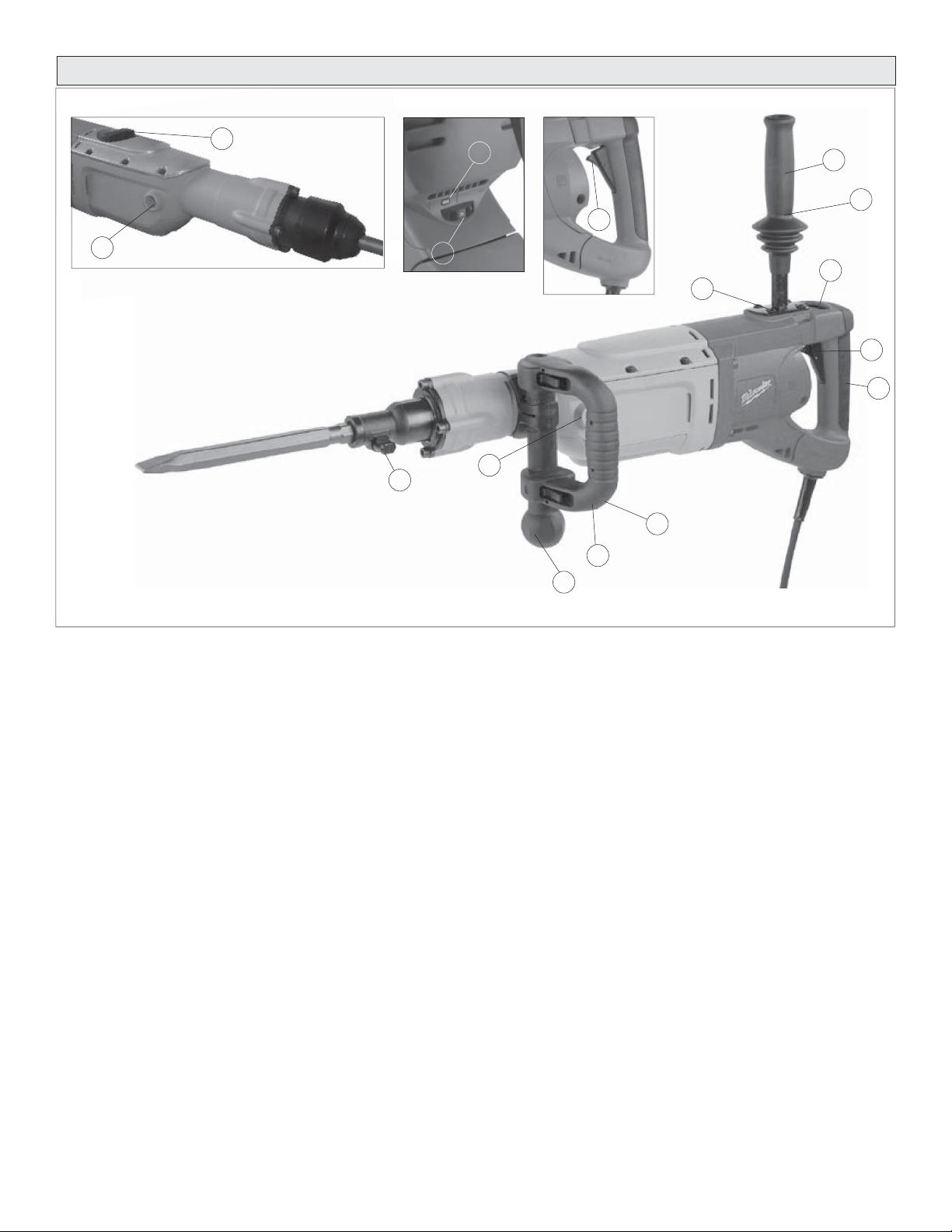
DESCRIPCION FUNCIONAL
12
11
1. Sistema aislador de la vibración
2. Interruptor del gatillo de encendido y apagado
3. Mango de agarre suave
4. Luz indicadora de funcionamiento
5. Indicador de control de la velocidad
6. Botón de traba (Cat. No. 5337-20, 5339-20 únicamente)
7. Mango lateral de la broca (Cat. No. 5337-20, 5339-20 únicamente)
8. Perilla de ajuste del mango lateral de la broca (Cat. No. 5337-20,
5339-20 únicamente)
9. Traba de la broca (Cat. No. 5337-20, 5340-20 únicamente)
10. Mango lateral recto (se debe usar durante el martillado con rotación)
11. Posiciones de montaje del mango lateral recto (3 ubicaciones)
12. Selector de acción (Cat. No. 5339-20, 5342-20 únicamente)
Cat. No. 5342-20
5
9
4
6
11
11
Cat. No. 5337-20
7
1
8
1
10
1
2
3
page 24
Page 25

TIERRA
EXTENSIÓNES ELÉCTRICAS
ADVERTENCIA
Puede haber riesgo de descarga eléctrica si se conecta el cable
de conexión de puesta a tierra incorrectamente. Consulte con un
electricista certifi cado si tiene dudas respecto a la conexión de
puesta a tierra del tomacorriente. No modifi que el enchufe que
se proporciona con la herramienta. Nunca retire la clavija de conexión de puesta a tierra del enchufe. No use la herramienta si el
cable o el enchufe está dañado. Si está dañado antes de usarlo,
llévelo a un centro de servicio MILWAUKEE para que lo reparen. Si
el enchufe no se acopla al tomacorriente, haga que un electricista
certifi cado instale un tomacorriente adecuado.
Herramientas con conexión a tierra:
Herramientas con enchufes de tres clavijas
Las herramientas marcadas con
la frase “Se requiere conexión de
puesta a tierra” tienen un cable de
tres hilo y enchufes de conexión
de puesta a tierra de tres clavijas.
El enchufe debe conectarse a
un tomacorriente debidamente conectado a tierra (véase la Figura A).
Si la herramienta se averiara o no
funcionara correctamente, la con-
exión de puesta a tierra proporciona un trayecto de baja resistencia para
desviar la corriente eléctrica de la trayectoria del usuario, reduciendo de
este modo el riesgo de descarga eléctrica.
La clavija de conexión de puesta a tierra en el enchufe está conectada al
sistema de conexión de puesta a tierra de la herramienta a través del hilo
verde dentro del cable. El hilo verde debe ser el único hilo conectado al
sistema de conexión de puesta a tierra de la herramienta y nunca se debe
unir a una terminal energizada.
Su herramienta debe estar enchufada en un tomacorriente apropiado,
correctamente instalado y conectado a tierra según todos los códigos y
reglamentos. El enchufe y el tomacorriente deben asemejarse a los de la
Figura A.
Herramientas con doble aislamiento:
Herramientas con clavijas de dos patas
Las herramientas marcadas con
“Doble aislamiento” no requieren conectarse “a tierra”. Estas herramientas tienen un sistema aislante que
satisface los estándares de OSHA
y llena los estándares aplicables de
UL (Underwriters Laboratories, Inc.),
de la Asociación Canadiense de Estándares (CSA) y el Código Nacional
de Electricidad. Las herramientas
con doble aislamiento pueden ser
usadas en cualquiera de los toma
corriente de 120 Volt mostrados en
las Figuras B y C.
Fig. A
Fig. B
Fig. C
Las herramientas que deben conectarse a tierra cuentan con clavijas de
tres patas y requieren que las extensiones que se utilicen con ellas sean
también de tres cables. Las herramientas con doble aislamiento y clavijas de
dos patas pueden utilizarse indistintamente con extensiones de dos a tres
cables. El calibre de la extensión depende de la distancia que exista entre
la toma de la corriente y el sitio donde se utilice la herramienta. El uso de
extensiones inadecuadas puede causar serias caídas en el voltaje, resultando en pérdida de potencia y posible daño a la herramienta. La tabla que
aquí se ilustra sirve de guía para la adecuada selección de la extensión.
Mientras menor sea el número del calibre del cable, mayor será la capacidad
del mismo. Por ejemplo, un cable calibre 14 puede transportar una corriente
mayor que un cable calibre 16. Cuando use mas de una extensión para
lograr el largo deseado, asegúrese que cada una tenga al menos, el mínimo
tamaño de cable requerido. Si está usando un cable de extensión para mas
de una herramienta, sume los amperes de las varias placas y use la suma
para determinar el tamaño mínimo del cable de extensión.
Guías para el uso de cables de extensión
• Si está usando un cable de extensión en sitios al aire libre, asegúrese
que está marcado con el sufi jo “W-A” (“W” en Canadá) el cual indica
que puede ser usado al aire libre.
• Asegúrese que su cable de extensión está correctamente cableado
y en buenas condiciones eléctricas. Cambie siempre una extensión
dañada o hágala reparar por una persona califi cada antes de volver a
usarla.
• Proteja su extensión eléctrica de objetos cortantes, calor excesivo o
areas mojadas.
Calibre mínimo recomendado para cables de
Amperios
(En la placa)
5,1 - 8,0
8,1 - 12,0
12,1 - 15,0
15,1 - 20,0
* Basado en limitar la caída en el voltaje a 5 volts
al 150% de los amperios.
extensiónes eléctricas*
Largo de cable de Extensión en (m)
7,6
0 - 5,0
16
16
14
12
10
15,2
16
16
14
12
10
22,8
16
14
12
10
10
30,4
14
12
10
10
--
45,7
12
10
--
--
--
60,9
12
--
--
--
--
LEA Y GUARDE TODAS LAS INSTRUCCIONES
PARA FUTURAS REFERANCIAS.
page 25
Page 26

ENSAMBAJE DE LA HERRAMIENTA
ADVERTENCIA
Para reducir el riesgo de lesiones, desconecte siempre la herramienta antes de fi jar o retirar accesorios, o antes de efectuar
ajustes. Utilice sólo los accesorios específi camente recomenda-
dos. El uso de otros accesorios puede peligroso.
Ajuste del mango lateral de la broca (Cat. No. 5337-20, 5339-20 únicamente)
El mango lateral de la broca se incluye solamente en los martillos de demolición. No use el mango lateral de la broca con martillos rotatorios.
1. Afl oje ligeramente el mango lateral de la broca girando la perilla de
ajuste en sentido antihorario.
2. Gire el mango lateral de la broca hasta llegar a la posición deseada.
El mango se mueve hacia la izquierda o hacia la derecha de la herramienta, así como hacia adelante y hacia atrás.
3. Apriete bien la perilla de ajuste del mango lateral de la broca.
Ajuste del mango lateral recto
Enrosque el mango lateral recto en una de las tres posiciones disponibles:
en la parte superior, al lado izquierdo o al lado derecho. Apriete bien.
ADVERTENCIA
Para reducir el riesgo de lesiones durante el martillado con rotación, use siempre el mango lateral recto con esta herramienta.
Asegure o sujete siempre de forma segura.
Para reducir el riesgo de lesiones durante el martillado con o
sin rotación, use siempre gafas de seguridad con protectores
laterales.
Instalación de brocas y cinceles
1. Limpie y engrase la broca o espiga del cincel.
2. Introduzca la broca o el cincel en el portabrocas de la herramienta.
3. Gire la broca o el cincel lentamente hasta que queden alineados con
el mecanismo de traba.
Espiga SDS max
Cat. No. 5339-20,
5342-20
4. Empuje la broca o el cincel al interior de la herramienta hasta que
queden trabados (Fig. 2).
5. Tire de la broca o del cincel para verifi car que se encuentran trabados
en su posición.
6. Para extraer, tire del collarín de liberación de la broca hacia la parte
trasera de la herramienta y extraiga la broca o el cincel.
ADVERTENCIA
Para reducir el riesgo de lesiones, use únicamente los cinceles
de martillo hechos por MILWAUKEE que se recomiendan es-
pecífi camente. Los de otro tipo podrían ocasionar daños en la
herramienta.
Instalación de los cinceles de martillo
Espiga hexagonal
redonda
(Cat. No. 5340-20)
Espiga hexagonal
(Cat. No. 5337-20)
Espiga estriada
Cat. No. 5340-20
únicamente
Espiga hexagonal
redonda
Cat. No. 5340-20
únicamente
Espiga hexagonal
Cat. No. 5337-20
únicamente
NOTA: Para reducir el riesgo de daños en la traba de la broca, no use las
brocas con espiga hexagonal redonda en el 5337-20. Con esta herramienta
use únicamente brocas con espiga hexagonal.
1. Limpie y engrase la broca o espiga de cincel.
2. Quite la traba de la broca y gírela 180°.
3. Introduzca la broca o el cincel en el portabrocas de la herramienta (Fig. 1).
NOTA: Cuando use brocas o cinceles hexagonales (Cat. No.
5337-20) o hexagonales/redondos (Cat. No. 5340-20), la ranura de la
espiga debe estar orientada hacia la parte inferior del portabrocas de
la herramienta.
Siempre limpie y engrase la espiga antes de introducir el cincel en la herramienta. Inspeccione la espiga y compruebe que no se haya aplastado,
como se describe en “Mantenimiento de los cinceles de martillo”. Asegúrese
siempre de que el cincel esté en buenas condiciones de funcionamiento
antes de usarlo.
page 26
Page 27

OPERACION
Circuito electrónico de control de retroalimentación
Estos martillos tienen un circuito electrónico de control de retroalimentación (EFCC) que ayuda a mejorar el funcionamiento y la duración de la
herramienta.
Control de retroalimentación
El circuito electrónico de control de velocidad permite que la herramienta
mantenga una velocidad y un torque constantes, ya sea con carga o sin
ella.
Arranque suave
La característica de arranque suave reduce el par de la reacción que reciben
la herramienta y el usuario. Esta función permite aumentar gradualmente
la velocidad del motor desde cero hasta la velocidad fi jada mediante el
indicador de control de la velocidad.
ADVERTENCIA
Para reducir el riesgo de lesiones, use siempre lentes de seguridad o anteojos con protectores laterales. Desconecte la herramienta antes de cambiar algún accesorio o de hacerle algún
ajuste.
Selección de la velocidad
El indicador de control de la velocidad de estos martillos permite al usuario
fi jar la velocidad de rotación (RPM) y la frecuencia de impacto (golpes por
minuto) de la herramienta.
Para cambiar la velocidad, coloque el indicador de control de la velocidad
en la posición deseada.
• Las velocidades más bajas proporcionan mayor control al comenzar a
taladrar los agujeros y reduce la exfoliación al comenzar a taladrar. La
exfoliación se produce al comenzar a taladrar, cuando se desprenden
partículas del material que circunda el agujero taladrado. Cuando se
cincele en materiales blandos o quebradizos, use velocidades más
bajas para reducir los daños producidos en las zonas que circundan
al material.
• Las velocidades más altas proporcionan una penetración más rápida
al taladrar o cincelar en obras de demolición.
1. Martillado únicamente. Use esta posición con accesorios de
“martillado únicamente”. Use este ajuste para cincelar.
2. Ajuste del cincel. Use esta posición para ajustar el ángulo de la
hoja del cincel con respecto a la herramienta. Con el cincel montado en
la herramienta, gire el cincel hasta conseguir el ángulo deseado. Para
iniciar entonces la operación, gire el selector de acción colocándolo
en la posición de “martillado únicamente”.
NOTA: Para activar el mecanismo de martillado, mantenga la presión sobre
la broca/cincel. Al liberar la presión, el martillado se detiene.
Cat. No. 5340-20
El martillo rotatorio Cat. No. 5340-20 dispone de “martillado únicamente”
y “martillado con rotación”, dependiendo del tipo de espiga que se haya
introducido en la herramienta.
Para “martillado únicamente”: Introduzca un cincel u otro accesorio de
“martillado únicamente” con una espiga hexagonal de 3/4" con cabeza
redonda de 21/32" en el portabrocas de la herramienta (consulte
“Introducción de brocas y cinceles”). El mecanismo impulsor de rotación
funcionará pero no se engranará con el cincel, obteniéndose la acción de
“martillado únicamente”.
Para “martillado con rotación”: Introduzca una broca o una broca sacabo-
cados con una espiga estriada en el portabrocas de la herramienta
(consulte “Introducción de brocas y cinceles”). El mecanismo impulsor de
rotación se engrana con la broca, obteniéndose la acción de “martillado
con rotación”.
Cat. No. 5342-20 (Fig. 4)
El martillo rotatorio Cat. No. 5342-20 incluye los ajustes de “martillado
únicamente”, “martillado con rotación” y “ajuste del cincel”. El selector de
acción se usa precisamente para seleccionar la acción:
Fig. 4
Martillado
únicamente
Ajuste del cincel
Martillado con
rotación
Selección de acción
Cat. No. 5337-20
El martillo perforador de demolición Cat. No. 5337-20 se usa para “martillado
únicamente”. No dispone de rotación. Solamente se deben usar cinceles y
demás accesorios de “martillado únicamente”.
Cat. No. 5339-20 (Fig. 3)
El martillo perforador de demolición Cat. No. 5339-20 se usa para “martillado únicamente”. No dispone de rotación. El selector de acción se usa
precisamente para seleccionar la acción:
Fig. 3
Martillado
únicamente
Ajuste del cincel
1. Martillado únicamente. Use esta posición con accesorios de
“martillado únicamente”. Use este ajuste para cincelar.
2. Martillado con rotación. Use este ajuste para taladrar agujeros
con brocas. No use “martillado con rotación” con cinceles u otros accesorios de “martillado únicamente”.
3. Ajuste del cincel. Use esta posición para ajustar el ángulo de la
hoja del cincel con respecto a la herramienta. Con el cincel montado en
la herramienta, gire el cincel hasta conseguir el ángulo deseado. Para
iniciar entonces la operación, gire el selector de acción colocándolo
en la posición de “martillado únicamente”.
NOTA: Para activar el mecanismo de martillado, mantenga la presión sobre
la broca/cincel. Al liberar la presión, el martillado se detiene.
ADVERTENCIA
Para reducir el riesgo de lesiones, cuando se usen cinceles u
otros accesorios de “martillado únicamente” en el modelo Cat.
No. 5342-20, el selector de acción se debe fi jar en la posición de
“martillado únicamente”.
page 27
Page 28

Arranque y parada de la herramienta
1. Para arrancar la herramienta, pulse el gatillo.
2. Para parar la herramienta, suelte el gatillo.
Traba del gatillo (Cat. No. 5337-20, 5339-20 únicamente)
El botón de traba de los martillos perforadores de demolición mantiene el
gatillo en la posición de “encendido” para uso continuado.
1. Para trabar el gatillo, mantenga pulsado el botón de traba mientras se
pulsa el gatillo. Suelte el gatillo.
2. Para destrabar el gatillo, púlselo y, a continuación, suéltelo.
El botón de traba saltará.
Martillado en frío
Si el martillo ha estado almacenado durante un largo periodo de tiempo
a bajas temperaturas, es posible que el lubricante se haya endurecido y
que la herramienta no martillee inicialmente o que el martillado sea débil.
Si esto ocurriera:
1. Introduzca el cincel en la herramienta.
2. Pulse el gatillo y haga funcionar el cincel sobre un pedazo de
concreto.
3. Encienda y apague la herramienta varias veces a intervalos de
varios segundos. Al cabo de un periodo de entre 15 segundos y
2 minutos, la herramienta comenzará a martillar con normalidad. Cuanto
más frío esté el martillo, más tiempo tardará en calentarse.
Fuerza requerida del operador
Estos martillos cuentan con el sistema aislador de vibración que proporciona
confort al operador sin sacrifi car potencia o rendimiento. El alojamiento del
motor se encuentra suspendido independientemente del mango del interruptor. Los elementos aislantes absorben la vibración durante el martillado
y el taladro.
Fuerza ideal del operador: el mango se presiona ligeramente y permite que
la herramienta funcione vigorosamente mientras que el mango proporciona
una amortiguación máxima de la vibración.
Fuerza excesiva del operador: el mango se presiona demasiado reduciendo así la amortiguación de la vibración. Los usuarios podrán sentir
la diferencia y deberán ajustar adecuadamente la fuerza con la que se
presiona el mango.
ADVERTENCIA
Al aplicar demasiada presión no se incrementa la efi cacia de
la herramienta. Si la presión de funcionamiento aplicada es
demasiado alta, el amortiguador se comprime haciendo que las
vibraciones del mango sean perceptiblemente más fuertes.
Martillado únicamente
1. Introduzca un cincel u otro accesorio de “martillado únicamente” en la
herramienta (consulte “Instalación de brocas y cinceles”).
2. Coloque la herramienta en la pieza de trabajo.
3. Sujete ambos mangos con fi rmeza (el mango del gatillo y el mango de
la broca o el mango lateral).
4. Pulse el gatillo. Sujete siempre la herramienta de manera segura usando
los dos mangos y mantenga el control.
5. Use únicamente la presión necesaria para mantener la herramienta en
su lugar, para activar el mecanismo de martillado y para evitar que la
punta del cincel se desplace. Esta herramienta se ha diseñado para
obtener una efi cacia máxima a presión moderada. Deje que la her-
ramienta realice el trabajo.
NOTA: Para activar el mecanismo de martillado, mantenga la presión
sobre la broca/cincel. Al liberar la presión, el martillado se detiene.
6. Cuando se cincele o se corte, mantenga la herramienta en ángulo
con respecto a la zona de trabajo. Para obtener una máxima efi cacia,
empiece a trabajar desde una esquina o cerca del borde de la zona
de trabajo y vaya cortando pequeñas áreas cada vez.
Si un accesorio de martillo queda atascado:
1. Desenchufe la herramienta.
2. Quite la traba de la broca y gírela 180°.
3. Extraiga la herramienta del accesorio atascado.
4. Extraiga el accesorio de la pieza de trabajo.
Hammering with Rotation
1. Introduzca una broca o broca sacabocados en la herramienta (consulte
“Instalación de brocas y cinceles”).
2. Coloque la herramienta en la pieza de trabajo.
3. Sujete ambos mangos con fi rmeza (el mango del gatillo y el mango
lateral).
ADVERTENCIA
Para reducir el riesgo de lesiones, asegure o sujete de forma
segura. Esté preparado ante una posible reacción del taladro,
cuando la broca se trabe, cuando el agujero se tapone, cuando
se golpeen materiales incrustados y al comenzar a perforar un
agujero.
4. Pulse el gatillo. Sostenga siempre la herramienta de forma segura utilizando el mango recto y el mango del gatillo y mantenga el control.
5. Use únicamente la presión necesaria para mantener la herramienta en
su lugar, activar el mecanismo de martillado y evitar que la punta de la
broca se desplace. Esta herramienta se ha diseñado para obtener una
efi cacia máxima a presión moderada. Deje que la herramienta realice
el trabajo.
Al liberar la presión, el martillado se detiene.
6. Es posible que la velocidad diminuya al taladrar agujeros profundos.
Con el fi n de eliminar algo de polvo, extraiga parte de la broca del
agujero mientras que la herramienta sigue funcionando.
NOTA: No use agua para asentar el polvo, ya que se obturarán las
estrías de la broca y harán que la broca se atasque en el agujero.
page 28
Si una broca se atasca:
Si la broca se atasca, el embrague de deslizamiento integrado no ajustable
evita que la broca gire cuando la herramienta se sujeta o se afi anza de
manera segura. Si esto ocurriera:
1. Apague y desenchufe la herramienta.
2. Extraiga la broca de la pieza de trabajo.
3. Limpie los residuos del agujero.
4. Comience a taladrar nuevamente.
Page 29

ADVERTENCIA
Utilice las brocas sacamuestras MILWAUKEE no de cat.
48-20-5125 a 48-20-5165. No use los componentes LHS (sistema
de agujero grande) con los martillos rotatorios 5340-20 y 5342-
20. Las brocas pueden fallar, quebrarse por el vástago roscado y
causar lesiones y daños a la propiedad.
Uso de las brocas sacabocados de percusión rotatorias (Fig. 5 - 7)
Las brocas sacabocados son útiles para taladrar agujeros más grandes en
canalizaciones y tuberías. Las brocas sacabocados Heavy-Duty de MIL-
WAUKEE constan de cuerpos de acero tratados térmicamente con puntas
de carburo de larga duración. Estas brocas sacabocados se han diseñado
especialmente para efectuar un taladro rápido y preciso combinado con el
martillado y la acción rotatoria.
1. Limpie y engrase las roscas del adaptador y de la broca sacabocados
para facilitar su posterior extracción. Enrosque el extremo roscado del
adaptador en la parte posterior de la broca sacabocados.
2. Empuje la placa de la guía sobre el extremo en punta del pasador
central. Introduzca el conjunto del pasador central y la placa de la guía
en la broca sacabocados. Asegúrese de que el extremo pequeño del
pasador central se haya sujetado de forma segura en el orifi cio de la
parte central de la broca sacabocados (Fig. 5).
Fig. 5
3. Introduzca el adaptador en el portabrocas de la herramienta (consulte
“Instalación de brocas y cinceles”). Coloque el selector de acción en
el ajuste de martillado con rotación.
4. Presione el pasador central con fi rmeza sobre la marca central; sujete
la herramienta con fuerza y pulse el gatillo (Fig. 6).
Fig. 6
NOTA: Si no se dispone de pasador central o de placa de la guía,
use una plantilla o un tablero muescado para iniciar el agujero
(Fig. 7).
Fig. 7
5. Después de taladrar un agujero con una profundidad aproximadamente
igual al diente de la broca sacabocados, extraiga el pasador central y
la placa de la guía de la broca sacabocados. Reanude el taladro.
6. Para cambiar la broca sacabocados, coloque la herramienta hacia
arriba, apuntando en dirección contraria al cuerpo del operador y
póngala en funcionamiento permitiendo que gire e impacte durante
cinco segundos para afl ojar la broca sacabocados de la espiga del
adaptador.
NOTA: Para efectuar agujeros más profundos, extraiga la broca
sacabocados para fragmentar y extraer el bocado. Reanude el taladro.
Cuando taladre agujeros largos o profundos, tras cada par de centímetro
taladrados extraiga parcialmente la broca del agujero mientras que la
herramienta sigue funcionando para así eliminar el polvo de las estrías
de la broca. El polvo puede obturar las estrías de la broca y atascarla
en el agujero. Si esto ocurriera, pare la herramienta, desatasque la
broca y comience de nuevo.
Perforación de agujeros de gran diámetro con brocas sacabocados
(Fig. 8-13)
Cuando se perforen agujeros con brocas sacabocados de gran diámetro,
el polvo se puede acumular en el corte y hacer que la herramienta se pare,
se atasque o corte lentamente. Al crearse una abertura para que salga el
polvo se puede reducir el tiempo de perforación y el esfuerzo de la herramienta y broca.
1. Comience a cortar normalmente.
2. Una vez que la broca esté bien asentada en el corte (aproximadamente
a 6,4 mm(1/4 pulg.) de profundidad), saque la broca del corte (Fig. 8).
3. Extraiga la broca de la herramienta.
Fig. 8
Taladre a una profun-
didad aproximada de
6,4 mm (1/4") con una
broca sacabocados.
4. Instale en la herramienta una broca con estrías normales, de aproximadamente 22,2 mm(7/8 de pulg.) de diámetro.
5. Taladre un perpendicular agujero a través de la entalladura del agujero
grande (Fig. 9).
page 29
Page 30

• Dependiendo de la ubicación de la tarea, el agujero debe atravesar al
otro lado del agujero/base o extenderse de 101,6 mm a 127,0 mm (4 a 5
pulgadas) más allá del extremo de la pieza en dónde se trabaja (como,
por ejemplo, en la tierra por debajo de una plancha de concreto).
• Si el polvo se acumula en el agujero, aspírelo y siga taladrando.
• Si se está taladrando en una pared, el agujero para el polvo se debe
perforar en la parte más baja de la entalladura del agujero grande (Fig.
9) ya que el polvo caerá allí cuando se taladra y se puede extraer más
fácilmente.
Fig. 9
Perfore un agujero
a través del sitio en
dónde se trabaja.
6. Vuelva a instalar la broca sacabocados y siga taladrando (Fig. 10 y
11). El polvo y los desechos caerán a través del agujero y mejorarán
la capacidad de corte de la broca.
Fig. 10
• Saque el bocado y aspire/retire el polvo y los desechos restantes.
• Instale la broca sacabocados y continúe con el corte.
Fig.
NOTA: Si no se puede taladrar un agujero en la entalladora, retire la broca
con el martillo en marcha (Fig. 13). Esto eliminará algo de polvo y desechos
del corte. Repita este procedimiento por cada pulgada que perfore. Si es
necesario, aspire el polvo y los residuos del corte y el área circundante.
Saque la broca tanto
Fig. 13
como sea posible un
o dos veces por cada
pulgada taladrada.
El polvo y los
desechos caerán
a través del agu-
jero.
Vista superior
Fig. 11
Vista lateral de la plancha
7. Para las brocas sacabocados, una vez que se haya taladrado la profundidad máxima del bocado, Éste debe fragmentarse y extraerse.
• Instale una broca de cincel.
• Coloque el cincel en la entalladura del agujero (Fig. 12).
• Cincele hacia abajo, en varios puntos de la entalladura, hasta que la
muestra se suelte o se rompa.
Cincelado y corte
Los Martillos de MILWAUKEE pueden utilizarse para trabajos livianos de
corte y cincelado.
Cuando cincele, mantenga la herramienta a un ángulo con la pieza de
trabajo. Trabaje desde una esquina o cerca del borde del área de trabajo,
rompiendo poco a poco, más que intentando romper un área demasiado
grande.
Hay una variedad de accesorios disponibles.
Martelinas
Para superfi cies de concreto
Cinceles para cortar mortero
Para la remoción de mortero viejo o retoques
Cinceles con punta
Para trabajos de demolición e inicio de perforación en losas de concreto
Cinceles en plano
Para orillar, eliminar rebabas o para acanalar.
Cinceles desincrustadores
Para la remoción de salpicaduras de soldadura
o corte de líneas rectas
page 30
Cinceles de ranurado
Para acanalar o cortar entre agujeros perforados
en concreto y mampostería.
Page 31

MANTENIMIENTO
ACCESORIOS
ADVERTENCIA
Para reducir el riesgo de lesiones, desconecte siempre la herramienta antes de darle cualquier mantenimiento. Nunca desarme
la herramienta ni trate de hacer modifi caciones en el sistema
eléctrico de la misma. Acuda siempre a un Centro de Servicio
MILWAUKEE para TODAS las reparaciones.
Mantenimiento de las herramientas
Adopte un programa regular de mantenimiento y mantenga su herramienta
en buenas condiciones. Antes de usarla, examine las condiciones generales
de la misma. Inspeccione guardas, interruptores, el cable de la herramienta
y el cable de extensión. Busque tornillos sueltos o fl ojos, defectos de
alineación y dobleces en partes móviles, así como montajes inadecuados,
partes rotas y cualquier otra condición que pueda afectar una operación
segura. Si detecta ruidos o vibraciones anormales, apague la herramienta
de inmediato y corrija el problema antes de volver a usarla. No utilice una
herramienta dañada. Colóquele una etiqueta que diga “NO DEBE USARSE”
hasta que sea reparada (vea “Reparaciones”).
Bajo condiciones normales, no se requiere lubricación hasta que haya que
cambiar los carbones. Después de 6 meses a un año, dependiendo del
uso dado, envíe su herramienta al Centro de Servicio MILWAUKEE más
cercano para que le hagan:
• Lubricación
• Inspección y cambio de carbones
• Inspección mecánica y limpieza (engranes, fl echas, baleros,
carcarza, etc.)
• Inspección eléctrica (interruptor, cable, armadura, etc.)
• Probarla para asegurar una operación mecánica y eléctrica
adecuada.
Mantenimiento de las brocas de martilleo
Inspeccione la punta de la varilla para asegurarse que no esté embotada.
Luego extraiga la broca o el cincel. Vea que la broca de martilleo esté en
buen estado.
Cómo reemplazar las escobillas
La herramienta no funciona cuando las escobillas están desgastadas.
Envíe su herramienta al Centro de Servicio MILWAUKEE más cercano
para que le hagan.
Luz indicadora de servicio
Estos martillos están equipados con una luz indicadora de servicio. Cuando
la luz roja de servicio se enciende, se debe realizar el servicio de la herramienta. Devuelva la herramienta a cualquiera de los centros de servicio
autorizado.
NOTA: Cuando se enciende la luz de servicio, la herramienta continuará
funcionando por algunas horas y luego el motor se apagará.
ADVERTENCIA
Para reducir el riesgo de lesiones, descarga eléctrica o daño a la
herramienta, nunca la sumerja en líquidos ni permita que estos
fl uyan dentro de la misma.
Limpieza
Limpie el polvo y suciedad de las ventilas. Mantenga las empuñaduras de la
herramienta limpias, secas y libres de aceite y grasa. Use sólo jabón neutro
y un trapo húmedo para limpiar su herramienta ya que algunas substancias
y disolventes limpiadores pueden ocasionar daños a materiales plásticos
y partes aislantes. Algunos de estos incluyen: gasolina, trementina, diluyente para barniz, diluyente para pintura, disolventes limpiadores clorados,
amoníaco, y detergentes caseros que contengan amoníaco.
Reparaciones
Si su instrumento se daña, vuelva el instrumento entero al más cercano
centro de reparaciones.
ADVERTENCIA
Para reducir el riesgo de lesiones, desconecté siempre su
herramienta antes de colocar o retirar un accesorio. Use solo
accesorios recomendados específi camente. Otros puenden
peligrosos.
Para una lista completa de accessorios, refi érase a su catálogo MILWAUKEE
Electric T ool o visite nuestro sitio en Internet: www .milwaukeetool.com. Para
obtener un catálogo, contacte su distribuidor local o uno de los centros.
Brocas sacamuestras con puntas de carburo para paredes gruesas
Cuerpo de la broca con placa guía y pasador de centrado
Diámetro Profundidad de perforación Cat. No.
38,1 mm 103,2 mm 48-20-5125
44,5 mm 103,2 mm 48-20-5130
50,8 mm 103,2 mm 48-20-5135
63,5 mm 103,2 mm 48-20-5140
76,2 mm 103,2 mm 48-20-5145
88,9 mm 103,2 mm 48-20-5150
101,6 mm 103,2 mm 48-20-5155
127,0 mm 103,2 mm 48-20-5160
152,4 mm 103,2 mm 48-20-5165
NOTA: Utilice las brocas sacamuestras MILWAUKEE cat. no. 48-20-5125 a
48-20-5165. No use los componentes LHS (sistema de agujero grande) con
los martillos rotatorios 5340-20 y 5342-20. Las brocas pueden fallar, quebrarse por el vástago roscado y causar lesiones y daños a la propiedad.
GARANTÍA LIMITADA DE CINCO AÑOS
Todas las herramientas MILWAUKEE se prueban antes de abandonar la
fábrica y se garantiza que no presentan defectos ni en el material ni de
mano de obra. En el plazo de cinco (5) años a partir de la fecha de compra
MILWAUKEE reparará o reemplazará (a discreción de MILWAUKEE), sin
cargo alguno, cualquier herramienta (cargadores de baterías inclusive) cuyo
examen determine que presenta defectos de material o de mano de obra.
Devuelva la herramienta, con gastos de envío prepagados y asegurada, y
una copia de la factura de compra, u otro tipo de comprobante de compra,
a una sucursal de reparaciones/ventas de la fábrica MILWAUKEE o a un
centro de reparaciones autorizado por MILW AUKEE. Esta garantía no cubre
los daños ocasionados por reparaciones o intentos de reparación por parte
de personal no autorizado por MILWAUKEE, abuso, desgaste y deterioro
normal, falta de mantenimiento o accidentes.
El período de garantía para las baterías V28 es de dos (2) años a partir de la
fecha de compra. El período de garantía para las baterías Ni-Cd, linternas,
radios y polipastos es de un (1) año a partir de la fecha de compra.
LOS DERECHOS A REPARACIÓN Y REEMPLAZO DESCRITOS EN
EL PRESENTE DOCUMENTO SON EXCLUSIVOS. MILWAUKEE NO
SERÁ EN NINGÚN CASO RESPONSABLE DE DAÑOS INCIDENTALES,
ESPECIALES O CONSECUENTES, INCLUYENDO LA PÉRDIDA DE
GANANCIAS.
ESTA GARANTÍA ES EXCLUSIVA Y SUSTITUYE A TODA OTRA GARANTÍA, O CONDICIONES, ESCRITAS U ORALES, EXPRESAS O
IMPLÍCITAS DE COMERCIALIZACIÓN O IDONEIDAD PARA UN USO O
FIN DETERMINADO.
Esta garantía le proporciona derechos legales específi cos. Es posible que
usted tenga otros derechos que varían de estado a estado y de provincia
a provincia. En aquellos estados que no permiten la exclusión de garantías
implícitas o la limitación de daños incidentales o consecuentes, las limitaciones anteriores pueden que no apliquen. Esta garantía es válida solamente
en los Estados Unidos, Canadá y México.
page 31
Page 32

UNITED STATES
CANADA
MILWAUKEE Service
MILWAUKEE prides itself in producing a
premium quality product that is
NOTHING BUT HEAVY DUTY®.
Your satisfaction with our products is
very important to us!
If you encounter any problems with the
operation of this tool, or you would like to
locate the factory Service/Sales Support Branch
or authorized service station nearest you,
please call...
1-800-SAWDUST
(1.800.729.3878)
NATIONWIDE TOLL FREE
Monday-Friday • 8:00 AM - 4:30 PM • Central Time
or visit our website at
www.milwaukeetool.com
For service information, use the 'Service Center
Search' icon found in the 'Parts & Service' section.
Service MILWAUKEE
MILWAUKEE est fi er de proposer un produit de
première qualité N
satisfaction est ce qui compte le plus!
En cas de problèmes d’utilisation de l’outil ou
pour localiser le centre de service/ventes ou le
centre d’entretien le plus proche, appelez le...
OTHING BUT HEAVY DUTY
®
. Votre
416.439.4181
fax: 416.439.6210
Milwaukee Electric Tool (Canada) Ltd
755 Progress Avenue
Scarborough, Ontario M1H 2W7
Notre réseau national de distributeurs agréés se
tient à votre disposition pour fournir l’aide technique,
l’outillage et les accessoires nécessaires. Composez
le 416.439.4181 pour obtenir les noms et adresses
des revendeurs les plus proches ou bien consultez
la section «Où acheter» sur notre site web à l’adresse
www.milwaukeetool.com
Additionally, we have a nationwide network of
authorized Distributors ready to assist you with your
tool and accessory needs. Check your “Yellow Pages”
phone directory under “Tools-Electric” for the names
& addresses of those nearest you or see the
'Where To Buy' section of our website.
Corporate After Sales Service - Technical Support
Brookfi eld, Wisconsin USA
•Technical Questions •Service/Repair Questions •Warranty
1-800-SAWDUST
(1.800.729.3878)
fax:1.800.638.9582
email: metproductsupport@milwaukeetool.com
Monday-Friday • 8:00 AM - 4:30 PM • Central Time
MEXICO
Soporte de Servicio MILWAUKEE
Milwaukee Electric Tool, S.A. de C.V.
Blvd. Abraham Lincoln no. 13
Colonia Los Reyes Zona Industrial
Tlalnepantla, Edo. México C.P. 54073
Tel. (55) 5565-1414 Fax: (55) 5565-6874
Adicionalmente, tenemos una red nacional de
distribuidores autorizados listos para ayudarle con
su herramienta y sus accesorios. Por favor, llame
al (55) 5565-1414 para obtener los nombres y
direcciones de los más cercanos a usted, o consulte
la sección ‘Where to buy’ (Dónde comprar) de
nuestro sitio web en
www.milwaukeetool.com
MILWAUKEE ELECTRIC TOOL CORPORATION
13135 West Lisbon Road • Brookfi eld, Wisconsin, U.S.A. 53005
58-14-5337d5 10/05 Printed in Germany
 Loading...