

Milwaukee RAVL42 User Manual
P/N 775,219M REV. D 03/2010
TM
US
Portland
OTL Report No. 050-S-08c-5
Ce manuel d’installation est disponible en francais, simplement en faire la
demande. Numéro de la pièce 775,219CF.
INSTALLATION AND OPERATION
Direct-Vent
RAVELLE™ 42
MODEL
RAVL42
WARNING
HOT GLASS WILL
CAUSE BURNS.
DO NOT TOUCH GLASS
UNTIL COOLED.
NEVER ALLOW CHILDREN TO
TOUCH GLASS.
This appliance may be installed in an aftermarket permanently located, manufactured home (USA only) or mobile
home, where not prohibited by local codes. This appliance is only for use with the type of gas indicated on the rating
plate. This appliance is not convertible for use with other gases, unless a certified kit is used.
WARNING: If the information in these instructions is
not followed exactly, a fire or explosion may result
causing property damage, personal injury or death.
- Do not store or use gasoline or other flammable vapors and
liquids in the vicinity of this or any other appliance.
- WHAT TO DO IF YOU SMELL GAS
• Do not try to light any appliance.
• Do not touch any electrical switch; do not use any
phone in your building.
• Immediately call your gas supplier from a neighbor’s
phone. Follow the gas supplier’s instructions.
• If you cannot reach your gas supplier, call the fire
department.
- Installation and service must be performed by a quali
fied installer, service agency or the gas supplier.
INSTALLER: Leave this manual with the appliance.
CONSUMER: Retain this manual for future reference.
AVERTISSEMENT
UNE SURFACE VITRÉE CHAUDE PEUT
CAUSER DES BRÛLURES.
LAISSER REFROIDIR LA SURFACE
VITRÉE AVANT D'Y TOUCHER.
NE PERMETTEZ JAMAIS À UN ENFANT
DE TOUCHER LA SURFACE VITRÉE.
AVERTISSEMENT: Assurez-vous de bien suivre les
instructions données dans cette notice pour réduire
au minimum le risque d’incindie ou d’explosion ou
pour éviter tout dommage matériel, toute blessure
ou la mort.
- Ne pas entreposer ni utilizer d’essence ni d’autres
vapeurs ou liquides inflammables dans le voisinage
de cet appareil ou de tout autre appareil.
- QUE FAIRE SI VOUS SENTEZ UNE ODEUR DE GAZ:
• Ne pas tenter d’allumer d’appareil.
• Ne touchez à aucan interrupteur. Ne pas vous servir
des téléphones se trouvant dans le bâtiment où vous
-
trouvez.
• Appelez immédiatement votre fournisseur de gaz
depuis un voisin. Suivez les instructions du fournisseur.
• Si vous ne pouvez rejoindre le fournisseur de gaz,
appelez le service des incindies.
INSTALLATEUR: Laissez cette notice avec l'appareil.
CONSOMMATEUR
tation ultérieure.
: Conservez cette notice pour consul-
- L’installation et l’entretien doivent être assurés par un
installateur ou un service d’entretien qualifié ou par
le fournisseur de gaz.

CONGRATULATIONS!
When you purchased your new gas fireplace, you joined the
ranks of thousands of individuals whose answer to their home
heating needs reflects their concern for aesthetics, efficiency
and our environment. We extend our continued support to help
you achieve the maximum benefit and enjoyment available from
your new gas fireplace.
Thank you for selecting a Lennox Hearth Products gas fireplace
as the answer to your home heating needs.
TABLE OF CONTENTS
Using this Manual ...................................................... 2
Safety and Warning Information ....................................... 3
Orifice Size/Altitude Adjustment .......................................... 4
Smoke Detectors ............................................................ 4
Ravelle™ 42 Fireplace ..................................................... 4
Codes and Approvals ....................................................... 4
Commonwealth of Massachusetts Requirements ...................... 4
New York City, New York (MEA) .......................................... 4
Pre-Installation............................................................6-7
Features ............................................................
Venting ..............................................................
Fuel
Specifications ......................................................
Packaging List .....................................................
Preparing your Fireplace for Installation .........................
Clearances to Combustibles .....................................
Installation ............................................................... 8-13
Framing Dimensions .............................................
Fireplace Dimensions ............................................
Raised Installations .............................................
Hearth Extension Considerations ..............................
Facing Installation Considerations ............................
Face Installation .................................................
Vent Installation ....................................................... 14-28
Application ........................................................
Vent Parts List ....................................................
Vent Considerations .............................................
Horizontal Vent Installation .....................................
Vertical Vent Installation ........................................
Flue Restrictors ..................................................
.................................................................. 6
6
6
6
6
7
7
8
9
10
10
11
13
14
14
16
17
17
18
Vertical Vent Termination Clearances ........................ 18
Horizontal Terminations .........................................
Vertical Terminations ............................................
Horizontal Vent Termination Clearances .....................
Brick Panel and Log Set Installation .................................... 21
Electrical Connections ....................................................22
Blower Removal ........................................................... 22
Gas Line Installation ......................................................23
Gas Pressure Requirements ....................................
LP and Natural Gas Supplies ...................................
Increasing Efficiency And Hot Air Movement ..........................24
Forced Air Heating Installation ......................................25-28
Attaching Safety In Operation Warnings ............................... 29
Operating Instructions ................................................ 30-33
Pre-Lighting Checklist ...........................................
Lighting Instructions .............................................
Flame Color and Behavior ......................................
Air Shutter Adjustment ..........................................
Paint Curing .......................................................
Quiet Operation ...................................................
Blower Operation .................................................
Optional Wall Thermostat .......................................
Operating Options ................................................
Millivolt Control System ........................................
Maintenance and Servicing ..........................................34-35
Maintenance Checklist ..........................................
Vent Pipe Maintenance ..........................................
Opening and Removing Door ...................................
Glass/Door Maintenance ........................................
Fuel Conversion ..................................................
Troubleshooting ............................................................ 36
Replacement Parts ........................................................37
Accessories .............................................................37-38
Fireplace Labels .......................................................39-40
Product Reference Information .......................................... 42
19
19
20
23
23
30
30
31
32
32
32
32
32
33
33
34
34
35
35
35
USING THIS MANUAL
Please read and carefully follow all of the instructions found in this
manual. Please pay special attention to the safety instructions provided
in this manual.
PRODUCT IS SUBJECT TO CHANGE WITHOUT NOTICE
2
IMPORTANT SAFETY AND WARNING
INFORMATION
WARNING
Young children should be carefully supervised when
they are in the same room as the appliance. Toddlers, young children and others may be susceptible
to accidental contact burns. A physical barrier is
recommended if there are at risk individuals in the
house. To restrict access to a fireplace or stove,
install an adjustable safety gate to keep toddlers,
young children and other at risk individuals out of
the room and away from hot surfaces.
AVERTISSEMENT
On ne devrait pas placer de vêtements ni d’autres
matières inflammables sur l’appareil ni à proximité.
WARNING
Any safety screen or guard removed for servicing
the appliance must be replaced prior to operating
the appliance.
AVERTISSEMENT
AVERTISSEMENT
Les jeunes enfants devraient être surveillés étroitement lorsqu’ils se trouvent dans la même pièce que
l’appareil. Les tout petits, les jeunes enfants ou les
adultes peuvent subir des brûlures s’ils viennent en
contact avec la surface chaude. Il est recommandé
d’installer une barrière physique si des personnes à
risques habitent la maison. Pour empêcher l’accès
à un foyer ou à un poêle, installez une barrière de
sécurité; cette mesure empêchera les tout petits,
les jeunes enfants et toute autre personne à risque
d’avoir accès à la pièce et aux surfaces chaudes.
WARNING
Improper installation, adjustment, alteration, service or maintenance can cause injury or property
damage. Refer to this manual. For assistance or
additional information consult a qualified installer,
service agency or the gas supplier.
WARNING
Failure to comply with these installation instructions
will result in an improperly installed and operating
appliance, voiding its warranty. Any change to this
appliance and/or its operating controls is dangerous.
WARNING
Clothing or other flammable material should not
be placed on or near the appliance.
Tout écran ou protecteur retiré pour permettre
l’entretien de l’appareil doit être remis en place
avant de mettre l’appareil en marche.
WARNING
Improper installation or use of this appliance can
cause serious injury or death from fire, burns,
explosion or carbon monoxide poisoning.
WARNING
Children and adults should be alerted to the hazards
of high surface temperature and should stay away to
avoid burns or clothing ignition.
AVERTISSEMENT
Les enfants et les adultes devraient être infor-més
des dangers que posent les températures de surface
élevées et se tenir à distance afin d’éviter des brûlures
ou que leurs vêtements ne s’enflamment.
WARNING
DO NOT ATTEMPT TO ALTER OR MODIFY THE CONSTRUCTION OF THE APPLIANCE OR ITS COMPONENTS. ANY MODIFICATION OR ALTERATION MAY
VOID THE WARRANTY, CERTIFICATION AND LISTINGS
OF THIS UNIT.
3

FOR YOUR SAFETY do not install or operate this appliance without
first reading and understanding this manual. Any installation or
operation of the appliance deviating from that which is stated
in this manual WILL void the warranty and may be hazardous.
INSTALLATION AND REPAIR SHOULD ONLY BE DONE BY
A QUALIFIED SERVICE TECHNICIAN. DO NOT ATTEMPT
TO SERVICE THE APPLIANCE YOURSELF.
Do not make any make-shift compromises during installation.
Any modification or alteration may result in damage to the appliance or dwelling and will void the warranty, certification and
listings of this unit.
Failure to use manufacturer provided parts, variations in tech-
niques and construction materials or practices other than those
described in this manual may create a fire hazard and void the
limited warranty.
This gas appliance must be equipped for the proper fuel type
and altitude at which it will be operated. Any operation outside
the parameters outlined in this manual may result in a hazardous condition and will void the warranty. Please carefully read
the sections pertaining to these subjects and/or be sure your
appliance is properly equipped.
Never use solid fuels such as wood, paper, cardboard, coal, or
any flammable liquids, etc., in this appliance.
Any grill, panel, or glass removed for service MUST be replaced
prior to operating the appliance. Do not operate appliance with
the glass front removed, cracked or broken.
These appliances are vented gas appliances. Do not burn wood
or other material in these appliances.
This appliance is only for use with the type of gas indicated on
rating plate. This appliance is not convertible for use with other
gases, unless a certified kit is used.
Cet appareil doit être utilisé uniquement avec les types de gaz
indiqués sur la plaque signalétique. Ne pas l'utiliser avec
d'autres gaz sauf si un kit de conversion certifié est installé.
Hot while in operation. Do not touch. Severe Burns may result.
Keep children, clothing furniture, gasoline and other liquids
having flammable vapors away.
L’appareil est chaud lorsqu’il fonctionne. Ne pas toucher
l’appareil. Risque de brûlures graves. Surveiller les enfants.
Garder les vêtements, les meubles, l’essence ou autres liquides
produisant des vapeur inflammables loin de l’appareil.
This appliance may be installed in an aftermarket, permanently
located, manufactured home (USA only) or mobile home, where
not prohibited by local codes.
Cet appareil peut être installé dans une maison préfabriquée
(mobile) déjà installée à demeure si les règlements locaux le
permettent.
Ensure clearances are in accordance with local installation
codes and the requirements of the gas supplier.
Dégagement conforme aux codes d'installation locaux et aux
exigences du foumisseunde gaz.
Gold and nickel plated surfaces must be cleaned with glass
cleaner and a clean soft cloth before firing the first time or
fingerprints will remain permanently. NEVER use brass polish
to clean gold or nickel, this will remove the plating!!!
When opening the lower door on the face while the appliance is
burning, pull at the far left or far right vent openings, because
the door is hot during operation.
LHP, its employees, or any of its representatives assume no
responsibility for any damages caused by an inoperable, inadequate, or unsafe condition as a result of any improper operation,
service or installation procedures, whether direct or indirect.
Due to high temperatures, the appliance should be located out
of traffic and away from furniture and draperies.
En raison des températures élevées, l’appareil devrait être
installé dans un endroit où il y a peu de circulation et loin du
mobilier et des tentures.
Provide adequate clearances around air openings and adequate
accessibility clearance for service and proper operation. Never
obstruct the front openings of the appliance.
These appliances are designed to operate on natural or propane
gas only. The use of other fuels or combination of fuels will degrade the performance of this system and may be dangerous.
These appliances are designed as supplemental heaters. There-
fore, it is advisable to have an alternate primary heat source
when installed in a dwelling.
These appliances must not be connected to a chimney or flue
serving a separate solid fuel burning appliance.
Installation and repair should be done by a qualified service
person. The appliance should be inspected before use and at
least annually by a professional service person. More frequent
cleaning may be required due to excessive lint from carpeting, bedding material, etcetera. It is imperative that control
compartments, burners and circulating air passageways of the
appliance be kept clean.
L’installation et la réparation devrait être confiées à un technicien
qualifié. L’appareil devrait faire l’objet d’une inspection par un
technicien professionnel avant d’être utilisé et au moins une
fois l’an par la suite. Des nettoyages plus fréquents peuvent
être nécessaires si les tapis, la literie, et cetera produisent une
quantité importante de pous-sière. Il est essentiel que les compartiments abritant les commandes, les brûleurs et les conduits
de circulation d’air de l’appareil soient tenus propres.
Do not use these appliances if any part has been under water.
Immediately call a qualified, professional service technician
to inspect the appliance and to replace any parts of the control
system and any gas control which have been under water.
Ne pas utiliser cet appareil s’il a été plongé, même partielle-
ment, dans l’eau. Appeler un technicien qualifié pour inspecter
l’appareil et remplacer toute partie du système de commande
et toute commande qui a été plongée dans l’eau.
Only trim kit(s) supplied by the manufacturer shall be used in
the installation of this appliance.
Seules les trousses de garniture fournies par le fabricant doivent
être utilisées pour l’installation de cet appareil.
INSTALLER: THESE INSTRUCTIONS ARE TO REMAIN WITH THE
HOME OWNER!
4
ORIFICE SIZE/ALTITUDE ADJUSTMENT
For altitudes above 2,000 feet (In Canada 4,500 FT/1370 M),the orifice
should be de-rated by 4% for every 1,000 feet to maintain the proper
ratio of gas to air. Improper orifice sizing may result in damage and
unsafe conditions. Changing the orifice should only be done by a qualified service technician. Contact your Lennox Hearth Products dealer for
proper orifice sizes.
SMOKE DETECTORS
Since there are always several potential sources of fire in any home, we
recommend installing smoke detectors. If possible, install the smoke
detector in a hallway adjacent to the room (to reduce the possibility of
occasional false activation from the heat produced by the appliance). If
your local code requires a smoke detector be installed within the same
room, you must follow the requirements of your local code. Check with
your local building department for requirements in your area.
It has met all necessary ANSI Standards and is fully certified for installation in any community. If there are any questions or if you need further
substantiation either write to or call your Lennox Hearth Products dealer.
If you have further questions, please contact Lennox Hearth Products.
Check all local building and safety codes before installation. The installation
instructions and appropriate code requirements must be followed exactly
and without compromise. In the absence of local codes the following
standards and codes must be followed.
The Installation must conform to local codes or, in the absence of local
codes, with the National Fuel Gas Code, ANSI Z223.1/NFPA 54 - latest
edition (In Canada, the current CAN/CSA-B149.1 installation code).
The appliance, when installed, must be electrically grounded and wired
in accordance with local codes or, in the absence of local codes, with the
National Electrical Code, ANSI/NFPA 70 - latest edition, or the Canadian
Electrical Code, CSA C22.1 - latest edition.
COMMONWEALTH OF MASSACHUSETTS REQUIREMENTS
THE RAVELLE™ 42 FIREPLACE
• Must conform with all local, state and national installation codes.
In the absence of local codes, the installation must conform with
National Fuel Gas Code ANSI Z223.1 - latest edition, also known
as NFPA 54 (In Canada, the current CAN/CSA B149.1 installation
code). Refer to the National Fuel Gas Code and local zoning and
code authorities for details on installation requirements.
• Mobile home installations must conform with the Mobile Home
Construction and Safety Standard, Title 24 CFR, Part 3280 (in Canada
CAN/CSA Z240 MH), or, when such a standard is not applicable,
the Standard for Mobile Home Installations, ANSI A225.1 - latest
edition.
• Must be vented directly to the outside in accordance with the latest
edition of the National Fuel Gas Code and must never be attached
to a chimney serving a separate solid fuel burning appliance.
• Has been certified for use with either natural gas or propane.
• Is not for use with solid fuels.
• Is approved for sitting rooms and/or bedrooms.
CODES AND APPROVALS
Certification
Gas appliances must be tested and certified by a nationally recognized
testing and certification laboratory to ANSI (American National Standard
Institute) gas appliance safety standards.
This fireplace has been tested and certified by OMNI -Test Laboratories to
ANSI Z21.88/CSA 2.33 Standard for Vented Gas Fireplace Heater and CGA
2.17-M91 and UL 307B Gas Burning Heating Appliances for Manufactured
(Mobile) Homes in both USA and Canada.
(Massachusetts Approval #G3-1104-102)
These appliances are approved for installation in the US state of Massachusetts if the following additional requirements are met:
• Install this appliance in accordance with Massachusetts Rules and
Regulations 248 C.M.R. Sec. 5.08 2(a) through 2(e).
• Installation and repair must be done by a plumber or gas fitter licensed
in the Commonwealth of Massachusetts.
• The flexible gas line connector used shall not exceed 36 inches (92
centimeters) in length.
• The individual manual shut-off must be a T-handle type valve.
Massachusetts Horizontal Vent Requirements
In the Commonwealth of Massachusetts, horizontal terminations installed
less than seven (7) feet above the finished grade must comply with the
following additional requirements:
• A hard wired carbon monoxide detector with an alarm and battery
back-up must be installed on the floor level where the gas fireplace
is installed. The carbon monoxide detector must comply with NFPA
720, be ANSI/UL 2034 listed and be ISA certified.
• A metal or plastic identification plate must be permanently mounted to
the exterior of the building at a minimum height of eight (8) feet above
grade and be directly in line with the horizontal termination. The sign
must read, in print size no less than one-half (1/2) inch in size, GAS
VENT DIRECTLY BELOW. KEEP CLEAR OF ALL OBSTRUCTIONS.
NEW YORK CITY, NEW YORK (MEA)
(NYC MEA Approval #138-07-E)
Installation of these appliances are approved for installation in New York
City in the US state of New York.
5
PRE-INSTALLATION
Features
Installation Options
Residential
Vented vertical and horizontal
Manufactured (mobile) home
Natural gas (NG) or propane (LP)
Bedrooms
Optional wall-mounted or remote thermostat
Ductable for greater heat distribution
Venting
This fireplace can be vented with Security™ Secure Vent™ pipe*. Coaxial
pipe diameters are 6-5/8” outer and 4” inner. The combustion air for this
fireplace is drawn from outside the house through the outer DV (directvent) pipe. Room air is not required for combustion.
When planning your installation, select the correct length of vent pipe
for your particular requirements. Determine the minimum clearance to
combustibles from the rear of the unit to the wall. It is also important
to note the thickness of the wall. Before cutting the vent hole through
the wall make sure that ALL vent and termination clearances (see Pages
18-24) will be met.
Electrical
Fuel
This fireplace comes from the factory equipped to burn natural gas at a
specified elevation. The fireplace can be converted to burn LP gas (liquid
propane) by changing the cassette (valve and pilot assembly) or installing a
conversion kit. Only Lennox Hearth Products conversion kits can be used to
convert from NG to LP or LP to NG. Contact your Lennox Hearth Products
dealer for details.
Specifications
Fireplace weight: 250 lbs
Pipe:Type - direct-vent
Recommended manufacturer*
Security™ Secure Vent™*
Diameter - 6-5/8”x 4” for vertical terminations
Diameter - 8”x 5” for horizontal terminations
Packaging List
The Ravelle™ 42 gas fireplace comes with the following parts:
1 Fireplace Body with Burner Cassette
1 Log Set
1 Bag of Ember Material
1 Installation and Operation Manual
Decorative Faces - One Required
Arch Inset
Classic Inset
Screen
Foundry™
Brick Liners - One Required
Ductability (optional)
The standard fan motor requires 120 Volts AC for operation. The fireplace
is not dependent on the fan or an outside electrical supply to operate.
Standard Brick
Red Brick
Architectural Stone
Millivolt Valve
Note: See Pages 36 and 37 for ordering information.
This fireplace is operated with a millivolt valve and therefore burns even
during a power outage.
* Other approved chimney brand is Simpson Dura-Vent DV-GS.
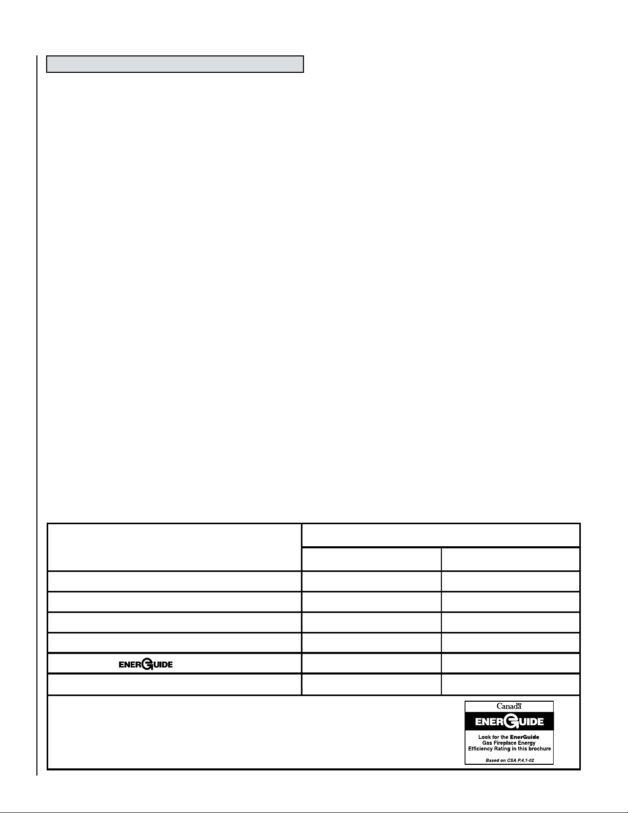
RATINGS
Max/Min Input BTUh 0-2,000 Feet (0-610 M)u
Manifold Pressure (IN. WC)
Min. Inlet Pressure (IN. WC)
Maximum heat output BTUs/hour-steady state
P4 Efficiency
Orifice (DMS) 0-2,000 Feet (0-610 M)u
uUnit factory equipped for 0-2000 FT/0-610 M, In Canada 0-4500 FT/0-1370 M
vThe Steady State Efficiency numbers based on maximum vent configuration.
wTested to CSA P.4.1-02 “Testing Method for Measuring Annual Fireplace Efficiency.
Electrical Rating: 120 VAC, 60 HZ, Less Than 2 Amps
6
w
Forced Air Duct Kit
Whole Home Comfort
System
Model Ravelle 42
NATURAL GAS LP GAS
42,000 / 29,500 36,000 / 25,000
3.5 / 1.7 10 / 5.1
5 11
34,860 29,880
50.43% 53.47%
#30 #49
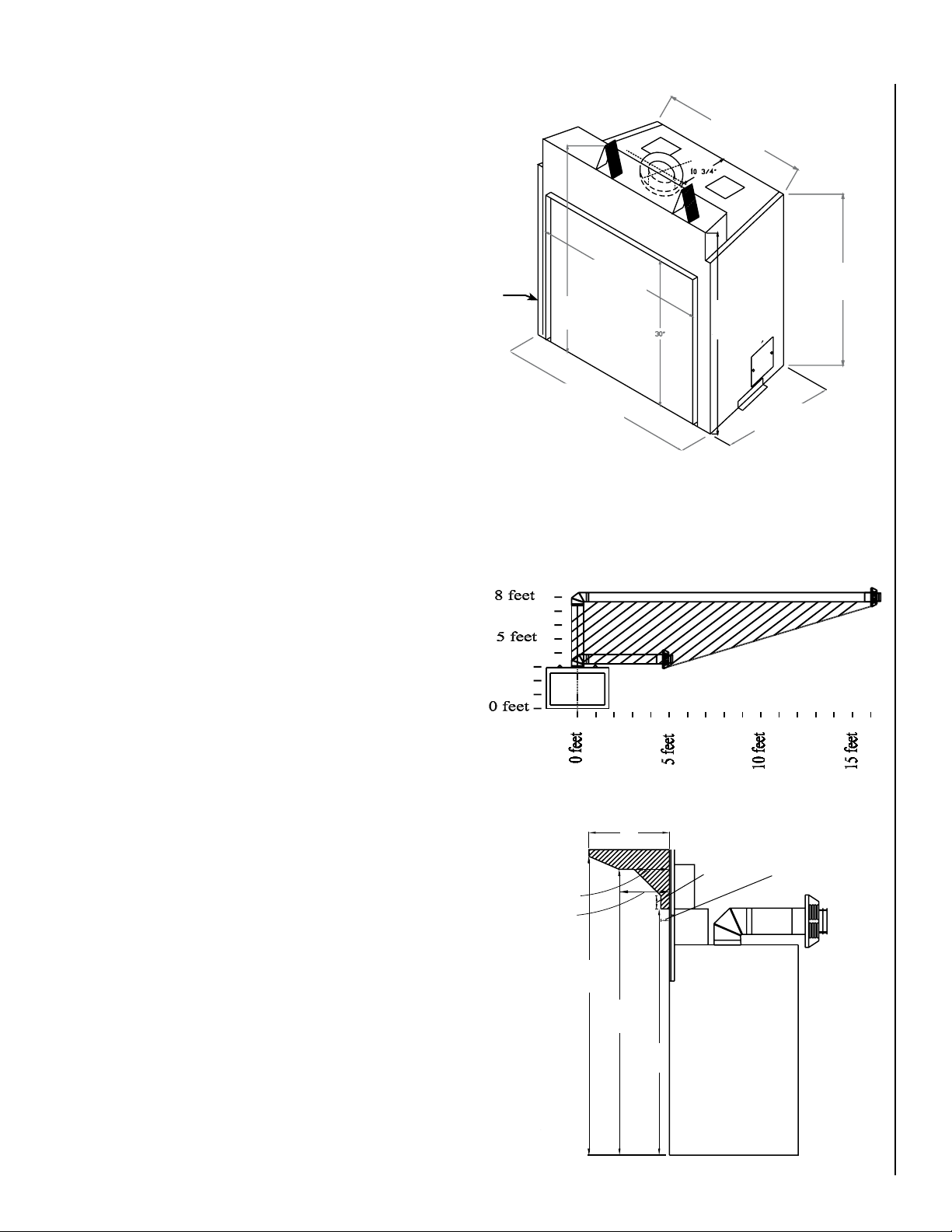
Preparing Your Ravelle™ 42 Fireplace For Installation
*
*
Installations in the shaded
area require five inches
clearance on top of pipe.
Fireplace side view
(drawing not to scale)
Base of Fireplace
Dimensions
Read all instructions before beginning your installation. If instructions
have not been read carefully, your installation could void your warranty
and may create a serious fire, health, or other safety hazard.
The Lennox Hearth Products warranty will be voided if one of the following occurs:
• Installation of any damaged fireplace or vent system component.
• Unauthorized modification of the direct-vent system.
• Installation other than as instructed by Lennox Hearth Products,
Security™, or Simpson Dura-Vent.
• Installation of any fireplace or vent system component not manufactured or approved by Lennox Hearth Products, Security™ or
Simpson Dura-Vent.
When planning the installation for your Ravelle 42 gas fireplace, it’s
necessary to consider the following:
• Where the unit is to be installed
• The vent system configuration to be used
• Gas supply (NG or LP)
• Electrical wiring
• Framing and finishing
• Optional accessories
Clearances to Combustibles
Minimum clearances include any projections such as shelves, window
sills, mantels, spacers/standoffs or surfaces to combustible construction
etc. above the appliance. Paint or lacquer used to finish the mantel
must be heat resistant in order to avoid discoloration.
29-3/4”
w
35-1/2”
(902mm)
41”
(1041mm)
u
(756mm)
38-1/4”
(972mm)
47-3/4”
(1213mm)
v
43”
(1092mm)
Figure 1
uThe center of the access hole for the gas piping is located at the
left side of the fireplace 6-7/8” back from the front edge and 2-1/8”
up from the base of the unit.
vThe electrical access is located at the right lower rear of the fire-
place.
w These dimensions include the 3/4” stand-offs.
20-3/4”
(527mm)
w
Minimum clearances to combustible materials in inches:
Front corners to enclosure (from stand-offs) 0 (0mm)
Rear corners to enclosure (from stand-offs) 0 (0mm)
Top to header (from stand-offs) 0 (0mm)
Bottom of unit to floor 0 (0mm)
Edge of door glass to side wall and side trim 7-1/2 (191mm)
Back to enclosure (from stand-offs) 0 (0mm)
Mantel: The drawing at the lower right shows the minimum distances
from the base of the fireplace to combustible mantel and facing material.
Combustible materials may be placed above and within the shaded areas.
If your fireplace has an arched face, the combustible mantel facing material may curve with the arch of the face as long as a minimum distance
of 10” is maintained between the top of the face and the combustible
facing material.
Hearth Protection: Hearth protection in front of the Ravelle™ 42 gas
fireplace is not required. However, hearth protection is recommended
and will enhance the appearance of the fireplace.
Pipe Clearances: All installations using a vertical termination cap
must maintain 1” (25mm) clearance between the direct-vent pipe and
combustibles. For horizontal terminations, when the top of the horizontal
run of pipe is less than 8 feet (2.4 M) above the base of the fireplace, 1”
(25mm) clearance on the sides and bottom and 5” (127 mm) on the top
of the pipe is required. For those horizontal runs at or above 8 feet, 1”
(25 mm) is required on the sides and bottom and 2” (51 mm) on the top
of the pipe. See Page 19 for allowable pipe configurations.
NOTE: DIAGRAMS & ILLUSTRATIONS ARE NOT TO SCALE.
(133mm)
Figure 2
Mantel and Facing Material (side view)
12”
(305mm)
(51mm)
5-1/4”
7-1/2”
(191mm)
49-5/8”
(1261mm)
47-5/8”
(1210mm)
41-5/8”
(1057mm)
2”
1-1/4”
(32mm)
7
C/L
INSTALLATION
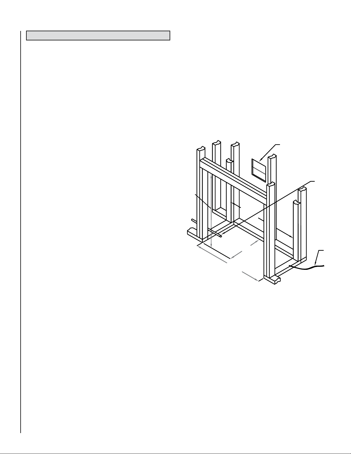
Framing Dimensions
The dimensions given on this page are minimum framing distances necessary to maintain safe clearances between the Ravelle™ 42 gas fireplace
and combustible materials.
uIf the unit is to be vented horizontally with a 90º elbow right off the
top of the fireplace and directly through an exterior wall, then a hole
10-3/4” (273 mm) square with a center line 42-1/4” (1073 mm)
above the base of the fireplace will accommodate the wall thimble
and direct-vent pipe.
vThe gas line should be routed to the left side of the unit. The access
hole in the fireplace for the gas line is 6-7/8” (175 mm) back from
the front edge and 2-1/8” (54 mm) up from the base of the unit. If
the gas line enters the unit from the right side the piping will need to
be disconnected to remove the fan.
If a wall-mounted on/off switch or thermostat is to be used, these
wires should be routed to the left front of the unit for access to the
fireplace. The wire should be fed through the gas line hole, along the
gas line, to the valve.
A 6” (152 mm) header may need to be notched to accommodate vertical
vent pipe. If the fireplace is going to be horizontally vented directly out
the back, do not place a stud in line with the wall thimble. If a hearth
extension greater than 1” (25 mm) thick is going to be used, the fireplace and the header must be raised accordingly. See Hearth Extension
Considerations for further details.
Insulation: The exterior walls adjacent to the fireplace should be
insulated like the rest of the house, but insulation should not be placed
around the fireplace or vent pipe.
Corner Installations: The dimensions on this page are minimum and
show the stand-offs on the rear corners of the fireplace up against the
corner walls.
u
48”
(1219mm)
v
wThe electrical power supply wiring should be routed to the right rear
of the unit.
Note: The fireplace may be placed directly on wood or non-combustible
flooring, but not on vinyl floor covering or carpet.
Framing Suggestions: The framing header above the front of the
fireplace should be as narrow front to back as allowable to give maximum
clearance to the direct-vent pipe (i.e. don’t use a 6” (152 mm) thick header
when a 4” (102 mm) thick one is allowed).
Figure 3
44-1/2”
(1130mm)
44-1/2”
(1130mm)
21”
(533mm)
w
8
NOTE: DIAGRAMS & ILLUSTRATIONS ARE NOT TO SCALE.
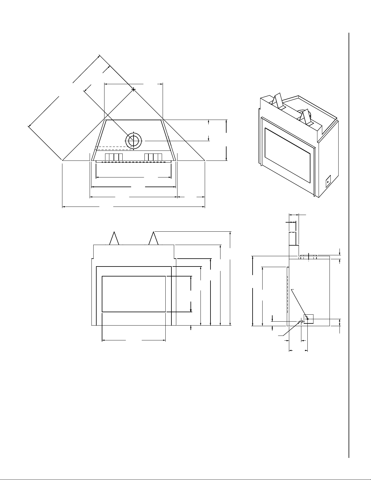
18-9/16
(471)
14
(356)
44-1/2
(1130)
51-1/4
(1302)
29-3/4
(756)
20-3/4
(527)
47-3/4
(1213)
35-1/2
(902)
2
(51)
34
(864)
41
(1041)
38-1/4
(972)
30
(762)
43
(1092)
30
(762)
3-1/2
(89)
9-1/2
(241)
10-3/4
(273)
72-1/2
(1842)
6-7/8
(175)
18-3/16
(462)
32-5/16
(821)
3-1/2
(89)
5
(127)
6-1/4
(159)
2-1/4
(57)
GAS INLET
ELECTRICAL
INLET
Fireplace Dimensions
Corner Installation
Framing Details
Inches (millimeters)
Figure 4
NOTE: DIAGRAMS & ILLUSTRATIONS ARE NOT TO SCALE.
9
Base of Fireplace
One Inch Space
Fireplace
Face
Raised
Platform
Nailing
Plate
Raised Installations
Raised Platform
for Hearth Extension and Fireplace
Hearth Extension Considerations
The fireplace may be raised by building a platform of sufficient strength to
support the fireplace and pipe. When building a raised hearth extension,
please see the note below regarding height of the fireplace in relation to
the thickness of the hearth extension material.
A hearth extension in front of the fireplace is not required; however, to
enhance the appearance of the Ravelle™ 42 gas fireplace, one is recommended. Note: There is a 1” (25 mm) space between the base of the
fireplace and the bottom of the decorative fireplace face. This space
will allow a 7/8” (22 mm) thick hearth extension (including backer board
if desired). Should a hearth extension thicker than 7/8” (22 mm) be
desired, the height of the fireplace must be raised the thickness of that
hearth extension less the 7/8” (22 mm). For example, if a 2-7/8” (73 mm)
thick cultured stone is to be placed on the floor to serve as the hearth
extension, then the fireplace must be raised 2” (51 mm) (possibly using
1/2” (13 mm) plywood over 2 x 4’s laid flat) to accommodate the 2-7/8”
(73 mm) stone. It is important to note that if the fireplace is raised then
it is necessary to raise the height of the header above the stand-offs
an equal amount. If you wish to install your fireplace without a hearth
extension you must remember to set your finished flooring height 1” (25
mm) higher than the bottom base of the fireplace or install the fireplace
1” (25mm) lower than the finished flooring materials for that room. This
will assure that no gap will exist between the room’s flooring and your
new fireplace decorative face after it is installed.
Raised Platform
for Hearth Extension
and Fireplace
Figure 5
Raised
Platform
Nailing
Plate
Fireplace
Face
Base of Fireplace
One Inch Space
Figure 7
Figure 6
10
NOTE: DIAGRAMS & ILLUSTRATIONS ARE NOT TO SCALE.
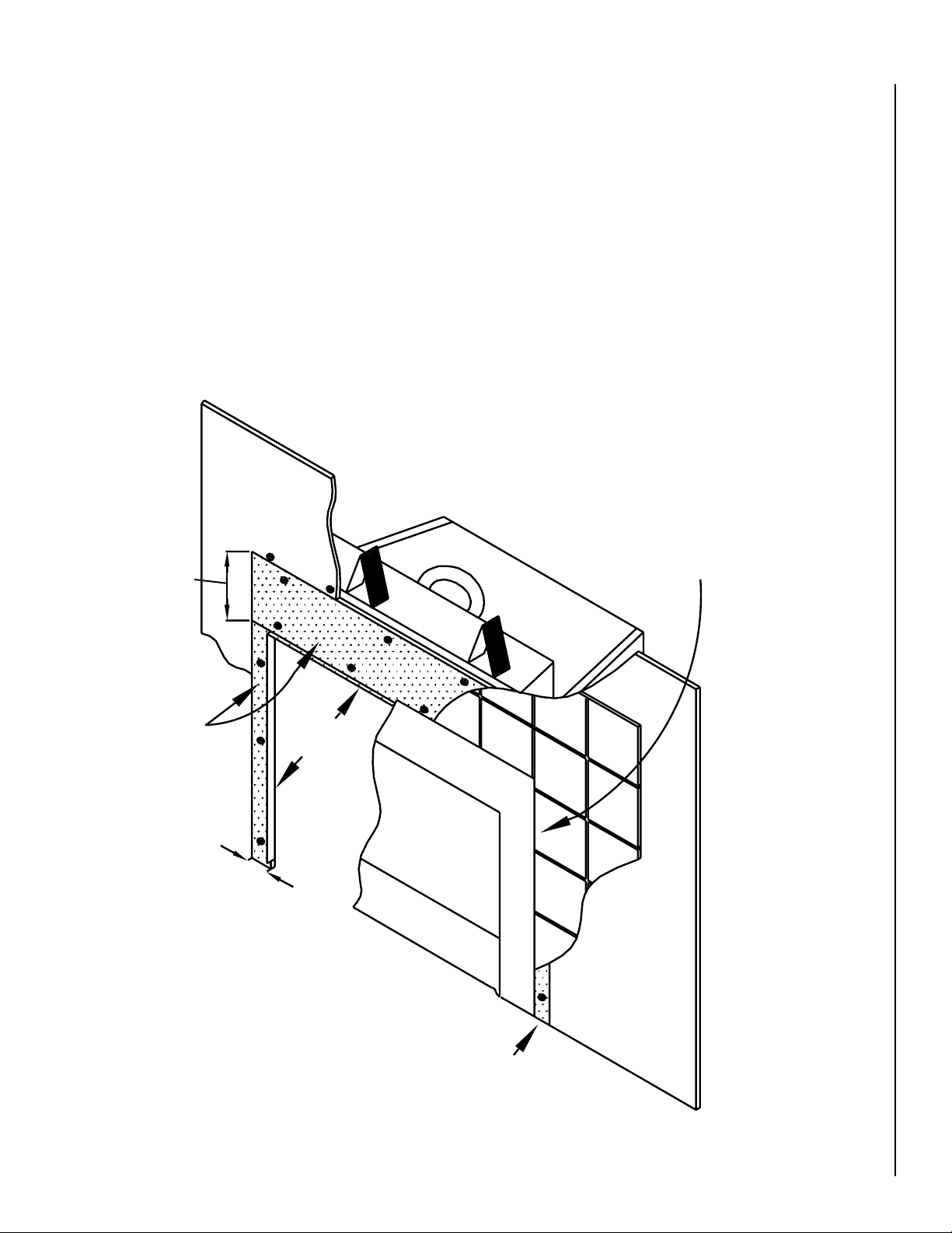
Facing Installation Considerations
Cement Board
3/8” Tile and 1/2” Cement
Board Behind Fireplace Face
Cement Board - a minimum
of five inches wide.
Sheetrock
1” Reveal
5” (127mm)
Minimum
Sheetrock
Non-combustible cement board (such as Wonderboard, Durock, or Hardybacker) must extend 10” (254 mm) above the 1” (25 mm) top reveal
and a minimum of 3” (76 mm) from each side reveal (see Figure 8). This
cement board may be 1/4” (6.3 mm) thick or greater, but would normally
be the thickness of the drywall - for example 1/2” (13 mm). The cement
board may be fastened by drywall screws.
Sheetrock
The screws should be driven through the cement board into the outer
metal skin of the fireplace. The sheetrock (drywall) is then butted up
to the cement board. The sheetrock above the fireplace should also be
fastened to the fireplace by driving screws into the outer metal skin of
the fireplace.
Facing Less Than 1” Thick: If the combined thickness of the facing
material (eg. 3/8” [9.5 mm] thick ceramic tile and 1/2” [13 mm] thick
cement board) is less than 1” (25mm), then the tile can be placed behind
the fireplace face (see below).
10” (254mm)
Minimum
Cement Board
3” (76mm)
Minimum
3/8” (9.5mm) Tile and 1/2” (12.7mm) Cement Board
Behind Fireplace Face
(25mm)
1” Reveal
Sheetrock
Figure 8
Cement Board - Minimum
of 3” (76mm) Wide
NOTE: DIAGRAMS & ILLUSTRATIONS ARE NOT TO SCALE.
11
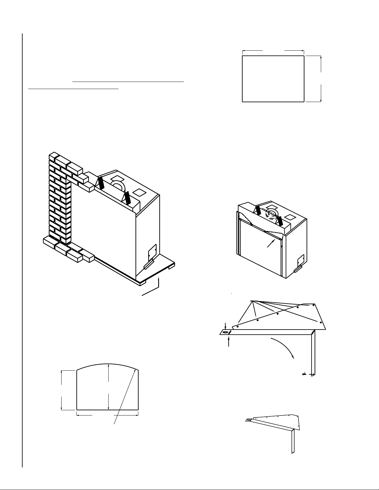
Facing Greater Than 1” (25mm) Thick:
Reveal Corner
Template
A
B
C
Expanded View of Reveal Corner
A
If the combined thickness of the facing material (eg. brick or cultured
stone) and concrete board is greater than 1”, then the facing material
must be placed around the face. A template (Arch #75098, Foundry™
#75035 and Classic [Louver] #75101) should be used while installing
the facing material. Templates for the various faces may be purchased
from your Lennox Hearth Products dealer or a template may be made of
plywood using the dimensions listed on this page. If you choose to make
a template, 1/8” (3mm) must be added to each side and top dimension
to provide sufficient clearance so the face may be removed for access to
the firebox. Since the bottom of the fireplace face is 1” above the base
of the fireplace, 1” (25mm) must be added to the height of the template
if the template is to rest on the floor or platform on which the fireplace
is placed. It is extremely IMPORTANT that the template be centered left
to right on the glass door of the fireplace.
Traditional Face
41”
(1041mm)
30-5/8”
(778mm)
Figure 12
Adjustment prior to arched face installation:
The corners of the 1” (25mm) reveal around the fireplace opening need
to be adjusted prior to installing an arched face (see Figures 13 and
14). Remove screws A and loosen screw B. Rotate the corner downward
bending the metal at pivot point C until the holes from which screws A
were removed line up with the lower set of holes. Reinstall screws A and
tighten screw B. When finished, the corners should look like the corner
shown in Figure 15.
Platform to raise fireplace to accommodate a
hearth extension greater than 1” in thickness.
Figure 9
The fireplace face dimensions are:
26-3/8”
(670mm)
Template
Arch Face
30-5/8”
(778mm)
41”
(1041mm)
51-1/2” R
(1308mm)
Figure 13
Figure 14
Reveal Corner
A
B
C
Expanded View of
Reveal Corner
A
Reveal Corner Adjusted
for Arch Face
Figure 10
12
Figure 15
NOTE: DIAGRAMS & ILLUSTRATIONS ARE NOT TO SCALE.
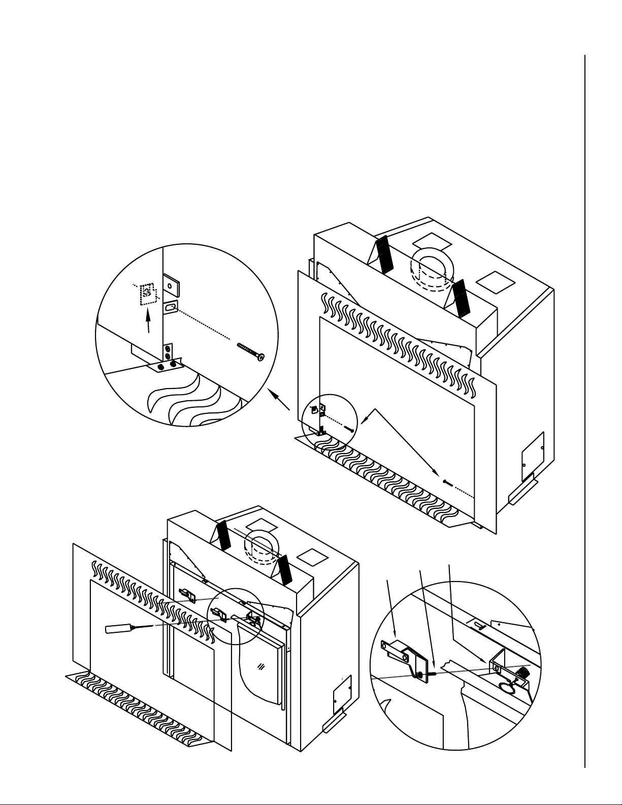
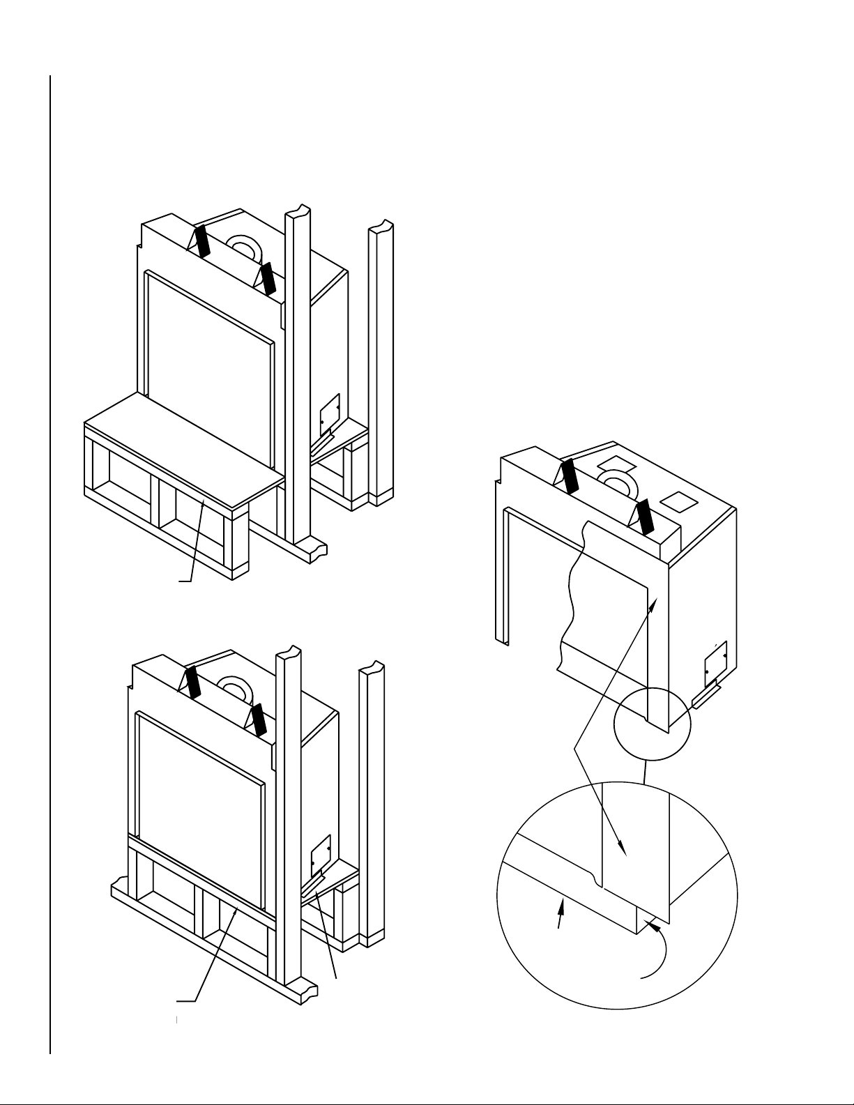
Face Installation
A
B
C
D
E
Expanded View
Expanded View
A number of different faces are available for the Ravelle™ 42 gas fireplace, however, all the faces are installed in a similar manner. A total of
four screws (two upper and two lower) attach the face to the fireplace.
To install a face:
1. Locate the two screws found in the hardware bag shipped with the face.
Position the face (with the lower door open) in front of the fireplace.
Install the two screws, A in the diagram below, through the holes in
the lower door hinge bracket and screw them into the captive nut on
tab B located on the fireplace. Do not fully tighten these screws yet.
B
2. Bracket C in the diagram below is installed on the face during the face
assembly (see instructions included with face). The captive screws D
on this bracket should be screwed into captive nuts E on the fireplace.
A phillips head screwdriver inserted through the vent holes in the face
can be used to complete this task. Align the face for plumb and level
and then tighten all four screws.
CAUTION: Any masonry that has been cleaned with an acid
wash must be properly neutralized before installing the fireplace face. The acid wash will tarnish the face. Consult your
masonry installer.
Expanded View
A
E
C
D
Figure 16
NOTE: DIAGRAMS & ILLUSTRATIONS ARE NOT TO SCALE.
Expanded View
13
 Loading...