


GB
D
F
I
E
P
NL
DK
S
FIN
TR
RUS
PFH 20 E
PFH 20 QE
PFH 24 QE
Instructions for use
Please read and save these
instructions.
Gebrauchsanleitung
Bitte lesen und aufbewahren.
Instruction d’utilisation
Prière de lire et de conserver.
Istruzioni d’uso
Si prega di leggere le istruzioni e
di conservarle.
Instrucciones de uso
Lea y conserve estas
instrucciones por favor.
Instruções de serviço
Por favor leia e conserve em seu
poder.
Gebruiksaanwijzing
Lees en let goed op deze
adviezen.
Brugsanvisning
Vær venlig at læse og opbevare.
Bruksanvisning
Var god läs och tag tillvara dessa
instruktioner.
Käyttöohje
Lue ja säilytö
Kullanøm kølavuzu
Lütfen okuyun ve saklayin
Инструкция по
использованию
Пожалуйста, прочтите и
сохраните настоящую
инструкцию

1
ENGLISH
PFH 20 E, PFH 20 QE, PFH 24 QE
You are demanding and expect to purchase quality goods – quality offered by
Milwaukee.
We have built a durable and reliable electric power tool for you.
Please read the instructions for use before first operation so you can handle your
power tool effectively and safely.
We are sure that buying an Electric Power Tool from Milwaukee was the right choice!
PFH 24 QE PFH 20 QE PFH 20 E
Nominal power 620 W 560 W 560 W. . . . . . . . . . . . . . . . . . . . . . . . . . . . . . . .
No-load speed 0–1290 min
-1
0–1150 min
-1
0–1150 min
-1
. . . . . . . . . . . . . . . . .
Speed under load max. 1000 min
-1
810 min
-1
810 min
-1
. . . . . . . . . . . . . . . . . .
Rate of percussion under
load max. 4300 min
-1
3450 min
-1
3450 min
-1
. . . . . . . . . . . . . . . . . . . . . . . . . . .
Drilling capacity in
Concrete 24 mm 20 mm 20 mm. . . . . . . . . . . . . . . . . . . . . . . . . . . . . . . . . . . .
Steel 13 mm 13 mm 13 mm. . . . . . . . . . . . . . . . . . . . . . . . . . . . . . . . . . . . . . .
Wood 30 mm 30 mm 30 mm. . . . . . . . . . . . . . . . . . . . . . . . . . . . . . . . . . . . . .
Chuck neck diameter 43 mm 43 mm 43 mm. . . . . . . . . . . . . . . . . . . . . . . . . .
Weight 2,3 kg 2,3 kg 2,3 kg. . . . . . . . . . . . . . . . . . . . . . . . . . . . . . . . . . . . . . . . .
J Please pay attention to the safety instructions in the attached leaflet!
J Dust that arises when working on material containing asbestos or stonework
containing crystalline silicic acid is harmful to the health. Please follow accident
prevention regulations.
J Appliances used at many different locations including open air must be connected
via a current surge preventing switch.
J Always wear goggles when using the machine. It is recommended to wear gloves,
sturdy non slipping shoes and apron.
J Sawdust and splinters must not be removed while the machine is running.
J Do not pierce the motor housing as this could damage the double insulation (use
adhesives).
J Always disconnect the plug from the socket before carrying out any work on the
machine.
Only plug-in when machine is switched off.
J Keep mains lead clear from working range of the machine. Always lead the cable
away behind you.
J Always use the auxiliary handle, even if the machine has a safety clutch since this
safety clutch only engages when the machine blocks with a jerk.
J Do not use diamond core drills on hammer mode.
J When drilling in walls ceiling, or floor, take care to avoid electric cables and gas or
waterpipes.
Typically the A-weighted noise levels of the tool are:
Sound pressure level = 87 dB(A) (PFH20E, PFH20QE), 88dB(A) (PFH24QE).
Sound power level = 100dB(A) (PFH20E, PFH20QE), 101dB(A) (PFH24QE).
Wear ear protectors! Measured values determined according to EN 50 144.
Typically the weighted acceleration is 10 m/s
2
(PFH20E, PFH20QE),
11m/s
2
(PFH24QE). Measured values determined according to EN 50 144.
The rotary pneumatic hammer can be used for hammer drilling and drilling in wood,
metal as well as plastic.
Do not use this product in another way as stated for normal use.
A pneumatic percussion unit generates the necessary power for hammer-drilling in
masonry.
Just as one hits a conventional chisel with a hammer, so a free piston strikes the
percussion drill which is free to move longitudinally, via an intermediate punch. This
free piston is actuated by an electric motor driven piston via an air buffer. This
electromagnetic principle provides a high degree of percussion elasticity and work
that is free of recoil.
In contrast to an ordinary percussion drill, the drilling performance is not dependent
on the pressure exerted on the machine.
Introduction
Technical Data
Advice for your
safety
Measured sound
value
Measured
vibration value
Use
Function of
rotary pneumatic
hammer

2
ENGLISH
PFH 20 E, PFH 20 QE, PFH 24 QE
Always disconnect the plug from the socket before carrying out any work on the
machine.
The following tools can be inserted in the drill-hammer chuck using the SDS-plus
shank:
–Hammer-drill for concrete and brickwork
–Adapter for geared drill chuck or
screwdriver bits
Only use accessories with SDS-plus shank!
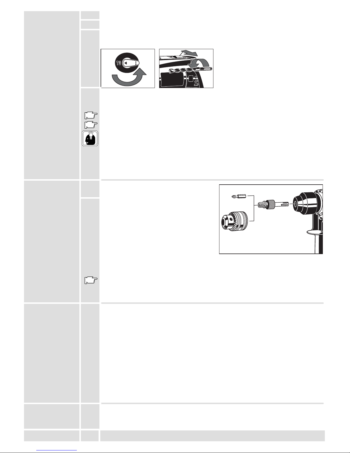
1. Clean and grease the shank of the bit.
Special grease can be obtained as
accessory
2. Push bit into chuck turning it slightly, the
chuck locks the bit in to the chuck
automatically.
3. Check that the bit is properly locked into
place. It must be possible to move it back
and forth.
Brief description
Built-in safety clutch helps prevent the machine from
rotating if the drill bit jams.
Hammer drilling chuck for bits and
accessories with SDS-plus reception – tools
are locked automatically after insertion.
Selector lever for switching between
drilliing and hammer drilling.
Fully insulated gear box for long durability and protection
from electric shock.
Modifications: Text, diagrams and data are correct at the time of
printing. In the interest of continuous improvement of our products,
technical specifications are subject to alteration without prior
notice.
Ergonomically designed housing
with soft grip.
Auxiliary handle, has an integral
depth gauge and can be rotated in
various positions.
Lock button for switch locking
Switch trigger for switching the
machine on and off, and for smooth
starting and varying speed. (Depending
on equipment)
Quick–Lok – fast exchange of power
supply cables for the use of different
cable lengths or for fast replacing of
defect cables. (Depending on equipment)
Reversing lever for changing
from forward to reverse rotation –
due to a lockout mechanism,
switching the lever is only
possible if the On-/Off switch is
not depressed.
Tool reception
Inserting tools

3
ENGLISH
PFH 20 E, PFH 20 QE, PFH 24 QE
4. Pull back plastic ring in direction of arrow
and remove bit.
The auxiliary handle can be rotated in
steps of 30°. Make sure that the handle is
locked in position at the chuck drive.
For drilling the required depth, insert the
depth gauge into the provided boring in the
handel and fasten it at the required drilling
depth.
Hammer-drilling:
Switch to this position . . . .
Drilling without hammer:
Switch to this position . . .
To help the lever lock into position twist the
inserted bit slightly while turning lever.
Do not switch when the machine is under
load.
During no-load operation the pneumatic
hammer mechanism is not yet activated
even if the hammer mechanism is switched on. To activate the pneumatic hammer
mechanism all you have to do is to firmly push the running machine against the
work material. This unlocks the snap die from the safety device, and drilling with
light pressure is now possible.
Only switch over when the machine is stationary or slowing down.
Only operate the machine rotating to the right when hammer-drilling
When using the adaptors always turn the hammer function off.
Tool removal
Positioning the
auxiliary handle
Setting the
depth gauge
Switching over
drilling
hammer drilling
2
1

4
ENGLISH
PFH 20 E, PFH 20 QE, PFH 24 QE
Move the lever to the required symbol:
Forward rotation
. . . . . .
(Drilling / Screwing)
Reverse rotation
. . . . .
Due to a lockout mechanism, the reversing
lever can only be switched when the
On-/off switch is not depressed.
Only change direction of rotation when the machine
has stopped.
Only operate the machine rotating to the right when hammer-drilling
Connect only to a single-phase AC current supply and only to the mains voltage
specified on the rating plate. Connection to sockets without earth protection is
possible as the appliance features protective insulation to DIN 57 740/ VDE 0740
and CEE 20. Radio suppression complies with the European standard EN 55014.
When fitting the plug, make sure that the brown (live) wire of this appliance is
connected to the plug terminal marked L or coloured red, and the blue (neutral) wire
of this appliance is connected to the plug terminal marked N or coloured black.
Under no circumstances must the wires of this appliance be connected to the earth
terminal of the plug marked either E, with the earth symbol or coloured green or
green/yellow.
Insert the Quik–Lok power supply cable
such that the lug of the plug grasps the
relief of the socket. After inserting lock by
turning clockwise.
Intermittent use
Switching on: Press On-/off switch
Switching off: Release On-/off switch
Continuous use
Switching on: Press the On-/off switch and
then the locking button, after that release
on-off switch.
Switching off: Press the On-/off switch and
then release.
The speed can be infinitely varied by
slowly releasing/pressing the switch
trigger.
Switching
between forward
and reverse
rotation
Mains
connection
Quik–Lok power
supply cable
(only applicable
for
PFH 20 QE
PFH 24 QE)
On-/off switch
2
1

5
ENGLISH
PFH 20 E, PFH 20 QE, PFH 24 QE
1. Clean and grease the shank of the bit. Special grease can be obtained as
accessory
2. Insert the SDS-plus drill bit.
3. Make the following settings
hammer drilling forward rotation
4. Apply the machine to the working material when switched off, then switch the
machine on, activate the pneumatic hammer mechanism with short pressure of the
machine against the material, and continue to work applying light pressure.
Exerting greater pressure does not increase the machine’s effectiveness!
When hammer-drilling overhead, use the dust cap (accessory).
Take the drill out of the hole from time to time to remove dust.
Switch to percussion-drilling for concrete, hard bricks and tiles, stone, hard cement,
and marble (but not when drilling the surface of marble).
For tiles, paving-stones, soft bricks and tiles, soft cement, breeze-block and plaster,
switch to normal drilling.
Use percussion carbide tipped masonry drill-bits.
When drilling a hard, smooth surface (e.g. tiles), cover the point to be drilled with
adhesive tape in order to prevent the drill bit tip from skidding.
1. Fit the mounting shaft into the
drill-hammer chuck as described above.
2. If the mounting shaft has an adjustable
metal ring (i.e. if included in the set), the
longitudinal play of the SDS-plus mounting
can be compensated for. To do this, turn
the metal ring of the mounting shaft
anti-clockwise as far as it will go.
Drill chucks with 1/2” x 20 UNF mounting
threads can be screwed onto the mounting
shaft. Screwdriver bits can be inserted directly into of the mounting shaft.
When using the adaptors always turn the hammer function off.
*Not included in standard equipment, available as an accessory.
If the carbon brushes cut-out or the hammer capacity declines please contact your
authorized Milwaukee service station. This will ensure long service life as well as
constant readiness for working of the machine.
The location of your nearest service station is shown in our “Service adresses” leaflet
attached to each product.
The ventilation slots of the machine must be kept clear at all times.
Use only Milwaukee accessories and spare parts. Should components need to be
exchanged which have not been described, please contact one of our Milwaukee
service agents (see our list of guarantee/service addresses).
If needed, an exploded view of the tool can be ordered. Please state the ten–digit
No. as well as the machine type printed on the label and order the drawing at your
local service agents or directly at: Atlas Copco Electric Tools GmbH, Postfach 320,
D–71361 Winnenden.
The range of accessories with part numbers is shown in our catalogue.
How to drill in
stone
Hints
Mounting shaft
for three jaw
chuck or
screwdriver bits
(Accessory*)
Maintenance
Accessories

6
DEUTSCH
PFH 20 E, PFH 20 QE, PFH 24 QE
Sie sind anspruchsvoll und erwarten Qualität, die Ihnen Milwaukee bietet.
Für Sie haben wir ein haltbares und möglichst sicheres Elektrowerkzeug gebaut.
Bitte lesen Sie vor Inbetriebnahme Ihres Gerätes die Gebrauchsanleitung, um Ihr
Elektrowerkzeug effektiv und gefahrlos nutzen zu können.
Wir sind sicher, daß Sie mit Elektrowerkzeugen von Milwaukee Ihre richtige Wahl
getroffen haben.
PFH 24 QE PFH 20 QE PFH 20 E
Nennaufnahme 620 W 560 W 560 W. . . . . . . . . . . . . . . . . . . . . . . . . . . . . . .
Leerlaufdrehzahl 0–1290 min
-1
0–1150 min
-1
0–1150 min
-1
. . . . . . . . . . . . . . .
Lastdrehzahl max. 1000 min
-1
810 min
-1
810 min
-1
. . . . . . . . . . . . . . . . . . . . . .
Lastschlagzahl max. 4300 min
-1
3450 min
-1
3450 min
-1
. . . . . . . . . . . . . . . . . .
Bohr-ø in
Beton 24 mm 20 mm 20 mm. . . . . . . . . . . . . . . . . . . . . . . . . . . . . . . . . . . . . .
Stahl 13 mm 13 mm 13 mm. . . . . . . . . . . . . . . . . . . . . . . . . . . . . . . . . . . . . . .
Holz 30 mm 30 mm 30 mm. . . . . . . . . . . . . . . . . . . . . . . . . . . . . . . . . . . . . . . .
Spannhals-ø 43 mm 43 mm 43 mm. . . . . . . . . . . . . . . . . . . . . . . . . . . . . . . . . .
Gewicht 2,3 kg 2,3 kg 2,3 kg. . . . . . . . . . . . . . . . . . . . . . . . . . . . . . . . . . . . . . . .
J Sicherheitshinweise der beiliegenden Broschüre beachten!
J Staub der bei der Bearbeitung von asbesthaltigen Materialien und Gestein mit
kristalliner Kieselsäure entsteht, ist gesundheitsschädlich. Beachten Sie die
Unfallverhütungsvorschriften VBG 119 der Berufsgenossenschaft.
J Steckdosen in Außenbereichen müssen mit Fehlerstrom-Schutzschaltern
ausgerüstet sein. Das verlangt die Installationsvorschrift für Ihre Elektroanlage. Bitte
beachten Sie das bei der Verwendung unseres Gerätes – sprechen Sie mit Ihrem
Elektroinstallateur.
J Beim Arbeiten mit der Maschine stets Schutzbrille tragen. Schutzhandschuhe, festes
und rutschsicheres Schuhwerk und Schürze werden empfohlen.
J Späne oder Splitter dürfen bei laufender Maschine nicht entfernt werden.
J Gehäuse der Maschine nicht anbohren, da sonst die Schutzisolierung unterbrochen
wird (Klebeschilder verwenden).
J Vor allen Arbeiten an der Maschine Stecker aus der Steckdose ziehen.
Maschine nur ausgeschaltet an die Steckdose anschließen.
J Anschlußkabel stets vom Wirkungsbereich der Maschine fernhalten. Kabel immer
nach hinten von der Maschine wegführen.
J Stets den Zusatzhandgriff verwenden. Dies gilt auch bei Maschinen mit
Sicherheitskupplung, da diese Sicherheitskupplung nur bei ruckartigem Blockieren
anspricht.
J Bei Arbeiten mit Diamantbohrkronen Schlagwerk ausschalten.
J Beim Bohren in Wand, Decke oder Fußboden auf elektrische Kabel, Gas- und
Wasserleitungen achten.
Der A-bewertete Geräuschpegel des Gerätes beträgt typischerweise:
Schalldruckpegel = 87 dB(A) (PFH20E, PFH20QE), 88dB(A) (PFH24QE).
Schalleistungspegel = 100dB(A) (PFH20E, PFH20QE), 101dB(A) (PFH24QE).
Gehörschutz tragen! Meßwerte ermittelt entsprechend EN 50 144.
Die bewertete Beschleunigung beträgt typischerweise 10 m/s
2
(PFH20E,
PFH20QE), 11m/s
2
(PFH24QE).
Meßwerte ermittelt entsprechend EN 50 144.
Der Bohrhammer ist universell einsetzbar zum Hammerbohren in Gestein und zum
Bohren in Holz, Metall und Kunststoff.
Dieses Gerät darf nur wie angegeben bestimmungsgemäß verwendet werden.
Den erforderlichen Schlag zum Hammerbohren in Gestein erzeugt ein
Pneumatikschlagwerk.
Ähnlich wie ein Hammer, schlägt ein Flugkolben über einen Zwischendöpper direkt
auf den sich drehenden und in Längsrichtung beweglichen Hammerbohrer.
Ein vom Elektromotor angetriebener Kolben bewegt über ein Luftkissen diesen
Flugkolben.
Dieses elektropneumatische Prinzip bewirkt eine hohe Schlagelastizität und ein
rückstoßfreies Arbeiten.
Im Gegensatz zur Schlagbohrmaschine ist die Bohrleistung nicht vom Anpreßdruck
abhängig.
Vorwort
T echnische
Daten
Hinweise für
Ihre Sicherheit
Geräusch-
meßwerte
Vibrations-
meßwerte
Verwendung
Funktion des
PneumatikBohrhammers

7
DEUTSCH
PFH 20 E, PFH 20 QE, PFH 24 QE
Vor allen Arbeiten an der Maschine Stecker aus der Steckdose ziehen.
In das Hammerbohrfutter können folgende Arbeitswerkzeuge mit SDS-plus-Schaft
eingesetzt werden:
- Hammerbohrer für Beton und Gestein
- Aufnahmeschaft für Zahnkranzbohrfutter oder Schrauberbits
Nur Werkzeuge mit SDS-plus-Schaft verwenden!
1. Werkzeugschaft säubern und einfetten.
Spezialfett ist als Zubehör erhältlich.
2. Werkzeug leicht drehend bis Anschlag
einschieben; das Bohrfutter verriegelt
automatisch.
3. Prüfen ob Werkzeug richtig verriegelt ist.
Es muß sich in Längsrichtung ca. 10 mm
bewegen lassen.
Kurzbeschreibung
Eingebaute Sicherheitskupplung, verhindert ein
Mitdrehen der Maschine bei Verklemmen des Bohrers.
Hammerbohrfutter für Werkzeuge mit
SDS-plus Aufnahme – Werkzeuge werden
nach dem Einstecken automatisch verriegelt.
Schalthebel zum Umschalten
zwischen Bohren und Hammerbohren.
Vollisolierter Getriebekasten für lange Lebensdauer und
Schutz vor elektrischem Schlag.
Änderungen: Text, Bild und Daten entsprechen dem technischen
Stand zur Zeit des Drucktermins. Änderungen im Sinne der
Weiterentwicklung unserer Produkte sind vorbehalten.
Ergonomisch geformtes Gehäuse
mit Softgrip für ermüdungsarmes
Arbeiten.
Verstellbarer Zusatzhandgriff mit
integriertem Tiefenanschlag.
Arretierknopf zum Feststellen des
Schalterdrückers.
Schalterdrücker zum Ein- und
Ausschalten der Maschine und
stufenlosem elektronischem
”Gasgeben”. (Je nach Ausstattung)
Quik-Lok – Kabelschnellwechselsystem
zum Einsatz unterschiedlicher
Kabellängen bzw. zum schnellen Ersatz
defekter Kabel. (Je nach Ausstattung)
Umschalter Rechts-Linkslauf
durch Schaltsperre nur bei nicht
gedrücktem Schalterdrücker
schaltbar.
Werkzeugaufnahme
Werkzeuge
einsetzen

8
DEUTSCH
PFH 20 E, PFH 20 QE, PFH 24 QE
4. Kunststoffring in Pfeilrichtung nach hinten
ziehen und Werkzeug entnehmen.
Der Zusatzhandgriff ist in 30o-Schritten
verdrehbar.
Beim Festziehen darauf achten, daß der
Zusatzhandgriff in die Verdrehsicherung am
Spannhals einrastet.
Zum Bohren auf eine bestimmte Tiefe
Tiefenanschlag in die Bohrung am
Handgriff schieben und um die
gewünschte Bohrtiefe (versetzt zum
Bohrer) festklemmen.
Hammerbohren:
Umschalter in Stellung . . .
Bohren ohne Schlag:
Umschalter in Stellung . . .
Beim Umschalten mit dem Schalthebel
das eingesetzte Werkzeug leicht
verdrehen, dadurch wird das Einrasten
des Schalthebels erleichtert.
Maschine nicht unter Last schalten.
Im Leerlauf ist das Pneumatikschlagwerk
trotz eingeschalteter Hammerfunktion
noch nicht aktiv. Um das Pneumatikschlagwerk zu aktivieren, genügt ein kurzer,
kräftiger Druck der eingeschalteten Maschine gegen das Material. Hierbei löst sich
der Döpper spürbar aus seiner Fangvorrichtung und man kann jetzt mit leichtem
Druck arbeiten.
Nur im Stillstand oder im Auslauf der Maschine umschalten.
Beim Hammerbohren Maschine nur im Rechtslauf betreiben!
Bei Verwendung des Aufnahmeschafts Hammerbohrfunktion immer abschalten.
Werkzeuge
herausnehmen
Zusatzhandgriff
verdrehen
Einstellen des
Tiefenanschlags
Umschalten:
Bohren
Hämmern
2
1

9
DEUTSCH
PFH 20 E, PFH 20 QE, PFH 24 QE
Umschalter dem entsprechenden Symbol
gegenüberstellen:
Rechtslauf
. . . . . . .
(Bohren / Schraube eindrehen)
Linkslauf:
. . . . . . . .
(Schraube herausdrehen)
Durch eine Schaltsperre ist der
Umschalter nur bei nicht gedrücktem
Ein-/Ausschalter schaltbar.
Umschalter erst nach Auslauf der Maschine (bei
stillstehendem Motor) betätigen.
Beim Hammerbohren Maschine nur im Rechtslauf betreiben!
Nur an Einphasen-Wechselstrom und nur an die auf dem Leistungsschild
angegebene Netzspannung anschließen. Anschluß ist auch an Steckdosen ohne
Schutzkontakt möglich, da eine Schutzisolierung nach DIN 57 740/ VDE 0740 bzw.
CEE 20 vorliegt. Die Funkentstörung entspricht der Europanorm EN 55014.
Die Quik-Lok-Anschlußleitung so
einsetzen, daß die Nase des Steckers in
die Aussparung der Buchse eingreift. Nach
dem Einstecken Verriegelung
rechtsdrehend schließen.
Momentschaltung
Einschalten: Ein-/Ausschalter drücken.
Ausschalten: Ein-/Ausschalter loslassen.
Dauerschaltung
Einschalten: Ein-/Ausschalter drücken und
dann Arretierknopf drücken,
Ein-/Ausschalter loslassen.
Ausschalten: Ein-/Ausschalter drücken
und loslassen.
Die Drehzahl kann je nach Druck auf den
Schalterdrücker stufenlos verstellt werden.
Umschalten:
Rechtslauf
Linkslauf
Netzanschluß
Quik-Lok
Anschlußleitung
(nur bei
PFH 20 QE
PFH 24 QE)
Ein-/Ausschalten
2
1
10
DEUTSCH
PFH 20 E, PFH 20 QE, PFH 24 QE
1. Werkzeugschaft säubern und einfetten. Spezialfett ist als Zubehör erhältlich.
2. SDS-plus-Bohrer einsetzen.
3. Folgende Einstellungen vornehmen:
Hammerbohren Rechtslauf
4. Maschine ausgeschaltet am Material ansetzen, einschalten und mit kurzem,
kräftigem Druck Pneumatikschlagwerk aktivieren; dann mit leichtem Druck
weiterarbeiten.
Höherer Anpressdruck steigert nicht die Arbeitsleistung!
Bei Hammerbohren nach oben Staubfangteller (Zubehör) verwenden.
Von Zeit zu Zeit den Bohrer aus der Bohrung ziehen um den Staub zu beseitigen.
Bei Beton, hartem Ziegelstein, Stein, hartem Zement und Marmor auf Schlagbohren
schalten (Anbohren von Marmor jedoch ohne Schlagbohren).
Bei Fliesen, Fußbodenplatten, weichen Ziegelsteinen, Zementkalk, Schlackensteinen
und Putz auf Bohren schalten.
Beim Anbohren glatter Oberflächen (z.B. Fliesen) Bohrstelle mit Klebestreifen
bekleben um ein Abrutschen zu vermeiden.
1. Aufnahmeschaft wie zuvor beschrieben in
das Hammerbohrfutter einsetzen.
2. Bei Aufnahmeschaft mit verstellbarem
Metallring (je nach Lieferumfang) kann das
Längsspiel der SDS-plus-Aufnahme
ausgeglichen werden, hierzu Metallring
des Aufnahmeschafts entgegen
Uhrzeigersinn festdrehen.
Auf den Aufnahmeschaft können
Bohrfutter mit
1
/2”x20-UNF-Aufnahmegewinde aufgeschraubt werden.
Schrauberbits können direkt in die Bitaufnahme des Aufnahmeschafts gesteckt
werden.
Bei Verwendung des Aufnahmeschafts Hammerbohrfunktion immer abschalten.
* Im Lieferumfang nicht enthalten, empfohlene Ergänzung aus dem
Zubehörprogramm.
Bei Abschalten der Kohlebürsten oder Nachlassen der Schlagleistung: bitte
autorisierten Wartungsdienst von Milwaukee aufsuchen. Dies erhöht die
Lebensdauer der Maschine und garantiert eine ständige Betriebsbereitschaft.
Die Anschrift eines Wartungsdienstes in Ihrer Nähe entnehmen Sie bitte den
beigefügten Kundendienstadressen.
Stets die Lüftungsschlitze der Maschine sauber halten.
Nur Milwaukee Zubehör und Ersatzteile verwenden. Bauteile, deren Austausch nicht
beschrieben wurde, bei einer Milwaukee Kundendienststelle auswechseln lassen
(Broschüre Garantie/Kundendienstadressen beachten).
Bei Bedarf kann eine Explosionszeichnung des Gerätes unter Angabe der
Maschinen Type und der zehnstelligen Nummer auf dem Leistungsschild bei Ihrer
Kundendienststelle oder direkt bei Atlas Copco Electric Tools GmbH, Postfach 320,
D–71361 Winnenden angefordert werden.
Das Zubehör mit Bestellnummern ersehen Sie bitte aus unseren Katalogen.
So bohren Sie in
Gestein
Tips
Aufnahmeschaft
für
Zahnkranzbohr–
futter oder
Schrauberbits
(Zubehör*)
Wartung
Zubehör

11
FRANÇAIS
PFH 20 E, PFH 20 QE, PFH 24 QE
Vous avez des exigences et vous voulez de la qualité – une qualité que vous offre
Milwaukee. Nous avons mis au point pour vous un outil électrique de longue durée
vous offrant un maximum de sécurité. Avant la mise en service de votre appareil,
veuillez lire attentivement le mode d’emploi afin d’en tirer le plus d’efficacité et
d’éviter tout risque de danger.
Nous sommes convaincus qu’avec les outils électriques Milwaukee vous avec fait le
choix qu’il fallait.
PFH 24 QE PFH 20 QE PFH 20 E
Puissance absorbée 620 W 560 W 560 W. . . . . . . . . . . . . . . . . . . . . . . . . . .
Régime à vide 0–1290 min
-1
0–1150 min
-1
0–1150 min
-1
. . . . . . . . . . . . . . . . .
Vitesse en charge 1000 min
-1
810 min
-1
810 min
-1
. . . . . . . . . . . . . . . . . . . . . .
Perçage à percussion max. 4300 min
-1
3450 min
-1
3450 min
-1
. . . . . . . . . . . .
Ø de perçage dans
le béton 24 mm 20 mm 20 mm. . . . . . . . . . . . . . . . . . . . . . . . . . . . . . . . . . . . .
Acier 13mm 13mm 13mm. . . . . . . . . . . . . . . . . . . . . . . . . . . . . . . . . . . . . . .
Bois 30 mm 30 mm 30 mm. . . . . . . . . . . . . . . . . . . . . . . . . . . . . . . . . . . . . . . .
Ø du collier de serrage 43 mm 43 mm 43 mm. . . . . . . . . . . . . . . . . . . . . . . . .
Poids 2,3 kg 2,3 kg 2,3 kg. . . . . . . . . . . . . . . . . . . . . . . . . . . . . . . . . . . . . . . . . .
J Respecter les instructions de sécurité se trouvant dans le prospectus ci-joint.
J La poussière qui se dégage lors de l’usinage des matériaux contenant de l’amiante
et des pierres contenant de l’acide silicique cristallin porte atteinte à la santé.
J Les prises de courant se trouvant à l’extérieur doivent être équipées de disjoncteurs
de protection, répondant ainsi à la prescription de mise en place de votre installation
électrique. Veuillez, d’une part, en tenir compte lors de l’utilisation de notre appareil
et d’autre part, en parler à votre électricien.
J Toujours porter des lunettes protectrices lorsqu’on travaille avec la machine. Des
gants de sécurité et un masque de protection sont recommandés.
J Ne jamais enlever les copeaux ni les éclats lorsque la machine est en marche.
J Ne pas percer le carter de la machine; ceci pourrait entraîner une détérioration de
l’isolation de protection (utiliser des autocollants).
J Avant tous travaux sur la machine extraire la fiche de la prise de courant.
Ne raccorder la machine au réseau que si l’interrupteur est en position arrêt.
J Le câble d’alimentation doit toujours se trouver en dehors du champ d’action de la
machine. Toujours maintenir le câble d’alimentation à l’arrière de la machine.
J Toujours utiliser la poignée supplémentaire. Ceci est égelement valable pour les
machines munies d’un accouplement de sécurité car celui-ci est actioné seulement
en cas d’un blocage brusque.
J Toujours déconnecter le mécanisme de percussion lorsqu’on travaille avec la
couronne de perçage diamantée.
J Lors du perçage dans les murs, les plafonds ou les planchers, toujours faire attention
aux câbles électriques et aux conduites de gaz et d’eau.
Les mesures réelles (A) des niveaux de bruit de la machine sont:
Intensité de bruit = 87 dB(A) (PFH20E, PFH20QE), 88dB(A) (PFH24QE).
Niveau de bruit = 100dB(A) (PFH20E, PFH20QE), 101dB(A) (PFH24QE).
Toujours porter des casques protecteurs! Valeurs de mesures obtenues
conformément à la norme européenne 50 144.
L’accél ératio n réelle m esurée est 10 m/s
2
(PFH20E, PFH20QE),
11m/s
2
(PFH24QE).
Valeurs de mesures obtenues conformément à la norme européenne 50 144.
Le marteau pneumatique rotatif peut être utilisé de manière polyvalente pour le
perçage à percussion, ainsi que pour le perçage du bois, du métal et du plastique.
Comme déjà indiqué, cette machine n’est conçue que pour une utilisation normale.
La percussion nécessaire pour le perçage avec le marteau ou est générée par un
mécanisme à percussion pneumatique.
Le principe est le même que lorsqu’on frappe sur un burin avec un marteau. Ici, c’est
un piston volant qui frappe directement sur le marteau ou le burin par l’entremise
d’une bouterolle, tous les deux se déplaçant dans le sens longitudinal.
Un piston entraîné par un moteur électrique déplace ce piston volant à partir d’un
coussin d’air. Ce principe électropneumatique garantit une grande élasticité de
percussion et un travail exempt de recul.
Contrairement à la perceuse à percussion, le rendement du perçage ne dépend pas
de la pression excercée sur la machine.
Introduction
Caractéristiques
techniques
Conseils de
sécurité
Mesure de bruit
Valeur de
vibration
mesurée
Utilisation
Fonctionnement
d’un marteau
pneumatique
rotatif

12
FRANÇAIS
PFH 20 E, PFH 20 QE, PFH 24 QE
Avant tous travaux sur la machine extraire la fiche de la prise de courant.
Les outils suivants à queue SDS-plus peuvent être utilisés avec le mandrin de
perçage à percussion:
- foret pour marteau-perforateur, pour le perçage du béton et de la pierre
- Queue de fixation du mandrin de perçage à couronne dentée ou
embouts de vissage
N’utiliser que des outils à queue SDS-plus!
1. Nettoyer la queue de l’outil et la graisser.
La graisse spéciale est diponible en tant
qu’accessoire.
2. Pousser l’outil en butée en le faisant
tourner légèrement, le mandrin est
automatiquement verrouillé.
3. S’assurer que l’outil est effectivement
verrouillé correctement. On doit pouvoir le
faire bouger d’environ 10 mm dans le sens
longitudinal.
Description
Accouplement de sécurité intégré empêchant
l’entraînement de la machine en cas de blocage du
foret.
Mandrin de perçage à percussion pour outils
avec logement pour SDS–plus – les outils sont
verrouillés automatiquement après insertion.
Commutateur de sélection entre
perçage et perçage à percussion.
Boîte de vitesse avant entièrement isolée pour longue
durée et protection contre les chocs électriques.
Modifications: Les textes, les illustrations et les données
techniques correspondent à la situation au moment de
l’impression. Toutes modifications techniques sont réservées dans
le cadre du développement technique permanent.
Corps ergonomique avec poignée
pratique
Poignée complémentaire réglable
avec butée de profondeur intégrée
Bouton de blocage de l’interrupteur
Commutateur marche/arrêt et pour
démarrage doux réglable (Selon
équipement)
Quik–Lok – Système de changement
rapide du câble pour utilisation de
différentes longueurs de câbles ou pour
remplacement rapide d’un câble
défectueux. (Selon équipement)
Possibilité de réversibilité par
verrouillage de mise en marche,
commutable seulement lorsque
l’interrupteur Marche/Arrêt n’est
pas appuyé.
Emmanchement
des outils
Fixation de l’outil

13
FRANÇAIS
PFH 20 E, PFH 20 QE, PFH 24 QE
4. Tirer la bague plastique vers l’arrière dans
le sens de la flèche et retirer l’outil.
La poignée complémentaire peut être
tournée par pas de 30°. S’assurer que la
poignée complémentaire est verrouillée en
position sur l’entraînement de mandrin.
Afin d’effectuer des perçages d’une
profondeur déterminée, introduire la butée
de profondeur dans l’alésage se trouvant
sur la poignée et la serrer dans la position
désirée (par rapport au foret).
Perçage à percussion:
Commutateur en position . . . . .
Perçage sans percussion:
Commutateur en position . . . . .
Lors de la sélection de l’opération, le
sélecteur s’encliquette plus facilement
lorsque l’on tourne légèrement le foret.
Ne pas actionner le sélecteur lorsque la
machine est opérationnelle.
Pendant la marche à vide, le système de
percussion n’est pas encore
opérationnel. Afin d’activer le système de percussion, il suffit une forte pression de
courte durée avec la machine en marche contre le matériau à travailler. Par là, la
bouterolle se dégage de façon sensible de ce dispositif de retenue, puis, on peut
travailler en exerçant une légère pression.
Ne commuter que lorsque la machine est arrêtée ou qu’elle se trouve en marche
par inertie.
En perçage à percussion, la machine ne doit être utilisée qu’en rotation à droite !
Toujours déconnecter la fonction de perçage à percussion lorsqu’on utilise la
queue de fixation.
Retrait de l’outil
Déplacement de
la poignée
supplémentaire
Réglage de la
butée de
profondeur
Sélection entre
Perçage
Perçage à
percussion
2
1

14
FRANÇAIS
PFH 20 E, PFH 20 QE, PFH 24 QE
Mettre le commutateur en face du symbole
correspondant:
à droite
. . . . . . .
(Percer / Visser )
à gauche . . . . .
(Dévisser)
Lorsque le verrouillage de mise en marche
est opérant, le commutateur ne peut être
actionné que lorsque l’interrupteur
Marche/Arrêt n’est pas appuyé.
Le commutateur ne doit être actionné qu’après arrêt
de la machine et immobilisation du moteur.
En perçage à percussion, la machine ne doit être utilisée qu’en rotation à droite !
Nos machines fonctionnent uniquement sur courant alternatif monophasé. S’assurer
que la tension du réseau correspond effectivement à celle indiquée sur la plaque
signalétique de la machine. Le branchement sur une prise de courant sans mise à
terre est possible du fait de la double isolation selon normes DIN 57 740/VDE 0740
et CEE 20. Antiparasitage selon normes européennes EN 55014.
Positionner le câble de raccordement
Quik–Lok de façon à ce que le nez de la
fiche entre dans l’encoche se trouvant dans
la douille. Après avoir assemblé les deux
parties, fermer le verrouillage en tournant à
droite.
Marche momentanée
Mise en marche: appuyer sur l’interrupteur
Marche/Arrêt
Arrêt: lâcher l’interrupteur Marche/Arrêt
Marche continue
Mise en marche: appuyer d’abord sur
l’interrupteur marche/arrêt puis sur le
bouton de blocage, lâcher l’interrupteur
marche/arrêt.
Arrêt: appuyer sur l’interrupteur
marche/arrêt et lâcher.
La vitesse de rotation peut être modifiée
en continu selon l’appui sur l’interrupteur
marche/arrêt.
1. Nettoyer la queue de l’outil et la graisser. La graisse spéciale est diponible en tant
qu’accessoire.
2. Mettre en place un foret SDS-plus.
3. Effectuer les réglages suivants.
Sélection de la
rotation: à droite
ou à gauche
Branchement
secteur
Câble de
raccordement
Quik–Lok
(uniquement sur
PFH 20 QE
PFH 24 QE)
Mise en
marche/arrêt
Comment percer
la pierre
2
1
 Loading...