

Milwaukee MC110, MC120, MC122 User Manual
SPECIFICATIONS:
MC110 MC120 MC122
RANGE 0.0 to 14.0 pH
RESOLUTION 0.1 pH
ACCURACY (@25°C) ±0.2 pH
SETPOINT 3.5 to 7.5 pH 5.5 to 9.5 pH
ALARM active when measure is
higher/lower than selected setpoint
depending on user selection
OUTPUT POWER SOCKET active when measure is
(for MC122 only) higher/lower than selected setpoint (5A max)
depending on user selection
POWER DRIVERS 115VAC, 2A, 60Hz or 230VAC, 1A, 50Hz
(for MC122 only)
pH ELECTRODE M A911B/2 (i ncluded)
ENVIRONMENT 0 to 50°C, 95% RH not condensing
POWER SUPPLY 12 VDC (included)
DIMENSIONS 148.5 x 82.5 x 32 mm
WEIGHT MC110, MC120 160 g (meter only)
MC122 180 g
OPTIONAL ACCESSORIES:
M10004B pH 4.01 buffer solution, 20 ml sachet (25 pcs)
M10007B pH 7.01 buffer solution, 20 ml sachet (25 pcs)
M10010B pH 10.01 b uffer solution, 20 ml sachet (25 pcs)
M10000B Electrode rinse solut ion, 20 ml sac het (25 pcs)
MA9015 Electrode storage solution, 20 ml sachet (25 pcs)
WARRANTY:
These instruments are warranted from all defects in materials and manufacturing for a
period of two years from the date of purchase. The electrode is warranted for a period
of 6 months.
If during this period, the repair or replacement of parts is required, where the damage is
not due to negligence or erroneous operation by the user, please return the parts to
either dealer or our office and the repair will be effected free of charge.
Note: We reserve the right to modify the design, construction an d appearance of our products without
advance notice.
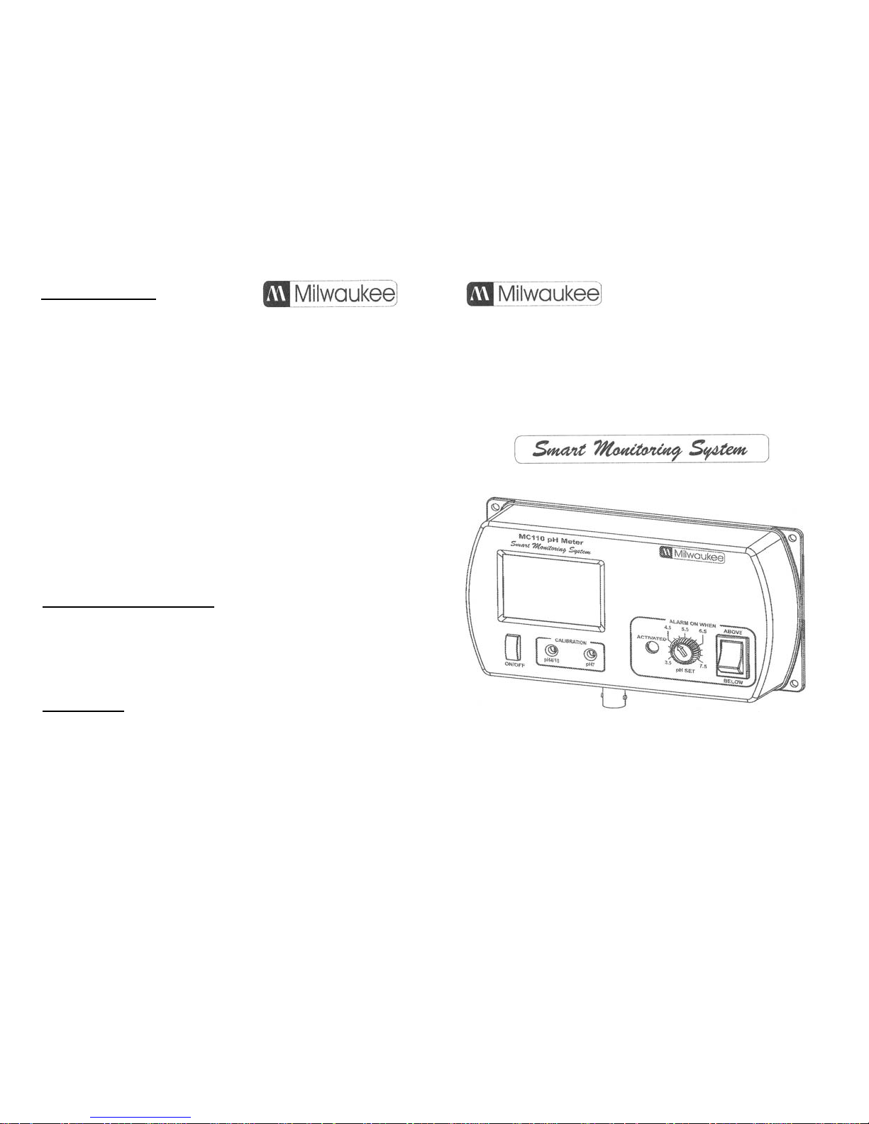
MANUAL
PORTABLE pH METER
MODELS:
MC110 - MC120 - MC122
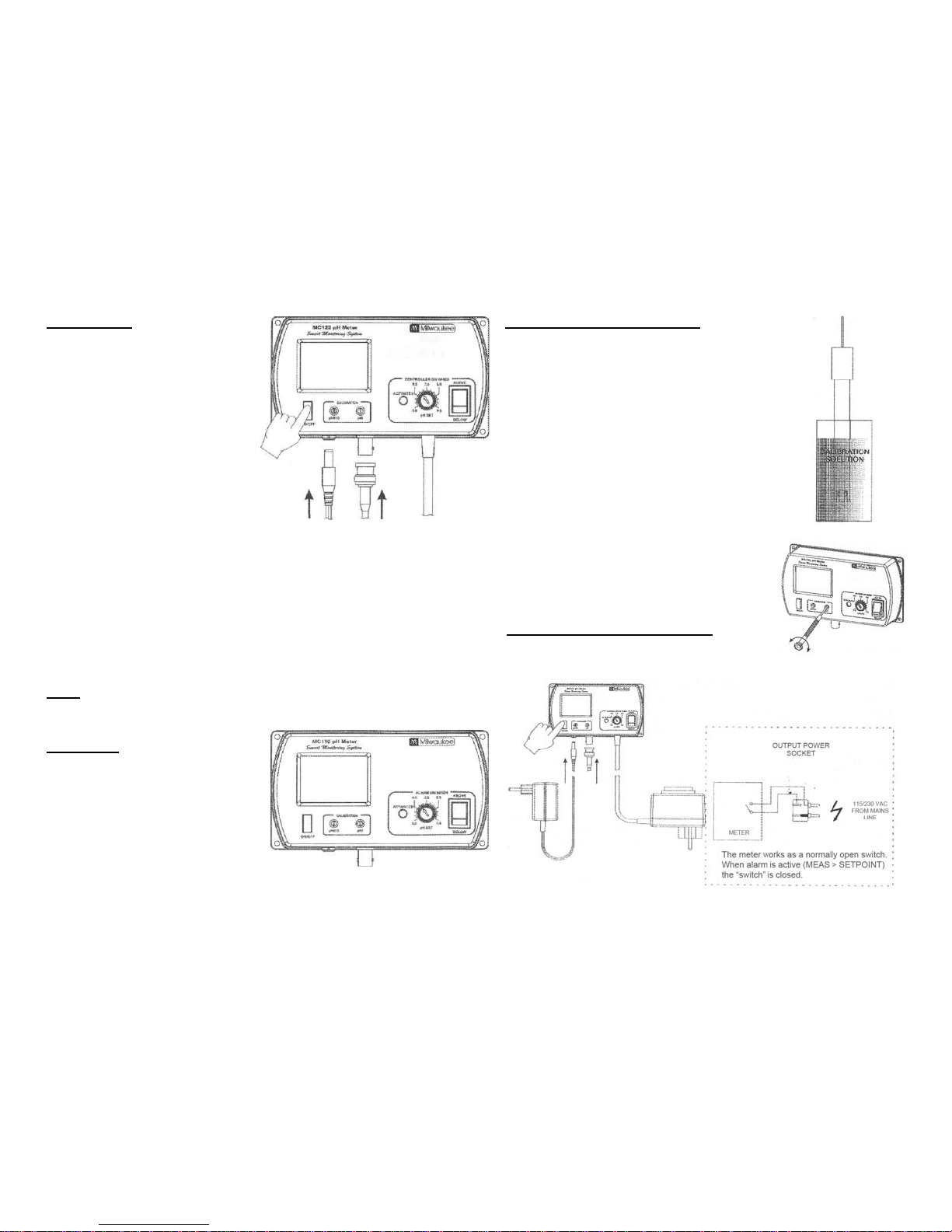
OPERATION
• Connect the supplied 12VDC pow er
adapter to the meter and to the
mains line.
:
• Connect the pH-electrode to the
BNC socket on the bottom of the
meter.
• Always remove the electrode
protective cap before taking any
measurem ent. If t he electrod e has
been left dry, soak the ti p (bottom
2.5 cm) in M10000 B rinse so lution
for a few minutes to re activate it
12VDC
O" RELAY OUTPUT
12VDC pH RELAY
ADAPTER ELECTRODE OUTPUT
• Make sure that the meter has been calibrated before taking any
measurements (see Calibration Proced ure).
• Immerse th e ti p (2.5 cm) of the pH-electrode into the sample.
• Turn the instrument on by pressing the ON/OFF key.
• Allow the reading to stabilize and the meter will start continuous
monitoring.
• A blinking alar m w ill indi cate when the measured pH value is higher or
lower than selected setpoint, depending on user selection.
NOTE. The output power contact (MC122 only) has no protection fuse
inside the meter. It is recommended to protected it outside, against
failure.
SETPOINT
The setpoint can be selected by
adjusting the central front knob to the
desired value.
:
• The selectable range is from 3.5 to
7.5 pH for MC 110; from 5.5 to 9.5 pH
for MC120 and MC122.
• The nature of the setpoint can be
selected by setting the switch to the
desired position (ABOVE or BELOW).
CALIBRATION PROCEDURE
• Remove the protective cap from the electrode.
:
• Immerse t he elect rode t ip int o a new sach et of pH 7
calibration solution and allow the reading to stabilize.
• Adjust the pH7 calibration trimmer (on the front) to
display "7.0 pH".
• Open a new sachet of pH 4 calibration solution and
use a smal l quantity t o rinse the electrode.
• Immerse t he electro de tip into th e pH 4 sachet an d
allow the reading to stabilize.
• Adjust the pH4/10 calibration trimmer (on the front) to
display "4.0 pH".
• The calibration is now complete and the meter is
ready to take measurements.
• It is suggested to recalibrate the meter at least
once a month, after a prolonged stocking time
and after pH-electrode replacement.
INSTALLA TION PROCEDURE
(for MC122 only)
:
 Loading...