

Page 1
MAP-IS Rev. A 03/18
Table of Contents:
Section Page
1.0 IMPORTANT RECEIVING INSTRUCTIONS . . . . . .1
2.0 SAFETY . . . . . . . . . . . . . . . . . . . . . . . . . . . . . . . . .1
3.0 PRODUCT DESCRIPTION . . . . . . . . . . . . . . . . . . .4
4.0 PRODUCT DATA . . . . . . . . . . . . . . . . . . . . . . . . . . .4
5.0 INSTALLATION AND SETUP . . . . . . . . . . . . . . . . .6
6.0 OPERATION . . . . . . . . . . . . . . . . . . . . . . . . . . . . . .8
7.0 INSPECTION, MAINTENANCE & STORAGE . . . . .9
8.0 ROUTINE MAINTENANCE PROCEDURES . . . . . .9
Instructions Sheet
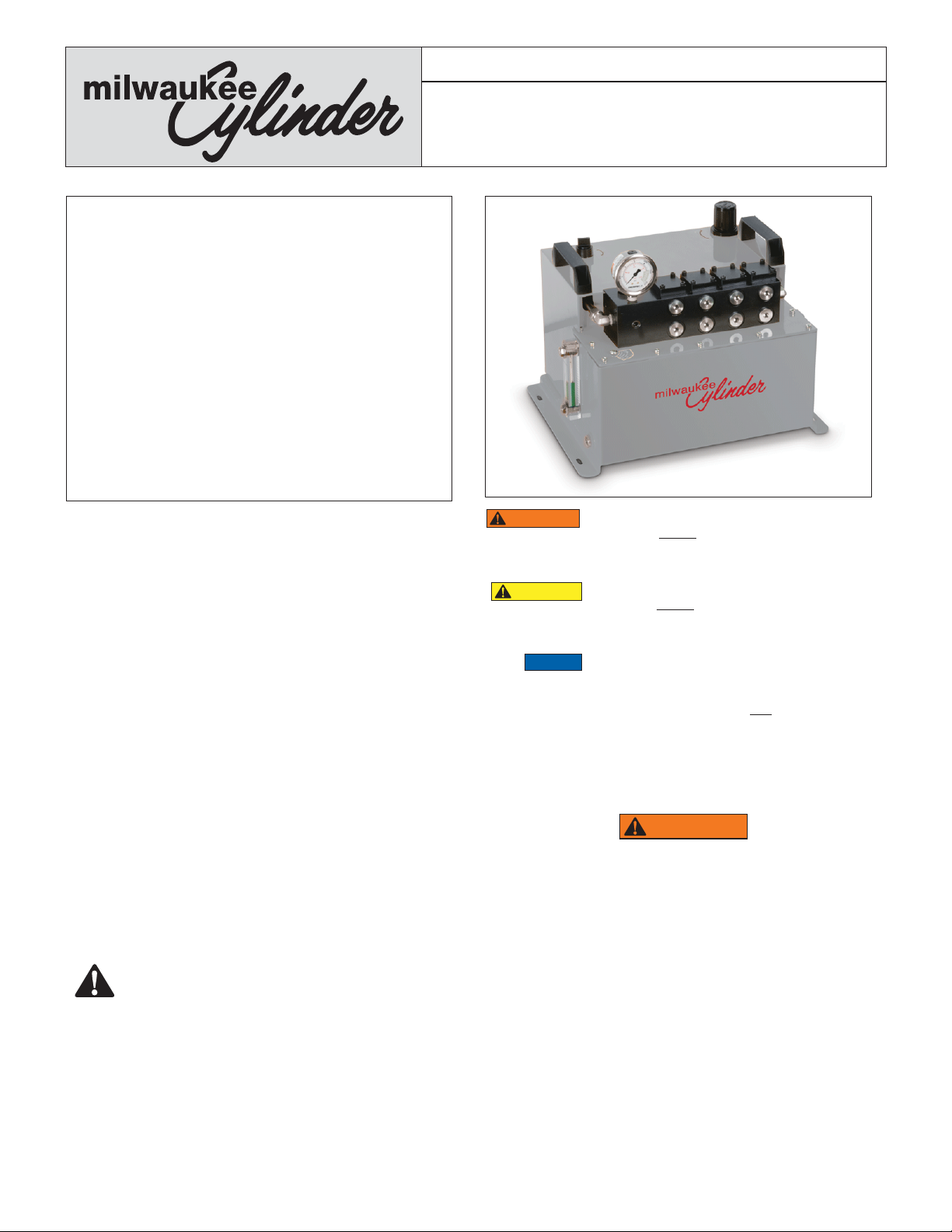
Milwaukee Cylinder DuroTech™ Series
Air-Driven Hydraulic Pumps
MAP07, MAP15 and MAP30*
9.0 TROUBLESHOOTING . . . . . . . . . . . . . . . . . . . . .14
*MAP30 available as a special only. Please contact Milwaukee
Cylinder customer service for details.
1.0 IMPORTANT RECEIVING INSTRUCTIONS
Visually inspect all components for shipping damage. Shipping
damage is not covered by warranty. If shipping damage is found,
notify carrier at once. The carrier is responsible for all repair and
replacement costs resulting from damage in shipment.
2.0 SAFETY
2.1 Introduction
Read all instructions carefully. Follow all recommended safety
precautions to avoid personal injury as well as damage to the
product and/or damage to other property. Milwaukee Cylinder
cannot be responsible for any damage or injury from unsafe
use, lack of maintenance or incorrect operation. Do not remove
warning labels, tags, or decals. In the event any questions or
concerns arise, contact Milwaukee Cylinder customer service
representative.
This manual follows a system of safety alert symbols, signal
words and safety messages to warn the user of specifi c hazards.
Failure to comply with these warnings could result in death or
serious personal injury, as well as damage to the equipment or
other property.
The Safety Alert Symbol appears throughout this
manual. It is used to alert you to potential physical
injury hazards. Pay close attention to Safety Alert
Symbols and obey all safety messages that follow this symbol to
avoid the possibility of death or serious personal injury.
Safety Alert Symbols are used in conjunction with certain Signal
Words that call attention to safety messages or property damage
messages and designate a degree or level of hazard seriousness.
The Signal Words used in this manual are WARNING, CAUTION
and NOTICE.
WARNING
CAUTION
NOTICE
Indicates a hazardous situation that, if not
avoided, could result in death or serious
personal injury.
Indicates a hazardous situation that, if not
avoided, could result in minor or moderate
personal injury.
Indicates information considered important,
but not hazard related (e.g. messages relating
to property damage). Please note that the
Safety Alert Symbol will not be used with this
signal word.
2.2 Hydraulic Pump Safety Precautions
(DuroTech Series)
WARNING
Failure to observe and comply with the following precautions
could result in death or serious personal injury. Property
damage could also occur.
• Read and completely understand the safety precautions and
instructions in this manual before operating the pump or
preparing it for use. Always follow all safety precautions and
instructions, including those that are contained within the
procedures of this manual.
• Operating procedures will vary, depending on the system
arrangement and the specifi c components being used. Always
read, follow and completely understand all manufacturer's
instructions when operating cylinders, valves and any other
hydraulic devices used with the pump. Follow all safety
precautions contained in the manufacturer's manuals.
• Always wear appropriate personal protective equipment
(P.P.E.) when operating hydraulic equipment. Be sure to wear
eye protection, work gloves and protective clothing. Use
of additional P.P.E. safety items such as dust mask, non-
1
Page 2

skid safety shoes, hard hat, and hearing protection (used
as appropriate for the conditions) will reduce the chance of
personal injuries. The use of these items may also be required
by local regulations or laws.
• Do not handle pressurized hoses. Escaping oil under pressure
can penetrate the skin. If oil is injected under the skin, see a
doctor immediately.
• Do not pressurize disconnected couplers.
• Only use hydraulic cylinders in a coupled system. Never use
a cylinder with uncoupled couplers. If the cylinder becomes
extremely overloaded, components can fail catastrophically,
causing severe personal injury.
• The pump is equipped with a hydraulic safety relief valve that
is factory preset to the pump's maximum operating pressure.
DO NOT attempt to adjust, bypass or alter the safety relief
valve. This valve is not user-adjustable.
• The system operating pressure must not exceed the pressure
rating of the lowest rated component in the system. Refer to
Section 4.1 of this manual for the maximum rated working
pressure for your pump model.
• Install pressure gauge(s) in the system to monitor operating
pressure. It is your window to see what is happening in the
system.
• Never set the pump hydraulic pressure to a higher setting than
the maximum rating of the hoses and connected devices.
The pressure setting should not exceed the setting of the
lowest rated component (pump, cylinder or other hydraulic
component) in the circuit.
• Do not exceed equipment ratings. Overloading may cause
equipment failure and possible personal injury.
• Always perform a visual inspection of the pump before placing
it into operation. If any problems are found, do not use the
pump. Have the pump repaired and tested before it is returned
to service.
• Fill the pump reservoir with hydraulic oil only to the
recommended level. Fill only when cylinders (or other hydraulic
actuators) are in their normal de-energized position.
• Never use the pump if it is leaking oil. Do not use the pump if it
is damaged, has been altered or is in need of repair.
• Always lift the pump using only the provided lifting handles.
• Allow only trained and experienced personnel to operate the
pump.
• Be certain that hydraulic pressure is fully relieved from the
cylinder (or other hydraulic actuator) before disconnecting
hydraulic hoses, loosening hydraulic fi ttings, or performing
any disassembly or repair procedures.
• If hydraulic equipment is damaged, do not touch or go near
any area where high-pressure oil is spraying. Promptly stop
usage of the hydraulic equipment and replace the damaged
parts with new ones before using the equipment again.
• Do not put your hands or body in line with the face of a
disconnected coupler. If the coupler becomes pressurized and
leakage occurs, the high-pressure oil stream could penetrate
the skin.
• Skin penetration from high-pressure hydraulic oil can result in
death or serious personal injury. If oil is injected under the skin,
see a doctor immediately.
CAUTION
Failure to observe and comply with the following precautions
could result in minor or moderate personal injury. Property
damage could also occur.
• Be careful to avoid damaging hydraulic hoses. Avoid sharp
bends and kinks when routing hydraulic hoses. Do not
exceed the minimum bend radius specifi ed by the hose
manufacturer. Using a bent or kinked hose will cause severe
back-pressure. Sharp bends and kinks will internally damage
the hose, leading to premature hose failure.
• Do not drop heavy objects on hoses. A sharp impact may
cause internal damage to hose wire strands. Applying
pressure to a damaged hose may cause it to rupture.
• Do not lift hydraulic equipment by the hoses or couplers.
• Make sure that all system components are protected from
external sources of damage, such as moving machine parts,
sharp edges and corrosive chemicals.
• Keep hydraulic equipment away from fl ames. Flames near
a hydraulic oil leak could cause the hydraulic oil to ignite,
resulting in a fi re.
• For optimum performance, do not expose hydraulic
equipment to temperatures of 150˚F [65˚C] or higher.
Excessive heat will soften packings and seals, resulting in
possible hydraulic fl uid leaks.
• Protect all hydraulic equipment from weld spatter.
• Protect the pump against rain, mud, dust, and humidity
when using it outdoors.
• Disconnect air supply hose when pump is not in use for
a prolonged period of time. NEVER remove a swivel air
connector while the air hose is pressurized.
• Immediately replace worn or damaged parts with genuine
Milwaukee Cylinder parts. Milwaukee Cylinder parts are
designed to fi t properly and to withstand high loads. NonMilwaukee Cylinder parts may break or cause the product
to malfunction.
NOTICE
• Hydraulic equipment must only be serviced by a qualifi ed
hydraulic technician. For repair service, contact Milwaukee
Cylinder customer service representative.
• To help ensure proper operation and best performance, use
only genuine Enerpac hydraulic oil.
2.3 Additional Safety References
Consult the applicable industry and/or government standards
in your country or region for additional safety precautions and
work rules applicable to hydraulic pumps, hydraulic devices
and related components.
3.0 PRODUCT DESCRIPTION
The Milwaukee Cylinder DuroTech Series Air Driven Hydraulic
Pump is intended for high-use, high-fl ow industrial applications.
Three di erent maximum pressure ratings are available to suit
a wide variety of user requirements.
Each valve manifold contains four stations, allowing for up to
four control valves to be installed. Control valves are available
from Milwaukee Cylinder or Enerpac (sold separately).
The dual action pump element combines smooth operation
with maximum durability. A built in air fi lter/regulator allows
easy adjustment of pump hydraulic pressure and helps protect
the pump air components from containments.
The large 1.8 gallon [6.8 liter] hydraulic reservoir provides
ample oil capacity to power multiple hydraulic devices.
A removable metal shroud allows easy access to the pump
element for routine inspection and maintenance activities.
2
Page 3
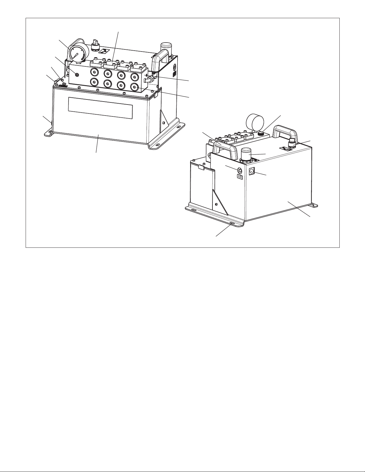
2
1
9
8
7
B
A
6
Key:
1. Hyd. Pressure Gauge
5
2. Cover Plate/Valve Station
3. Hyd. Manifold
4. Hyd. Hose Ports
5. Hyd. Reservoir
6. Drain Plug
7. Sight Gauge
8. Vent Screw
9. Hyd. Pressure
Sensor Port
B
B
A
B
A
A
10. Carrying Handle
11. Hyd. Oil Fill Plug
12. Air On-O Control
13. Metal Shroud
14. Mounting Hole
15. Air Pressure Gauge
16. Air Pressure Control
17. Air Inlet Connection
3
4
11
10
12
16
17
15
13
14
Figure 1 - Major Features and Components
3
Page 4
4.0 PRODUCT DATA
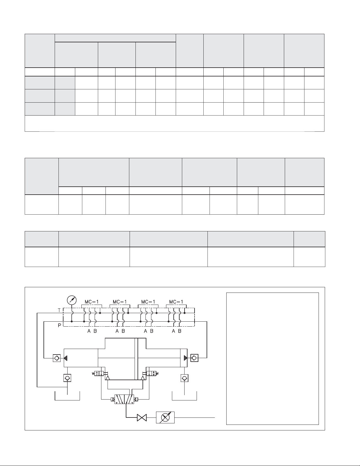
4.1 Specifi cations, Pressure, Flow and Air Consumption
Hydraulic Pressure
Pump
Series
MAP07 1920 132 1595 110 2000 138 16:1 612 10.0 30-120 2.0-8.2 24 0.68
MAP15 2760 190 2320 160 3000 207 23:1 465 7.6 30-120 2.0-8.2 24 0.68
MAP30 5280 364 4785 330 5500 379 48:1 252 4.1 30-110 2.0-7.6 20 0.57
1) Based on 120 psi [8.3 bar] air pressure for the MAP07 and MAP15 Series, and 110 psi [7.6 bar] air pressure for the MAP30 Series.
2) At zero (0) psi/bar hydraulic pressure.
Max. Hyd.
Working
Pressure
psi bar psi bar psi bar - in
1)
Max. Hyd.
Pressure
@100 psi Air
[6.9 bar]
2)
Hyd. Safety
Relief Valve
Setting
Pressure
Ratio
Hydraulic
to Air
Max. Hydraulic
Flow
@100 psi Air
[6.9 bar]
3
/min l /min psi bar scfm m³/min
2)
Air Pressure
Range
Max Air
Consumption
@ 100 psi Air
[6.9 bar]
4.2 Additional Specifi cations
Pump Series
MAP07
MAP15
MAP30
Reservoir Usable
Oil Capacity
Gallons in
1.8 415 6.8
3
Approximate Weight
Hydraulic Oil
Liters Type lb kg °C °F dBA
Enerpac HF
(Refer to Section 5.3)
(not including
hydraulic oil or
control valves)
71 32.2 0 to 60 32 to 150 75
Operating
Temperature
Range
Sound Level
Pump Series Air inlet connection Hydraulic Hose Connection Hydraulic Valve Manifold Station
MAP07
MAP15
MAP30
1/4" NPT #8 SAE D03 4
4.3 Schematic Diagram
Description of Operation:
Air is automatically ported and
vented to the pump piston.
The piston plunger contains a
pressurizing ram at each end. Every
time the piston moves, one of the
rams sends pressurized hydraulic oil
to the manifold.
Shop air is connected to the builtin pressure regulator, allowing the
operator to adjust the air pressure,
that in turn sets the maximum
hydraulic oil pressure.
The air is ported through a builtin shut-o valve. With the shut-o
valve open, the pump automatically
starts and stops to obtain and then
maintain the customer selected
pressure.
Number of
Stations
4
Page 5
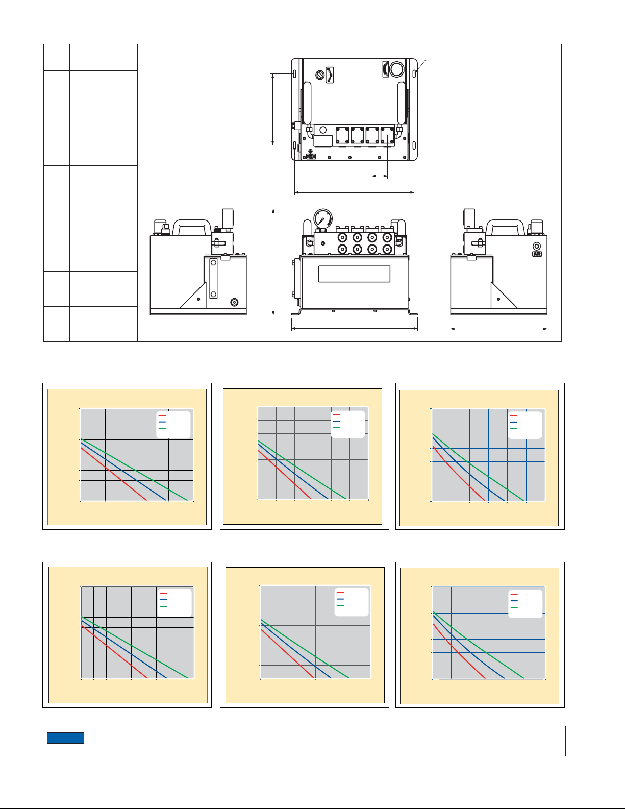
4.4 Pump Dimensions
u
Item inch mm
A 8.9 226
ø 0.31
B
x
0.09
C 2.0 51
D 15.8 401
E 13.2 335.2
F 16.6 421.6
G 12.7 332.6
7.9
x
2.3
B
A
C
D
BABABAB
A
E
F
G
4.5 Performance Curves (hydraulic pressure vs. fl ow)
Imperial
900
800
700
600
/min) X
3
500
400
300
Oil flow (in
200
100
0
0 200 400 600 800 1000 1200 1400 1600 1800
Hydraulic Pressure (psi)
60 psi
80 psi
100 psi
Air pressure
X
700
600
500
/min) X
400
3
300
200
Oil flow (in
100
0
0 500 1000 1500 2000 2500 3000
Hydraulic Pressure (psi)
60 psi
80 psi
100 psi
Air pressure
X
MAP07 Series MAP15 Series MAP30 Series
350
300
250
/min) X
200
3
150
100
Oil flow (in
50
0
0 1000 2000 3000 4000 5000 6000
Hydraulic Pressure (psi)
Metric
14.8
13.1
11.5
9.8
8.2
6.6
4.9
Oil flow (l/min) X
3.3
1.6
0
0 14 28 41 55 69 83 97 110 124
Hydraulic Pressure (bar)
4.1 bar
5.5 bar
6.9 bar
Air pressure
X
11.5
9.8
8.2
6.6
4.9
3.3
Oil flow (l/min) X
1.6
0 34 69 103 138 172 207
Hydraulic Pressure (bar)
4.1 bar
5.5 bar
6.9 bar
Air pressure
X
5.7
4.9
4.1
3.3
2.5
1.6
Oil flow (l/min) X
0.8
0
0 69 138 207 276 345 414
Hydraulic Pressure (bar)
WAP07-Hydra
60 psi
80 psi
100 psi
Air pressure
X
4.1 bar
5.5 bar
6.9 bar
Air pressure
X
MAP07 Series MAP15 Series MAP30 Series
NOTICE
Performance will be signifi cantly diminished if air pressure falls below 50 psi [3.4 bar]. Actual performance may vary
from values shown, due to seal friction, internal pressure drops and manufacturing tolerances.
5
Page 6
5.0 INSTALLATION AND SETUP
5.1 Mounting
Install the pump on a solid and level horizontal surface that is
capable of supporting the weight of the pump, control valves and
any associated equipment.
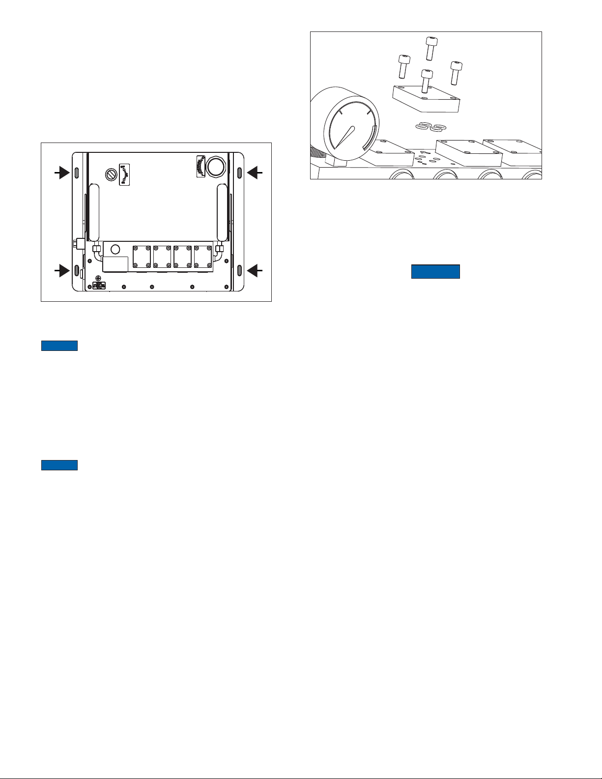
Four slotted mounting holes are provided on the
pump bottom fl ange. See Figure 2. Secure the pump
with 5/16" SAE or M8 ISO screws (user supplied).
Figure 2 - Mounting Holes
NOTICE
(with the pump bottom fl ange facing down). To avoid damage to
pump and possible oil leakage, do not attempt to mount the pump
on a wall or other vertical surface.
Pump must be operated only in the horizontal position
5.2 Valve Installation
Control valves are sold separately and are not included with the
pump. Refer to the Milwaukee Cylinder website or catalog for a
description of available control valves and related accessories.
Consult Milwaukee Cylinder if additional valve selection guidance
is needed.
NOTICE
Milwaukee Cylinder DuroTech Series pumps.
When installing control valves, always work in a clean and dry
area. Take all appropriate precautions to avoid contamination and
dirt entry. Follow the valve manufacturer's instructions carefully to
ensure proper installation. Be sure that the cover plates remain tightly
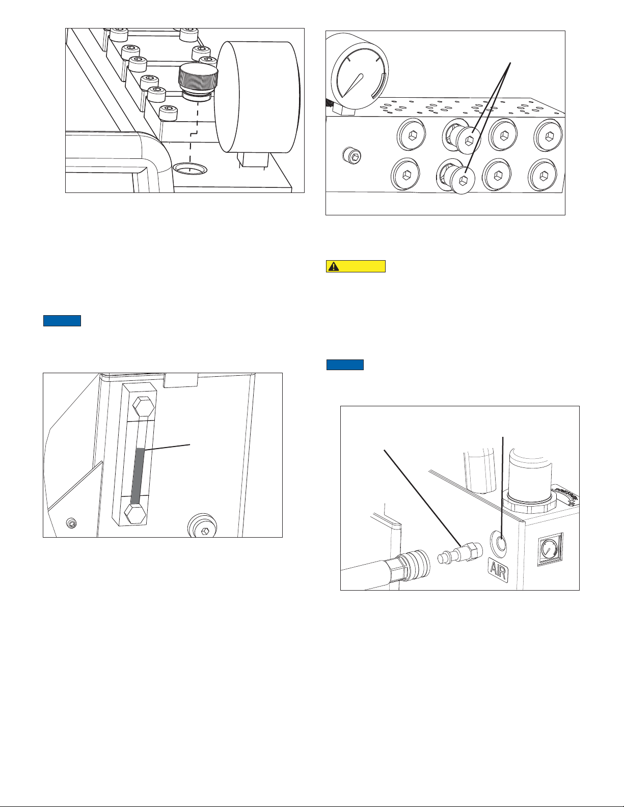
installed over all unused valve stations. See Figure 3.
The Milwaukee Cylinder cross over cover plate (optional
accessory) can be used to covert A and B outlet ports to P and T
ports for use with remote mounted valves.
Tandem center control valves should not be used with
Figure 3 - Control Valve Mounting Station
and Cover Plate (D03 Manifold Shown)
5.3 Hydraulic Reservoir
The pump is shipped without oil. Reservoir must be fi lled with oil
before pump is operated.
Use only a high quality ISO 32 grade hydraulic oil recommended.
NOTICE
• Failure to use the correct oil type (high-quality ISO 32 hydraulic
oil) may result in damage to pump hydraulic components and
will void the product warranty.
• Be sure that the oil is clean. The oil cleanliness should be
maintained to a maximum level of 18/16/13 per the ISO
4406 standard. If the oil develops a milky, cloudy or dark
appearance, it should be changed immediately.
• To avoid overfi lling and possible equipment damage, add
oil to the pump reservoir only after all connected hydraulic
devices are de-energized and system pressure is completely
relieved.
Add oil as described in the following steps:
1. Be certain that the air shut-o valve is in the OFF position
2. Verify that the pump hydraulic pressure gauge and pump
air pressure gauge both read zero (0) psi/bar.
3. Be sure that all connected hydraulic devices are fully de-
pressurized.
4. Loosen the vent screw one full turn to provide reservoir
venting.
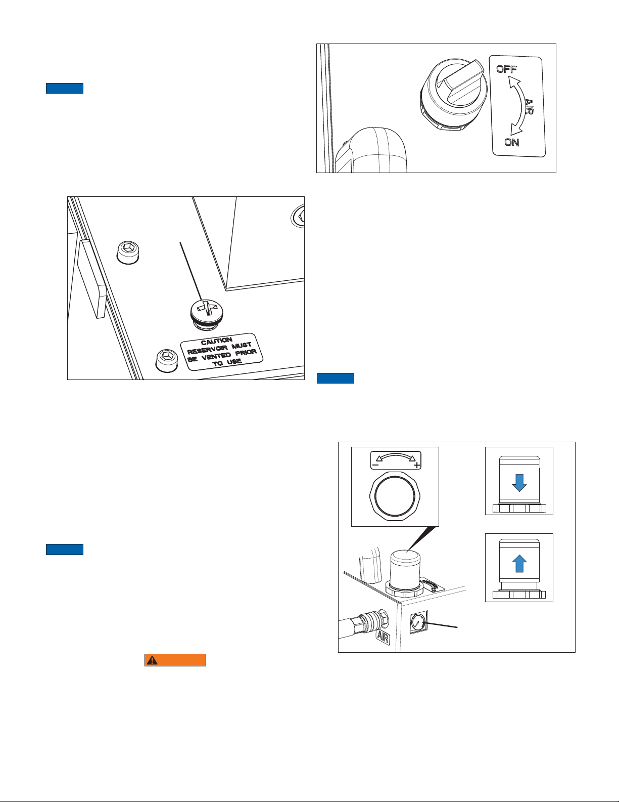
5. Loosen and remove the oil fi ll plug. See Figure 4.
6. Slowly pour oil through the oil fi ll port while watching the
level in the reservoir sight gauge. Stop pouring when the
reservoir is 1/2 to 3/4 full. DO NOT OVERFILL. Refer to
Section 5.4 for additional information.
7. Reinstall the oil fi ll plug after adding oil. Tighten oil fi ll plug
snug tight.
6
Page 7
Refer to Section 4.2 for port
type and thread size.
Figure 4 - Oil Fill Plug
5.4 Oil Level
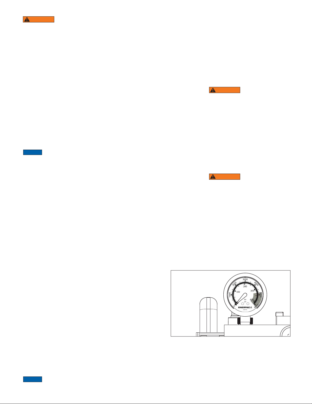
The oil level sight gauge is located on the left-hand side of the
pump,
The reservoir should be 1/2 to 3/4 full with all cylinders or other
hydraulic actuators fully retracted. See Figure 5.
Never allow the oil level to rise above the top (high) line or fall
below the bottom (low) line.
NOTICE
OFF position and the hydraulic system fully depressurized. Be
certain that all hydraulic actuators are fully retracted. Failure to
observe this instruction may result in the reservoir becoming
overfi lled.
Always check oil level with the air on-o control in the
Oil Level
B
A
B
A
B
A
B
A
Figure 6 - Hydraulic Connections
5.6 Air Requirements
CAUTION
ensure that the air on-o control is in the OFF position.
Failure to follow these directions may result in unintended
pump startup when air supply hose is connected.
To ensure optimum performance, the air source must be
capable of providing a constant supply of air at the required
pressure and fl ow rate for your pump model. Refer to Table 4.1
for additional information.
NOTICE
bar] static for MAP30 Series models. Supply air pressure
should not exceed 120 psi [8.2 bar] static for MAP07 and
MAP15 Series models.
Before connecting the air supply hose,
Supply air pressure should not exceed 110 psi [7.5
Air Inlet
Air coupler
1/4" NPT
(user-supplied)
Figure 5 - Oil Level Sight Gauge
Add oil if the oil level drops below 1/2 full. A small amount of
additional oil may need to be added to the reservoir after the
pump has been operated for the fi rst time.
5.5 Hydraulic Hose Connections
The advance and retract ports are located on the front of the
hydraulic manifold. See Figure 6. Note that the top ports are
labeled “B” and the bottom ports are labeled “A”.
Port type and thread size will vary, depending on pump model.
Refer to Section 4.2 of this manual for additional information.
All hoses, fi ttings and other hydraulic components in the circuit
must be rated at or above the pump maximum working pressure.
Refer to sections 4.1 and 6.2 of this manual for additional
maximum pressure information.
Figure 7 - Pump Air Inlet
Use only dry and fi ltered compressed air. Use of a water separator
is strongly recommended. Pump internal components are selflubricating. Lubricated air is permitted but NOT required.
The pump air inlet connection is a 1/4" NPT fi tting. See Figure 7.
A suitable male air coupler (user supplied) must be installed
between the pump air inlet connection and the air supply line
or hose. Use PTFE sealing tape (or other suitable pipe sealant)
on the threads and torque to 7.4-11.0 ft-lb [10-15 Nm].
To ensure su cient air fl ow, the inside diameter of the air
supply hose or line must be not less than 0.39 inch [10 mm].
7
Page 8
5.7 Venting
A vent screw is located on the pump reservoir. Before using the
pump, loosen the vent screw one full turn to open the vent. See
Figure 8.
NOTICE
Reservoir must be vented during pump operation.
Failure to open the vent may result in cavitation and damage to
pump components.
The vent should also be opened before adding oil to the reservoir.
This will allow the oil to fl ow more easily into the tank.
The vent should be fully closed during sustained periods of
inactivity or whenever the pump is stored. When closing the vent,
tighten the vent screw snug tight, so that the underside of the
screw head only slightly compresses the O-ring seat.
Vent Screw
Figure 8 - Vent Screw
5.8 Air On-O Control
The pump air on-o control operates as follows:
all positions several times to relieve any residual pressure.
Figure 9 - Air On-Off Control
5.9 Air Pressure Adjustment
Adjustment of the pump air pressure setting results in a
corresponding change to the pump hydraulic pressure setting.
Adjust the pressure setting as described in the following steps:
1. Move the air on-o control to the OFF position.
2. Connect the air supply hose to the pump air inlet connection.
3. Pull up the air pressure adjustment knob. See Figure 10.
4. Turn the air pressure adjustment knob slowly counterclockwise
until the pump air pressure gauge indicates about 43.5 psi [3
bar].
5. While watching the pump air pressure gauge, slowly rotate
the air pressure adjustment knob clockwise until the gauge
indicates the air pressure setting that corresponds with the
hydraulic pressure setting required for your application.
NOTICE
on pump model. Refer to the ratios listed in the table in Section
4.1 and to the pressure-fl ow graphs in Section 4.5.
6. To prevent unexpected actuator operation from occurring in
The hydraulic-to-air pressure ratio varies, depending
the next step, be sure that all control valves are in the neutral
position.
ON position:
• Air from the plant air supply is directed to the pump pneumatic
circuit, activating the pump element. Hydraulic pressure will
start building immediately, and will be indicated on the pump
hydraulic pressure gauge.
• Pump will stop automatically when the user-adjustable pressure
setting is reached. Refer to Section 6.1 for additional details.
NOTICE
The user-adjustable pressure setting must be adjusted
before the pump is placed into operation. Refer to directions in
Section 5.9.
OFF position:
• Air from the plant air supply to the pump pneumatic circuit is
blocked (shut-o ).
• Some residual air pressure may still be present in the pump
pneumatic circuit.
WARNING
Air downstream of the air on-o control is NOT vented when
the OFF position is selected. Residual air pressure may be
present downstream of the control. Movement of hydraulic
actuators could occur when control valves are shifted, even
when the air on-o control is in the OFF position.
To prevent possible injury, stay clear of hydraulic actuators
until all pressure is completely relieved. With the air on-o
control in the OFF position, shift the control valve(s) through
LOCKED
ADJUSTMENT
KNOB
UNLOCKED
Air Pressure Gauge
Figure 10 - Air Pressure Adjustment Knob
and Pressure Gauge
7. Move the pump air on-o control to the ON position.
8. Check the pump hydraulic pressure gauge. If necessary,
readjust the air pressure up or down as required, until the
corresponding hydraulic pressure setting is correct for your
application.
8
Page 9
WARNING
hydraulic pressure gauge must not exceed the maximum
rating of the lowest rated hydraulic component in the circuit.
Failure to observe this instruction may result in catastrophic
failure, high pressure oil leakage and/or skin penetration.
Serious personal injury or death could result.
9. After confi rming the proper setting, press down on the air
adjustment knob to lock the setting.
The pressure reading shown on the pump
5.10 Air Removal
Trapped air must be removed from the hydraulic cylinder(s) and
hoses before the pump is placed into operation.
1. Move the air on-o control to the ON position.
2. Under no load, repeatedly cycle the cylinders (or other
hydraulic actuators) from the fully extended to fully retracted
position until operation is smooth. Repeat this procedure for
each valve station.
Smooth operation indicates that air has successfully been
removed from the system.
3. Move the air on-o control to the OFF position.
4. Check the oil level in the pump hydraulic reservoir. If oil level
has dropped, add additional oil to the reservoir as required.
NOTICE
requirements and reservoir fi lling instructions.
5. Check the air pressure setting after performing air removal
Refer to Section 5.3 of this manual for hydraulic oil
procedures. The air pressure setting (and the corresponding
hydraulic pressure setting) may drop slightly after the pump
has been operated for the fi rst time. If readjustment is
required, refer to the instructions in Section 5.9.
6.0 OPERATION
Specifi c pump operation procedures will vary, depending on
control valve type and confi guration, workholding devices
used and other factors. For detailed operating instructions and
related information, refer to the instruction sheet included with
your hydraulic valve(s), cylinder(s) or other actuator(s). Refer to
Section 6.1 for a general overview of pump operation. Also follow
the additional instructions and precautions contained in sections
6.2 and 6.3 of this manual.
6.1 Overview of Operation
Typical operation - with standard closed center or fl oat center
control valves (pressure holding type):
• The pump will start immediately if the air on-o control is
moved to the ON position while the control valve is in the
neutral position. The pump will stop automatically (and remain
idle) when pressure reaches the user-adjustable pressure
setting.
• If the pump is idle, and the control valve is moved from the
neutral position to either the advance or retract position, the
pump will start immediately. The pump will stop automatically
when pressure reaches the user-adjustable pressure setting.
Typical operation - with spool type closed center or fl oat center
control valves (non-sealed type):
• When the air on-o control is in the ON position and the control
valve is in the neutral position: The pump will start and stop as
needed to maintain the user-adjusted pressure. This feature
helps compensate for the normal internal oil leakage present
in a spool type control valve.
• Operation is otherwise the same as described for the standard
(pressure holding type) control valves.
NOTICE
It is mandatory that the operator has a full understanding
of all instructions, safety precautions and applicable safety
regulations before operating any high force hydraulic equipment.
If any questions or concerns, contact Milwaukee Cylinder
customer service representative.
6.2 Maximum Hydraulic Working Pressure
Rated maximum hydraulic working pressure varies, depending
on the pump model:
• MAP07 Series: 1920 psi [132 bar].
• MAP15 Series: 2760 psi [190 bar].
• MAP30 Series: 5280 psi [364 bar].
WARNING
Maximum hydraulic system pressure is limited by an internal
safety relief valve that is set slightly higher than the pump's
maximum rated hydraulic working pressure. Do not attempt
to adjust, bypass or alter this valve. It is factory set and is not
user-adjustable.
Be certain that all hydraulic hoses, hydraulic cylinders and
any other connected hydraulic devices are rated at or above
the maximum hydraulic working pressure for your pump
model.
Serious personal injury or death could occur if these
instructions and precautions are not followed.
6.3 Relieving Pneumatic and Hydraulic Pressure
WARNING
Failure to observe the following instructions and precautions
could result in dangerous high pressure oil leakage and
possible skin penetration. Death or serious personal injury
could result.
Perform the following procedure before disconnecting any
hydraulic hoses or lines from either the pump manifold or a
connected device, before loosening any hydraulic fi ttings or
before servicing the pump or any connected devices:
1. Move the pump air on-off control to the OFF position. See Figure 9.
2. Disconnect the air supply hose from the pump air inlet
connection. Be certain that the pump air pressure gauge
indicates zero (0) psi/bar. See Figure 10.
3. Cycle the hydraulic control valve(s) to relieve residual
pressure in the pump hydraulic system (this will also remove
residual pressure in the pump pneumatic system).
Figure 11 - Pump Hydraulic Pressure Gauge
4. Verify that all hydraulic pressure is completely relieved:
- Check that the pump hydraulic pressure gauge indicates
zero (0) psi/bar. See Figure 11.
- Verify that other hydraulic pressure gauges in the system (if
present) also indicate zero (0) psi/bar.
9
Page 10
- Be sure that no hydraulic hoses are sti , which may indicate
trapped pressure.
5. If any hydraulic pressure remains, cycle the control valve(s)
again to relieve pressure. Then, re-check the hydraulic
pressure gauge(s) to be sure that no pressure is indicated.
7.0 INSPECTION, MAINTENANCE & STORAGE
• Periodically check the pump for loose hydraulic connections
leaks and obvious problems. Replace any damaged
components immediately.
• Monitor the pump oil temperature during operation. Do not
exceed oil temperatures above 150°F [65°C].
• Install dust caps and plugs on all hydraulic couplings after the
hydraulic hoses are disconnected from the pump.
• Keep the pump and all hydraulic components clean.
• Change the hydraulic oil at the recommended interval shown
in Section 8.2 of this manual. Change the oil immediately if
dirty, or if contamination is suspected.
• Store the pump in a clean, dry and secure location. Keep the
stored pump and hoses away from heat and direct sunlight.
• If repair parts are required, refer to the Milwaukee Cylinder
website (www.milwaukeecylinder.com) for the repair parts
sheet applicable to your pump model.
NOTICE
a qualifi ed hydraulic technician. For repair service, contact
Milwaukee Cylinder customer service representative.
Hydraulic equipment must only be serviced by
8.0 ROUTINE MAINTENANCE PROCEDURES
8.1 Preparation
Always perform the following steps before beginning any
maintenance or repair procedures contained in Section 8:
1. Disconnect the air supply hose and fully relieve pneumatic
and hydraulic pressure. Follow the steps in Section 6.3.
2. Disconnect hydraulic hoses from hydraulic manifold. Install
plugs in open ports.
3. Position the pump on a workbench or other substantial work
surface.
NOTICE
fi gure does NOT include the weight of the hydraulic oil or the control
valves. Actual weight will vary, depending on amount of oil in
reservoir and number of control valves installed on manifold.
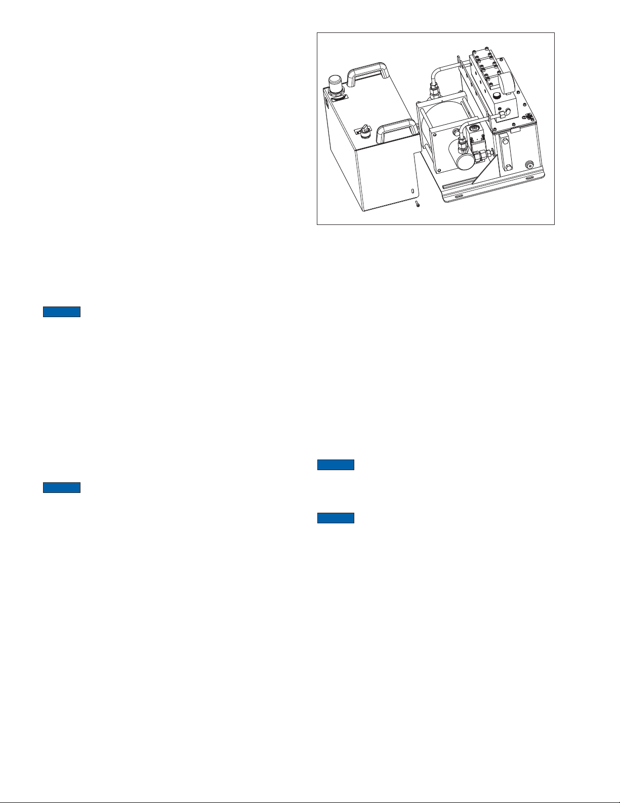
4. Remove the two screws located on either side of the pump
Pump dry weight is approximately 71 lb [32.2 Kg]. This
shroud. Remove the pump shroud and position it behind the
pump on the work surface. Be careful not to damage the
fl exible air tubing, which must remain connected. See Figure
12.
Figure 12 - Pump Shroud Removal
(Note: air tubing removed for illustrative purposes)
8.2 Oil Change
Change the hydraulic oil every 12 months. If the oil is dirty or
contaminated, change the oil immediately. Refer to the following
steps:
1. Fully relieve pressure in the pneumatic and hydraulic circuits.
Disconnect hoses. Refer to maintenance preparation
procedures in Section 8.1 of this manual. Also refer to
pressure relief procedures in section 6.3.
2. Place the pump on a workbench or other substantial work
surface. To allow draining in the next step, position the pump
so that the side with the oil drain plug is even with the edge
of the workbench.
3. Place a suitable container under the pump oil drain plug. The
container capacity must be 1.8 gallon [6.8 liter] or larger.
4. Slowly unscrew the oil drain plug and remove it. See Figure
13. Allow the old oil to fl ow into the container.
NOTICE
laws and regulations.
5. Clean and reinstall the oil drain plug.
6. Remove the oil fi ll plug. See Figure 4.
NOTICE
recommended. Refer to Section 5.3 for additional information.
7. Slowly pour new oil through the oil fi ll opening while watching
8. Reinstall the oil fi ll plug.
Dispose of used oil in accordance with all applicable
Use of Enerpac HF hydraulic oil is strongly
the oil sight gauge. Continue until reservoir is 1/2 to 3/4 full.
DO NOT OVERFILL.
10
Page 11
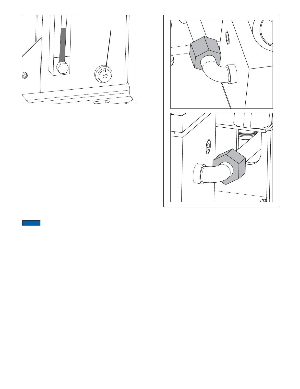
Drain Plug
Figure 13 - Drain Plug
9. Reconnect hoses and test pump operation without load
before placing the pump back into service. Cycle the
hydraulic cylinders (or other hydraulic actuators) until all air
is removed and operation is smooth.
8.3 Suction Strainer Replacement
Two suction strainer fi lters are located inside the pump oil
reservoir. Replace these strainers if there is a noticeable drop in
oil fl ow or if it is suspected that the oil is dirty or contaminated.
Refer to the following steps:
1. Fully relieve pressure in the pneumatic and hydraulic
circuits. Disconnect hoses. Remove pump shroud. Refer to
maintenance preparation procedures in Section 8.1 of this
manual. Also refer to pressure relief procedures in Section
6.3.
2. Place the pump on a workbench or other substantial work
surface.
3. Fully drain all oil from the hydraulic reservoir. Refer to the
steps in Section 8.2.
NOTICE
changed whenever the suction strainers are replaced.
4. Check that the pump hydraulic pressure gauge indicates
5. Loosen the connectors located on each end of the hydraulic
To ensure cleanliness, the hydraulic oil MUST be
zero (0) psi/bar. Hydraulic pressure must be completely
relieved before loosening hydraulic fi ttings in the following
step.
manifold. Refer to Figure 14.
Figure 14 - Connectors
(Located on each end of manifold)
11
Page 12
B
B
B
B
A
A
A
A
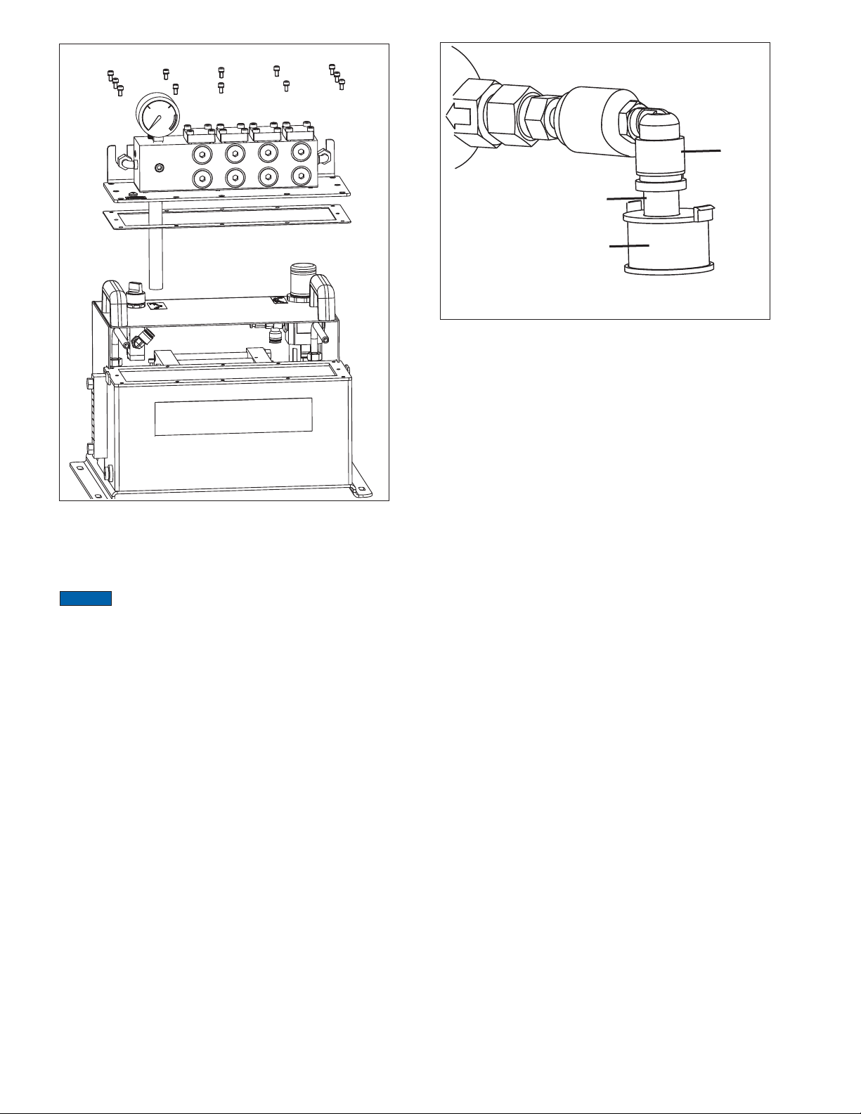
Figure 15 - Manifold Assembly
6. Remove the bolts and sealing washers securing the hydraulic
manifold and cover plate to the hydraulic reservoir. See
Figure 15.
NOTICE
Hydraulic manifold and cover plate assembly weighs
approximately 20 lb. [9 kg]. Manifold mounted control valves will
add additional weight.
7. Carefully lift the manifold and cover plate assembly straight
up until it is removed from the hydraulic reservoir. See Figure
15. Set this assembly aside, in a clean and dry location.
8. Install caps or plugs over all open fi ttings to prevent dirt
entry.
9. Inspect the hydraulic reservoir. Remove any sludge or debris
from the reservoir interior.
10. Unscrew and remove each oil suction strainer. Discard both
used suction strainers. See Figure 16.
1
2
Key:
1. Connector
2. Adapter
3. Suction Strainer
Figure 16 - Suction Strainer
11. Install two new oil suction strainers. Be sure that each new
suction strainer is oriented as shown in Figure 16. Hydraulic
fi ttings must be assembled so that fl at side of suction
strainer is parallel with reservoir fl oor. Refer to the pump
repair parts sheet for part number.
12. Clean the mating surfaces of the reservoir and the hydraulic
manifold cover plate.
13. Check the condition of the reservoir gasket. If the gasket is
worn or deteriorated, install a new reservoir gasket. Refer to
the pump repair parts sheet for part number.
14. Remove caps and plugs installed in step 8.
15. Carefully lift the manifold and cover plate assembly and
position it directly over the hydraulic reservoir opening. Note
the locating tabs on either side of the reservoir fl ange.
16. Slowly lower the assembly until the manifold cover plate is
supported by the hydraulic reservoir fl ange. Align bolt holes.
17. Apply PTFE pipe thread sealing tape to the threads of the
two hydraulic tubes. Engage threads of connectors and
hydraulic tubes. Tighten each connector until fi nger tight.
DO NOT fi nal tighten at this time.
18. Secure the manifold cover plate to the hydraulic reservoir
with twelve bolts and sealing washers. Torque each bolt to
20-22 in-lbs [2.26-2.49 Nm].
19. Tighten both connectors an additional 2-3 full turns beyond
fi nger tight.
20. Refi ll the hydraulic reservoir. Refer to the steps in Section
8.2 of this manual.
21. Reconnect hoses and test pump operation without load
before placing the pump back into service. Cycle the
hydraulic cylinders (or other hydraulic actuators) until all air
is removed and operation is smooth.
3
8.4 Air Filter/Regulator
The air fi lter/regulator contains a removable fi lter bowl and
cleanable air fi lter. Periodically check the fi lter bowl for
accumulated water and clean the fi lter. Refer to the following
procedure:
1. Fully relieve pressure in the pneumatic and hydraulic
circuits. Disconnect hoses. Remove pump shroud. Refer to
maintenance preparation procedures in Section 8.1 of this
manual. Also refer to pressure relief procedures in Section
6.3.
12
Page 13
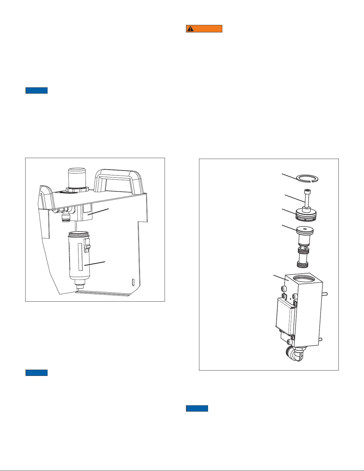
2. Locate the air fi lter/regulator. It is mounted inside the pump
shroud.
3. Grasp the fi lter bowl and depress the release button.
Pull straight down and remove the fi lter bowl from the air
regulator. See Figure 17.
4. Drain any accumulated water from the fi lter bowl. Remove
any dirt or debris. Wipe the fi lter bowl clean.
5. A fi lter element is located inside the air regulator housing.
Using a clean rag, wipe o any loose dirt or dust from the
fi lter element.
NOTICE
damaged, replace the entire fi lter/regulator. Replacement parts
are not available from Milwaukee Cylinder for this device. Order
complete fi lter/regulator unit. Refer to pump repair parts sheet
for fi lter/regulator part number.
6. Reinstall the fi lter bowl in the air regulator. Be sure it locks
7. Reconnect the air supply hose to the pump air inlet
If the fi lter element is very dirty, or if the fi lter bowl is
into place.
connection. Test pump operation without load before
placing the pump back into service.
the tapped center hole of the end cap.
WARNING
may be present under the end cap. End cap may eject
suddenly as it is being removed, even if the pump air pressure
gauge indicates zero (0) psi/bar. To prevent possible eye
injury, wear safety goggles during disassembly procedures.
3. Using a snap ring pliers, remove the snap ring.
4. Using a suitable needle nose pliers, grasp the head of the
M5 bolt. Pull straight up and remove the end cap from the
bore of the shuttle valve assembly.
5. Remove the M5 bolt from the end cap and reinstall it in the
tapped center hole of the piston.
6. Using a suitable needle nose pliers, grasp the head of the
M5 bolt. Pull straight up and remove the piston from the bore
of the shuttle valve assembly.
8.5.2 Inspection
1. Using a clean, lint free rag, remove the old grease lubricant
from piston, end cap, and from the valve assembly bore.
2. Inspect piston and end-cap for excessive wear, nicks,
scratches, corrosion or other problems.
A small amount of pressurized trapped air
1
Air Regulator
Filter Bowl
Figure 17 - Air Regulator and Filter Bowl
8.5 Air Shuttle Valve Routine Maintenance
The pump air shuttle valve is located on the right-hand side of
the pump element (when the pump is viewed from the rear).
The valve end cap and piston must be inspected, cleaned and
lubricated at the recommended time interval to ensure optimum
pump operation.
NOTICE
least every 100,000 cycles.
Refer to Figure 18 during the following procedures.
8.5.1 Disassembly
1. Fully relieve pressure in the pneumatic and hydraulic
2. To aid end cap removal, install an M5 bolt (user supplied) in
Disassemble and inspect the pump air shuttle valve at
circuits. Disconnect hoses. Remove pump shroud. Refer to
maintenance preparation procedures in Section 8.1 of this
manual. Also refer to pressure relief procedures in Section
6.3.
*
2
3
4
1. Snap Ring
2. End Cap
3. Piston
4. Housing
M5 Bolt
*
(user-supplied)
Figure 18 - Air Shuttle Valve Components
3. Check the condition of all piston seals. Replace entire piston
assembly if seals are worn or damaged.
NOTICE
entire air shuttle valve assembly. Individual components and
seals are not sold separately.
8.5.3 Reassembly
1. Using a small brush, lubricate the O-rings and seals on the
If obvious wear or damage is indicated, replace the
13
Page 14
piston with lithium grease.
2. If removed, re-install the M5 bolt in the tapped center hole of
the piston.
3. Align the piston with the bore opening and carefully reinstall
it in the bore.
4. Using a suitable needle nose pliers, apply fi rm pressure to
the head of the M5 bolt until the piston has bottomed out in
the bore of the housing. Then, unscrew and remove the M5
bolt.
5. Align the end cap with the bore opening and position it in the
bore.
6. Using a suitable needle nose pliers, apply fi rm pressure to
the end cap until it has bottomed-out, and is located just
below the snap ring groove.
7. Using a snap ring pliers, reinstall the snap ring.
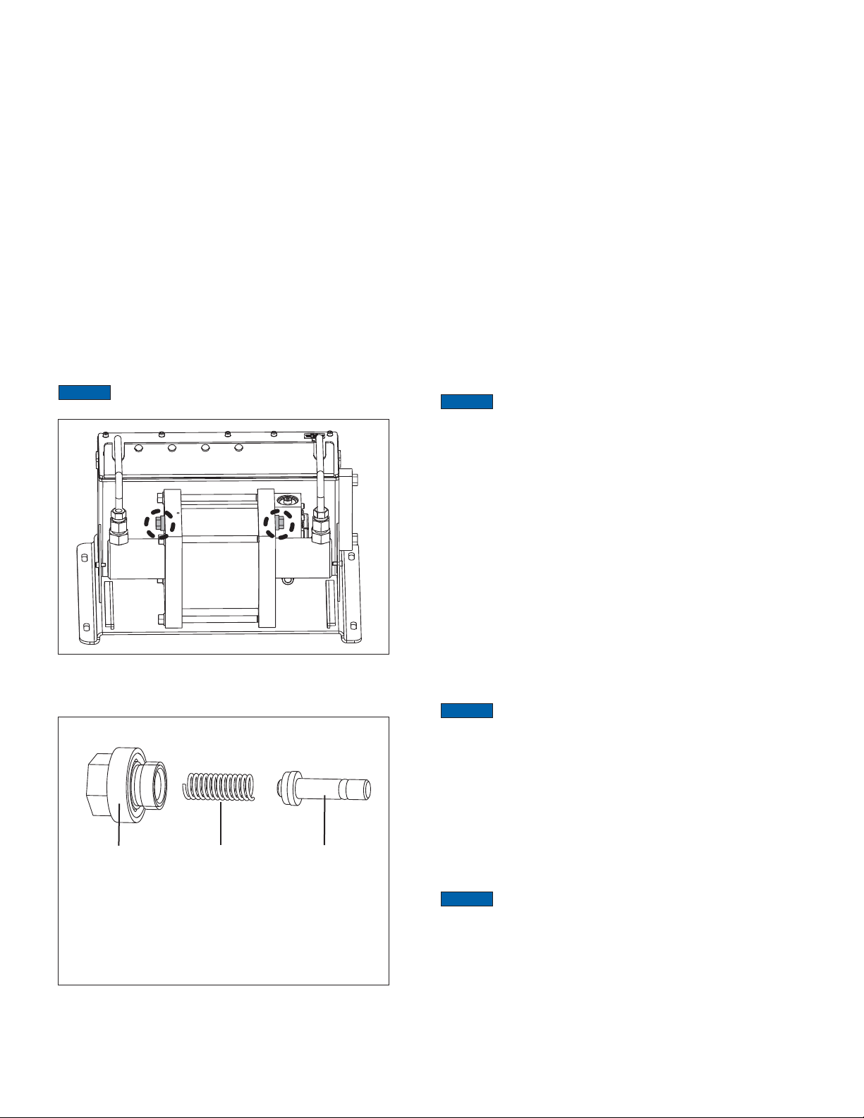
8.6 Pump Element Air Switch Maintenance
The pump element contains two air switches, one located
on each side of the pump element. The air switches must be
inspected, cleaned and lubricated at the recommended time
interval to ensure optimum pump performance.
NOTICE
least every 100,000 cycles.
Disassemble and inspect the pump air switches at
switch. Refer to Figures 19 and 20.
8.6.1 Disassembly
1. Fully relieve pressure in the pneumatic and hydraulic
circuits. Disconnect hoses. Remove pump shroud. Refer to
maintenance preparation procedures in Section 8.1 of this
manual. Also refer to pressure relief procedures in Section
6.3.
2. Using an adjustable wrench, loosen and remove the air
switch cap nut.
3. Using a right-angle needle nose pliers, grasp the end of the
air switch piston and carefully pull it straight out of the air
switch bore.
4. If it was not removed with the piston, remove the coil spring.
8.6.2 Inspection
1. Using a clean, lint free rag, remove old grease lubricant from
the air switch bore, the piston and the coil spring.
2. Inspect piston for obvious wear, nicks, scratches, corrosion
or other problems. Recondition or replace piston as required.
3. Check the condition of both piston seals. Replace entire
piston assembly if seals are worn or damaged.
NOTICE
entire air switch assembly. Individual components and seals are
not sold separately.
4. Inspect the coil spring. Replace if broken, bent or obviously
8.6.3 Reassembly
1. Using a small brush, lubricate the piston surface, O-rings
2. Place the coil spring around the piston.
3. Carefully place the piston and coil spring into the air switch
4. Engage the threads on the cap nut with the threads in the air
If obvious wear or damage is indicated, replace the
worn. Refer to pump repair parts list for part number.
and seals with lithium grease.
bore.
switch bore. Using a wrench, tighten the end cap snug tight.
Figure 19 - Air Switches
(viewed with shroud removed)
1
Key:
1. Cap Nut
2. Coil Spring
3. Piston
Figure 20 - Air Switch - Exploded View
Always perform maintenance procedures for BOTH air switches.
Follow the instructions in sections 8.6.1 through 8.6.3 for each air
2
3
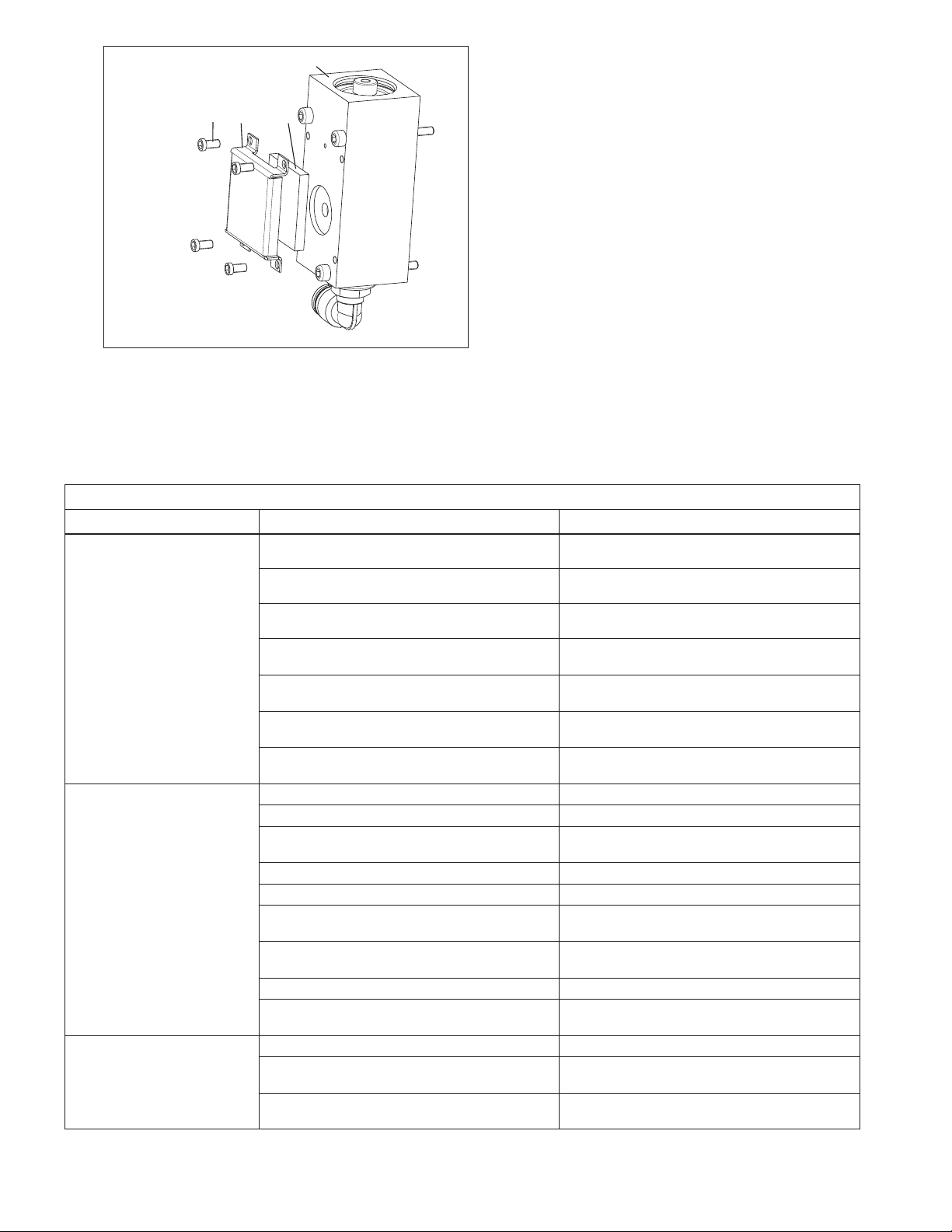
8.7 Air Exhaust Mu er
The pump air shuttle valve contains a mu er assembly. The
mu er felt must be replaced at the recommended time interval
to ensure optimum pump performance.
NOTICE
Replace the air exhaust mu er felt as described in the following
steps:
1. Fully relieve pressure in the pneumatic and hydraulic
2. Loosen and remove the four screws securing the cover to
3. Remove the cover. Remove and discard the old mu er felt.
NOTICE
Cylinder, but is available from many pneumatic maintenance
supply distributors.
4. Place the new mu er felt inside the cover.
5. Position the cover plate against the air shuttle valve and
Replace the mu er felt at least every 100,000 cycles.
circuits. Disconnect hoses. Remove pump shroud. Refer to
maintenance preparation procedures in Section 8.1 of this
manual. Also refer to pressure relief procedures in Section
6.3.
the air shuttle valve. See Figure 21.
Exhaust mu er felt is not purchasable from Milwaukee
secure it with four screws.
14
Page 15
4
9.0 TROUBLESHOOTING
Refer to the troubleshooting guide when diagnosing pump
operational problems. Please note that the troubleshooting guide
1
2
3
is not all-inclusive, and should be considered only as an aid to
help diagnose the most common possible problems.
For repair service, contact Milwaukee Cylinder customer service
representative. As required, also refer to the troubleshooting
information provided with your hydraulic control valves and other
system components.
Key:
1. Screw
2. Cover
3. Mu er Felt
4. Air Shuttle Valve
Figure 21 - Air Exhaust Muffler
TROUBLESHOOTING GUIDE
Problem Possible Cause Action
Pump does not cycle. No air pressure at supply. Check air supply.
Pump air-shuto valve closed. Open pump air-shuto valve.
Pump air pressure regulator set too low. Check pressure regulator setting.
Pump air exhaust mu er dirty. Clean or replace the mu er felt. Refer to Section 8.7
Pump air shuttle valve needs cleaning and
lubrication.
Pump air motor worn or damaged. Contact Milwaukee Cylinder customer service
Pump element jammed. Contact Milwaukee Cylinder customer service
Pump fails to build hydraulic
pressure or builds less than
desired pressure.
Pump Noise. Low air pressure or volume at air supply. Check air supply.
Low air pressure or volume at air supply. Check air supply.
Pump air pressure regulator set too low. Check regulator setting.
Pump air exhaust mu er dirty. Clean or replace the mu er felt. Refer to Section 8.7
Control valve returning oil to reservoir. Change position of control valve.
Low oil level in reservoir. Check oil level. Add oil as required.
Pump suction strainer elements dirty. Replace pump suction strainer elements. Refer to
Oil leakage at hydraulic hoses, fi ttings or connected
devices.
Internal leakage in control valve or valve manifold. Repair or replace components as required.
Internal leakage in pump element. Pump element
worn or damaged.
Pump air pressure regulator set too low. Check regulator setting. Refer to Section 5.9 of this
Pump air exhaust mu er dirty. Clean or replace the mu er felt. Refer to Section 8.7
(continued on next page)
of this manual.
Refer to procedure in Section 8.5 of this manual.
representative.
representative.
of this manual.
Section 8.3 of this manual.
Replace leaking components as required.
Contact Milwaukee Cylinder customer service
representative.
manual.
of this manual.
15
Page 16
TROUBLESHOOTING GUIDE (continued)
Problem Possible Cause Action
Oil leakage Loose connections. Tighten loose connections. Replace any worn or
Worn or damaged components. Repair or replace components as required.
Jerky or erratic pump operation. Low air pressure or volume at plant air supply. Check plant air supply.
Air in hydraulic lines. Remove air as described in Section 5.10 of this
Hydraulic oil dirty. Change hydraulic oil. Use Enerpac HF oil. Refer to
Low oil level in reservoir. Check oil level. Add oil as required. Refer to sections
Pump suction strainer elements dirty. Replace pump suction strainer elements. Refer to
Internal leakage in pump element. Pump element
worn or damaged.
Excessive moisture in pump
exhaust.
Air leakage. Loose air system connections. Tighten connections as required.
Excessive water and/or lubricant in supply air. Reduce moisture in air. Install water separator.
Pump air fi lter bowl needs draining. Check bowl for water. Drain as required. Refer to
Pump air fi lter dirty. Clean air fi lter element. Refer to Section 8.4 of this
Internal leakage in pump element. Pump element
damaged or worn.
damaged connectors.
manual.
Section 8.2 of this manual.
5.3 and 5.4 of this manual.
Section 8.3 of this manual.
Contact Milwaukee Cylinder customer service
representative.
Note: Pump components are self-lubricating.
Lubricated air is permitted, but not required.
Section 8.4 of this manual.
manual.
Contact Milwaukee Cylinder customer service
representative.
Worn or damaged air system components. Repair or replace components as required.
Cylinder drift. External system leak. Repair or replace leaking components as required.
Internal leak in system component. Repair or replace leaking components as required.
Low oil fl ow rate. Reservoir not vented. Open vent screw on reservoir. Refer to Section 5.7 of
Pump air fi lter bowl needs draining. Check bowl for water. Drain as required. Refer to
Pump air fi lter dirty. Clean air fi lter element. Refer to Section 8.4 of this
Internal leakage in pump element. Pump element
worn or damaged.
Low air pressure or volume at air supply. Check air supply.
Pump air pressure regulator set too low. Check regulator setting. Refer to Section 5.9 of this
Pump suction strainer elements dirty. Replace pump suction strainer elements. Refer to
Cylinder will not return. Return fl ow blocked or restricted. Check system for blockages and make repairs
Control valve malfunction. Repair or replace control valve as required.
this manual.
Section 8.4 of this manual.
manual.
Contact Milwaukee Cylinder customer service
representative.
manual.
Section 8.3 of this manual.
as required. Be sure that all couplers are fully
connected.
16
Page 17

Notes:
Page 18

Notes:
Page 19

Notes:
Page 20

https://www.milwaukeecylinder.com
 Loading...