

Milwaukee M4910-20 User Manual
OPERATOR’S MANUAL
TECHNICAL SUPPORT - SPARE PARTS 1.877.203.0880
MANUEL D’UTILISATION
MANUAL DEL OPERADOR
AIRLESS/FINISH PAINT
SPRAYER
PULVÉRISATEUR À PEINTURE
SANS AIR/FINITION
ROCIADOR DE PINTURA SIN
AIRE/ACABADO
M4910-20
Your airless paint sprayer has been engineered and manufactured to our high standard for dependability, ease of operation,
and operator safety. When properly cared for, it will give you years of rugged, trouble-free performance.
WARNING: To reduce the risk of injury, the user must read and understand the operator’s manual before using this
product. If you do not understand the warnings and instructions in the operator’s manual, do not use this product.
SAVE THIS MANUAL FOR FUTURE REFERENCE
Cette produit a été conçue et fabriquée conformément aux strictes
normes de fiabilité, simplicité d’emploi et sécurité d’utilisation.
Correctement entretenu, cet outil vous donnera des années de
fonctionnement robuste et sans problème.
AVERTISSEMENT : Pour réduire les risques de
blessures, l’utilisateur doit lire et veiller à bien comprendre le
manuel d’utilisation avant d’employer ce produit.
Merci de votre achat.
CONSERVER CE MANUEL POUR
FUTURE RÉFÉRENCE
Su producto ha sido diseñado y fabricado de conformidad con
nuestras estrictas normas para brindar fiabilidad, facilidad de
uso y seguridad para el operador. Con el debido cuidado, le
brindará muchos años de sólido funcionamiento y sin problemas.
ADVERTENCIA: Para reducir el riesgo de lesiones,
el usuario debe leer y comprender el manual del operador antes
de usar este producto.
Le agradecemos su compra.
GUARDE ESTE MANUAL PARA
FUTURAS CONSULTAS

See this fold-out section for all the figures referenced in the
operator’s manual.
Voir que cette section d’encart pour toutes les figures a adressé
dans le manuel d’utilisation.
Vea esta sección de la página desplegable para todas las figuras
mencionó en el manual del operador.
i
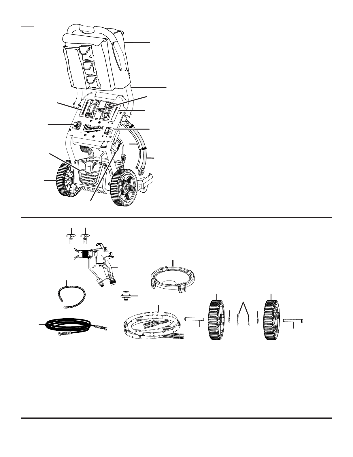
Fig. 1
A - Pump (pompe, bomba )
D
K
B
C
J
E
G
B - Prime/spray selector [sélecteur « prime/spray » (amorçage/
pulvérisation), selector de cebado/rociado]
C - Variable pressure control [Régulateur de pression « HIGH/LOW »
(élevée/faible), control de presión ALTA/BAJA]
D - Removable accessory storage bag (sac de rangement amovible pour
accessoires, bolsa de almacenamiento de accesorios desmontable)
E - HI/OFF/FINISH switch (Sélecteur «élevé/arrêt/finition », Interruptor
Alto/Apagado/Acabado)
I
F - Wheels (roues, ruedas)
G - Return tube (tube de retour, tubo de retorno)
H - Intake tube (tube d’admission, tubo de entrada)
I - Folding handle (poignée repliable, mango plegable)
J - Air connect outlet (raccord d’admission d’air, toma de corriente de la
conexión de aire)
K - Paint connect outlet (raccord d’admission de la peinture, toma de
corriente de la conexión de la pintura)
L - 2-stage turbine (turbine à deux phases, turbina de 2 etapas)
L
H
F
A
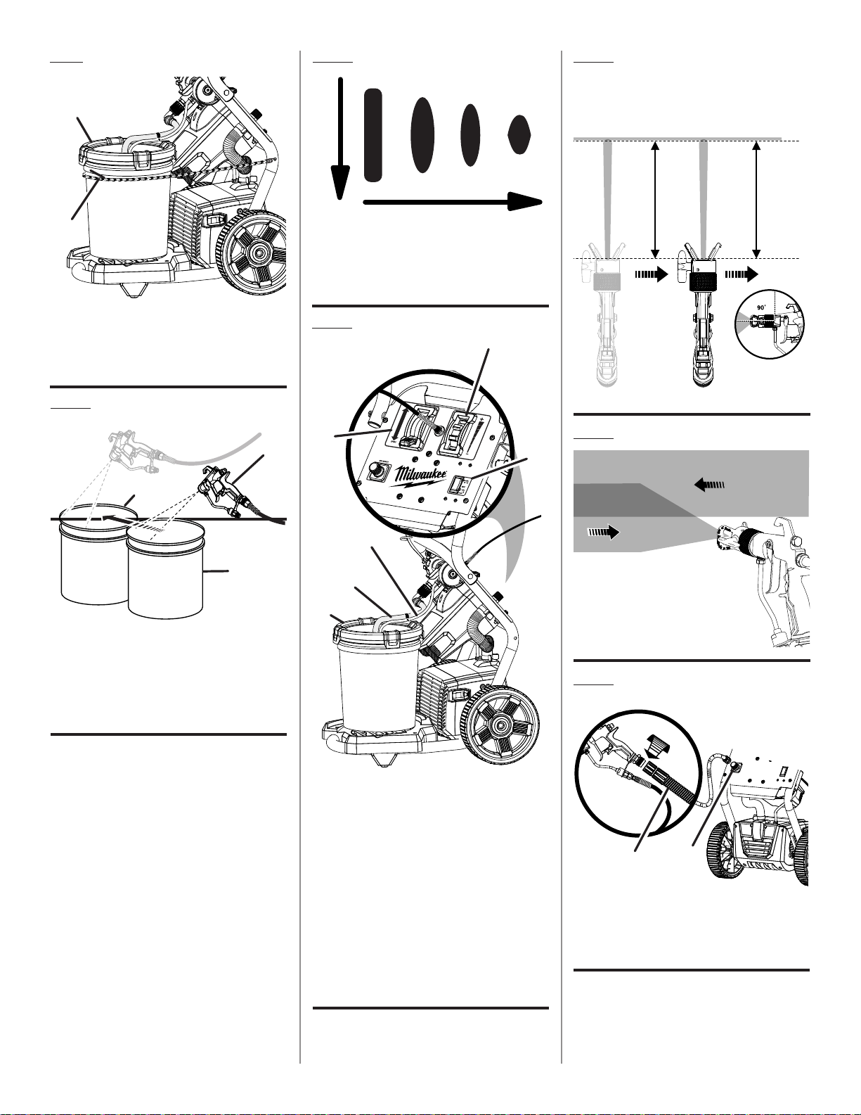
Fig. 2
B
A
C
E
H
G
F
A - 310 Reversible spray tip (embout de pulvérisation réversible 310, punta
de rociado invertible 310)
B - 619 Reversible spray tip (embout de pulvérisation réversible 619, punta
de rociado invertible 619 )
C - Pistol-grip sprayer with nozzle tip guard (pistolet de pulvérisation avec
protecteur d’embout, rociador con empuñadura de pistola con protección
para la punta de la boquilla)
D - 5 Gallon paint container lid [station de peinture avec réservoir de peinture
de 19 l (5 gal) et couvercle, estación de pintura con contenedor de 19 l
(5 gal.) y tapa]
E - Elastic strap (courroie élastique, correa elástica)
D
KK
L
J
I
F - 25 Ft. grounded type high pressure fluid hose [tuyau flexible haute
pression mis à la terre de 7,62 m (25 pi), manguera de alta presión con
conexión a tierra de 7,62 m (25 pi)]
G - 25 ft. air hose [tuyau flexible de la soufflante de 7,62 m (25 pi), tubos de
pintura de 7,62 m (25 pi)]
H - Garden hose attachment (accessoire du boyau d’arrosage, accesorio
para manguera de jardín)
I - Axle (essieu, eje)
J - Washer (rondelle, arandela)
K - Wheel (roue, rueda)
L - Hitch pin (goupille de sûreté, pasador del enganche)
J
I
ii

Fig. 3 Fig. 5 Fig. 7
A
B
A
C
D
A - Axle (essieu, eje)
B - Wheel (roue, rueda)
C - Washer (rondelle, arandela)
D - Hitch pin (goupille de sûreté, pasador del
enganche)
Fig. 4
B
D
C
A
A - Nozzle tip guard (protecteur d’embout,
protección para la punta de la boquilla)
B - Reversible spray tip (embout de pulvérisation
réversible, punta de rociado invertible)
C - Nozzle sleeve (manche de la buse, casquillo
de boquilla)
D - Saddle (selle de renforcement, carro
portaherramientas)
E - Rubber seal (rondelles de caoutchouc,
arandela de goma)
F - Lock-off lever (levier de blocage de la
gâchette, palanca de seguro de apagado)
B
C
E
D
F
A
B
B
A
A - Handle (poignée, mango)
B - Handle knob (bouton de poignée, perilla de la
barra del mango)
E
A - High pressure hose (tuyau flexible pression,
manguera de alta presión con conexión)
B - Paint connect outlet (raccord d’admission de
la peinture, toma de corriente de la conexión
de la pintura)
C - Pistol-grip sprayer (pistolet de pulvérisation,
rociador con empuñadura de pistola)
D - Adjustable wrench (clé à ouverture réglable,
llave ajustable)
E - Air hose (tuyau flexible de la soufflante,
tubos de pintura)
F - Air connect outlet (raccord d’admission d’air,
toma de corriente de la conexión de aire)
F
Fig. 6
A
B
A - Lock-off lever (levier de blocage de la
gâchette, palanca de seguro de apagado)
B - Trigger (gâchette, gatillo)
Fig. 8
A
D
E
B
C
A - Paint connect outlet (raccord d’admission de
la peinture, toma de corriente de la conexión
de la pintura)
B - Air connect outlet (raccord d’admission d’air,
toma de corriente de la conexión de aire)
C - HI/OFF/FINISH switch (sélecteur «élevé/arrêt/
finition », interruptor Alto/Apagado/Acabado)
D - Variable pressure control (régulateur de
pression , control de la presión variable)
E - PRIME/SPRAY lever (levier « PRIME/SPRAY »
(amorçage/pulvérisation), palanca de cebado/
rociado)
iii
WASTE
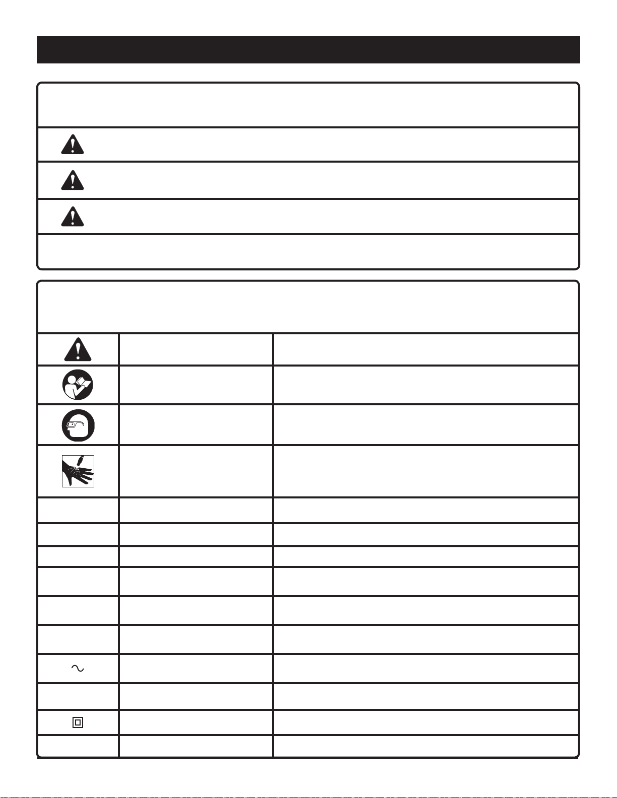
Fig. 9
Fig. 11
Fig. 13
A
B
A - 5 Gallon paint container lid [réservoir de
peinture de 13,25 l (3,5 gal), estación de
pintura con contenedor de 13,25 l (3,5 gal.)]
B - Elastic strap (courroie élastique, correa
elástica)
Fig. 10
C
EVEN STROKES
PASSES UNIFORMES
CORTES PAREJOS
10 - 12 in.
10 - 12 po
10 - 12 pulg.
B
A
A - Orifice size increases (la taille d’orifice
augmente, el tamaño del orificio aumenta)
B - Fan width decreases (la largeur de ventilateur
diminue anchura del ventilador disminuye)
Fig. 12
E
A
F
Fig. 14
D
B
A - Pistol-grip sprayer (pistolet de pulvérisation,
rociador con empuñadura de pistola)
B - Waste container (contenant à déchets,
contenedor de desechos)
C - Paint container (contenant de peinture,
contenedor de pintura)
B
A
C
A - Intake tube (tube d’admission, tubo de
entrada)
B - Return tube (tube de retour, tubo de retorno)
C - 5 Gallon paint container lid [station
de peinture avec réservoir de peinture
de 19 l (5 gal) et couvercle, estación
de pintura con contenedor de 19 l
(5 gal.) y tapa]
D - HI/OFF/FINISH switch (sélecteur «élevé/arrêt/
finition », interruptor Alto/Apagado/Acabado)
E - Variable pressure control (régulateur de
pression , control de la presión variable)
F - PRIME/SPRAY lever (levier « prime/spray »
(amorçage/pulvérisation) palanca de cebado/
rociado)
Fig. 15
B
A - Air connect outlet (raccord d’admission d’air,
toma de corriente de la conexión de aire)
B - Air hose (tuyau flexible de la soufflante),
tubos de pintura)
A
iv

WASTE
Fig. 16
Fig. 18
B
A
A
A
B
C
D
A - Intake tube (tube d’admission, tubo de entrada)
B - Filter (filtre, filtro)
Fig. 17
C
D
B
A
A - Trigger (gâchette, gatillo)
B - Lock-off lever (levier de blocage de la gâchette, palanca de seguro de
apagado)
C - Filter (filtre, filtro)
D - Nut (écrou, tuerca)
A - Waste container (contenant à déchets, contenedor de desechos)
B - Return tube (tube de retour, tubo de retorno)
C - Intake tube ((tube d’admission, tubo de entrada))
D - Garden hose (tuyau d’arrosage, manguera de jardín)
v

TABLE OF CONTENTS
Introduction ..................................................................................................................................................................... 2
Warranty .......................................................................................................................................................................... 2
Important Safety Instructions .......................................................................................................................................... 3
Specific Safety Rules ....................................................................................................................................................... 4
Symbols ........................................................................................................................................................................... 5
Electrical .......................................................................................................................................................................... 6
Features ........................................................................................................................................................................... 7
Assembly ......................................................................................................................................................................8-9
Operation .................................................................................................................................................................... 9-12
Maintenance .................................................................................................................................................................. 13
Troubleshooting ........................................................................................................................................................13-15
Parts Ordering / Service ...................................................................................................................................Back page
INTRODUCTION
This product has many features for making its use more pleasant and enjoyable. Safety, performance, and dependability
have been given top priority in the design of this product making it easy to maintain and operate.
WARRANTY
AIRLESS PAINT SPRAYER TWO YEAR LIMITED WARRANTY
Your MILWAUKEE airless paint sprayer is warranted to the original purchaser only to be free from defects in material and
workmanship. Subject to certain exceptions, MILWAUKEE will repair or replace any part on your MILWAUKEE airless paint
sprayer which is defective in material or workmanship for a period of two (2) years after the date of purchase. Return of the
product and a copy of proof of purchase to a service center authorized to service MILWAUKEE airless paint sprayers (a
“MILWAUKEE Authorized Airless Paint Sprayer Service Center”) freight prepaid and insured, are required for this warranty to
be effective. This warranty does not apply to damage from repairs made or attempted by anyone other than an Authorized
Airless Paint Sprayer Service Center, misuse, alterations, abuse, normal wear and tear, lack of maintenance, or accidents.
Warranty Registration is not necessary to obtain the applicable warranty on a MILWAUKEE airless paint sprayer. However,
proof of purchase in the form of a sales receipt or other information deemed sufficient by MILWAUKEE, is required. The
manufacturing date of the product will be used to determine the warranty period if no proof of purchase is provided at the
time warranty service is requested.
ACCEPTANCE OF THE EXCLUSIVE REPAIR AND REPLACEMENT REMEDIES DESCRIBED HEREIN IS A CONDITION OF THE
CONTRACT FOR THE PURCHASE OF EVERY MILWAUKEE PRODUCT. IF YOU DO NOT AGREE TO THIS CONDITION, YOU
SHOULD NOT PURCHASE THE PRODUCT. IN NO EVENT SHALL MILWAUKEE BE LIABLE FOR ANY INCIDENTAL, SPECIAL,
CONSEQUENTIAL OR PUNITIVE DAMAGES, OR FOR ANY COSTS, ATTORNEY FEES, EXPENSES, LOSSES OR DELAYS
ALLEGED TO BE AS A CONSEQUENCE OF ANY DAMAGE TO, FAILURE OF, OR DEFECT IN ANY PRODUCT INCLUDING, BUT
NOT LIMITED TO, ANY CLAIMS FOR LOSS OF PROFITS. SOME STATES DO NOT ALLOW THE EXCLUSION OR LIMITATION
OF INCIDENTAL OR CONSEQUENTIAL DAMAGES, SO THE ABOVE LIMITATION OR EXCLUSION MAY NOT APPLY TO
YOU. THIS WARRANTY IS EXCLUSIVE AND IN LIEU OF ALL OTHER EXPRESS WARRANTIES, WRITTEN OR ORAL. TO THE
EXTENT PERMITTED BY LAW, MILWAUKEE DISCLAIMS ANY IMPLIED WARRANTIES, INCLUDING WITHOUT LIMITATION
ANY IMPLIED WARRANTY OF MERCHANTABILITY OR FITNESS FOR A PARTICULAR USE OR PURPOSE; TO THE EXTENT
SUCH DISCLAIMER IS NOT PERMITTED BY LAW, SUCH IMPLIED WARRANTIES ARE LIMITED TO THE DURATION OF THE
APPLICABLE EXPRESS WARRANTY AS DESCRIBED ABOVE. SOME STATES DO NOT ALLOW LIMITATIONS ON HOW LONG
AN IMPLIED WARRANTY LASTS, SO THE ABOVE LIMITATION MAY NOT APPLY TO YOU. THIS WARRANTY GIVES YOU
SPECIFIC LEGAL RIGHTS, AND YOU MAY ALSO HAVE OTHER RIGHTS WHICH VARY FROM STATE TO STATE.
This warranty applies to product sold in the U.S.A., Canada and Mexico only.
TO GET SERVICE: Return your MILWAUKEE Airless Paint Sprayer, properly packaged and postage prepaid, to a MILWAUKEE
Authorized Airless Paint Sprayer Service Center for warranty or non-warranty service. To obtain the location of the nearest
MILWAUKEE Authorized Airless Paint Sprayer Service Center, call 1-877-203-0880 or consult the Airless Paint Sprayer category
of MILWAUKEE’s website at www.milwaukeetool.com.
2 — English

IMPORTANT SAFETY INSTRUCTIONS
WARNING:
SAVE THESE INSTRUCTIONS. To reduce the risks of
fire or explosion, electric shock, and the injury to persons, read and understand all instructions included in
this manual. Be familiar with the controls and the proper
usage of the equipment.
READ ALL INSTRUCTIONS
KNOW YOUR POWER TOOL. Read the operator’s
manual carefully. Learn the machine’s applications and
limitations as well as the specific potential hazards related
to this tool.
WARNING: To reduce the risk of fire or explosion:
Do not spray flammable or combustible materials near
an open flame or sources of ignition such as cigarettes,
motors, and electrical equipment.
For units intended for use with only water-based or
mineral spirit-type materials with a minimum flash point
of 140°F (60°C), do not spray or clean with liquids
having a flash point less than 140°F (60°C).
Paint or solvent flowing through the equipment is able
to result in static electricity. Static electricity creates
a risk of fire or explosion in the presence of paint or
solvent fumes. All parts of the spray system, including
the pump, hose assembly, pistol-grip sprayer, and
objects in and around the spray area shall be properly
grounded to protect against static discharge and
sparks.
Use only conductive or grounded high-pressure airless
paint sprayer hoses specified by the manufacturer.
Verify that all containers and collection systems are
grounded to prevent static discharge.
Connect to a grounded outlet and use grounded
extension cords. Do not use a 3 to 2 adapter.
Do not use a paint or a solvent containing halogenated
hydrocarbons.
Keep spray area well ventilated. Keep a good supply
of fresh air moving through the area. Keep pump
assembly in a well ventilated area.
Do not smoke in the spray area.
Do not operate light switches, engines, or similar spark
producing products in the spray area.
Keep area clean and free of paint or solvent containers,
rags, and other flammable materials.
Know the contents of the paints and solvents being
sprayed. Read all Material Safety Data Sheets (MSDS)
and container labels provided with the paints and
solvents. Follow the paint and solvent manufacturer’s
safety instructions.
Fire extinguisher equipment shall be present and
working.
WARNING: To reduce the risk of skin injection:
Do not aim the nozzle at, or spray any person or
animal.
Keep hands and other body parts away from the
discharge. For example, do not try to stop leaks with
any part of the body.
Always use the nozzle tip guard. Do not spray without
nozzle tip guard in place.
Only use a spray tip specified by the manufacturer.
Use caution when cleaning and changing spray tips.
In the case where the spray tip clogs while spraying,
follow the manufacturer’s instructions for turning off
the unit and relieving the pressure before removing
the spray tip to clean.
Do not leave the unit energized or under pressure while
unattended. When the unit is not in use, turn off the
unit and relieve the pressure in accordance with the
manufacturer’s instructions.
High pressure spray is able to inject toxins into
the body and cause serious bodily injury. In the
event that injection occurs, seek medical attention
immediately.
Check hoses and parts for signs of damage. Replace
any damaged hoses or parts.
This system is capable of producing 3000 psi. Only use
replacement parts or accessories that are specified by
the manufacturer and are rated a minimum of 3200 psi.
Always engage the trigger lock when not spraying.
Verify the trigger lock is functioning properly.
Verify that all connections are secure before operating
the unit.
Know how to stop the unit and bleed pressure quickly.
Be thoroughly familiar with the controls.
For household use only.
WARNING: To reduce the risk of injury:
Always wear appropriate gloves, eye protection
marked to comply with ANSI Z87.1, and a respirator
or mask when painting.
Do not operate or spray near children. Keep children
away from equipment at all times.
Do not overreach or stand on an unstable support.
Keep effective footing and balance at all times.
Stay alert and watch what you are doing.
Do not operate the unit when fatigued or under the
influence of drugs or alcohol.
Do not kink or overbend the hose.
Do not expose the hoses to temperatures or to
pressur es in ex ce ss of those specified by the
manufacturer.
Do not use the hose as a strength member to pull or
lift the equipment.
3 — English

SPECIFIC SAFETY RULES
Keep guards in place and in working order. Never
operate the tool with any guard or cover removed. Make
sure all guards are operating properly before each use.
To reduce the risk of injury, keep children and visitors
away. All visitors should wear safety glasses and be kept
a safe distance from work area.
Keep the area of operation clear of all persons,
particularly small children, and pets.
Use right tool. Don’t force tool or attachment to do a
job it was not designed for. Don’t use it for a purpose not
intended.
Do not operate the equipment while barefoot or when
wearing sandals or similar lightweight footwear. Wear
protective footwear that will protect your feet and improve
your footing on slippery surfaces.
Exercise caution to avoid slipping or falling.
Always wear eye protection with side shields marked
to comply with ANSI Z87.1. Failure to do so could result
in fluids entering your eyes resulting in possible serious
injury.
Use only recommended accessories. The use of im-
proper accessories may cause risk of injury.
Follow the maintenance instructions specified in this
manual.
Check damaged parts. Before further use of the
guard or other part that is damaged should be carefully
checked to determine that it will operate properly and
perform its intended function. Check for alignment of
moving parts, binding of moving parts, breakage of parts,
mounting, and any other conditions that may affect its
operation. A guard or other part that is damaged must
be properly repaired or replaced by an authorized service
center to avoid risk of personal injury.
Never leave tool running unattended. Turn power off.
Don’t leave tool until it comes to a complete stop.
Follow manufacturer’s recommendations for safe
loading, unloading, transport, and storage of
machine.
Be thoroughly familiar with controls. Know how to stop
the product and bleed pressure quickly.
Keep tool dry, clean, and free from oil and grease.
Always use a clean cloth when cleaning. Never use brake
fluids, gasoline, petroleum-based products, or any solvents to clean tool.
Do not use tool if switch does not turn it off. Have
defective switches replaced by an authorized service
center.
Before cleaning, repairing, or inspecting, shut off the
motor, release pressure, and make certain all moving
parts have stopped.
Avoid dangerous environment. Don’t use in damp or
wet locations or expose to rain. Keep work area well
lit.
tool, a
Never direct a paint stream toward people or pets,
or any electrical device.
Never start the machine if ice has formed in any part
of the equipment.
WARNING: High pressure spray can be dangerous
if subject to misuse. The spray must not be directed
at persons, animals, electrical devices, or the machine
itself.
Keep away from hot parts.
Check bolts and nuts for looseness before each use.
A loose bolt or nut may cause serious motor problems.
Before storing, allow the product to cool.
Store in a cool, well-ventilated area, safely away from
spark and/or flame-producing equipment.
When servicing use only identical replacement parts.
Use of any other parts may create a hazard or cause
product damage.
Never use the sprayer without a spray tip in-
stalled.
An injection injury can lead to possible amputation.
See a physician immediately.
Never put your hand in front of the spray tip when in
use. Gloves will not always provide protection against
an injection injury.
Wear protective clothing to keep paint off skin and
hair, along with a mask or respirator during use. Paints,
solvents, and other materials can be harmful if inhaled or
if they come into contact with the body.
Always unplug the paint sprayer, shut the unit off
and release pressure before servicing, cleaning
the tip or guard, changing the tip, or leaving unattended.
Plastic can cause sparks. Never hang plastic to
enclose a spray area. Do not use plastic drop cloths
when spraying flammable materials.
Do not spray outdoors on windy days.
Do not attempt to clean or unclog the spray tip with
your finger.
Make sure your extension cord is in good condition.
When using an extension cord, be sure to use one heavy
enough to carry the current your product will draw. A wire
gauge size (A.W.G.) of at least 12 is recommended for an
extension cord 50 feet or less in length. A cord exceeding
100 feet is not recommended. If in doubt, use the next
heavier gauge. The smaller the gauge number, the heavier
the cord. An undersized cord will cause a drop in line
voltage resulting in loss of power and overheating.
Save these instructions. Refer to them frequently and
use them to instruct other users. If you loan someone this
tool, loan them these instructions also.
4 — English
SYMBOLS
The following signal words and meanings are intended to explain the levels of risk associated with this product.
SYMBOL SIGNAL MEANING
DANGER:
WARNING:
CAUTION:
CAUTION:
Some of the following symbols may be used on this product. Please study them and learn their meaning. Proper
interpretation of these symbols will allow you to operate the product better and safer.
Indicates an imminently hazardous situation, which, if not avoided, will result
in death or serious injury.
Indicates a potentially hazardous situation, which, if not avoided, could result
in death or serious injury.
Indicates a potentially hazardous situation, which, if not avoided, may result in
minor or moderate injury.
(Without Safety Alert Symbol) Indicates a situation that may result in property
damage.
SYMBOL NAME DESIGNATION/EXPLANATION
Safety Alert Indicates a potential personal injury hazard.
Read The Operator’s Manual
Eye Protection
To reduce the risk of injury, user must read and understand
operator’s manual before using this product.
Always wear eye protection with side shields marked to comply
with ANSI Z87.1.
To reduce the risk of injection or injury, never direct a fluid stream
Risk of Injection
V Volts Voltage
PSI Pounds Per Square Inch Fluid Pressure
GPM Gallons Per Minute Amount fluid used per minute of continuous use.
A Amperes Current
Hz Hertz Frequency (cycles per second)
min Minutes Time
Alternating Current Type of current
n
o
No Load Speed Rotational speed, at no load
Class II Tool Double-insulated construction
towards people or pets or place any body part in the stream.
Leaking hoses and fittings are also capable of causing injection
injury. Do not hold hoses or fittings.
.../min Per Minute Revolutions, strokes, surface speed, orbits etc., per minute
5 — English

ELECTRICAL
EXTENSION CORDS
Use only 3-wire extension cords that have 3-prong grounding
plugs and 3-pole receptacles that accept the product’s plug.
When using a power tool at a considerable distance from
the power source, use an extension cord heavy enough to
carry the current that the product will draw. An undersized
extension cord will cause a drop in line voltage, resulting in
a loss of power and causing the motor to overheat. Use the
chart provided below to determine the minimum wire size
required in an extension cord. Only round jacketed cords
listed by Underwriter’s Laboratories (UL) should be used.
**Ampere rating (on product data plate)
0-2.0 2.1-3.4 3.5-5.0 5.1-7.0 7.1-12.0 12.1-16.0
Cord Length Wire Size (A.W.G.)
25' 16 16 16 16 14 14
50' 16 16 16 14 14 12
100' 16 16 14 12 10 —
**Used on 12 gauge - 20 amp circuit.
NOTE: AWG = American Wire Gauge
When working with the product outdoors, use an extension
cord that is designed for outside use. This is indicated by the
letters “W-A” or “W” on the cord’s jacket.
Before using an extension cord, inspect it for loose or
exposed wires and cut or worn insulation.
WARNING:
Keep the extension cord clear of the working area.
Position the cord so that it will not get caught on lumber,
tools, or other obstructions while you are working with a
power tool. Failure to do so can result in serious personal
injury.
GROUNDING INSTRUCTIONS
This product must be grounded. In the event of a malfunction
or breakdown, grounding provides a path of least resistance
for electric current to reduce the risk of electric shock.
This product is equipped with an electric cord having an
equipment-grounding conductor and a grounding plug. The
plug must be plugged into a matching outlet that is properly
installed and grounded in accordance with all local codes
and ordinances.
Do not modify the plug provided. If it will not fit the outlet,
have the proper outlet installed by a qualified electrician.
WARNING:
Improper connection of the grounding plug can result in a
risk of electric shock. When repair or replacement of the
cord is required, do not connect the grounding wire to
either flat blade terminal. The wire with insulation having
an outer surface that is green with or without yellow
stripes is the grounding wire.
Check with a qualified electrician or service personnel if
the grounding instructions are not completely understood,
or if in doubt as to whether the product is properly
grounded.
Repair or replace a damaged or worn cord immediately.
This product is for use on a nominal 120 V circuit and has
a grounding plug similar to the plug illustrated below. Only
connect the product to an outlet having the same configuration
as the plug. Do not use an adapter with this product.
WARNING:
Check extension cords before each use. If damaged
replace immediately. Never use the product with a
damaged cord since touching the damaged area could
cause electrical shock resulting in serious injury.
ELECTRICAL CONNECTION
This product is powered by a precision-built electric motor. It
should be connected to a power supply that is 120 V, AC only
(normal household current), 60 Hz. Do not operate this
product on direct current (DC). A substantial voltage drop
will cause a loss of power and the motor will overheat. If
the product does not operate when plugged into an outlet,
double check the power supply.
6 — English
GroundinG
Pin
GFCi reCePtaCle

FEATURES
PRODUCT SPECIFICATIONS
Flow Rate ............................................................0.31 GPM
Fluid Pressure...............................................800-3,000 PSI
Air Pressure ............................................................. 5-8 PSI
Input ................................. 120 V, AC only, 60 Hz, 15 Amps
Weight ...................................................................... 41 lbs.
KNOW YOUR AIRLESS PAINT SPRAYER
See Figure 1.
The safe use of this product requires an understanding of
the information on the product and in this operator’s manual
as well as a knowledge of the project you are attempting.
Before use of this product, familiarize yourself with all operating features and safety rules.
3000 PSI PISTON PUMP
Maintains pressure as needed for different applications.
25 FT. HIGH PRESSURE HOSE
The 25 ft. high pressure hose allows the user to spray a larger
area without moving the paint sprayer.
AIRLESS SPRAYING MODE
The pressurized fluid moving through the spray nozzle will
be atomized as it is sprayed.
BUCKET TRAY
Compatible with up to a 5-gallon container.
CONTROL PANEL
Single interface with all controls conveniently located.
DUAL-ACTION™ PISTOL-GRIP SPRAYER
The DUAL-ACTION™ pistol-grip sprayer easily switches
between airless and fine finish applications.
FINISH SPRAY TECHNOLOGY
The two-stage turbine delivers high volume, low pressure
(HVLP) spray for fine finish applications.
FOLDING HANDLE
The handle folds down for convenient storage.
INTAKE FILTER
The intake filter keeps debris from entering the paint
system.
ON-BOARD ACCESSORY STORAGE
The removable storage bag provides convenient storage
for the pistol-grip sprayer, spray tips, hose adaptor, high
pressure hose, and other accessories.
VARIABLE PRESSURE CONTROL
Lower pressure is for priming, cleaning, and for thinner
materials and finish spraying.
Higher pressure is ideal for latex and airless spraying
applications.
PRIME/SPRAY SELECTOR
Allows you to switch from PRIME mode to SPRAY mode.
REVERSIBLE SPRAY TIPS
The unit includes two reversible spray tips that clear paint
clogs quickly.
ELASTIC STRAP
Helps to secure the paint bucket to the body of the
sprayer.
7 — English
ASSEMBLY
UNPACKING
This product requires assembly.
Carefully lift the product from the carton and place on a
level work surface.
WARNING:
Do not use this product if any parts on the Loose Parts
List are already assembled to your product when you
unpack it. Parts on this list are not assembled to the
product by the manufacturer and require customer installation. Use of a product that may have been improperly
assembled could result in serious personal injury.
Inspect the tool carefully to make sure no breakage or
damage occurred during shipping.
Do not discard the packing material until you have care-
fully inspected and satisfactorily operated the tool.
If any parts are damaged or missing, please call
1-877-203-0880 for assistance.
LOOSE PARTS LIST
See Figure 2.
Description Qty.
5 Gallon container lid ......................................................1
DUAL-ACTION™ pistol-grip sprayer with
Nozzle tip guard ..............................................................1
Wheel .............................................................................2
Axle....... ...........................................................................2
Washer ............................................................................2
Hitch pin ..........................................................................2
25 Ft. air hose ..................................................................1
25 Ft. high pressure hose ................................................1
310 Reversible spray tip ..................................................1
619 Reversible spray tip ..................................................1
Garden hose attachment .................................................1
Elastic strap .....................................................................1
Operator’s manual (not shown) .......................................1
WARNING:
If any parts are damaged or missing do not operate this
tool until the parts are replaced. Use of this product
with damaged or missing parts could result in serious
personal injury.
WARNING:
Do not attempt to modify this tool or create accessories not recommended for use with this tool. Any such
alteration or modification is misuse and could result in a
hazardous condition leading to possible serious personal
injury.
WARNING:
Do not connect to power supply until assembly is
complete. Failure to comply could result in accidental
starting and possible serious personal injury.
TOOLS NEEDED
Adjustable wrench
INSTALLING THE WHEELS
See Figure 3.
To attach the wheels to the base:
Locate the axle.
Slip the axle through the wheel hole. Slide washer onto
axle.
Lifting the paint sprayer slightly, slide the axle, wheel,
and washer into the wheel mounting hole in the machine
base.
Push the hitch pin into the hole on the end of the axle to
secure assembly.
Repeat with the second wheel assembly.
FOLDING THE HANDLE
See Figure 4.
To raise the handle: pull the handle up until the handle
release knob snaps through the locking hole to secure
the handle in place.
To lower the handle (for storing): pull the handle release
knob on the right side of handle and lower.
WARNING:
Never use the handle to lift the paint sprayer. Failure
to heed this warning could result in serious personal
injury.
CONNECTING HIGH PRESSURE HOSE/
DUAL-ACTION™ PISTOL-GRIP SPRAYER
See Figure 5.
To connect the high pressure hose to the paint sprayer:
Screw the collar of the high pressure hose onto the paint
connect outlet located on the control panel.
Tighten securely with an adjustable wrench.
To connect the DUAL-ACTION™ pistol-grip sprayer to
the high pressure hose:
Screw the collar on the high pressure hose onto the
pistol-grip sprayer by turning the hose collar clockwise.
Use an adjustable wrench to turn and tighten the nut on
the hose end and tighten securely.
8 — English
ASSEMBLY
INSTALLING NOZZLE TIP GUARD ON
DUAL-ACTION™ PISTOL-GRIP SPRAYER
See Figures 6 - 7.
See operator’s instructions for flushing, priming, and cleaning
before installing a spray tip. Note all warnings regarding use
of DUAL-ACTION™ pistol-grip sprayer and the possibility
of injection.
Push the lock-off lever down to lock the sprayer trig-
ger.
Unscrew the nozzle tip guard.
NOTE: Small parts inside the tip guard can be easily
dropped and misplaced. Always remove the nozzle tip
guard carefully.
Insert tip sleeve into the nozzle tip guard while aligning
the holes.
OPERATION
WARNING:
Do not allow familiarity with this product to make you
careless. Remember that a careless fraction of a second is
sufficient to inflict serious injury.
Insert the desired reversible spray tip into the nozzle tip
guard, locking the sleeve into place.
Insert metal saddle into the nozzle tip guard. The metal
saddle should be securely seated on the reversible spray
tip.
Insert the rubber seal ridged side down onto the saddle
in the nozzle tip guard.
Thread nozzle tip guard assembly onto sprayer and tighten
securely.
Push spray tip securely into nozzle tip guard.
Keep the sprayer trigger locked when not in use.
APPLICATIONS
You may use this product for the purposes listed below:
Exterior painting and staining of decks, outdoor furniture,
fences, siding, and interior/exterior spray-painting of
walls, cabinets, and doors.
WARNING:
Always wear eye protection with side shields marked to
comply with ANSI Z87.1. Failure to do so could result
in fluids entering your eyes resulting in possible serious
injury.
WARNING:
Do not use any attachments or accessories not
recommended by the manufacturer of this product. The
use of attachments or accessories not recommended
can result in serious personal injury.
ACCESSORIES
All accessories used with this product must be rated greater
than 3200 psi. Ensure compatibility and fit before using any
accessory with this product.
WARNING:
Risk of fire or explosion - spray area must be well
ventilated and away from spark of flames. Failure to heed
this warning could result in serious personal injury.
9 — English
WARNING:
To reduce the risk of injection NEVER change spray tip
without setting the lock-off on the pistol-grip sprayer and
NEVER point sprayer at any part of the body, persons, or
unit itself. In case of skin injection, seek medical attention
immediately. Failure to heed this warning may cause
serious personal injury.
LOCKING THE DUAL-ACTION™ PISTOL-GRIP
SPRAYER
See Figure 6.
Always lock the sprayer trigger when you have stopped
spraying to prevent the sprayer from being bumped or
triggered accidentally and causing injection.
Push the lock-off lever down to lock the sprayer trig-
ger.
Push the lock-off lever toward the handle to unlock the
trigger.
RELEASE PRESSURE PROCEDURE
See Figure 8.
Always follow this procedure when shutting the airless/finish
paint sprayer OFF for any reason. This procedure releases
pressure in the high pressure hose.
Push the lock-off lever down to lock the sprayer trigger.
Turn HI/OFF/FINISH switch OFF.

OPERATION
Turn PRIME/SPRAY lever to PRIME. This releases pump
pressure.
Push the lock-off lever up to unlock the sprayer trig-
ger and point to inside wall of paint container releasing
unused paint or stain back into container. This releases
pressure in the hose and pistol-grip sprayer.
Push the lock-off lever down to lock the sprayer trigger.
Leave PRIME/SPRAY lever in the PRIME position until
ready to spray again.
FLUSHING THE AIRLESS PAINT SPRAYER
Before using the paint sprayer for the first time or before
beginning a new project or changing colors, it is important
to thoroughly flush the paint sprayer of any storage fluid,
previous cleaning fluid, or material left in the system. Follow
instructions for Cleaning the Airless Paint Sprayer before
beginning any project.
SET UP AND PRIMING
See Figures 8 - 10.
User must prime the unit before operating the sprayer. The
high pressure fluid hose should already be attached as
described in the Assembly section of this manual.
Place desired paint container onto the paint tray.
Secure container with elastic strap. Place 5 gallon
container lid on container.
NOTE: This unit will hold a 5 gallon or 1 gallon paint
container.
Lock the sprayer trigger.
Remove nozzle tip guard and spray tip from pistol-grip
sprayer.
Place intake tube in paint container.
Set return tube into a waste container.
Turn PRIME/SPRAY lever to PRIME.
Turn variable pressure control to PRIME.
Plug in the paint sprayer.
Turn HI/OFF/FINISH switch to HI.
When clean paint or stain begins to flow through return
tube, turn HI/OFF/FINISH switch OFF. set return tube
into paint container and clip to intake tube; Turn HI/OFF/
FINISH switch to HI.
Point DUAL-ACTION™ pistol-grip sprayer (without guard
and spray tip in place) into waste container.
Turn PRIME/SPRAY lever to SPRAY.
Unlock sprayer trigger.
Spray into waste container until all air, water, and cleaning
fluid is expelled and only paint or stain comes out.
NOTE: When the motor stops, this indicates that the
pump and hoses are under pressure. If the motor continues to run, re-prime by turning the prime/spray lever
to PRIME.
Lock the sprayer trigger.
Turn HI/OFF/FINISH switch OFF.
10 — English
Replace nozzle tip guard and reversible spray tip onto
pistol-grip sprayer.
Unit is ready to spray.
SELECTING A SPRAY TIP
See Figure 11.
Spray tips come in a variety of hole sizes and fan widths.
Your unit includes two reversible spray tips with a hole size
of .010 in. and .019 in. that will work for a wide variety of
applications. The 310 spray tip has a fan width of 6-8 in. and
is best for fine finish applications. The 619 spray tip has a fan
width of 12-14 in. and is best for airless applications.
HOLE SIZE: Spray tip hole size determines the flow rate,
which is the amount of paint that is discharged from
sprayer.
A larger hole size is best for thicker materials. A smaller hole
size is best for thinner materials.
FAN SIZE: Fan width determines the size of the spray pattern
when sprayer is held approximately 12 in. from surface to
be painted.
A narrow fan width will provide thicker coverage of material
and is better suited for small, tight areas. A wide fan width
will give thinner coverage of material and provide better
coverage on large, broad areas.
SPRAY TIP NUMBERS: When selecting a spray tip, the last
three numbers of the spray tip number contain information
on hole size and fan width.
For example, if the spray tip number is 1415, the 4, when
doubled is the approximate fan width of paint when applied
12 inches from surface. The last two numbers, 15, refer to
the hole size in inches. In this case .015 in.
Tip
hole
size
0.011
0.013
0.015
0.017
0.019
0.021
Light Medium Heavy
Stains Enamels Primers
•
• •
SPRAY TIP WEAR: It is important to replace spray tips
when they become worn. A worn spray tip will cause uneven
application and finish of material. Over time the spray tip hole
size increases and the width of the fan spray decreases.
When using latex paint, spray tips need to be replaced
between 15 and 40 gallons of use. For oil based materials,
replace spray tips after 35 to 60 gallons of use.
To increase the life of your spray tips, use the lowest pressure
setting needed to apply an even coating of material.
Coatings
Interior
Paints
• • •
• • •
• • •
Exterior
Paints
•
 Loading...