

Milwaukee M18 FORCE LOGIC 2879-20 Operator's Manual
OPERATOR'S MANUAL
MANUEL de L'UTILISATEUR
MANUAL del OPERADOR
Cat. No. / No de cat.
2879-20
M18™ FORCE LOGIC™ 15T CRIMPER
SERTISSEUR UTILITAIRE 15T M18™ FORCE LOGIC™
CRIMPADORA 15T UTILITARIA M18™ FORCE LOGIC™
WARNING To reduce the risk of injury, user must read and understand operator's manual.
AVERTISSEMENT An de réduire le risque de blessures, l'utilisateur doit lire et bien
comprendre le manuel.
ADVERTENCIA Para reducir el riesgo de lesiones, el usuario debe leer y entender el manual.

GENERAL POWER TOOL
WARNING
SAFETY WARNINGS
Read all safety warnings, instruc-
tions provided with this power tool. Failure to
follow all instructions listed below may result in
electric shock, re and/or serious injury. Save all
warnings and instructions for future reference.
The term "power tool" in the warnings refers to your
mains-operated (corded) power tool or battery-oper-
ated (cordless) power tool.
tions, illustrations and specica-
WORK AREA SAFETY
• Keep work area clean and well lit. Cluttered or
dark areas invite accidents.
• Do not operate power tools in explosive atmo-
spheres, such as in the presence of ammable
liquids, gases or dust. Power tools create sparks
which may ignite the dust or fumes.
• Keep children and bystanders away while operating a power tool. Distractions can cause you to
lose control.
ELECTRICAL SAFETY
•
Power tool plugs must match the outlet. Never
modify the plug in any way. Do not use any
adapter plugs with earthed (grounded) power
tools. Unmodied plugs and matching outlets will
reduce risk of electric shock.
• Avoid body contact with earthed or grounded
surfaces, such as pipes, radiators, ranges and
refrigerators. There is an increased risk of electric
shock if your body is earthed or grounded.
• Do not expose power tools to rain or wet conditions. Water entering a power tool will increase the
risk of electric shock.
• Do not abuse the cord. Never use the cord for
carrying, pulling or unplugging the power tool.
Keep cord away from heat, oil, sharp edges
or moving parts. Damaged or entangled cords
increase the risk of electric shock.
• When operating a power tool outdoors, use an
extension cord suitable for outdoor use. Use of
a cord suitable for outdoor use reduces the risk of
electric shock.
• If operating a power tool in a damp location is
unavoidable, use a ground fault circuit interrupter (GFCI) protected supply. Use of an GFCI
reduces the risk of electric shock.
PERSONAL SAFETY
• Stay alert, watch what you are doing and use
common sense when operating a power tool. Do
not use a power tool while you are tired or under
the inuence of drugs, alcohol or medication. A
moment of inattention while operating power tools
may result in serious personal injury.
• Use personal protective equipment. Always
wear eye protection. Protective equipment such
as a dust mask, non-skid safety shoes, hard hat or
hearing protection used for appropriate conditions
will reduce personal injuries.
• Prevent unintentional starting. Ensure the switch
is in the off-position before connecting to power
source and/or battery pack, picking up or carry-
ing the tool. Carrying power tools with your nger
on the switch or energizing power tools that have
the switch on invites accidents.
• Remove any adjusting key or wrench before
turning the power tool on. A wrench or a key left
attached to a rotating part of the power tool may
result in personal injury.
• Do not overreach. Keep proper footing and balance at all times. This enables better control of the
power tool in unexpected situations.
• Dress properly. Do not wear loose clothing or
jewelry. Keep your hair and clothing away from
moving parts. Loose clothes, jewelry or long hair
can be caught in moving parts.
• If devices are provided for the connection of
dust extraction and collection facilities, ensure
these are connected and properly used. Use of
dust collection can reduce dust-related hazards.
• Do not let familiarity gained from frequent use
of tools allow you to become complacent and
ignore tool safety principles. A careless action can
cause severe injury within a fraction of a second.
POWER TOOL USE AND CARE
• Do not force the power tool. Use the correct
power tool for your application. The correct power
tool will do the job better and safer at the rate for
which it was designed.
• Do not use the power tool if the switch does not turn
it on and off. Any power tool that cannot be controlled
with the switch is dangerous and must be repaired.
• Disconnect the plug from the power source and/
or remove the battery pack, if detachable, from
the power tool before making any adjustments,
changing accessories, or storing power tools.
Such preventive safety measures reduce the risk of
starting the power tool accidentally.
• Store idle power tools out of the reach of children and do not allow persons unfamiliar with
the power tool or these instructions to operate
the power tool. Power tools are dangerous in the
hands of untrained users.
• Maintain power tools and accessories. Check for
misalignment or binding of moving parts, breakage of parts and any other condition that may
affect the power tool’s operation. If damaged,
have the power tool repaired before use. Many
accidents are caused by poorly maintained power
tools.
• Keep cutting tools sharp and clean. Properly
maintained cutting tools with sharp cutting edges
are less likely to bind and are easier to control.
• Use the power tool, accessories and tool bits
etc. in accordance with these instructions, taking into account the working conditions and the
work to be performed. Use of the power tool for
operations different from those intended could result
in a hazardous situation.
• Keep handles and grasping surfaces dry, clean
and free from oil and grease. Slippery handles
and grasping surfaces do not allow for safe handling
and control of the tool in unexpected situations.
BATTERY TOOL USE AND CARE
• Recharge only with the charger specied by the
manufacturer. A charger that is suitable for one
type of battery pack may create a risk of re when
used with another battery pack.
• Use power tools only with specically designated battery packs. Use of any other battery
packs may create a risk of injury and re.
2
• When battery pack is not in use, keep it away
WARNING
WARNING
WARNING
WARNING
WARNING
from other metal objects, like paper clips, coins,
keys, nails, screws or other small metal objects,
that can make a connection from one terminal
to another. Shorting the battery terminals together
may cause burns or a re.
• Under abusive conditions, liquid may be ejected
from the battery; avoid contact. If contact accidentally occurs, ush with water. If liquid con-
tacts eyes, additionally seek medical help. Liquid
ejected from the battery may cause irritation or burns.
• Do not use a battery pack or tool that is damaged or modied. Damaged or modied batteries
may exhibit unpredictable behavior resulting in re,
explosion or risk of injury.
• Do not expose a battery pack or tool to re or
excessive temperature. Exposure to re or temperature above 265°F (130°C) may cause explosion.
• Follow all charging instructions and do not
charge the battery pack or tool outside the
temperature range specied in the instructions.
Charging improperly or at temperatures outside
the specied range may damage the battery and
increase the risk of re.
SERVICE
• Have your power tool serviced by a qualied
repair person using only identical replacement
parts. This will ensure that the safety of the power
tool is maintained.
• Never service damaged battery packs. Service
of battery packs should only be performed by the
manufacturer or authorized service providers.
SPECIFIC SAFETY RULES FOR
CRIMPER
•
damage, work on deenergized lines when
possible. Tool is not insulated. Should
work on energized lines be required, ensure all
proper precautions, including those contained
in NFPA 70E, have been taken rst.
•Use tool only with compatible dies and connec-
tors for which they are rated. Jaws, dies, and
connectors must be used in an APPROVED
COMBINATION to achieve a successful op-
eration. Improper combinations can result in a
faulty crimp. Electric shock, re, explosion, and
property damage could occur.
•Keep hands away from crimping jaws while tool
is in use. Fingers could be crushed.
•To reduce the risk of injury, wear safety goggles
or glasses with side shields when operating or
servicing the tool.
•Inspect and discard workpieces with cracks or
wear before use. Materials may crack or shatter.
•Follow connector manufacturers' installation
instructions. Other uses may cause damage to
the tool, accessories, and workpiece.
•
erable amount of dust, use an OSHA compliant
dust extraction solution in accordance with the
solution’s operating instructions.
• Always use common sense and be cautious when
using tools. It is not possible to anticipate every
situation that could result in a dangerous outcome.
To reduce the risk of arc ash,
electric shock and property
To reduce the risk of injury in applications that produce a consid-
Do not use this tool if you do not understand these
operating instructions or you feel the work is beyond
your capability; contact Milwaukee Tool or a trained
professional for additional information or training.
•
Maintain labels and nameplates. These carry im-
portant information. If unreadable or missing, contact
a MILWAUKEE service facility for a free replacement.
•
construction activities contains chemicals known to
cause cancer, birth defects or other reproductive
harm. Some examples of these chemicals are:
• lead from lead-based paint
• crystalline silica from bricks and cement and other
masonry products, and
•
arsenic and chromium from chemically-treated lumber.
Your risk from these exposures varies, depending
on how often you do this type of work. To reduce
your exposure to these chemicals: work in a well
ventilated area, and work with approved safety
equipment, such as those dust masks that are spe-
cially designed to lter out microscopic particles.
Some dust created by power sanding,
sawing, grinding, drilling, and other
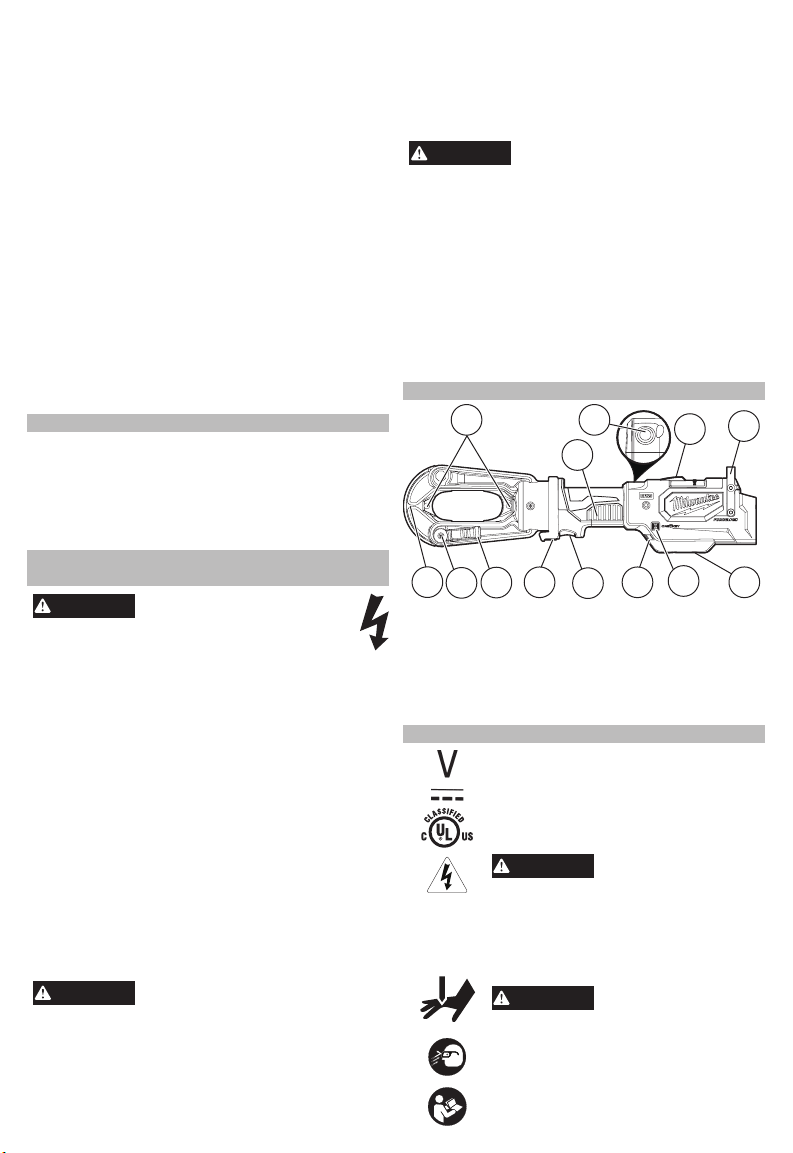
FUNCTIONAL DESCRIPTION
1
13
1. Die Release pins
2. Handle
3. Manual release button
4. LED Crimp indicator
5. Hanger
6. ONE-KEY™ coin
battery door
12
11
10
3
4
2
7
8
9
7. ONE-KEY™ indicator
8. Worklight LEDs
9. Trigger
10. Reverse button
11. Jaw release lever
12. Jaw lock pin
13. Swinging jaw
SYMBOLOGY
Volts
Direct Current
United States and Canada
To reduce the risk of injury, wear safety
Read operator's manual.
3
Underwriters Laboratories, Inc.
To reduce the risk of arc
property damage, work on deenergized
lines when possible. Tool is not
insulated. Should work on energized
lines be required, ensure all proper
precautions, including those contained
in NFPA 70E, have been taken rst.
is in use. Fingers could be crushed.
goggles or glasses with side shields
when operating or servicing the tool.
ash, electric shock and
Keep hands away from
crimping jaws while tool
5
6
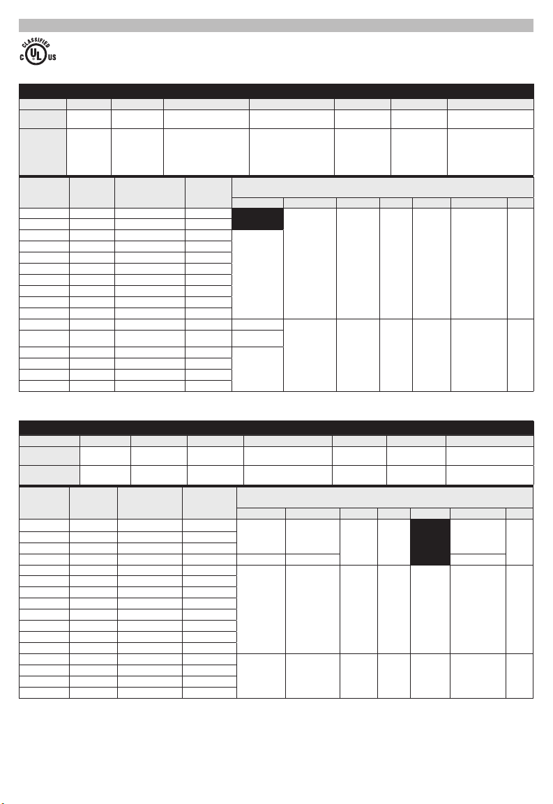
TABLE A
Connections made with this tool (2879-20), Adapter (49-15-PUAD) and combination of die
and connector part numbers in the charts below produce cULus Classied crimps according to the UL 486A-B classication standards.
Anderson Blackburn® Burndy ILSCO Panduit Penn-Union T&B
Splice
Model #'s
Lug
Model #'s
Wire
Size
#8 AWG RED 49-12-U008C 8
#6 AWG BLUE 49-12-U006C 6
#4 AWG GRAY 49-12-U004C 4
#2 AWG BROWN 49-12-U002C 2
#1 AWG GREEN 49-12-U001C 1
1/0 AWG PINK 49-12-U01AC 1/0
2/0 AWG BLACK 49-12-U02AC 2/0
3/0 AWG ORANGE 49-12-U03AC 3/0
4/0 AWG PURPLE 49-12-U04AC 4/0
250 MCM YELLOW 49-12-U250C 250
300 MCM WHITE 49-12-U300C 300 2
350 MCM RED 49-12-U350C 350
400 MCM BLUE 49-12-U400C 400
500 MCM BROWN 49-12-U500C 500
600 MCM GREEN 49-12-U600C 600
750 MCM BLACK 49-12-U750C 750
Model #'s
Model #'s
Wire
Size
#8 AWG BLUE 49-12-U008 8
#6 AWG GRAY 49-12-U006 6
#4 AWG GREEN 49-12-U004 4
#2 AWG PINK 49-12-U002 2 1 1 1
#1 AWG GOLD 49-12-U001 1
1/0 AWG TAN 49-12-U01A 1/0
2/0 AWG OLIVE 49-12-U02A 2/0
3/0 AWG RUBY 49-12-U03A 3/0
4/0 AWG WHITE 49-12-U04A 4/0
250 MCM RED 49-12-U250 250
300 MCM BLUE 49-12-U300 300
350 MCM BROWN 49-12-U350 350
400 MCM GREEN 49-12-U400 400
500 MCM PINK 49-12-U500 500
600 MCM BLACK 49-12-U600 600
750 MCM YELLOW 49-12-U750 750
Splice
Lug
VHS,
VHSS
VHCL,
VHCS
Die
Color Cat. No.
Anderson Blackburn® Burndy ILSCO Panduit Penn-Union T&B
Die
Color Cat. No.
CSP,
CU
CTL,
CTL-2,
CTL-L,
LCN
YS, YS-L,
YS-T
YA, YAZ, YA-L, YA-2L,
YA-2LN, YA-L-NT,
YA-L-2NT, YA-L-TC,
YA-L-2TC, YA-2N,
YA-TC, YA-2TC
Die
Indentation
Mark
Splices:
CT, CTL SCH, SCL,
CLN, CLND, CLNS,
CLW, CLWD, CRA,
CRB, CRA-L, CRB-L,
CRA-2L, CRB-2L,
CSW, CSWS
Anderson Blackburn
1
Lugs: 2
N/A
2
Dual Rated Lugs & Splices
VACS ASP YS-A AS,
VACL ATL YA-A,
YA-ATN
Die
Indentation
Mark
ASN
ACL, ACN, ALND,
ALNS, 2ACL, 2ACN
Anderson Blackburn
Lugs: N/A
Splices:
1
2 2 2 2 2 2 2
3 3 3 3 3 3 3
SCS, SCSS
LCA, LCAS,
LCB, LCC,
LCD
Lugs: Total # of Crimps
Splices: # of Crimps per Side
®
Burndy ILSCO Panduit Penn-Union T&B
1 1 1 1 1 1
2 2 2 2 2 2
SA BCUA 60501-60578
LAA,
LAB
Lugs: Total # of Crimps
Splices: # of Crimps per Side
®
Burndy ILSCO Panduit Penn-Union T&B
Lugs: 1
Splices:
N/A
1 1
BBCU,
BCU
BBLU,
BLU
BLUA 60101-60178,
54504-54523-TB,
54804-54823
54104-54123-TB,
54204-54223,
54850BE-54880BE,
54930BE-54923BE
60230-60278
Lugs: 1
Splices: N/A
1
Additional crimps would not negatively affect the integrity of the connection so long as they
are uniformly placed between the intended crimp area of the connector, typically outlined
with color bands or knurls. For the latest listing of approvals, visit milwaukeetool.com.
For technical or service assistance, contact Corporate After Sales Service Technical Sup-
port with technical, service/repair, or warranty questions. 1-800-SAWDUST (1.800.729.3878).
Copper Short & Long Barrel Lugs & Splices
4
Cat. No. ..................................................... 2879-20
WARNING
WARNING
WARNING
WARNING
WARNING
WARNING
Volts .............................................................. 18 DC
Battery Type .................................................M18™
Charger Type ................................................M18™
Recommended Ambient
Operating Temperature ......................0°F to 122°F
Force ..........................................................15 Tons
Capacity............................#8AWG - 1500 MCM Cu
#8AWG - 1250 MCM AI
Adapter Cat. No. ...............................49-15-PUAD
ASSEMBLY
Recharge only with the charger
SPECIFICATIONS
cic charging instructions, read the operator’s
manual supplied with your charger and battery.
To remove the battery, push in the release buttons
and pull the battery pack away from the tool.
To insert the battery, slide the pack into the body
of the tool. Make sure it latches securely into place.
may be hazardous.
compatible dies and connectors for which they
are rated. Jaws, dies, and connectors must be
used in an approved combination to achieve a
successful operation. Improper combinations
can result in a faulty crimp. Electric shock, re,
explosion, and property damage could occur.
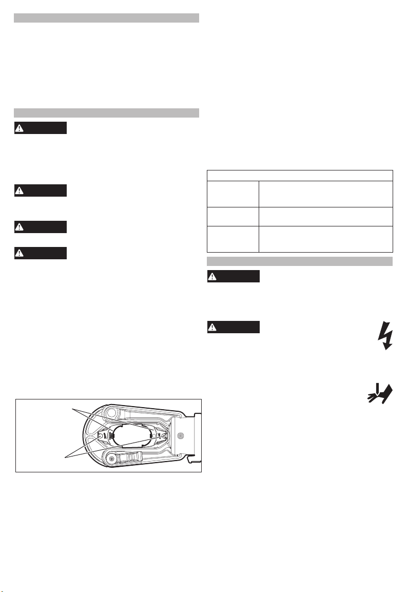
Inspect adapter before use. Only use an adapter
with "U" dies. Remove adapter when using "P" dies.
1. Remove the battery pack.
2. To install, pull out the release pins and slide the
adapter pieces in each side of the jaws. Adapter
pieces will snap into place after pins are released.
Tug on adapter pieces to ensure they are secure.
3. To remove, pull out the release pins and slide
adapter pieces out from each side of the jaws.
U-Die Adapter
(49-15-PUAD)
Release pins
Inspect dies and connectors before use. Only use
properly matched dies and connectors for the crimp-
ing jaws. Refer to Specications and Table A for die/
connector compatibility.
Only use "P" dies without the adapter, or "U" dies
with the adapter.
NOTE: Install the smaller die piece into the swinging
jaw to ensure the jaws will open fully.
1. Remove the battery pack.
2. Slide the appropriate dies into each side of the
crimping jaws.
specied for the battery. For spe-
Removing/Inserting the Battery
Always remove battery pack before
changing or removing accessories.
Only use accessories specically
recommended for this tool. Others
An incomplete or faulty crimp could
cause a re. Use tool only with
Inserting/Removing Adapter
Changing the Dies
3. When using "P" dies, pull out the release pins and
slide the dies into each side of the jaws. Dies will
snap into place after pins are released. Tug on
dies to ensure they are secure.
4. When using "U" dies, rst install the adapter, then
snap the "U" dies into each side of the jaws. Tug
on dies to ensure they are secure.
5. To remove "P" dies, pull out the release pin for
each side of the crimping jaws. Pull out dies.
6. To remove "U" dies, used with the adapter, press
the die release buttons on the adapter pieces and
slide out dies.
To learn more about the ONE-KEY™ function-
ality for this tool, please reference the Quick
Start guide included with this product or go to
milwaukeetool.com/One-Key. To download the
ONE-KEY™ app, visit the App Store or Google Play
from your smart device.
Solid Blue Wireless mode is active and ready
Blinking Blue Tool is actively communicating with
Blinking Red Tool is in security lockout and can
ONE-KEY™
ONE-KEY™ Indicator
to be congured via the ONE-KEY™
app.
the ONE-KEY™ app.
be unlocked by the owner via the
ONE-KEY™ app.
OPERATION
To reduce the risk of injury, always
to comply with ANSI Z87.1.
When working in dusty situations, wear appro-
priate respiratory protection or use an OSHA
compliant dust extraction solution.
damage, work on deenergized lines when
possible. Tool is not insulated. Should work
on energized lines be required, ensure all proper
precautions, including those contained in NFPA
70E, have been taken rst.
Keep hands away from crimping jaws
while tool is in use. Fingers could be
crushed.
Before crimping:
• Inspect the jaws and dies for cracks or other dam-
age. Do not use damaged jaws or dies. Contact a
MILWAUKEE service facility.
• Ensure dies are properly installed.
• Use the 49-15-PUAD adapter with "U" dies.
• Jaws, dies, connectors, and cables must be used
in an APPROVED COMBINATION. Improper
combinations can result in a faulty crimp.
• Inspect and discard workpieces with cracks or wear
before use. Materials may crack or shatter.
• Follow installation specications as specied in
Table A using an approved combination of jaws,
dies, connectors and cables as indicated. Other
uses may cause damage to the tool, accessories,
and workpiece.
1. Install the dies.Use adapter with "U" dies.
2. Insert battery pack.
5
wear proper eye protection marked
To reduce the risk of arc ash,
electric shock and property
Crimping
WARNING
WARNING
WARNING
3. Rotate the jaws to the desired angle.
WARNING
4. Open the jaws by sliding the jaw release lever.
5. Place jaws around workpiece and close the swinging jaw. Press in the locking pin.
6.
Crimps should be uniformly placed on the barrel
of the connector.
7.
Crimps should be reasonably placed within the
color bands or knurled area of the connector.
-For splices, begin crimping in the center,
working
-
towards the barrel.
8. Hold tool securely.
9. Press and hold the trigger. When the cycle is
complete the tool will automatically return to its
starting position. An LED will light the workpiece
when the trigger is pulled.
10. Release the trigger.
11.
The die identier is stamped into the connector
during the crimp.
12. Continue crimping according to the instructions
in Table A.
NOTE: After the cycle reaches a certain point, the
crimp may automatically nish, even if the trigger
is released.
Indicator Denition
Solid Green Tool completed the operation and
Solid Red Tool completed the operation but did NOT
Flashing Red Tool did NOT complete the operation.
Flashing
Red/Green
(after Solid
Green or
Solid Red)
outward while alternating sides.
For lugs, begin crimping near the pad, working
LED
reached full crimping pressure.
reach full crimping pressure.
Tool has reached its service interval
(20,000 crimps). Red/Green flashing
will begin after the solid Red or Green
indicator for the operation is displayed.
Tool will stop operating after 25,000
cycles. Return tool to a MILWAUKEE
service facility for inspection and
preventative maintenance.
Reverse Button/Manual Release Button
If the jaws need to be opened without completing the
cycle, press the reverse button. Hold tool securely
until the ram retracts fully.
If the jaws must be opened without the battery pack
installed, press and hold the Manual Release Button
until the ram retracts fully.
MAINTENANCE
To reduce the risk of injury, always
battery pack from the charger or tool before
performing any maintenance. Never disassemble
the tool, battery pack or charger. Contact a
MILWAUKEE service facility for ALL repairs.
Keep your tool, battery pack and charger in good
repair by adopting a regular maintenance program.
Inspect your tool for issues such as undue noise,
misalignment or binding of moving parts, breakage of
parts, or any other condition that may affect the tool
operation. Return the tool, battery pack, and charger
to a MILWAUKEE service facility for repair. After six
months to one year, depending on use, return the
tool, battery pack and charger to a MILWAUKEE
service facility for inspection.
unplug the charger and remove the
Maintaining Tool
If the tool does not start or operate at full power with
a fully charged battery pack, clean the contacts on
the battery pack. If the tool still does not work properly, return the tool, charger and battery pack, to a
MILWAUKEE service facility for repairs.
ONE-KEY™
Chemical Burn Hazard.
lithium button/coin cell battery. A new
or used battery can cause severe in
ternal burns and lead to death in as
little as 2 hours if swallowed or enters the body.
Always secure the battery cover. If it does not
close securely, stop using the device, remove the
batteries, and keep it away from children. If you
think batteries may have been swallowed or en
tered the body, seek immediate medical attention.
An internal battery is used to facilitate full ONE-KEY™
functionality.
To replace the battery:
1. Remove the battery pack.
2. Remove the screw(s) and open the battery door.
3. Remove the old battery, keep it away from children,
and dispose of it properly.
4. Insert the new battery (3V CR2032), with the positive side facing up.
5. Close the battery door and tighten the screw
securely.
your tool, battery pack or charger in liquid or
allow a liquid to ow inside them.
Clean dust and debris from vents. Keep handles
clean, dry and free of oil or grease. Use only mild
soap and a damp cloth to clean, since certain cleaning agents and solvents are harmful to plastics and
other insulated parts. Some of these include gasoline,
turpentine, lacquer thinner, paint thinner, chlorinated
cleaning solvents, ammonia and household deter-
gents containing ammonia. Never use ammable or
combustible solvents around tools.
For repairs, return the tool, battery pack and charger
to the nearest service center.
This device contains a
-
Internal Battery
To reduce the risk of personal injury and damage, never immerse
Cleaning
Repairs
ACCESSORIES
Use only recommended accesso-
For a complete listing of accessories, go online to
www.milwaukeetool.com or contact a distributor.
ries. Others may be hazardous.
SERVICE - UNITED STATES
1-800-SAWDUST (1.800.729.3878)
Monday-Friday, 7:00 AM - 6:30 PM CST
or visit www.milwaukeetool.com
Contact Corporate After Sales Service Technical
Support with technical, service/repair, or warranty
questions.
Email: metproductsupport@milwaukeetool.com
Become a Heavy Duty Club Member at
www.milwaukeetool.com to receive important
notications regarding your tool purchases.
6
-
 Loading...