

Milwaukee M18 FBJS, M18 FJS, M18 FUEL, M18 FUEL 2737-20, M18 FUEL 2737B-20 Operator's Manual
Page 1
Cat. No.
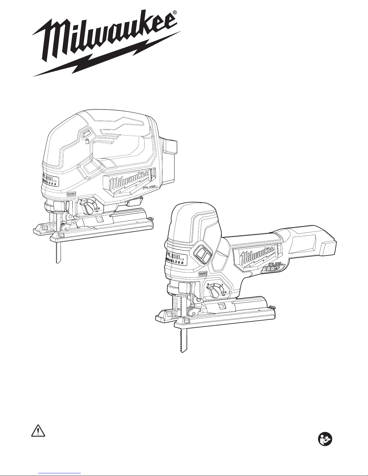
M18 FJS, M18 FBJS
M18™ FUEL™ JIGSAWS
OPERATOR'S MANUAL
To reduce the risk of injury, user must read and understand operator's manual.
WARNING
Page 2

2
GENERAL POWER TOOL
SAFETY WARNINGS
WARNING
Read all safety warnings, instruc-
-
tions provided with this power tool. Failure to follow
all instructions listed below may result in electric shock,
Save all warnings and in-
structions for future reference. The term "power tool"
in the warnings refers to your mains-operated (corded)
power tool or battery-operated (cordless) power tool.
WORK AREA SAFETY
Keep work area clean and well lit. Cluttered or dark
areas invite accidents.
Do not operate power tools in explosive atmo-
liquids, gases or dust. Power tools create sparks
which may ignite the dust or fumes.
Keep children and bystanders away while operat-
ing a power tool. Distractions can cause you to lose
control.
ELECTRICAL SAFETY
Power tool plugs must match the outlet. Never
modify the plug in any way. Do not use any
adapter plugs with earthed (grounded) power tools.
of electric shock.
Avoid body contact with earthed or grounded
surfaces, such as pipes, radiators, ranges and
refrigerators. There is an increased risk of electric
shock if your body is earthed or grounded.
Do not expose power tools to rain or wet conditions.
Water entering a power tool will increase the risk of
electric shock.
Do not abuse the cord. Never use the cord for car-
rying, pulling or unplugging the power tool. Keep
cord away from heat, oil, sharp edges or moving
parts. Damaged or entangled cords increase the risk
of electric shock.
When operating a power tool outdoors, use an
extension cord suitable for outdoor use. Use of
a cord suitable for outdoor use reduces the risk of
electric shock.
PERSONAL SAFETY
Stay alert, watch what you are doing and use
common sense when operating a power tool. Do
not use a power tool while you are tired or under
A
moment of inattention while operating power tools may
result in serious personal injury.
Use personal protective equipment. Always wear
eye protection. Protective equipment such as a dust
mask, non-skid safety shoes, hard hat or hearing
protection used for appropriate conditions will reduce
personal injuries.
Prevent unintentional starting. Ensure the switch
source and/or battery pack, picking up or carrying
the tool.
switch or energising power tools that have the switch
on invites accidents.
Remove any
adjusting key or wrench before turning
the power tool on. A wrench or a key left attached to a
rotating part of the power tool may result in personal injury.
Do not overreach. Keep proper footing and balance
at all times. This enables better control of the power
tool in unexpected situations.
Dress properly. Do not wear loose clothing or
jewelry. Keep your hair and clothing away from
moving parts. Loose clothes, jewelry or long hair can
be caught in moving parts.
If devices are provided for the connection of dust
extraction and collection facilities, ensure these are
connected and properly used. Use of dust collection
can reduce dust-related hazards.
Do not let familiarity gained from frequent use of
tools allow you to become complacent and ignore
tool safety principles. A careless action can cause
severe injury within a fraction of a second.
POWER TOOL USE AND CARE
Do not force the power tool. Use the correct power tool
for your application. The correct power tool will do the
job better and safer at the rate for which it was designed.
Do not use the power tool if the switch does not turn
Any power tool that cannot be controlled
with the switch is dangerous and must be repaired.
Disconnect the plug from the power source and/
or remove the battery pack, if detachable, from
the power tool before making any adjustments,
changing accessories, or storing power tools.
Such preventive safety measures reduce the risk of
starting the power tool accidentally.
Store idle power tools out of the reach of children and
do not allow persons unfamiliar with the power tool
or these instructions to operate the power tool. Pow-
.sresu deniartnu fo sdnah eht ni suoregnad era sloot re
Maintain power tools and accessories. Check for
misalignment or binding of moving parts, breakage
the power tool’s operation. If damaged, have the
power tool repaired before use. Many accidents are
caused by poorly maintained power tools.
Keep cutting tools sharp and clean. Properly
maintained cutting tools with sharp cutting edges are
less likely to bind and are easier to control.
Use the power tool, accessories and tool bits etc.
in accordance with these instructions, taking into
account the working conditions and the work to be
performed.
from those intended could result in a hazardous situation.
Keep handles and grasping surfaces dry, clean
and free from oil and grease. Slippery handles and
grasping surfaces do not allow for safe handling and
control of the tool in unexpected situations.
BATTERY TOOL USE AND CARE
Recharge
manufacturer. A charger that is suitable for one type
with another battery pack.
battery packs. Use of any other battery packs may
When battery pack is not in use, keep it away
from other metal objects, like paper clips, coins,
keys, nails, screws or other small metal objects,
that can make a connection from one terminal to
another. Shorting the battery terminals together may
Under abusive conditions, liquid may be ejected
from the battery; avoid contact. If contact acci-
eyes, additionally seek medical help. Liquid ejected
from the battery may cause irritation or burns.
If operating a power tool in a damp location is
unavoidable, use a residual current supply
(RCD) protected supply. Use of a RCD reduces
the risk of electric shock.
Page 3
3
Do not use a battery pack or tool that is damaged or
risk of injury.
-
cessive temperature.
above 130°C (265°F) may cause explosion.
Follow all charging instructions and do not charge
the battery pack or tool outside the temperature
Charging im-
SERVICE
Have
person using only identical replacement parts.
This will ensure that the safety of the power tool is
maintained.
Never service damaged battery packs. Service
of battery packs should only be performed by the
manufacturer or authorised service providers.
SPECIFIC SAFETY RULES FOR
JIGSAWS
Hold power tool by insulated gripping surfaces,
when performing an operation where the cutting
accessory may contact hidden wiring. Cutting ac-
cessory contacting a “live” wire may make exposed
metal parts of the power tool “live” and could give the
operator an electric shock.
Use clamps or another practical way to secure
and support the workpiece to a stable platform.
Holding the work by hand or against your body leaves
it unstable and may lead to loss of control.
.HHS hands away from all cutting edges and
moving parts.
WARNING
To reduce the risk of injury in ap-
plications that produce a considerable amount of dust, use an OSHA compliant
dust extraction solution in accordance with the
solution’s operating instructions.
WARNING
Some dust created by power sanding,
sawing, grinding, drilling, and other
construction activities contains chemicals known to
cause cancer, birth defects or other reproductive harm.
Some examples of these chemicals are:
lead from lead-based paint
crystalline silica from bricks and cement and other
masonry products, and
arsenic and chromium from chemically-treated lumber.
Your risk from these exposures varies, depending on
how often you do this type of work. To reduce your
exposure to these chemicals: work in a well ventilated
area, and work with approved safety equipment, such
as those dust masks that are specially designed to
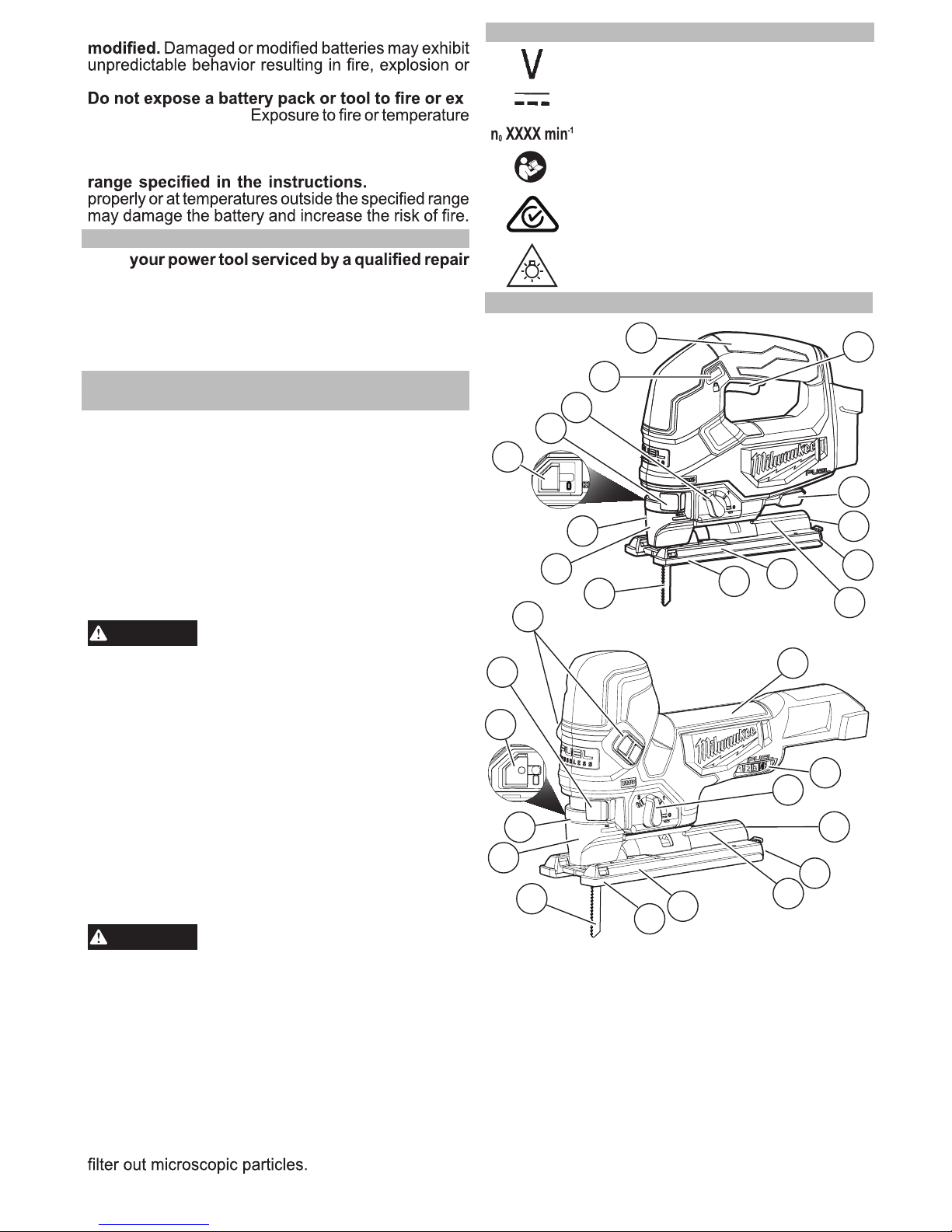
SYMBOLOGY
Volts
Direct Current
No Load Strokes per Minute (SPM)
FUNCTIONAL DESCRIPTION
1. Blade
2. Transparent blade
cover
3. LED
4. Quik-Lok tension lever
5. ON/OFF slide switches
6. Orbital action selector
lever
7. Lock button
8. Handle
9. Trigger
10. Shoe adjustment
lever
11. Variable speed dial
12. Dust chute
13. Wrench/wrench
storage
14. Tilt angle scale
15. Shoe
16. Shoe cover
17. Blower shuttle
Cat. No. M18 FBJS
11
1
2
8
4
12
13
14
15
5
6
16
3
17
6
Cat. No. M18 FJS
7
9
12
13
15
14
1
10
8
2
3
16
4
17
Maintain labels and nameplates. These carry
important information. If unreadable or missing,
contact a MILWAUKEE® service facility for a
replacement.
Regulatory Compliance mark (RCM).
This product meets applicable
regulatory requirements.
Read operator’s manual
Always use common sense and be cautious
when using tools. It is not possible to anticipate
every situation that could result in a dangerous
outcome. Do not use this tool if you do not
understand these operating instructions or you feel
the work is beyond your capability; contact
MILWAUKEE
®
Tool or a trained professional for
additional information or training.
WARNING! Do not stare into the LED.
Page 4
4
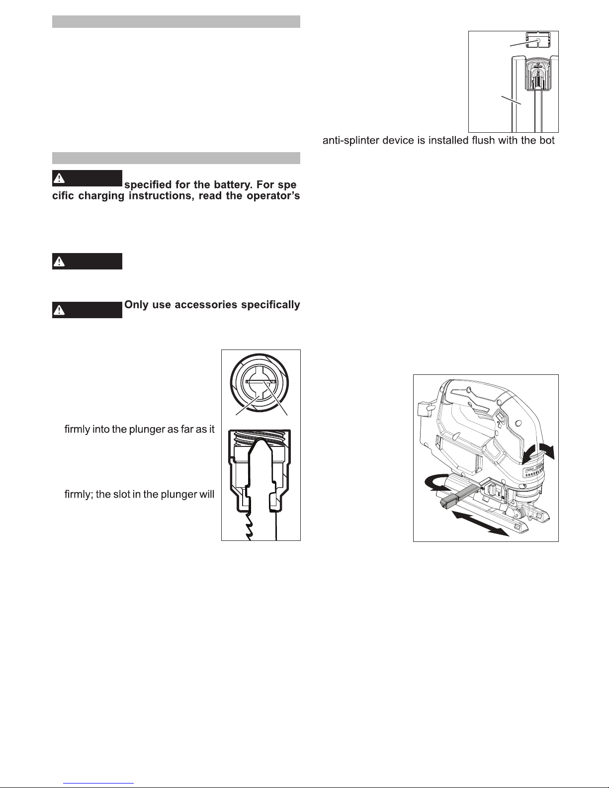
Installing the Anti-Splinter Device
The anti-splinter device helps
Shoe
Anti-splinter
device
stabilise the workpiece and reduce workpiece splinter.
NOTE: Do not use the transparent blade cover and anti-splinter
device when making bevel/
angle cuts.
1. Remove the battery pack.
2. Slide the anti-splinter device
onto the shoe. Make sure the
-
tom of the shoe.
Installing the Shoe Cover
The shoe cover is used to prevent marring and
scratching of the workpiece surface. To attach the
shoe cover:
1. Remove the battery pack.
2. Hook the front of the cover over the steel shoe.
3. Snap the rear of the shoe cover over the back of
the shoe. Be sure both sides are snapped in place.
4. When the shoe cover is not needed, remove it by
pulling the tabs on rear of the shoe cover down.
Unhook the front of the shoe cover and remove.
Adjusting the Shoe
The shoe may be tilted up to 45° in either direction.
NOTE: Do not use the transparent blade cover and
anti-splinter device when making bevel/angle cuts.
To set a tilt angle for bevel/angle cuts:
(Cat. No. M18 FJS)
1. Remove the battery pack.
2. Loosen the shoe
adjustment lever.
3. Pull the base forward slightly until
the detents are not
engaged.
4. Tilt the shoe to
the required preset angle (0°, 15°,
30°, or 45°) and
push the shoe into
the detent.
5. To set an angle
other than the presets, set the desired angle without
engaging a detent.
6. Tighten the shoe adjustment lever.
7. Make a test cut to verify the angle.
NOTE: If the shoe begins to slip when the lever is
tightened, use the 4 mm hex wrench stored in the
shoe to tighten the shoe adjustment hex sockets.
Remove the shoe cover, turn the tool over, and
tighten the hex sockets securely.
SPECIFICATIONS
Volts.............................................................18V DC
Battery Type
.................................................M18™
Charger Type................................................M18™
Recommended Ambient
Operating Temperature
....................-17°C to 51°C
Cat. No. .................................................M18 FJS-0
No Load Strokes per Minute ...................... 0 - 3500
Length of Stroke .....................................25 mm (1")
Cat. No.
...............................................M18 FBJS-0
No Load Strokes per Minute
.................. 800 - 3500
Length of Stroke .....................................25 mm (1")
ASSEMBLY
WARNING
Recharge only with the charger
-
manual supplied with your charger and battery.
Removing/Inserting the Battery
To remove the battery, push in the release buttons
and pull the battery pack away from the tool.
WARNING
Always remove battery pack before
changing or removing accessories.
To insert the battery, slide the pack into the body
of the tool. Make sure it latches securely into place.
WARNING
recommended for this tool. Others
may be hazardous.
Installing Saw Blades
Use only T-Shank jigsaw blades.
Slot Blade
1. Remove the battery pack.
2. Push and hold the Quik-Lok
tension lever to right to line up
the slots.
3. Fit the saw blade into the groove
in the support roller and push it
will go; the lug of the saw blade
must be in the plunger.
4. Release the Quik-Lok tension
lever to secure the saw blade.
5. Check that the saw blade is held
be at an angle to the blade.
6. To remove the blade, push the
lever to the right and the blade
will be ejected.
Installing the Transparent Blade Cover
Do not use the transparent blade cover and antisplinter device when making bevel/angle cuts.
1. Remove the battery pack.
2. To install, place the transparent blade cover in
front of the blade and slide it into place. The tabs
will snap into the slots on the housing.
3. To remove, press in the sides of the transparent
blade cover and pull away from the blade.
Page 5

5
(Cat. No. M18 FBJS)
NOTE: Do not attempt bevel cut with battery packs
larger than 5.0Ah. Battery packs larger than 5.0Ah
could result in the battery striking the workpiece
during the cut.
1. Remove the battery pack.
Bevel
Adjustment
Screw
2. Remove the shoe cover.
3. Turn the tool upside down to ex-
pose the bottom of the shoe.
4. Using the 4 mm hex wrench stored
in the shoe, loosen the bevel adjustment screw.
5. Pull the base forward slightly until
the detents are not engaged.
6. Tilt the shoe to the required preset
angle (0°, 15°, 30°, or 45°) and
push the shoe into the detent.
7. To set an angle other than the pre-
sets, set the desired angle without
engaging a detent.
8. Tighten the screw securely.
9. Make a test cut to verify the angle.
Selecting Speed
Use lower speeds for materials such as plastics and
laminates. Also, use lower speeds for hard metals.
Use higher speeds for materials such as wood and
soft metals (aluminum, copper, brass, etc.).
(Cat. No. M18 FJS)
To vary the speed, increase or decrease pressure
on the trigger. The further the trigger is pulled, the
greater the speed.
(Cat. No. M18 FBJS)
Rotate the speed selector dial to the desired speed
(1 through 6). Select "A" for Auto-Controlled Start to
start out at 1500 SPM and ramps up to 3500 SPM
once the workpiece is contacted.
WARNING
To reduce the risk of injury, wear a
dust mask or use an OSHA compliant dust extraction solution when working in
dusty situations.
Dust Collection Attachment
NOTE: For the M18 FBJS, the Dust Collection
Attachment cannot be used with battery packs larger
than 5.0Ah.
1. Remove the battery pack.
2. To install, line-up the small end of the dust collec-
tion attachment with the curved area at the back
of the shoe. Slide into place.
3. To remove, pull the attachment away from saw.
Blower shuttle
Set the blower shuttle to to blow air out the front
of the jigsaw to clear the cutting line of dust.
Set the blower shuttle to
to blow air out the dust
chute when using a dust extraction solution.
OPERATION
WARNING
Always remove battery pack before
changing or removing accesso-
-
mended for this tool. Others may be hazardous.
To reduce the risk of injury, wear safety goggles
or glasses with side shields. Keep hands away
from the blade and other moving parts.
To reduce the risk of injury, be sure the blade
always extends beyond the shoe and workpiece
throughout the stroke. Blades may shatter if they
impact the workpiece.
Starting and Stopping the Tool
(Cat. No. M18 FJS)
1. To start
the trigger.
2. To vary the speed, increase or decrease pressure
on the trigger. The further the trigger is pulled, the
greater the speed.
3. To stop the tool, release the trigger. Allow the tool
to come to a complete stop before removing the
blade from a partial cut or laying the tool down.
(Cat. No. M18 FBJS)
1. Set the speed control dial to the desired speed.
2. To start the tool, push the slide switch forward
until tool starts and release.
2. To vary the speed, turn the variable speed dial.
3. To stop the tool, press the slide switch and re-
lease. Allow the tool to come to a complete stop
before removing the blade from a partial cut or
laying the tool down.
NOTE: If the switch is held on for more than 3 sec-
Locking the Trigger
(Cat. No. M18 FJS)
To lock the trigger, push the trigger lock from the
lock side of the tool. The trigger will not work while
the switch is in the locked position. Always lock the
trigger and remove the battery pack before performing maintenance and changing accessories. Lock
the trigger when storing the tool and when the tool
is not in use.
To unlock the trigger, push the trigger lock from the
unlock side of the tool.
Adjusting the Orbital Action
The amount of orbital action may
be adjusted with the orbital action selector lever. In general, a
large orbital action (3) should be
used with soft materials and a no
orbital action (0) should be used
with hard materials. When a
smooth cut is required, no orbit
(0) should be used.
Material Orbital Action
Wood 0-3
Metal 0-1
Aluminum 0-1
Plastic 0-2
Smooth Cut 0
Page 6
6
WARNING
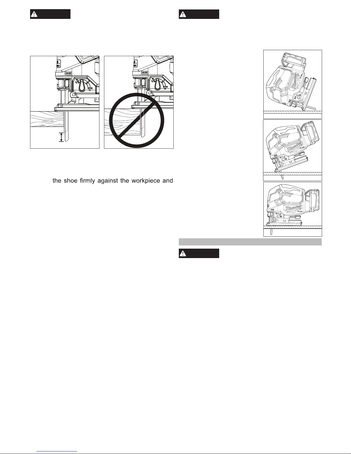
To reduce the risk of injury, do not
start the tool with the blade contacting the workpiece.
To reduce the risk of injury, be sure the blade
always extends beyond the shoe and workpiece
throughout the stroke. Blades may shatter if they
impact the workpiece.
Making the Cut
1. Set the orbital action according the material to be cut.
2. Position the tool with the front part of the shoe on
the workpiece and start the tool.
3. Hold
guide the tool along the desired cutting line. Do not
feed into the work too hard, light pressure on the
saw blade will achieve the optimum cutting speed.
Special Cutting Techniques
1. Straight cuts — To obtain a perfectly straight cut,
clamp a strip of wood as a guide along the workpiece or use the rip guide (accessory).
2. Bevel cuts — adjust the shoe to the correct angle
(see Adjusting the Shoe).
3. Cutting Sheet Metal — sheet metal may vibrate
when being cut. To minimise vibration, clamp the
workpiece to a wood base.
WARNING
To reduce the risk of explosion,
electric shock and property damage, always check the work area for hidden gas
pipes, electrical wires or water pipes when making blind or plunge cuts.
Plunge Cutting
Plunge cuts can be made into
soft materials without a predrilled hole. Harder materials
require a starter hole with a
diameter slightly over the width
of the blade. To make a plunge
cut:
1. Set the orbital action selec-
tor lever to 0.
2. Make sure nothing below
the intended cut area will
be damaged.
3. Without turning the tool on,
place the front edge of the
shoe solidly on workpiece.
4. Align the blade with the
intended cut line, but keep
it above the workpiece.
5. Using the front edge of the
shoe as a pivot, turn on the
tool and gradually lower the
blade into the workpiece.
6. When the shoe is flat
against the workpiece, normal cutting may take place.
MAINTENANCE
WARNING
To reduce the risk of injury, always
unplug the charger and remove the
battery pack from the charger or tool before
performing any maintenance. Never disassemble
the tool, battery pack or charger. Contact a
MILWAUKEE® service facility for ALL repairs.
Maintaining Tool
Keep your tool, battery pack and charger in good
repair by adopting a regular maintenance program.
Inspect your tool for issues such as undue noise,
misalignment or binding of moving parts, breakage
of parts, or any other condition that may affect the
tool operation. Return the tool, battery pack, and
charger to a MILWAUKEE® service facility for
repair. After six months to one year, depending on
use, return the tool, battery pack and charger to a
MILWAUKEE® service facility for inspection.
If the tool does not start or operate at full power with
a fully charged battery pack, clean the contacts on
the battery pack. If the tool still does not work
properly, return the tool, charger and battery pack,
to a MILWAUKEE® service facility for repairs.
Page 7

7
WARNING
To reduce the risk of personal injury and damage, never immerse
your tool, battery pack or charger in liquid or
Cleaning
Clean dust and debris from vents. Keep handles
clean, dry and free of oil or grease. Use only mild
soap and a damp cloth to clean, since certain cleaning agents and solvents are harmful to plastics and
other insulated parts. Some of these include gasoline,
turpentine, lacquer thinner, paint thinner, chlorinated
cleaning solvents, ammonia and household deter-
combustible solvents around tools.
Repairs
For repairs, return the tool, battery pack and charger
to the nearest service centre.
ACCESSORIES
WARNING
Use only recommended accessories. Others may be hazardous.
For a complete listing of accessories, go online to
www.milwaukeetools.com.au/
www.milwaukeetools.co.nz or contact a distributor.
Page 8

For a list of MILWAUKEE® dealers, guarantee or service agents please contact MILWAUKEE
®
Customer Service or visit our website.
(Australia Toll Free Telephone Number 1300 645 928)
(New Zealand Toll Free Telephone Number 0800 279 624)
or visit www.milwaukeetools.com.au / www.milwaukeetools.co.nz.
Milwaukee Electric Tool Corporation
13135 West Lisbon Road, Brookfield, Wisconsin U.S.A. 53005
Milwaukee Tool (Australia)
21 Kelletts Road, Rowville, VIC 3178
Melbourne, Australia
Milwaukee Tool (New Zealand)
2 Landing Drive, Mangere
Auckland, 2022, New Zealand
Designed by Milwaukee Electric Tool Corp.
Professionally Made in China for Milwaukee Tool (Australia) / Milwaukee Tool (New Zealand)
Printed in China
WARRANTY - AUSTRALIA and NEW ZEALAND
SERVICE - AUSTRALIA and NEW ZEALAND
MILWAUKEE®prides itself in producing a premium quality product that is Nothing But Heavy Duty®.
Your satisfaction with our products is very important to us! If you encounter any problems with the
operation of this tool, please contact your authorised MILWAUKEE® dealer.
Please refer to Australian and New Zealand warranty supplied with tool. This warranty applies only to
product sold in Australia and New Zealand.
961012729-01A
 Loading...