

Milwaukee DL100 Operation Manual
DL100 BLACK BOX
DATA LOGGING MONITOR
pH/Temperature
Set Up / Operation Manual
1
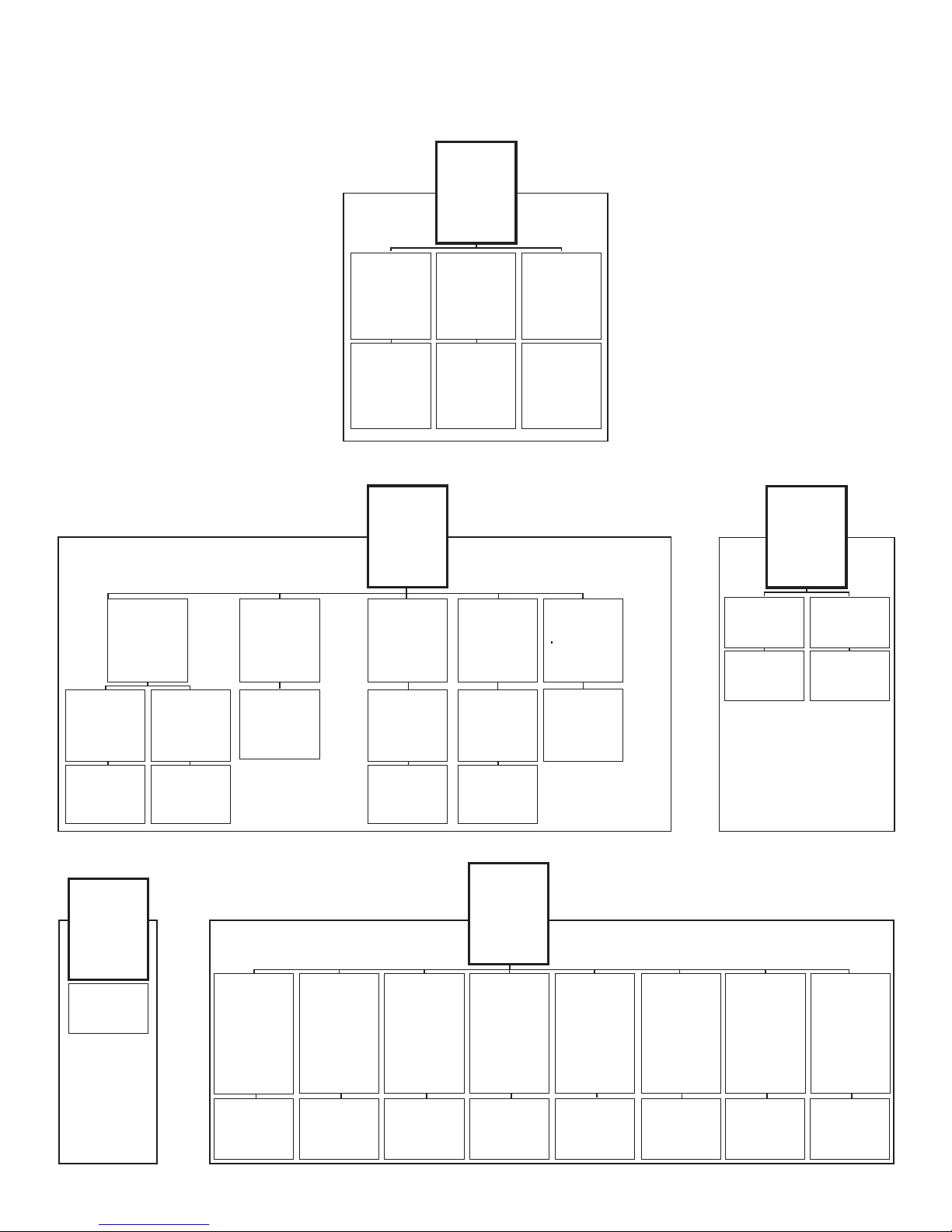
DL100 MENU MAP
**Menu**
> Basic Setup
pH
Data Log Setup
Last Logged
Wi-Fi Settings
Exit
**pH Menu**
> pH Calibration
pH Probe Diagnostic
pH Below Alert
pH Above Alert
Manual Temp Comp
Exit
**pH Calibration**
1 Point Calibration
> 2 Point Calibration
3 Point Calibration
Last Calib./GLP
Exit
7.01 & 4.01 Calibration
“Follow Instructions
Given Here”
Exit
**pH Calibration**
1 Point Calibration
2 Point Calibration
3 Point Calibration
> Last Calib./GLP
Exit
** Last Calib./GLP **
05/04/15 9:25:36
2 Point Calibration
7.01 & 4.01
Exit
**pH Menu**
pH Calibration
pH Probe Diagnostic
>
pH Below Alert
pH Above Alert
Manual Temp Comp
Exit
**Probe Diagnostic**
Follow instructions
given here.
Exit
**Basic Setup**
> Date & Time
Temperature
pH Resolution
Exit
Date and Time
> 05/09/15 Date
9:25 Time
Exit
**Menu**
Basic Setup
> pH
Data Log Setup
Last Logged
Wi-Fi Settings
Exit
**pH Menu**
pH Calibration
pH Probe Diagnostic
> pH Below Alert
pH Above Alert
Manual Temp Comp
Exit
*pH Below Alert*
> pH Caution **.**
pH Critical **.**
Exit
*pH Below Alert*
> pH Caution **.**
Exit
**Basic Setup**
Date & Time
> Temperature
pH Resolution
Exit
Temperature
> Fahrenheit
Celsius
Exit
**pH Menu**
pH Calibration
pH Probe Diagnostic
pH Below Alert
> pH Above Alert
Manual Temp Comp
Exit
*pH Above Alert*
> pH Caution **.**
pH Critical **.**
Exit
*pH Above Alert*
> pH Caution **.**
Exit
**Basic Setup**
Date & Time
Temperature
> pH Resolution
Exit
pH Resolution
Tenths .0
> Hundredths .00
Thousandths .000
Exit
**pH Menu**
pH Calibration
pH Probe Diagnostic
pH Below Alert
pH Above Alert
>Manual Temp Comp
Exit
*Manual Temperature*
Compensation
025.50º C
Basic Setup
pH
> Data Log Setup
Last Logged
Wi-Fi Settings
Exit
*Data Logger*
> Set Time Interval
Start Time
Exit
Set Time Interval
xx:xx:xx
**Menu**
Set Time Interval
> Start Time
Exit
*Data Logger*
Start Time
xx:xx:xx
**Menu**
Basic Setup
pH
Data Log Setup
> Last Logged
Wi-Fi Settings
Exit
**Last Logged**
01/05/16 08:06:07
pH: 7.00
Temp: 22.56º C
**Wi-Fi Settings**
Security Type
Network Name/SSID
Pre-shared Key
View Device IP
Upload Interval
Portal Sync
> Wi-Fi Enable
Portal Service
Exit
**Wi-Fi Enable**
> Enable
Disable
**Wi-Fi Settings**
Wi-Fi Enable
> Security Type
Network Name/SSID
Pre-shared Key
View Device IP
Upload Interval
Portal Sync
Portal Service
Exit
**Wi-Fi Security**
Open
WEP
> WPA
Exit
**Wi-Fi Settings**
Wi-Fi Enable
Security Type
> Network Name/SSID
Pre-shared Key
View Device IP
Upload Interval
Portal Sync
Portal Service
Exit
Network Name
XXXXXXXXXXXXX
**Menu**
Basic Setup
pH
Data Log Setup
Last Logged
> Wi-Fi Settings
Exit
**Wi-Fi Settings**
Wi-Fi Enable
Security Type
Network Name/SSID
> Pre-shared Key
View Device IP
Upload Interval
Portal Sync
Portal Service
Exit
Network Password
XXXXXXXXXXXXX
2
**Wi-Fi Settings**
Wi-Fi Enable
Security Type
Network Name/SSID
Pre-shared Key
> View Device IP
Upload Interval
Portal Sync
Portal Service
Exit
Device IP Address
IP: 196.162.3.***
MAC: 18fe351e79cd
Exit
**Wi-Fi Settings**
Wi-Fi Enable
Security Type
Network Name/SSID
Pre-shared Key
View Device IP
> Upload Interval
Portal Sync
Portal Service
Exit
Set Upload Interval
05 minutes
**Wi-Fi Settings**
Wi-Fi Enable
Security Type
Network Name/SSID
Pre-shared Key
View Device IP
Upload Interval
> Portal Sync
Portal Service
Exit
Portal Sync
**Wi-Fi Settings**
Wi-Fi Enable
Security Type
Network Name/SSID
Pre-shared Key
View Device IP
Upload Interval
Portal Sync
>
Portal Service
Exit
Do Not Enter
Any Data
Please make sure you have all the components
listed below. If not, call your dealer.
• DL100 Data Logging Monitor
• #MA911B/2 pH probe with 2m cable
• #RJ11 temperature probe with 3m cable
• 9VDC power supply
• 4GB SD card
• International power supply kit
DL100 Quick-Start Hardware Setup
1) Plug the pH probe into the BNC connector on the controller.
2) Insert the 4GB SD card (included), printed side down, making
certain that it snaps into place.
3) Connect RJ11 temperature probe.
4) Connect 9VDC power supply into unit rst, then plug into
120VAC wall outlet.
Note: To enable Wi-Fi, you will need to know your Wi-Fi network
Security Type, Name, and Password.
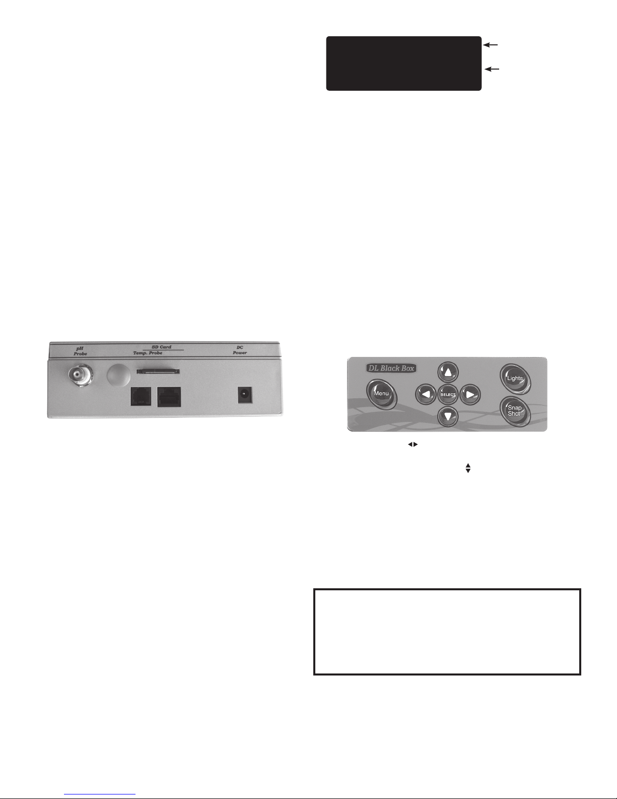
11/30/15 11:45 Wi-Fi
pH: 7.10
Temp: 22.56º C ATC
Wi-Fi will display
here, if enabled.
ATC or MTC will
display here.
Primary Display Screen
If temperature probe is plugged in, ATC (Automatic Temperature
Compensation) will appear in the lower right portion of screen.
If not, MTC (Manual Temperature Compensation) will display.
On the menu screens, only four lines will be visible at a time.
To see more options, scroll the list by using up/down arrows
on the keypad. When the cursor (>) appears beside the
appropriate function or setting, press SELECT.
THE KEYPAD Pressing the Menu button brings up a screen
featuring the full menu. At the bottom of all menu screens,
there will be an “Exit” option. The “Exit” option, when selected,
takes you back to the previous screen you were viewing. For
informational screens, there is no “Exit” option. Press SELECT to
return to previous screen.
Pressing the Menu button takes you all the way back to the
primary display screen, bypassing other screens you may have
used. Pressing the Menu button also allows you to toggle
between the primary display screen and the full menu screen.
Milwaukee Instruments, designer and manufacturer of the
DL100, recommends you read this manual from start-tonish, without skipping sections. Many of the instructions in
later sections are based on knowledge you will acquire in the
earlier sections of this manual.
Getting to know the DL100
Once you have connected all the cords, inserted the SD card, and
plugged the DL100 into a wall socket, please read this section,
taking a few moments to learn about the screen and keypad.
Note there is no ON/OFF switch; the unit is ON as soon as it is
plugged in. The only way to deactivate the unit is to unplug it.
Recorded data on the SD card will remain intact when the unit is
unplugged.
THE SCREEN When the unit is rst powered up, you will see a
WELCOME message. In a few seconds, the unit will automatically
switch to the primary display screen. This screen gives the date,
time, and real-time readings of pH and Temperature. If activated,
the word Wi-Fi will appear in the upper right corner. Unless you
are changing settings, this is the screen that should always be
displaying.
The left/right arrows ( ) allow you to move the blinking cursor
horizontally through a line of settings to the numbers you want
to reset, while the up/down arrows ( ) allow you to move
through the function listings and numbers, and toggle between
yes/no options. When new settings are entered, press SELECT,
there will be a short pause and the screen will read SAVED! In just
a moment, the unit will revert to the previous screen.
The Lights button allows you to turn o the screen and status
lights (lights to the left and right of screen, behind grills). The
unit is still functional when lights are o. Pressing Lights again
will reactivate all lights.
IMPORTANT: When in the Lights OFF mode, the status lights
(caution and critical) will not activate on the unit; however,
since the unit is still operational, it will continue to log data
and, if web portal is activated, send text or email alerts, or
both. The only way to turn o data logging and the alerts
system is to unplug the unit.
The Snap Shot button allows you to instantly log a real-time
reading on both the SD card and the portal. When you press
the Snap Shot button on the keypad, “Snap Shot” will appear
for a few seconds in the lower right corner of the screen,
indicating the real-time data has been logged.
1
 Loading...