


Milwaukee DescriptionDescriptionDescriptionDescription Service Parts List
SERVICE PARTS LIST
SPECIFY CATALOG NO. AND SERIAL NO. WHEN ORDERING PARTS
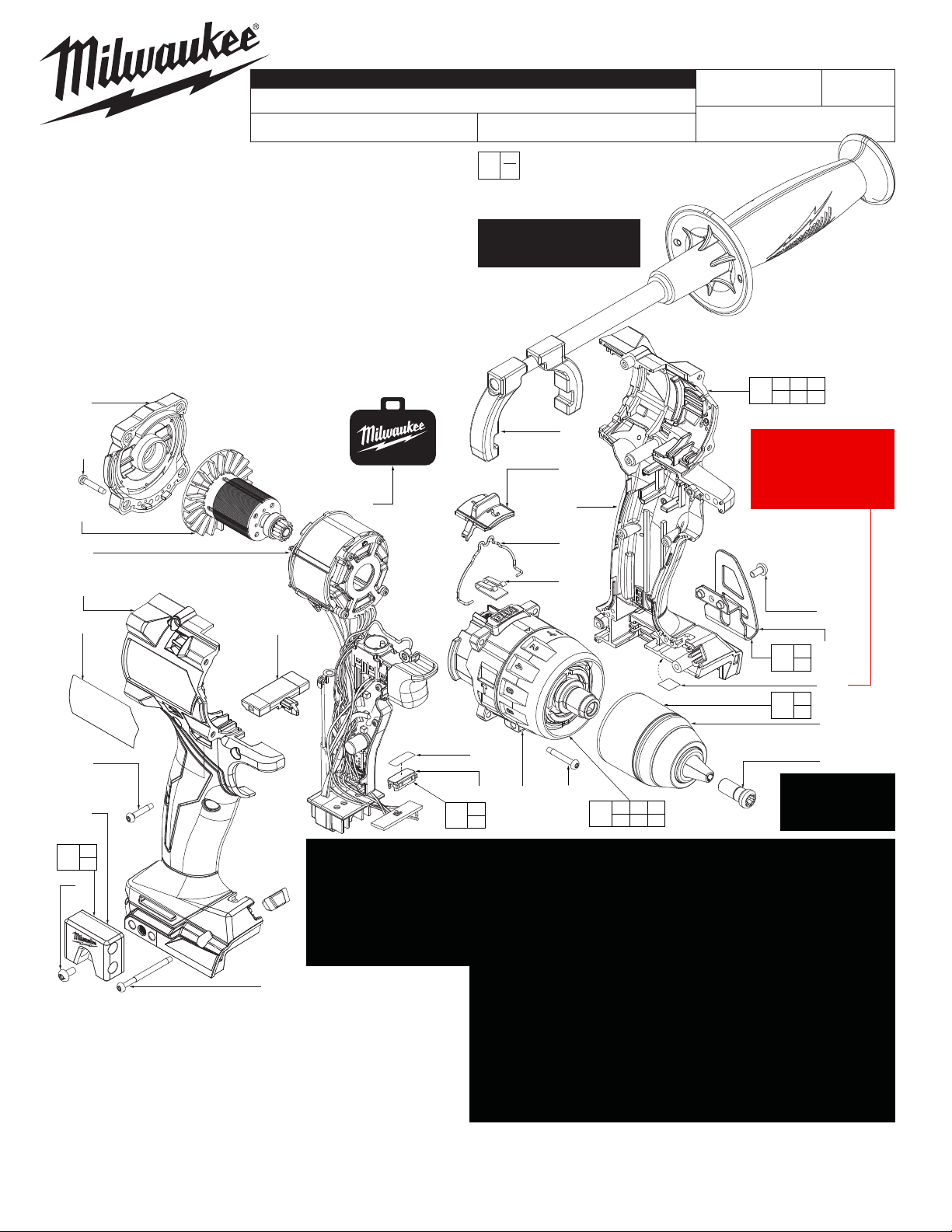
M18™ FUEL™ Brushless Hammer-Drill
FIG. PART NO. DESCRIPTION OF PART NO. REQ.
1 05-88-0019 M8.0 x 1 LH T-40 Chuck Screw (1)
2 --------------- 1/2” Keyless Chuck (1)
12 06-82-7337 M4 x 20mm Pan Hd. ST T-10 w/Washer Scr. (4)
19 42-92-7012 Back Cap (1)
20 06-82-6351 M3 x 16mm Pan Hd. ST T-10 Screw (9)
22 --------------- Lens (1)
23 --------------- Right Housing Halve - Cover (1)
24 42-42-7003 Forward/Reverse Shuttle (1)
25 06-82-2367 M3 x 38mm Pan Hd. ST T-10 Screw (2)
26 --------------- Bit Holder (1)
27 06-82-2500 #6-32 x 7mm Pan Hd. Machine Screw (2)
28 --------------- Belt Clip (1)
29 44-10-0160 Detent Spring (1)
30 45-24-2670 Speed Selector (1)
31 --------------- Left Housing Halve - Support (1)
59 44-10-4020 Shift Spring (1)
19
CATALOG NO. 2904-20
STARTING
SERIAL NO.
EXAMPLE:
00
0
Component Parts (Small #) Are Included
When Ordering The Assembly (Large #).
See page 3 for fastener
tightening procedure and
torque specications.
M64A
BULLETIN NO.
54-24-2990
REVISED BULLETIN
WIRING INSTRUCTION
SEE PAGE 2
20 23 25
64
31 62 76
DATE
Aug. 2022
20
(4x)
68
69
23
62
20
(5x)
26
See detail
on page 2
26
63
27
27
FIG. PART NO. DESCRIPTION OF PART NO. REQ.
62 12-20-9095 Service Nameplate (1)
63 49-16-3697 Bit Holder Kit (Accessory) (1)
64 31-44-7060 Housing Service Assembly (1)
65 42-70-0950 Belt Clip Service Kit (1)
66 --------------- Gearbox (1)
67 42-66-2720 1/2” Keyless Chuck (1)
68 16-07-2983 Rotor Service Assembly (1)
69 14-20-6560 Electronic Service Assembly (1)
70 42-62-0550 Side Handle Service Assembly (1)
71 42-55-9020 Blow Molded Carrying Case (1)
72 --------------- QR Code Label (1)
75 --------------- Auto-Stop Label (1)
76 31-44-7008 Lens/Label Assembly (1)
77 14-29-5015 Gearbox Service Assembly (1)
24
25(2x)
71
REMOVING THE CHUCK SCREW: Set the Speed Selector Slide to the #1 setting.
With the aid of a small pencil tip torch (or use an air reduction nozzle on a heat gun) apply heat
into the chuck opening, directly to the head of reversing screw just prior to removing the screw.
Place a T40 1/4” torx bit into the head of the reversing screw and place a 1/4” boxed end wrench
over the hex on the T40 bit. It is recommended to use a 12”-18” metal tube or pipe as leverage
over the boxed wrench. In a clockwise direction apply a slow, steady force on the ‘cheater bar’
to break the screw loose.
REMOVING THE KEYLESS CHUCK:
Tighten a 3/8” or 10mm Allen Key into the jaws of the chuck. Place
the tool into a vise with soft jaws (this will require that you remove
the belt clip from the tool). It is recommended to use a 12”-18” metal
tube or pipe as leverage over the allen key. In a counter-clockwise
direction apply a slow, steady force on the ‘cheater bar’ to break the
chuck loose.
INSTALLING NEW CHUCK AND SCREW:
Torque Chuck to 1095 kg/cm (950.418 in/lbs or 79.20 ft/lbs)
Torque Screw to 400 kg/cm (347 in/lbs or 28.93 ft/lbs)
76
22
75
75
22
66
70
30
31
59
29
12
(4x)
12 29 30
77
59 66
Note: QR codes are
not user-replaceable.
Return your tool to a
Milwaukee Authorized
Repair Center for QR
code replacement.
27
28
27
65
28
72
*
1
67
2
2
1
See instructions
below on how to
remove the chuck
screw and chuck
MILWAUKEE TOOL l www.milwaukeetool.com
13135 W. Lisbon Rd., Brookeld, WI 53005
Drwg. 3
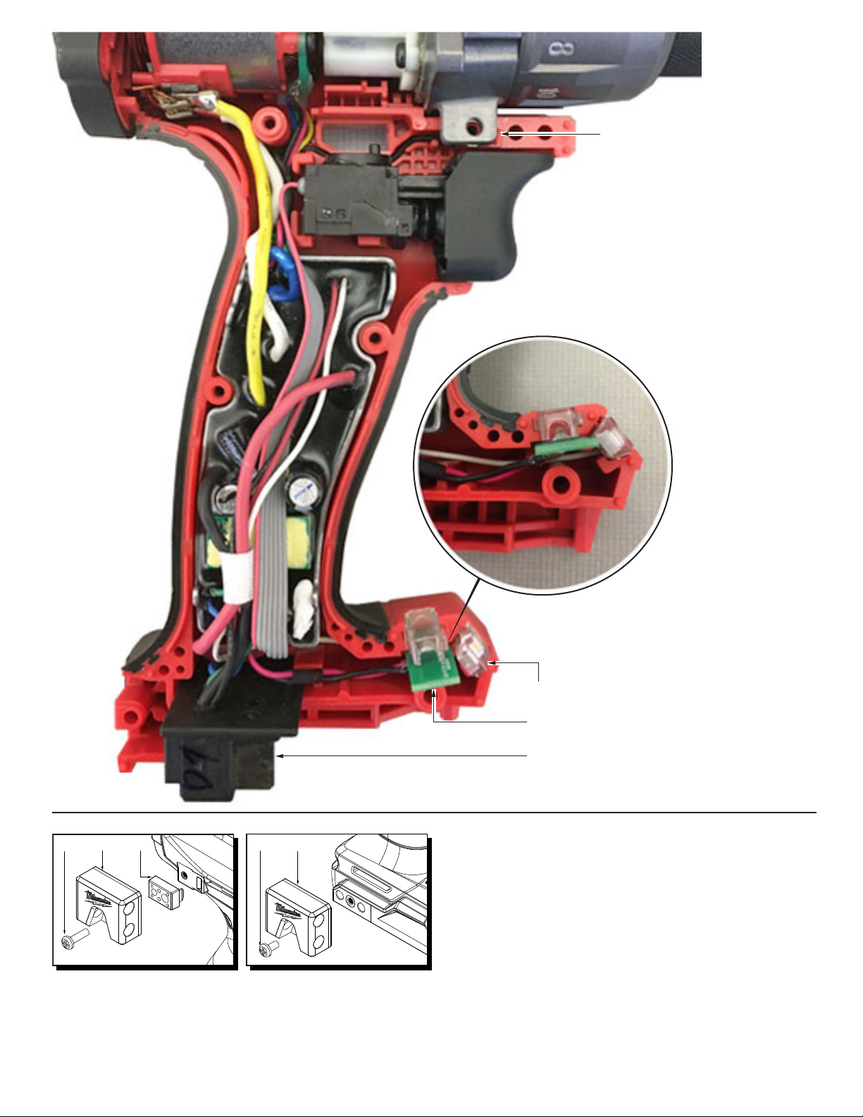
Bit Holder on M12™ Products Bit Holder on M18™ Products
a 06-82-3008 6-32 x 12.7mm Pan Hd. Phillips Screw (For M12™ Tools)
Position ground ring terminal behind lug of
gearcase. Route ground wire through wire
trap channel as shown. The view is shown
with forward/reverse shuttle removed.
a b c d b
49-16-3697 BIT HOLDER (ACCESSORY)
FIG. PART NO. DESCRIPTION OF PART
b --------------- Bit Holder
c --------------- Adapter (For M12™ Tools)
d 06-82-2500 6-32 x 7mm Pan Hd. Phillips Screw (For M18™ Tools)
FOR M18™ TOOLS, DISCARD KIT PARTS ‘A’ AND ‘C’.
1. Install LED light as shown.
2. Insert light board into housing cavity.
3. Place battery connector block into
corresponding housing cavity.
LED Light
Light Board
Battery Connector Block
FIG. SERVICE NOTES
62 A clean, dry surface is essential for proper performance
for any adhesive system. The area intended for
application of any adhesive label or nameplate must be
prepared by cleaning with isopropyl alcohol. The
solvent is to be applied with a clean, lint free applicator
and the surface allowed to dry before applying the
label or nameplate.