


Milwaukee 9562, 9565, 9566, 9560, 9568 User Manual
...
OPERATOR’S
MANUAL
ELECTRIC CHAIN HOIST
Catalog No. |
|
Rated Load |
9560 |
|
1/2 Ton |
9561 |
|
|
9562 |
|
|
9565 |
|
1 Ton |
9566 |
|
|
9567 |
|
|
9568 |
|
|
9570 |
|
2 Ton |
9571 |
|
|
9572 |
|
|
9573 |
|
|
|
|
|
|
|
|
|
|
|
The equipment described and illustrated in these instructions is intended for industrial use only and should not be used to lift, support or otherwise transport people.
Follow all instructions and warnings for inspecting, maintaining and operating this hoist.
The use of any hoist presents some risk of personal injury or property damage. That risk is greatly increased if proper instructions and warnings are not followed. Before using this hoist, each operator should become thoroughly familiar with all warnings, instructions, and recommendations in this manual. Retain this manual for future reference and use.
Forward this manual to the hoist operator.
Failure to operate the equipment as directed in the manual may cause injury.
Before using the hoist, fill in the information below. Model and serial numbers are stamped into the aluminum hoist housing.
Model Number
Serial Number
Purchase Date
WARRANTY
|
|
|
|
|
|
|
|
|
Every MILWAUKEE hoist is thoroughly |
This warranty does not apply where: |
|
||||
|
inspected and tested before leaving the |
(1) repairs or attempted repairs have been |
|
||||
|
manufacturing facilities. Should any |
made by persons other than MILWAUKEE |
|
||||
|
trouble develop, return the complete hoist |
personnel or Authorized Service Station |
|
||||
|
prepaid to the Factory, Branch or nearest |
Personnel; |
|
||||
|
Authorized MILWAUKEE Service Station. |
(2) repairs are required because of normal |
|
||||
|
If inspection shows the trouble is caused |
wear; |
|
||||
|
by defective workmanship or material, all |
(3) the hoist has been abused or involved |
|
||||
|
repairs will be made without charge and |
in an accident; |
|
||||
|
the hoist will be returned, transportation |
(4) misuse is evident such as caused by |
|
||||
|
prepaid. |
overloading the hoist beyond its rated |
|
||||
|
|
|
capacity; |
|
|||
|
|
|
(5) the hoist has been used after partial |
|
|||
|
|
|
failure; |
|
|||
|
|
|
(6) the hoist has been used with an |
|
|||
|
|
|
improper accessory. No other warranty, |
|
|||
|
|
|
written or verbal, is authorized. |
|
|||
|
|
|
|
|
|
|
|
|
|
|
|
|
|
|
|
|
|
|
|
|
|
|
|
|
|
|
|
|
|
|
|
|
|
|
|
|
|
|
|
Alterations or modifications of equipment and use of non-factory repair parts can lead to dangerous operation and injury.
TO AVOID INJURY:
•Do not alter or modify equipment
•Do not use equipment to lift, support or otherwise transport people
•Do not suspend unattended loads over people
Milwaukee Electric Tool Corporation
A company within the Atlas Copco Group 13135 West Lisbon Road • Brookfield, WI, U.S.A. 53005
58-12-9560d1 |
06/02 |
Printed in USA |
Milwaukee Electric Tool Corporation
13135 West Lisbon Road
Brookfield, Wisconsin 53005
TEL: (800) 729-3878
SAFETY PRECAUTIONS
Each MILWAUKEE Electric Chain Hoist is built in accordance with the specifications contained herein and at the time of manufacture complies with our interpretation of applicable sections of *American Society of Mechanical Engineers Code (ASME) B30.16 “Overhead Hoists,” the National Electrical Code (ANSI/NFPA 70) and the Occupational Safety and Health Act (OSHA). Since OSHA states the National Electrical Code applies to all electric hoists, installers are required to provide current overload protection and grounding on the branch circuit section in keeping with the code. Check each installation for compliance with the application, operation and maintenance sections of these articles.
*Copies of this standard can be obtained from ASME Order Department, 22 Law Drive, Box 2300, Fairfield, NJ 07007-2300, U.S.A.
Improper operation of a hoist can create a hazardous situation which, if not avoided, in death or serious injury. To avoid such a
hazardous situation, THE OPERATOR SHALL:
17.NOT operate beyond the limits of the load chain travel.
18.NOT leave load supported by the hoist unattended unless specific precautions have been taken.
19.NOT allow the load chain or hook to be used as an electrical or welding ground.
20.NOT allow the load chain or hook to be touched by a live welding electrode.
21.NOT remove or obscure the warnings on the hoist.
22.NOT operate a hoist on which the safety placards or decals are missing or illegible.
23.NOT operate a hoist unless it has been securely attached to a suitable support.
24.NOT operate a hoist unless load slings or other approved single attachments are properly sized and seated in the hook saddle.
25.Take up slack carefully - make sure load is balanced and load holding action is secure before continuing.
26.Shut down a hoist that malfunctions or performs unusually and report such malfunction.
27.Make sure hoist limit switches function properly.
28.Warn personnel of an approaching load.
Improper operation of a hoist can create a potentially hazardous situation which, if not avoided, could result in minor or moderate injury. To avoid such a potentially hazardous situation, THE OPERATOR SHALL:
1.Maintain firm footing or be otherwise secured when operating the hoist.
2.Check brake function by tensioning the hoist prior to each lift operation.
3.Use hook latches. Latches are to retain slings, chains, etc. under slack conditions only.
4.Make sure the hook latches are closed and not supporting any parts of the load.
5.Make sure the load is free to move and will clear all obstructions.
6.Avoid swinging the load or hook.
7.Make sure hook travel is in the same direction as shown on the controls.
8.Inspect the hoist regularly, replace damaged or worn parts, and keep appropriate records of maintenance.
9.Use MILWAUKEE recommended parts when repairing the unit.
10.Lubricate load chain per hoist manufacturer’s recommendations.
11.NOT use the hoist’s overload limiting clutch to measure load.
12.NOT use limit switches as routine operating stops. They are emergency devices only.
13.NOT allow your attention to be diverted from operating the hoist.
14.NOT allow the hoist to be subjected to sharp contact with other hoists, structures, or objects through misuse.
15.NOT adjust or repair the hoist unless qualified to perform such adjustments or repairs.
2

|
Milwaukee Electric Tool Corporation |
|
13135 West Lisbon Road |
|
Brookfield, Wisconsin 53005 |
|
TEL: (800) 729-3878 |
|
TABLE OF CONTENTS |
Safety Precautions ...................................................................................................................................................................... |
2 |
Hoist Specifications..................................................................................................................................................................... |
3 |
Application Information ............................................................................................................................................................... |
4 |
Safety Information ....................................................................................................................................................................... |
4 |
Installation ................................................................................................................................................................................... |
4 |
Operation .................................................................................................................................................................................... |
5 |
Maintenance ............................................................................................................................................................................... |
6 |
Wiring Diagrams ....................................................................................................................................................................... |
12 |
Trouble Shooting ....................................................................................................................................................................... |
13 |
Inspection and Maintenance Check List ................................................................................................................................... |
14 |
Recommended Lubrication Schedule....................................................................................................................................... |
15 |
Replacement Parts List............................................................................................................................................................. |
16 |
Parts Depot & Warranty Repair Centers................................................................................................................................... |
28 |
Warranty ..................................................................................................................................................................... |
Back Cover |
HOIST SPECIFICATIONS
MILWAUKEE Electric Chain Hoists are rugged, portable hoists that provide quick, precise lifting. The hoists are constructed of tough, but lightweight, die cast aluminum alloy housings. An oil bath transmission, equipped with heat-treated, alloy steel gears and an overload limiting clutch, provides smooth and reliable operation.
With a pushbutton station that fits comfortably in one hand, the operator can safely control the hoist while the other hand is free to guide the load. The electrical controls, which are readily accessed under the electrical cover, utilize quick connections for easy voltage conversions and a 24V control circuit for added safety.
Table 1 - Hoist Specifications
Other features that ensure the safe operation of MILWAUKEE Electric Chain Hoists include a magnetic disc brake that delivers sure stopping and secure holding of the load. Adjustable upper and lower limit switches regulate the load travel. As a standard, hooks are supplied with safety latches. For additional safety, a chain stop is attached to the slack end of the load chain.
MILWAUKEE Electric Chain Hoists are designed and tested in accordance with the American Society of Mechanical Engineers Code B30.16, “Safety Standard for Overhead Hoists.” Hoists are built in compliance with CSA, file number LR 44484. Made in U.S.A.
|
|
Lifting |
|
Control Cord |
|
|
Full Load |
|
|
Model |
Capacity |
Speed |
Lift |
Length |
Reeving |
HP |
Voltage |
Motor Amps* |
Phase |
|
(tons) |
(fpm) |
(ft) |
(ft) |
|
|
(AC) |
|
|
|
|
|
|
|
|
|
|
|
|
|
|
|
|
|
|
|
|
|
|
9560 |
1/2 |
16 |
10 |
6 |
Single-chained |
1/2 |
115/230V |
7.6/3.8 |
Single |
|
|
|
|
|
|
|
|
|
|
|
|
|
|
|
|
|
|
|
|
9561 |
1/2 |
16 |
15 |
11 |
Single-chained |
1/2 |
115/230V |
7.6/3.8 |
Single |
|
|
|
|
|
|
|
|
|
|
|
|
|
|
|
|
|
|
|
|
9562 |
1/2 |
16 |
20 |
16 |
Single-chained |
1/2 |
115/230V |
7.6/3.8 |
Single |
|
|
|
|
|
|
|
|
|
|
|
|
|
|
|
|
|
|
|
|
9565 |
1 |
16 |
10 |
6 |
Single-chained |
1 |
115/230V |
14/7** |
Single |
|
|
|
|
|
|
|
|
|
|
|
|
|
|
|
|
|
|
|
|
9567 |
1 |
16 |
15 |
11 |
Single-chained |
1 |
115/230V |
14/7** |
Single |
|
|
|
|
|
|
|
|
|
|
|
|
|
|
|
|
|
|
|
|
9568 |
1 |
16 |
20 |
16 |
Single-chained |
1 |
115/230V |
14/7** |
Single |
|
|
|
|
|
|
|
|
|
|
|
|
|
|
|
|
|
|
|
|
9566 |
1 |
16 |
10 |
6 |
Single-chained |
1 |
230/460V |
3.2/1.6 |
Three |
|
|
|
|
|
|
|
|
|
|
|
|
|
|
|
|
|
|
|
|
9570 |
2 |
8 |
10 |
6 |
Double-chained |
1 |
115/230V |
14/7** |
Single |
|
|
|
|
|
|
|
|
|
|
|
|
|
|
|
|
|
|
|
|
9572 |
2 |
8 |
15 |
11 |
Double-chained |
1 |
115/230V |
14/7** |
Single |
|
|
|
|
|
|
|
|
|
|
|
|
|
|
|
|
|
|
|
|
9573 |
2 |
8 |
20 |
16 |
Double-chained |
1 |
115/230V |
14/7** |
Single |
|
|
|
|
|
|
|
|
|
|
|
|
|
|
|
|
|
|
|
|
9571 |
2 |
8 |
10 |
6 |
Double-chained |
1 |
230/460V |
3.2/1.6 |
Three |
|
|
|
|
|
|
|
|
|
|
*At full load, it is not unusual for the hoist to draw in excess of the values listed when lifting. It is critical to ensure that the voltage at the hoist contactor does not drop below 10% of the nominal voltage of the hoist while it is lifting a load. Low voltage will result in higher amp draw, damage to the hoist, and potential fire hazards. MILWAUKEE is not responsible for any damages caused by an inadequate power source.
**The 1HP, 115/230V models must have a dedicated power circuit rated for at least 20A, 125V when they are wired for 115V. It is not unusual for these models to draw up to 20 amps at 115V when lifting at rated capacity. Refer to Table 3 before installation.
3
Milwaukee Electric Tool Corporation
13135 West Lisbon Road
Brookfield, Wisconsin 53005
TEL: (800) 729-3878
APPLICATION
This hoist is intended transporting freely capacity. MILWAUKEE other than those
Always disconnect the power source before working on or near a hoist or its connected load. If the power disconnect point is out of sight, lock it in the open position and tag to prevent unexpected application of power.
4.Protect the power cable and control cable from coming in contact with sharp objects.
5.Do not kink power cable and control cable and never allow the cable to come in contact with oil, grease, hot surfaces, or chemicals.
6.Make certain that the power source conforms to the requirements of your equipment.
7.Inspect the unit daily before operating hoist.
8.Cluttered areas and benches invite accidents.
9.The operator should not engage in any practice which will divert his attention while operating the hoist.
10.Before using the hoist, the operator should be certain that all personnel are clear.
11.Do not operate hoist with loads exceeding its rated capacity.
12.Supporting frames or beams used as a hoist hanger must have a greater load capacity than the hoist.
13.Do not attempt to operate hoist beyond normal maximum lift range.
14.Align hoist for a straight line pull. Avoid side pull or end pull.
15.Do not operate hoist with twisted or damaged chain.
16.Do not operate a damaged or malfunctioning hoist until necessary adjustments or repairs have been made.
17.Do not use hoist to lift people or to carry loads over people.
18.Do not leave a load suspended in the air unattended.
19.Always remove load before making repairs.
20.Do not remove or obscure capacity or warning decals.
Failure to comply with Safety Precautions outlined throughout this manual can result in serious injuries or death. Before using this hoist, each operator should become thoroughly familiar with all warnings, instructions and recommendations in this manual.
SAFETY INFORMATION
1.Follow all local electrical and safety codes, as well as the National Electrical Code (NEC) and the Occupational Safety and Health Act (OSHA) in the United States.
2.Hoist must be securely and adequately grounded. The hoist power cable is provided with an additional lead (green) for grounding purposes.
3.Be careful when touching the exterior of an operating motor; it may be hot enough to be painful or cause injury. With modern motors this condition is normal if operated at rated load and voltage (modern motors are built to operate at higher temperatures).
INSTALLATION
installing the hoist, check the following:
sure all supporting structures and attaching devices strong enough to hold your intended loads. If in doubt,
a qualified structural engineer.
b.Provide proper branch circuit protection for the hoist as recommended in the National Electrical Code.
c.The power supply should be within plus or minus 10% of the voltage specified on the motor nameplate. It is critical to use adequate sized power cables, especially with 1-phase hoists (See Table 3). Be sure dual voltage hoists are connected or wired to correspond with your power supply (See WIRING, page 9).
d.Installation area must provide operating conditions for the operator including sufficient room for the operator and other personnel to stand clear of the load at all times.
e.For installations where the slack chain hanging from the unit may be objectionable or hazardous, the use of a chain container is recommended. See INSTALLATION OF CHAIN CONTAINER ASSEMBLY.
4
Milwaukee Electric Tool Corporation
13135 West Lisbon Road
Brookfield, Wisconsin 53005
TEL: (800) 729-3878
2.Before operating the hoist, be sure to observe the following:
a.ALWAYS DISCONNECT HOIST FROM POWER SUPPLY before removing the electrical cover or when making any electrical connection in the hoist or pushbutton station.
b.The ground wire (green colored) of the power cable should always be connected to a suitable ground by means of a screw or clamp. An alligator clip does not make a safe ground connection.
c.When installing a three-phase hoist, make only temporary connections at the power source. Push the “UP” button and observe the direction of the load block. If it raises, the phasing is correct and permanent connections may be made at the power source. If the load block lowers when the “UP” button is pushed, release the button immediately since the limit switches will not operate to protect the hoist from over-travel. Reverse any two wires (except the green ground wire) at the power source to correct the load hook direction (phasing). Do not change connections in the hoist or pushbutton assembly.
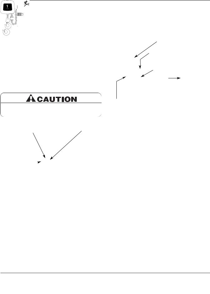
Dead-end Screw
Figure 1 — Installing Chain Container Assembly
4.Run the load hook down to its lowest position. Place the slack end of the chain in the chain container. Feed the remainder of the chain into the container by operating the hoist in the “UP” direction to the top limit. This will permit the chain to pile freely and eliminate the possibility of fouling which may occur if the chain is placed in the container by hand.
d.Make sure load chain is not twisted as it travels into the hoist.
e.Operate hoist in a hanging position only. Hoist should be permitted to align itself for a straight line pull. Do not attempt to pull around corners.
f.Read ASME-B30.16 Safety Code for Hoists.
3.If necessary, lubricate the chain, see LUBRICATION, page 9.
4.Check the function of the limit switches. Before placing hoist in operation, check limit switch adjustment. Operate pushbutton until near stop point and inch into stop limit both top and bottom. If either switch is not correct, adjust according to LIMIT SWITCH ADJUSTMENT, page 8.
INSTALLATION OF CHAIN CONTAINER ASSEMBLY (OPTIONAL ACCESSARY)
Refer to Figure 1 and Table 2.
1.Remove dead end screw and washers and let chain hang free.
2.Place chain container bracket flush against housing. Replace washers and screw. Tighten securely.
3.Attach chain container to bracket with two open links and then close the links.
Do not allow load to come in contact with chain container. If this situation exists reset the “UP” limit switch (See LIMIT SWITCH ADJUSTMENT, page 8) so that hook block stops below chain container.
Table 2 - Optional Chain Container
OPERATION
This hoist is designed for safe operation within the limits of its rated capacity. It is controlled with the “UP” and “DOWN” buttons of the pushbutton station. There are many safety features to protect the operator from injury due to failure of the hoist. Here are some points which should be observed to maintain safe operation.
1.Do not overload the hoist.
2.Do not make extreme side pulls with the hoist.
3.Operate the hoist only in a hanging position with adequate support.
4.Do not “sling” the load hook and chain around the load. Use an approved sling.
5.Be sure there are no twists in the load chain as it travels into the hoist housing. This condition should be constantly checked on double chain hoists because it is possible for the load block to be “capsized” or turned over one or more times.
6.Before raising a load, always check to see that it is held securely in the hook or sling chains, etc. Raise the load only until the load chain is taut and then double check the rigging before continuing to raise the load.
7.Do not stand beneath a load! Do not move a load in such a manner as to endanger personnel.
8.Do not lower into areas where visibility is obscured unless someone else is guiding the operation.
9.Use common sense at all times when operating a hoist.
10.Do not operate if direction of hook travel is not the same as indicated on button being pushed.
|
|
Standard |
|
Shipping |
|
|
|
|
Hoist |
Lifts |
Chain Container |
Weight |
|
Dimensions in Inches |
|
Capacity |
(ft) |
Required |
(lbs) |
Width |
Length |
Depth |
|
|
|
|
|
|
|
|
|
|
|
|
|
|
|
|
|
1/2 & 1 Ton |
10, 15, & 20 |
48-12-0111 |
3 |
3 |
6½ |
11½ |
|
|
|
|
|
|
|
|
|
|
|
|
|
|
|
|
|
2 |
Ton |
10 |
48-12-0111 |
3 |
3 |
6½ |
11½ |
|
|
|
|
|
|
|
|
|
|
|
|
|
|
|
|
2 |
Ton |
15 |
48-12-0112 |
4 |
3 |
6½ |
18½ |
|
|
|
|
|
|
|
|
|
|
|
|
|
|
|
|
2 |
Ton |
20 |
48-12-0113 |
5 |
6 |
6½ |
27 |
|
|
|
|
|
|
|
|
|
|
|
|
|
|
|
|
5
Milwaukee Electric Tool Corporation
13135 West Lisbon Road
Brookfield, Wisconsin 53005
TEL: (800) 729-3878
Do not use hoist to lift, support or otherwise transport people.
Do not allow screw driver blades to touch rotating friction disc “C”.
Do not allow the load to descend rapidly. This causes the motor to race and serious damage may result.
3. Use several quick releases instead of holding brake open
.
wear or signs. If the
have been is bent or
twisted more than 10° from the plane of an unbent hook must also be replaced.
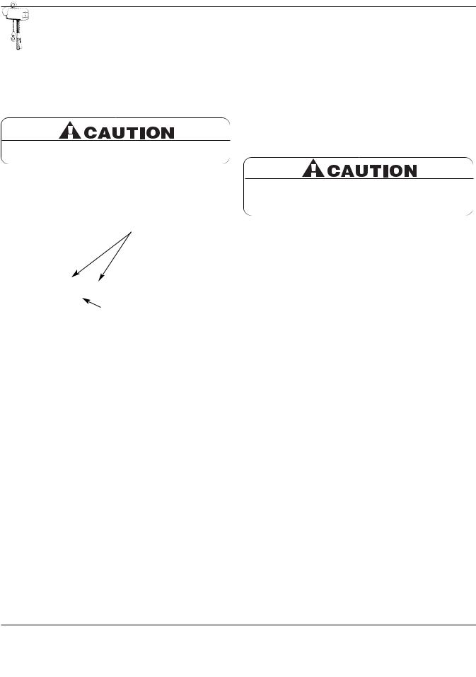
2. The hook latches should be inspected to ensure that they close the hook throat opening in a secure manner when a load is applied. Inspect the hook shank and nut for any stripping of the threads or other damage. The hook nut should be fully restrained by the retaining pin.
3. In addition to above, load hooks should be inspected for cracks by the magnetic particle, dye penetrant or other suitable crack testing inspection method. This should be done at least once a year.
Figure 2 — Hook
Inspection
|
|
“X” Dimension* |
Hoist |
Top |
Bottom |
Capacity |
Hook |
Hook |
1 Ton & Under |
111/32" |
17/32" |
2 Ton |
111/32" |
111/32" |
(*) Maximum permissible throat opening of hook.
6
Milwaukee Electric Tool Corporation
13135 West Lisbon Road
Brookfield, Wisconsin 53005
TEL: (800) 729-3878
CHAIN
Chain is to be kept clean and lubricated (See LUBRICATION, page 9). Visually check chain every time hoist is used. Hoist must not be operated when chain is twisted or kinked. An important phase of hoist maintenance is chain inspection. Check individual links and check for chain elongation.
1.Check the chain for overall wear or stretch by selecting an unworn, unstretched length of chain (at the slack end for example). Let the chain hang vertically with a light load (about 20 pounds) on the chain to pull it taut. Use a large caliper to measure the outside length of a convenient number of links (about 12"). Measure the same number of links in a used section of chain and calculate the percentage increase in length of the worn chain.
2.If the length of the worn chain is more than 1½% longer than the unused chain (0.015" per inch of chain measured), then
6.Using the “C” link, attach the new chain to the load end of the old chain. Be sure that the welds of the upstanding links of the new chain will face outward from the load sheave.
The end links must be oriented for attachment to the deadend screw and the chain support (double-chained only) without any twist in the chain.
Note Position
of Hook
Dead-End
Screw
TON |
Slack End |
TON |
Load End
-chained
Single-chained
Hoist
The chain used on this hoist has very carefully controlled dimensions and has been heat treated. Do not attempt to substitute other manufacturer’s chain.
Spring
Guide Plate
Silver Nut
(Down)
Gold Nut
(Up)
Figure 3 — Limit Switch Assembly
Chain Replacement with Chain in Hoist
Refer to Figures 3 & 4.
1.Run hook up to its top limit.
2.DISCONNECT HOIST FROM POWER SUPPLY and remove the electrical cover.
3.Using a screwdriver, pry the spring guide plate out of the slots in the limit switch nuts (See Figure 3). Turn the slotted nut nearest you, the gold nut, back to about the center of the threaded screw. Do not disconnect the wires from the limit switches.
4.Remove the load block assembly from the old chain. On double-chained hoists detach the chain from the chain support and pull it through the load block assembly (See Figure 4).
5.Make a “C” shaped chain link by grinding through the end link on the load end of the old chain.
Diagram
the hoist to the power ground wire is properly
grounded (See INSTALLATION, page 4).
8.Carefully jog the “UP” button and run the joined pieces of chain into the hoist until about 15" of the new chain comes out the other side.
9.DISCONNECT HOIST FROM POWER SUPPLY.
10.Remove the “C” link and the old chain. Remove the chain stop from the old chain by prying off its retaining ring with a flathead screwdriver. If attached, remove the old chain from the side of the hoist by removing the dead-end screw and washers (note placement of washers).
11.Attach the chain stop to the slack end of the new chain by capturing the 12th link with the two stop halves positioned with their tapered ends pointing towards the hoist. Slide the sleeve over the halves and attach the retaining ring. If you are not using a chain container, attach the slack end of the new chain to the side of the hoist using the dead-end screw and washers. With factory supplied hardware there should be six washers between the hoist and chain link and two washers between the chain link and screw head. DO NOT allow twists in the chain.
12.Adjust the lower limit switch (See ADJUSTING LOWER LIMIT, page 8).
13.Attach the bottom block on single-chained hoists using a new load block screw (See Figure 20). On double-chained hoists, feed the chain through the load block (welds of the upstanding links will be in towards the sheave) and fasten the end of the chain to the chain support using a new chain support pin (See Figure 20). Be sure there are no twists in the chain.
14.Adjust the upper limit switch (See ADJUSTING UPPER LIMIT, page 8).
7
Milwaukee Electric Tool Corporation
13135 West Lisbon Road
Brookfield, Wisconsin 53005
TEL: (800) 729-3878
Chain Replacement with No Chain in Hoist
Refer to Figures 4 and 5.
1.DISCONNECT HOIST FROM POWER SUPPLY and move hoist to a work table. Do not remove the electrical cover.
2.Lay the hoist on its side and remove the four screws that attach the sheave housing to the gear housing (See Figure 12, Ref. No. 2).
3.Carefully pull the sheave housing and motor assembly loose from the gear housing.
There are wires running through the hoist. Carefully ease the hoist sections apart. Do not jerk them apart.
1
Figure 5 — Chain Replacement with No Chain in Hoist
5.Remove the two chain guide plate screws (Ref. No. 2) and the nearest chain guide plate. Be careful not to lose the two spacers that are between the chain guide plates.
NOTE: Inspect chain guides and load sheave for wear, replace as needed.
6.Lay the new chain over the load sheave. Allow about 15" of chain below the hoist on the slack end (See Figure 4). Be sure the welds of the upstanding links are out away from the load sheave and that proper orientation is observed for attachment of the dead end. Also be sure the load hook assembly (if already attached to the chain) is toward the center of the hoist or to your right as you face the load sheave.
7.Replace the chain guide plate and the chain guide. Grease the splined shafts that project from both the housing and the motor.
8.Place the motor coupling on the splined shaft and carefully fit the two hoist sections together. Be sure the dead-end nut, the top hook and the support screw (double-chained hoists only) are all in place. On single-chained hoists, the hook shank goes in the center hole; on double-chained hoists, it goes in the off-center hole (See Figure 4). Be careful not to pinch any of the wiring. Turn the hoist on its side and replace the four screws and tighten securely.
9.Follow steps 11 through 14 in the previous section, CHAIN REPLACEMENT WITH CHAIN IN HOIST, to complete the chain replacement procedure.
If the wires running to the limit switches are ever disconnected for any purpose, be sure to replace wires in accordance with the correct wiring diagram (See WIRING DIAGRAMS, page 12).
Adjusting Upper Limit (Gold Nut)
Refer to Figure 3.
1.Suspend the hoist. For single-chained models raise the load block until there is a minimum clearance of 2" from the hoist housing and the top of the block. Double-chained models require a minimum clearance of 1" from the chain support to the top of the load block.
2.DISCONNECT HOIST FROM POWER SUPPLY and remove the electrical cover.
3.With a screwdriver, pry the spring guide plate out of the slots in the limit switch nuts.
4.Turn the slotted gold nut toward its limit switch until the switch “clicks” then turn two slots farther. Release the spring guide plate and be sure it slips back into the slots in both limit switch nuts. Do not disturb the silver slotted nut if it has been set previously.
Adjusting Lower Limit (Silver Nut)
Refer to Figure 3.
1.Suspend the hoist. Carefully lower the load block to a point where the slack-end loop of the chain hangs down 6" or more from the hoist housing (or the limit desired in any particular application allowing the minimum 6"). There should be a minimum clearance of 1½" between the chain stop and the bottom of the hoist.
2.DISCONNECT HOIST FROM POWER SUPPLY and remove the electrical cover.
3.With a screwdriver, pry the spring guide plate out of the slots in the limit switch nuts.
4.Turn the slotted silver nut toward its limit switch until the switch “clicks,” then turn two slots farther. Release the spring guide plate and be sure it slips back in the slots in both limit switch nuts. Do not disturb the gold slotted nut if it has been set previously.
Check Both Upper and Lower Limits
1.Connect the hoist to the power supply. Be sure the green ground wire is properly grounded .
2.Check load hook direction (See INSTALLATION 2-c, page 5).
8
Milwaukee Electric Tool Corporation
13135 West Lisbon Road
Brookfield, Wisconsin 53005
TEL: (800) 729-3878
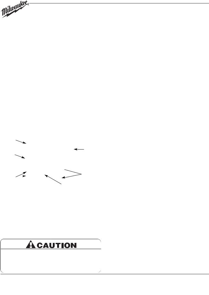
HOIST CONTROLS
B  F
F
G
E
Gap
A
X

 X
X
 C
C
D
H
Figure 6 — Brake Assembly
Be sure the bottom of the armature does not bear against the splined adapter “H”. As adjustments are made, the built-in clearance will be reduced. When this clearance is gone REPLACE BRAKE DISCS. Minimum allowable disc thickness is .162". See Figure 15 for further illustration.
Both the pushbutton and the reversing contactor are mechanically interlocked to prevent shorting the circuit and causing serious damage. As part of maintenance, always check for proper closure of contact points as well as for burned contacts. If replacement is necessary, see Figures 16 & 18 for replacement parts.
WIRING
Refer to Figures 9A and 9B
MILWAUKEE Electric Chain Hoists, which are available for 115/230V or 230/460V, are shipped wired for 115V and 460V respectively. Conversion of dual voltage hoists to either the higher or lower voltage can be done simply and quickly as follows:
1.DISCONNECT HOIST FROM POWER SUPPLY and remove the electrical cover.
2.Each dual-voltage hoist has a terminal block assembly for the interconnection of the electrical components of the hoist. To convert voltage, reconnect the leads to the terminal blocks according to the wiring diagram located inside the electrical cover and also in Figures 9A & 9B. DO NOT move any wires or make any changes to the electrical circuit except at the terminal block assembly. Tug on wires to ensure they are securely connected.
3.After converting voltage, recheck phasing and limit switch operation (See INSTALLATION 2-c & 4, page 5).
IMPORTANT: Always refer to the wiring diagram located on the inside of the electrical cover or Figures 9A and 9B when performing electrical repairs. Make sure all connections are secure and check for damaged insulation. It is also imperative that the power circuit has conductors of adequate size (See Table 3).
LUBRICATION
Refer to Figure 11.
Proper lubrication is necessary for a long and relatively troublefree hoist operation. Refer to the following and the RECOMMENDED LUBRICATION SCHEDULE for lubrication points, type of lubricant, and frequency of lubrication.
Load Chain
Clean the load chain with acid-free solvent and coat with SAE 90 gear oil. Wipe excess oil to prevent dripping. Never apply grease to the chain.
Gearing
The gear case of this hoist is filled at assembly with approximately 1½ pints of SAE 90 EP gear oil. Check oil level by removing the oil level check plug from the side of the hoist. With the hoist hanging level, gear oil should be even with the
of the least every
are additional
.
9
 Loading...